US11488564B2 - Display device having gap width measuring device between panels and control method therefor - Google Patents
Display device having gap width measuring device between panels and control method therefor Download PDFInfo
- Publication number
- US11488564B2 US11488564B2 US17/357,538 US202117357538A US11488564B2 US 11488564 B2 US11488564 B2 US 11488564B2 US 202117357538 A US202117357538 A US 202117357538A US 11488564 B2 US11488564 B2 US 11488564B2
- Authority
- US
- United States
- Prior art keywords
- gap
- panel
- row
- width
- luminous elements
- Prior art date
- Legal status (The legal status is an assumption and is not a legal conclusion. Google has not performed a legal analysis and makes no representation as to the accuracy of the status listed.)
- Active
Links
Images


Classifications
-
- G—PHYSICS
- G06—COMPUTING OR CALCULATING; COUNTING
- G06F—ELECTRIC DIGITAL DATA PROCESSING
- G06F3/00—Input arrangements for transferring data to be processed into a form capable of being handled by the computer; Output arrangements for transferring data from processing unit to output unit, e.g. interface arrangements
- G06F3/14—Digital output to display device ; Cooperation and interconnection of the display device with other functional units
- G06F3/1423—Digital output to display device ; Cooperation and interconnection of the display device with other functional units controlling a plurality of local displays, e.g. CRT and flat panel display
- G06F3/1446—Digital output to display device ; Cooperation and interconnection of the display device with other functional units controlling a plurality of local displays, e.g. CRT and flat panel display display composed of modules, e.g. video walls
-
- G—PHYSICS
- G09—EDUCATION; CRYPTOGRAPHY; DISPLAY; ADVERTISING; SEALS
- G09G—ARRANGEMENTS OR CIRCUITS FOR CONTROL OF INDICATING DEVICES USING STATIC MEANS TO PRESENT VARIABLE INFORMATION
- G09G3/00—Control arrangements or circuits, of interest only in connection with visual indicators other than cathode-ray tubes
- G09G3/20—Control arrangements or circuits, of interest only in connection with visual indicators other than cathode-ray tubes for presentation of an assembly of a number of characters, e.g. a page, by composing the assembly by combination of individual elements arranged in a matrix no fixed position being assigned to or needed to be assigned to the individual characters or partial characters
-
- G—PHYSICS
- G09—EDUCATION; CRYPTOGRAPHY; DISPLAY; ADVERTISING; SEALS
- G09G—ARRANGEMENTS OR CIRCUITS FOR CONTROL OF INDICATING DEVICES USING STATIC MEANS TO PRESENT VARIABLE INFORMATION
- G09G5/00—Control arrangements or circuits for visual indicators common to cathode-ray tube indicators and other visual indicators
- G09G5/10—Intensity circuits
-
- G—PHYSICS
- G01—MEASURING; TESTING
- G01B—MEASURING LENGTH, THICKNESS OR SIMILAR LINEAR DIMENSIONS; MEASURING ANGLES; MEASURING AREAS; MEASURING IRREGULARITIES OF SURFACES OR CONTOURS
- G01B21/00—Measuring arrangements or details thereof, where the measuring technique is not covered by the other groups of this subclass, unspecified or not relevant
- G01B21/16—Measuring arrangements or details thereof, where the measuring technique is not covered by the other groups of this subclass, unspecified or not relevant for measuring distance of clearance between spaced objects
-
- G—PHYSICS
- G09—EDUCATION; CRYPTOGRAPHY; DISPLAY; ADVERTISING; SEALS
- G09F—DISPLAYING; ADVERTISING; SIGNS; LABELS OR NAME-PLATES; SEALS
- G09F9/00—Indicating arrangements for variable information in which the information is built-up on a support by selection or combination of individual elements
- G09F9/30—Indicating arrangements for variable information in which the information is built-up on a support by selection or combination of individual elements in which the desired character or characters are formed by combining individual elements
- G09F9/301—Indicating arrangements for variable information in which the information is built-up on a support by selection or combination of individual elements in which the desired character or characters are formed by combining individual elements flexible foldable or roll-able electronic displays, e.g. thin LCD, OLED
-
- G—PHYSICS
- G09—EDUCATION; CRYPTOGRAPHY; DISPLAY; ADVERTISING; SEALS
- G09G—ARRANGEMENTS OR CIRCUITS FOR CONTROL OF INDICATING DEVICES USING STATIC MEANS TO PRESENT VARIABLE INFORMATION
- G09G3/00—Control arrangements or circuits, of interest only in connection with visual indicators other than cathode-ray tubes
- G09G3/03—Control arrangements or circuits, of interest only in connection with visual indicators other than cathode-ray tubes specially adapted for displays having non-planar surfaces, e.g. curved displays
- G09G3/035—Control arrangements or circuits, of interest only in connection with visual indicators other than cathode-ray tubes specially adapted for displays having non-planar surfaces, e.g. curved displays for flexible display surfaces
-
- G—PHYSICS
- G09—EDUCATION; CRYPTOGRAPHY; DISPLAY; ADVERTISING; SEALS
- G09G—ARRANGEMENTS OR CIRCUITS FOR CONTROL OF INDICATING DEVICES USING STATIC MEANS TO PRESENT VARIABLE INFORMATION
- G09G3/00—Control arrangements or circuits, of interest only in connection with visual indicators other than cathode-ray tubes
- G09G3/20—Control arrangements or circuits, of interest only in connection with visual indicators other than cathode-ray tubes for presentation of an assembly of a number of characters, e.g. a page, by composing the assembly by combination of individual elements arranged in a matrix no fixed position being assigned to or needed to be assigned to the individual characters or partial characters
- G09G3/22—Control arrangements or circuits, of interest only in connection with visual indicators other than cathode-ray tubes for presentation of an assembly of a number of characters, e.g. a page, by composing the assembly by combination of individual elements arranged in a matrix no fixed position being assigned to or needed to be assigned to the individual characters or partial characters using controlled light sources
- G09G3/30—Control arrangements or circuits, of interest only in connection with visual indicators other than cathode-ray tubes for presentation of an assembly of a number of characters, e.g. a page, by composing the assembly by combination of individual elements arranged in a matrix no fixed position being assigned to or needed to be assigned to the individual characters or partial characters using controlled light sources using electroluminescent panels
- G09G3/32—Control arrangements or circuits, of interest only in connection with visual indicators other than cathode-ray tubes for presentation of an assembly of a number of characters, e.g. a page, by composing the assembly by combination of individual elements arranged in a matrix no fixed position being assigned to or needed to be assigned to the individual characters or partial characters using controlled light sources using electroluminescent panels semiconductive, e.g. using light-emitting diodes [LED]
-
- G—PHYSICS
- G09—EDUCATION; CRYPTOGRAPHY; DISPLAY; ADVERTISING; SEALS
- G09G—ARRANGEMENTS OR CIRCUITS FOR CONTROL OF INDICATING DEVICES USING STATIC MEANS TO PRESENT VARIABLE INFORMATION
- G09G2300/00—Aspects of the constitution of display devices
- G09G2300/02—Composition of display devices
- G09G2300/026—Video wall, i.e. juxtaposition of a plurality of screens to create a display screen of bigger dimensions
-
- G—PHYSICS
- G09—EDUCATION; CRYPTOGRAPHY; DISPLAY; ADVERTISING; SEALS
- G09G—ARRANGEMENTS OR CIRCUITS FOR CONTROL OF INDICATING DEVICES USING STATIC MEANS TO PRESENT VARIABLE INFORMATION
- G09G2310/00—Command of the display device
- G09G2310/02—Addressing, scanning or driving the display screen or processing steps related thereto
- G09G2310/0232—Special driving of display border areas
-
- G—PHYSICS
- G09—EDUCATION; CRYPTOGRAPHY; DISPLAY; ADVERTISING; SEALS
- G09G—ARRANGEMENTS OR CIRCUITS FOR CONTROL OF INDICATING DEVICES USING STATIC MEANS TO PRESENT VARIABLE INFORMATION
- G09G2320/00—Control of display operating conditions
- G09G2320/02—Improving the quality of display appearance
- G09G2320/0233—Improving the luminance or brightness uniformity across the screen
-
- G—PHYSICS
- G09—EDUCATION; CRYPTOGRAPHY; DISPLAY; ADVERTISING; SEALS
- G09G—ARRANGEMENTS OR CIRCUITS FOR CONTROL OF INDICATING DEVICES USING STATIC MEANS TO PRESENT VARIABLE INFORMATION
- G09G2320/00—Control of display operating conditions
- G09G2320/06—Adjustment of display parameters
- G09G2320/0686—Adjustment of display parameters with two or more screen areas displaying information with different brightness or colours
-
- G—PHYSICS
- G09—EDUCATION; CRYPTOGRAPHY; DISPLAY; ADVERTISING; SEALS
- G09G—ARRANGEMENTS OR CIRCUITS FOR CONTROL OF INDICATING DEVICES USING STATIC MEANS TO PRESENT VARIABLE INFORMATION
- G09G2360/00—Aspects of the architecture of display systems
- G09G2360/16—Calculation or use of calculated indices related to luminance levels in display data
-
- G—PHYSICS
- G09—EDUCATION; CRYPTOGRAPHY; DISPLAY; ADVERTISING; SEALS
- G09G—ARRANGEMENTS OR CIRCUITS FOR CONTROL OF INDICATING DEVICES USING STATIC MEANS TO PRESENT VARIABLE INFORMATION
- G09G2380/00—Specific applications
- G09G2380/02—Flexible displays
Definitions
- the present disclosed subject matter relates to a display device comprising at least a first and a second panel, each of which comprises luminous elements arranged in rows and columns and which can be aligned with one another to form a gap running parallel to the columns, and at least one connecting element for holding the panels in their aligned position.
- the disclosed subject matter further relates to a panel, particularly for such a display device, and a method for controlling such a display device.
- Modular display devices of this type are used to form a common flat or curved image area from a plurality of aligned panels and to reproduce image or video signals by means of their luminous elements (“pixels”).
- pixels luminous elements
- LEDs Light-emitting diodes
- OLEDs organic materials
- gaps between the panels can significantly impair the image quality when the gap width and the variation thereof along the gap cause uneven luminous element spacings and therefore disturbing irregularities in image brightness that are perceptible to the human eye. For example, gaps which fall below or exceed a regular luminous element spacing appear lighter or darker to the viewer than the rest of the image area.
- a certain minimum gap width is often required not only to accommodate component tolerances and thermal expansion, but also to prevent the luminous elements from hitting one another at the gap in the event of vibrations or wind, which can lead to damage to the luminous elements close to the gap.
- the gap width can often not be reduced to the same extent, be it because of production-related component tolerances or necessary minimum housing wall thicknesses of the luminous elements, so that excessive gaps here are also due to the design.
- the goal of the disclosed subject matter is to create display devices, panels and control methods therefor which overcome the mentioned disadvantages of the known art and contribute to decreasing the visibility of construction-related or operational gaps between the panels.
- At least a first and a second panel each of which comprises luminous elements arranged in rows and columns and which can be aligned with one another to form a gap running parallel to the columns,
- a measuring device which is configured to determine, for a row of the first panel, a width of the gap at the level of said row, and
- a driver which receives a signal to be displayed and is connected to the measuring device and at least one luminous element of said row, which driver is configured to control said luminous element as a function of both the signal and the gap width determined for said row.
- the panels considered here can lie next to one another as well as one below the other, wherein, in the first case, the rows run horizontally and in the second case vertically, that is, in both cases normal to the gap.
- the display device uses a psycho-optical effect (“optical illusion”) to dynamically correct the visibility of the gaps between the panels:
- the driver scales the image or video signal to be reproduced by the luminous elements so that the physically existing gap between the two panels is less perceived by the viewer. For example, when the gap width exceeds the average luminous element spacing, that is, when the gap is too large, the driver can increase the brightness of luminous elements close to the gap in order to make the otherwise darker gap no longer perceptible to the human eye as dark.
- the driver multiplies, for example, the video signal for the luminous element(s) closest to the gap in a row by a factor greater than one, for example, to lengthen the pulse duration of pulse-width modulated luminous elements or to increase the voltage applied to voltage-controlled luminous elements, or the driver, when the gap is too small, decreases the brightness of the luminous element(s) close to the gap in order to make the gap, which otherwise appears brighter, less noticeable to the viewer.
- the driver can be configured to increase the brightness of at least one luminous element closer to the gap relative to the brightness of at least one luminous element further away from the gap, when the determined gap width is greater than an average distance between the luminous elements in said row, and to decrease said brightness when the determined gap width is smaller than the average distance between the luminous elements in said row.
- the increase in brightness of the luminous elements close to the gap which is required to compensate for perception of the overly large gap, can thus be achieved in three ways: by increasing the brightness of the luminous elements close to the gap, by reducing the brightness of the luminous elements distant from the gap, or both; and all this vice versa to compensate for perceptions of an overly small gap. Overdriving of the luminous elements can also be prevented by appropriate selection among these options, as is described in more detail later.
- the gap compensation according to the disclosed subject matter is suitable for all types of display devices composed of panels.
- the connecting elements between the panels can accordingly be rigid or articulated, detachable or non-detachable.
- the connecting element for holding and aligning two panels is, for example, a common carrier on which the panels are mounted, or one or more tabs, adhesive, riveted or welded seams, via which the panels are connected to one another.
- the present disclosed subject matter is particularly advantageous for display devices having movable and/or detachably couplable panels, for example, foldable or pluggable panels.
- the connecting element is therefore a joint, via which the panels can be pivoted between the aligned position and a folded position.
- the display device can be folded up like a fan-fold, that is, the panels can be folded onto one another in a zigzag shape by means of the joints, as described in the documents EP 2 443 621 B1, EP 2 568 464 B1 and AT 515846 B1.
- the connecting element is a coupling via which the panels are detachably connected.
- the coupling can, for example, be a plug-in or screw coupling directly between the panels, or a common carrier with which the panels can be detachably coupled.
- the panels can easily be detached from one another, temporarily stored and transported individually in a space-saving manner and then coupled together for reconstruction.
- the measuring device can be used once after each (re-)alignment of the panels to determine the current gap width(s), on the basis of which the driver controls the luminous elements to reduce the gap visibility.
- the measuring device is configured to continuously determine said gap width during operation of the display device.
- Continuous in this context means that the measuring device determines the gap width continuously or at—e.g., regular—time intervals, for example, every second, minute, hour, etc., for one or more rows.
- the driver controls the luminous elements on the basis of the currently determined gap width, so to speak “dynamically” according to the relative position and relative movement of the panels in order to achieve the described reduction in gap visibility.
- the measuring device can comprise only one sensor which determines a single, uniform gap width for all rows of the display device.
- the measuring device optionally comprises at least two sensors spaced apart from one another in the longitudinal extension direction of the gap, of which the first measures a first width of the gap at the level of the first sensor and the second measures a second width of the gap at the level of the second sensor, wherein the measuring device is configured to determine the gap width at the level of said row on the basis of the measured first and second widths.
- a gap that widens or narrows over the longitudinal extent of the gap for example, between panels that are misaligned at an angle, can be measured. From the measured values of the two sensors, the measuring device can then determine the respective gap width for each row lying between or outside the two sensors through appropriate interpolation or extrapolation.
- Each sensor can either be arranged entirely on the one panel or entirely on the other panel in order to measure the gap width at the level thereof, or it can consist of two sensor parts lying opposite one another on both sides of the gap and distributed on the panels, which sensor parts measure the gap width between one another.
- the one sensor when using two sensors, the one sensor could be arranged on the first panel and the other sensor on the second panel in order to reduce the number of sensors required per panel.
- the measuring device can also comprise three or more sensors in further embodiments and use the gap widths measured by said sensors for a corresponding curve interpolation or extrapolation to determine the gap width at the level of each row.
- each panel of the display device can be equipped with its own measuring device and its own driver and independently carry out said brightness control of its luminous elements to compensate for the perception of the gap.
- the brightness control can take place either on one side, wherein each panel is associated with its own gap that is perception-compensated only by means of its luminous elements, for example, the gap to the left of the panel, or on both sides, wherein one gap is associated with a plurality of panels, by means of the luminous elements of which the gap is perception-compensated.
- two adjacent panels can share a measuring device, that is, the measuring device of the first panel is configured to also determine a width of the gap at the level of said row for at least one row of the second panel, and said driver of the first panel, or a corresponding further driver of the second panel, is configured to control at least one luminous element of said row of the second panel as a function of the gap width determined therefor.
- the number of components can thereby be reduced.
- the brightness reserve (“headroom”) required to avoid overdriving the luminous elements close to the gap if the gaps are too large can be halved and, conversely, the drive range of all luminous elements that can be used to reproduce the video signal can thus be increased.
- the luminous elements of a panel can be controlled as a function of the width of only a single gap, particularly the luminous elements close to the gap and/or in a panel on the edge of the display device which comprises only one adjacent panel.
- the measuring device can optionally also be configured to determine a width of said further gap, and the driver can be configured to control said luminous element also as a function of the determined width of the further gap.
- Said further gap can either run parallel to the rows or parallel to the columns of the first panel, that is, the first, second and third panels can be arranged linearly next to one another or in an L-shape (“across the corner”). Controlling the luminous elements of the middle panel of such a group of three as a function of the two gap widths makes it possible to simultaneously both to reduce the visibility of both gaps and to maximize the brightness of the luminous elements for the reproduction of the image or video signal.
- the brightness reserve that is required to increase the brightness of luminous elements close to the gap to reduce their visibility can be determined on the basis of the largest of all determined gap widths in order to simultaneously reduce the gap visibility, achieve maximum brightness for video signal reproduction and prevent overdriving of luminous elements close to the gap.
- the display device can comprise further panels that can be aligned with the first panel, for example, a fourth, fifth, etc., whereby the visibility of all further gaps thus formed can be reduced by determining the respective gap widths and controlling the luminous elements on the basis of the determined gap widths.
- the disclosed subject matter provides a panel, particularly for the display device described above, which comprises luminous elements arranged in rows and columns and can be aligned with at least one second panel, to form a gap running parallel to the columns, which panel is characterized by a measuring device according to the disclosed subject matter which is configured, for a row of the panel, to determine a width of the gap at the level of said row, and a driver that receives a signal to be displayed and is connected to the measuring device and at least one luminous element of said row and is configured to control said luminous element as a function of both the signal and the gap width determined for said row.
- the panel of the disclosed subject matter enables strict modularization of the display device.
- a plurality of panels of the same type can be put together like building blocks.
- a wide variety of display devices can be built cost-effectively from the same standardized modules, namely panels and respectively associated connecting elements, measuring devices, sensors and drivers, which considerably simplifies production, storage, sales and assembly.
- the measuring device comprises at least a sensor which is integrated into a peripheral side of the panel facing the gap.
- the integration of the sensor into the peripheral side of the panel enables particularly small gap widths.
- the integration protects the sensor from damage during storage and transport of the panels and when folding, plugging together or assembling the display device.
- the disclosed subject matter also provides a method for controlling a display device having at least a first and a second panel, each of which comprises luminous elements arranged in rows and columns and which can be aligned with one another to form a gap running parallel to the columns, which method is characterized according to the disclosed subject matter by:
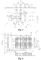
- FIG. 1 a display device according to the disclosed subject matter comprising five panels according to the disclosed subject matter in an aligned position in a front view;
- FIG. 2 the display device of FIG. 1 in a folded position in a top view
- FIG. 3 the principle of the brightness control of luminous elements close to the gap of two panels of the display device of FIG. 1 in a schematic representation
- FIG. 4 a block diagram of the display device of FIG. 1 ;
- FIGS. 5 to 7 further embodiments of the display device of the disclosed subject matter in the form of sections of block diagrams.
- the image area formed by the aligned panels P i can be both flat and curved, for example, comprising convex curved panels P i for electronic advertising columns or public viewing displays or comprising concave curved panels P i which are arranged around a viewer.
- the display device 1 can in principle comprise any number of panels P i which are arranged next to one another in one ( FIGS. 1-6 ) or two directions ( FIG. 7 ).
- the display device 1 can be of any size, for example, a video wall in a stadium, an advertising or information board (“digital signage”) in public spaces, a portable large screen for concerts, events, etc., a stationary large screen for outdoor, indoor or home theater, etc., down to a small computer or cell phone screen.
- Each luminous element 2 represents a pixel of the image area and reproduces a pixel of the image or video signal V.
- the luminous elements 2 can comprise light-emitting diodes (LEDs), for example, made of organic material (OLEDs) or of inorganic material, for example, discrete LEDs, surface-mounted LEDs (SMD-LEDs), chip on board LEDs (COB-LEDs), micro-LEDs etc.
- Each light-emitting element P i can be constructed from an individual light-emitting diode, for example, to reproduce monochrome image or video signals V, or from two or more sub-luminous elements, for example, from a red, a green and a blue light-emitting diode, to reproduce colored image or video signals V.
- the display device 1 forms a foldable large screen which is rotatably mounted on a foot 3 .
- the panels P i are in each case articulated to one another in pairs via connecting elements 4 in the form of joints so that they can be folded onto one another in a zigzag or fan-fold manner;
- FIG. 2 shows an intermediate position during the fan-fold folding.
- the connecting elements 4 could also be rigid, both non-detachable and detachable.
- the connecting elements 4 could be formed, for example, by a common (or a plurality of individual) carrier(s), for example, a common base plate or individual connecting straps, on or at which the panels P i are fixedly or detachably mounted.
- the connecting elements 4 could be couplings, for example, rotary, screw or plug-in couplings, via which the panels P i can be detachably coupled to one another.
- FIG. 3 shows a section of the display device 1 in the vicinity of a gap S i between a first panel P i and a second panel P i+1 .
- the gap width d i is greater than the average mutual distance a of the luminous elements 2 in a row R m , particularly for many or all rows R m , the gap S i is perceptible to a viewer as a dark stripe in the image area, in the opposite case as a light stripe.
- FIGS. 3 and 4 show the principle of the optical perception compensation of such gaps S i in the display device 1 .
- the display device 1 has a measuring device 6 for measuring the gap S i during operation.
- the driver 9 receives the image or video signal V to be displayed by said luminous element 2 and scales it as a function of the gap width d i,m obtained from the measuring device 6 so that the gap S i next to said luminous element 2 is less perceptible to the viewer, ideally becoming “invisible”.
- the driver 9 increases the current brightness of the luminous element(s) closest to the gap in row R m , corresponding to the signal V; if it is smaller, the driver 9 reduces said brightness.
- the driver 9 can control the luminous element(s) 2 in any manner known to those skilled in the art, for example, by means of voltage level control, controllable series resistors or pulse width modulation.
- the scaling (increase, decrease) of the current brightness of the luminous element(s) 2 corresponding to the signal V can take place, for example, multiplicatively, that is, the driver 9 multiplies the brightness value coded in the signal V for the respective luminous element 2 by a scaling factor F dependent on the gap width, or additively, that is, the driver 9 adds or subtracts from the signal V a value dependent on the gap width.
- the display device 1 can comprise an individual measuring device 6 and/or an individual driver 9 for each luminous element 2 , only for the luminous elements 2 close to the column or particularly only for the luminous elements 2 closest to the column, that is, on the edge of a panel P i .
- one measuring device 6 is sufficient for each gap S i
- the driver 9 can also be a common column driver for all luminous elements 2 of a column C n , which column driver scales the signals V thereof to be displayed using a common factor F.
- different scaling factors . . . , F i,n ⁇ 1 , F i,n , F i,n+1 , F i,n+2 , . . . can also be used for the columns . . . , C i,n ⁇ 1 , C i,n , C i,1 , C i,2 , . . .
- the scaling profile 10 can follow a preselected function, for example, as a function of the gap width d i,m , the luminous element spacing a and the absolute spacing x s from the gap S i .
- a preselected function for example, as a function of the gap width d i,m , the luminous element spacing a and the absolute spacing x s from the gap S i .
- one of the following functions F(x s ,a,d i,m ) can be selected for the scaling profile 10 :
- F ⁇ ( x s , a , d i , m ) 1 + ( ⁇ - ⁇ ⁇ d i , m ⁇ x s a ) ⁇ ⁇ ⁇ ( x c - x s ) ⁇ ⁇ or ( 1 )
- F ( x s , a , d i , m ) 1 + ( ⁇ - ⁇ ⁇ d i , m ⁇ x s a - ⁇ ⁇ d i , m 2 ⁇ x s 2 a 2 ) ⁇ ⁇ ⁇ ( x c - x s ) ⁇ ⁇ or ( 2 )
- F ⁇ ( x s , a , d i , m ) 1 + ⁇ ⁇ d i , m a ⁇ e - ( x s / ⁇ ) 2 ( 3 )
- x c is a cutoff distance
- ⁇ is the Heaviside step function
- ⁇ , ⁇ , ⁇ and ⁇ are adjustment coefficients.
- the sensor 7 can be any distance sensor known in the art, for example, an ultrasonic sensor, a capacitive sensor, an inductive sensor, an optical sensor, a mechanical sensor, for example, a pressure sensor, etc.
- the sensor 7 can be arranged between the panels P i delimiting the gap S i or entirely on one or the other panel P i , or it can have sensor components distributed over said two panels P i , which between one another measure the gap width d i or d i (y) or d i,m .
- the sensor 7 is integrated into the peripheral side 11 of a panel P i which delimits the gap S i .
- the image or video signal V can be reduced in advance in order to create a brightness reserve (“headroom”) for the additional brightness of the luminous elements 2 closest to the gap, as a function of the gap width.
- the video signal V is particularly scaled so that the luminous elements 2 adjacent to the largest gap width d i,m of all rows R m are not overdriven.
- the or each measuring device 6 can comprise only an individual sensor 7 for a gap S i , which sensor measures a uniform gap width d i for the gap S i ( FIG. 3 ).
- the or each measuring device 6 comprises more than one sensor 7 per gap S i , it is also possible to measure gaps S i having a width d i (y) variable in the longitudinal extension direction 5 (y-direction), for example, using two sensors 7 , a gap width d i (y) that widens or narrows linearly in the longitudinal extension direction 5 .
- said sensors can be arranged discretely, that is, separately, or on a common measuring strip, possibly also as a single continuous measuring strip which measures the profile of the gap width d i (y) with high resolution.
- FIG. 4 shows a measuring device 6 having a plurality of (here: four) sensors 7 per gap S i and an evaluation unit 8 common to all thereof, which controls a display driver 12 containing the individual luminous element drivers 9 , which display driver feeds the image or video signal V, which is scaled as a function of the gaps, to the panels P i via a bus 13 .
- Evaluation unit 8 and display driver 12 can be implemented, for example, in a video processor 14 as hardware or software components.
- Each of the four sensors 7 distributed at intervals over the longitudinal extent of the gap S i measures the width d i (y) at its respective level y and sends the width to the evaluation unit 8 via a line 15 .
- the evaluation unit 8 determines an associated individual gap width d i,m from the measured gap widths d i (y) for each row R m of the panels P i adjoining the gap S i and sends said gap width to the display driver 12 via a bus 16 .
- the evaluation unit 8 can approximate the variation of the gap width d i along the gap S i with the aid of a fit function such as a polynomial, splines, etc., and based on said function, interpolate or extrapolate an associated gap width d i,m for each row R m from the level y of the row R m .
- a fit function such as a polynomial, splines, etc.
- the right diagram of FIG. 4 shows an example of a profile d i (y) of the width d i of the gap S i between the panels P i and P i+1 determined by the evaluation unit 8 and the scaling factor F(y) or F m,i that is a function of said gap width d i (y) and is used by the driver(s) 9 , 12 for scaling the signal V of the luminous element 2 closest to the gap.
- the luminous elements 2 closest to the gap in the lowermost rows R m of the panels P i and P i+1 have the largest scaling factor F.
- the drivers 9 , 12 scale the signal V in such a way that, at a maximum brightness value encoded in the signal V for said luminous elements 2 , said two luminous elements 2 are maximally driven, i.e., without overdriving, and all other luminous elements 2 are driven lower than those two luminous elements 2 .
- the luminous elements 2 of only one panel P i delimiting the gap S i , only the other panel P i+1 delimiting the gap S i , or both panels P i , P i+1 can be controlled as a function of the gap width.
- At least some luminous elements 2 of said panel P i can also be controlled as a function of the gap widths d i of more than one gap S i . This will particularly be the case when not only the brightness of the luminous elements 2 c closer to the gap (neighbor gap width-dependent) are increased or reduced, but instead (or in addition) the brightness of the luminous elements 2 f further away from the gap are reduced or increased relative thereto.
- the luminous elements 2 f further away from the gap are reduced or increased relative thereto.
- the driver 12 to compensate for the (here: too small) left gap S i ⁇ 1 , reduces the brightness of the luminous elements 2 c closest to said gap S i ⁇ 1 and increases the brightness of the (here: too large) luminous elements 2 c close to the right gap S i , that is, luminous elements 2 f further away from the gap are controlled here as a function of the gap width d i of the respectively wider of the two gaps S i , S i ⁇ 1 .
- the driver 9 , 12 moreover couples the brightness of the luminous elements 2 of all panels P i .
- the driver 9 , 12 determines the maximum gap width d max of all gaps S i for all rows R m and assigns the maximum drive range to the (corresponding to the signal V) brighter of the two luminous elements 2 delimiting said gap width d max and, to all other luminous elements 2 , a drive range for the signal V that is relative thereto, and which is a function of the associated gap width d i,m .
- the measuring device(s) 6 can repeatedly determine the gap width(s) d i (y) or d i,m , for example, after each realignment of the panels P i , or continuously during the operation of the display device 1 , for example, continuously or at regular time intervals, for example, every hour, minute, second, etc., so that the or each driver 9 , 12 scales the respective signal V for the luminous elements 2 as it were dynamically according to the relative position and movement of the panels P i .
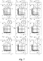
- FIG. 5 shows a highly modularized embodiment of the display device 1 comprising largely self-sufficient, similar panels P i , which are connected to one another via the connecting elements 4 .
- Each panel P i has an associated driver 12 and an associated measuring device 6 consisting of sensors 7 and evaluation unit 8 .
- the section of the image or video signal V relating to the respective panel P i is fed to the drivers 12 from a demultiplexer 17 via a bus 18 .
- the sensors 7 of the panel P i measure the gap widths d i ⁇ 1 , d i both of the left gap S i ⁇ 1 to the neighboring panel P i ⁇ 1 and the right gap S i to the neighboring panel P i+1 , and the evaluation unit 6 determines an associated gap width d i ⁇ 1,m , d i,m for each row R m of the panel P i and sends said gap width to the driver 12 of the panel P i .
- the driver 12 controls the luminous elements 2 of the panel P i by scaling the signal V in order to reduce the gap visibility.
- FIG. 6 shows an alternative, simplified modularization of the display device 1 having panels P i communicating with one another.
- Two adjacent panels P i , P i+1 each here share a measuring device 6 for measuring the gap S i between them.
- the measuring device 6 of the panel P i+1 sends the determined gap widths d i , d i (y) or d i,m of the gap S i via a line 19 to the driver 12 of the neighboring panel P i ⁇ 1 , so that this can also accordingly activate the luminous elements 2 for perception compensation of the gap S i .
- the line 19 could be omitted, and each driver 12 compensates only that gap S i ⁇ 1 for which it has a measuring device 6 .
- FIG. 7 shows a further embodiment of the display device 1 comprising communicating panels P i,j , which are arranged two-dimensionally, that is, not only horizontally but also vertically next to one another.
- the sensors 7 of each panel P i,j measure, for example, the width d i ⁇ 1,j of the gap S i ⁇ 1,j formed with the left neighboring panel P i ⁇ 1,j and the width d i,j+1 of the gap S i,j+1 formed with the lower neighboring panel P i,j+1 (the y and x dependencies or row and column indices m, n of the gap widths d i,j are omitted here for the sake of simplicity, but can be taken into account as described above).
- the panels P i,j send the gap widths d i,j determined thereby via lines 20 to the respective neighboring panel (here: P i,j , P i,j+1 ), with which they form the respective gap, so that the number of measuring devices 6 or sensors 7 can be minimized.
- the rows R m and/or the columns C n of adjacent panels P i ⁇ 1,j , P i,j or P i,j+1 , P i,j may also not be exactly aligned with one another in rows or columns (not shown).
- two or more neighboring panels may adjoin a peripheral side 11 of a panel P i,j .
- two panels P i+1,j can adjoin the peripheral side 11 of the first panel P i,j , which are, for example, only half as high as the first panel P i,j and/or which partially protrude beyond the peripheral side 11 .
- the panels P i,j of the display device 1 do not all need to have the same shape or size, but can also be different, for example, in the form of rectangles of different dimensions.
Landscapes
- Engineering & Computer Science (AREA)
- Physics & Mathematics (AREA)
- General Physics & Mathematics (AREA)
- Theoretical Computer Science (AREA)
- Computer Hardware Design (AREA)
- Multimedia (AREA)
- Human Computer Interaction (AREA)
- General Engineering & Computer Science (AREA)
- Devices For Indicating Variable Information By Combining Individual Elements (AREA)
- Control Of Indicators Other Than Cathode Ray Tubes (AREA)
- Electroluminescent Light Sources (AREA)
Applications Claiming Priority (3)
| Application Number | Priority Date | Filing Date | Title |
|---|---|---|---|
| EP20183454.6 | 2020-07-01 | ||
| EP20183454 | 2020-07-01 | ||
| EP20183454.6A EP3933569B1 (de) | 2020-07-01 | 2020-07-01 | Anzeigevorrichtung, paneel und steuerungsverfahren hiefür |
Publications (2)
| Publication Number | Publication Date |
|---|---|
| US20220005438A1 US20220005438A1 (en) | 2022-01-06 |
| US11488564B2 true US11488564B2 (en) | 2022-11-01 |
Family
ID=71451995
Family Applications (1)
| Application Number | Title | Priority Date | Filing Date |
|---|---|---|---|
| US17/357,538 Active US11488564B2 (en) | 2020-07-01 | 2021-06-24 | Display device having gap width measuring device between panels and control method therefor |
Country Status (3)
| Country | Link |
|---|---|
| US (1) | US11488564B2 (de) |
| EP (1) | EP3933569B1 (de) |
| CN (1) | CN113889015A (de) |
Cited By (3)
| Publication number | Priority date | Publication date | Assignee | Title |
|---|---|---|---|---|
| USD1007452S1 (en) * | 2022-02-10 | 2023-12-12 | C Seed Technologies Gmbh | TV set |
| US20240096274A1 (en) * | 2020-06-30 | 2024-03-21 | Boe Technology Group Co., Ltd. | Display apparatus and display method therefor |
| USD1023991S1 (en) * | 2022-04-27 | 2024-04-23 | KAMARA Werbe und Kommunikations GmbH | Television apparatus |
Families Citing this family (1)
| Publication number | Priority date | Publication date | Assignee | Title |
|---|---|---|---|---|
| US11688364B2 (en) | 2021-05-19 | 2023-06-27 | Apple Inc. | Systems and methods for tile boundary compensation |
Citations (16)
| Publication number | Priority date | Publication date | Assignee | Title |
|---|---|---|---|---|
| US20020122134A1 (en) * | 2001-03-05 | 2002-09-05 | Kalua Kevin A. | Video display array of sealed, modular units |
| US6741222B1 (en) * | 1999-07-13 | 2004-05-25 | Daktronics, Inc. | Panelized/modular electronic display |
| US20050210722A1 (en) * | 2004-02-09 | 2005-09-29 | Graef John T | Foldable electronic display |
| US20110102300A1 (en) * | 2009-11-04 | 2011-05-05 | Christie Digital Systems Usa, Inc. | Tiled display system and improvement therein |
| US20120147463A1 (en) * | 2009-06-19 | 2012-06-14 | Global Bright Media Werbe Gmbh | Foldable display device |
| CN102842285A (zh) | 2012-09-18 | 2012-12-26 | 广东威创视讯科技股份有限公司 | 一种亮度调节方法及led点阵模块、屏幕 |
| WO2013051063A1 (ja) | 2011-10-06 | 2013-04-11 | 三菱電機株式会社 | 画像表示システム、制御装置、及び表示モジュール |
| EP2568464B1 (de) | 2011-09-09 | 2014-04-02 | Global Bright Media Werbe GmbH | Tonnenförmig faltbare und versenkbare Anzeigeeinrichtung |
| US20150002371A1 (en) * | 2013-07-01 | 2015-01-01 | Motorola Solutions, Inc | System and method for automatic aggregation of multiple physical display devices into a single logical display surface |
| US20160224306A1 (en) * | 2015-01-30 | 2016-08-04 | Cirrus Systems, Inc. | Modular Display System with Automatic Locating Features |
| AT515846B1 (de) | 2014-02-12 | 2016-09-15 | C Seed Tech Gmbh | Anzeigevorrichtung |
| US20180005606A1 (en) * | 2016-06-30 | 2018-01-04 | Canon Kabushiki Kaisha | Display device and method of controlling the same |
| US20180139422A1 (en) * | 2016-11-11 | 2018-05-17 | Christie Digital Systems Usa, Inc. | System and method for digital black level blending |
| US20190086724A1 (en) * | 2017-09-15 | 2019-03-21 | Innolux Corporation | Display device |
| WO2019066594A1 (ko) | 2017-09-29 | 2019-04-04 | 삼성전자주식회사 | 디스플레이 장치 및 그 제어 방법 |
| US20200211155A1 (en) * | 2018-07-13 | 2020-07-02 | Boe Technology Group Co., Ltd. | Image processing method and device for spliced panel, and spliced panel |
Family Cites Families (4)
| Publication number | Priority date | Publication date | Assignee | Title |
|---|---|---|---|---|
| US8860632B2 (en) * | 2008-09-08 | 2014-10-14 | Qualcomm Incorporated | Multi-panel device with configurable interface |
| US9529563B2 (en) * | 2014-09-30 | 2016-12-27 | X Development Llc | Masking mechanical separations between tiled display panels |
| DE102015219789A1 (de) * | 2015-10-13 | 2017-04-13 | Osram Gmbh | Leuchtdichteregulierung an Randbereichen |
| CN106157826B (zh) * | 2015-12-29 | 2019-10-18 | 深圳市欧立光电技术有限公司 | 一种模块化led显示屏 |
-
2020
- 2020-07-01 EP EP20183454.6A patent/EP3933569B1/de active Active
-
2021
- 2021-06-24 US US17/357,538 patent/US11488564B2/en active Active
- 2021-06-28 CN CN202110718783.7A patent/CN113889015A/zh active Pending
Patent Citations (19)
| Publication number | Priority date | Publication date | Assignee | Title |
|---|---|---|---|---|
| US6741222B1 (en) * | 1999-07-13 | 2004-05-25 | Daktronics, Inc. | Panelized/modular electronic display |
| US20020122134A1 (en) * | 2001-03-05 | 2002-09-05 | Kalua Kevin A. | Video display array of sealed, modular units |
| US20050210722A1 (en) * | 2004-02-09 | 2005-09-29 | Graef John T | Foldable electronic display |
| US20120147463A1 (en) * | 2009-06-19 | 2012-06-14 | Global Bright Media Werbe Gmbh | Foldable display device |
| EP2443621B1 (de) | 2009-06-19 | 2015-03-04 | Global Bright Media Werbe GmbH | Faltbare anzeigevorrichtung |
| US20110102300A1 (en) * | 2009-11-04 | 2011-05-05 | Christie Digital Systems Usa, Inc. | Tiled display system and improvement therein |
| EP2568464B1 (de) | 2011-09-09 | 2014-04-02 | Global Bright Media Werbe GmbH | Tonnenförmig faltbare und versenkbare Anzeigeeinrichtung |
| WO2013051063A1 (ja) | 2011-10-06 | 2013-04-11 | 三菱電機株式会社 | 画像表示システム、制御装置、及び表示モジュール |
| CN102842285B (zh) | 2012-09-18 | 2015-06-24 | 广东威创视讯科技股份有限公司 | 一种亮度调节方法及led点阵模块、屏幕 |
| CN102842285A (zh) | 2012-09-18 | 2012-12-26 | 广东威创视讯科技股份有限公司 | 一种亮度调节方法及led点阵模块、屏幕 |
| US20150002371A1 (en) * | 2013-07-01 | 2015-01-01 | Motorola Solutions, Inc | System and method for automatic aggregation of multiple physical display devices into a single logical display surface |
| AT515846B1 (de) | 2014-02-12 | 2016-09-15 | C Seed Tech Gmbh | Anzeigevorrichtung |
| US20160224306A1 (en) * | 2015-01-30 | 2016-08-04 | Cirrus Systems, Inc. | Modular Display System with Automatic Locating Features |
| US20180005606A1 (en) * | 2016-06-30 | 2018-01-04 | Canon Kabushiki Kaisha | Display device and method of controlling the same |
| US20180139422A1 (en) * | 2016-11-11 | 2018-05-17 | Christie Digital Systems Usa, Inc. | System and method for digital black level blending |
| US20190086724A1 (en) * | 2017-09-15 | 2019-03-21 | Innolux Corporation | Display device |
| WO2019066594A1 (ko) | 2017-09-29 | 2019-04-04 | 삼성전자주식회사 | 디스플레이 장치 및 그 제어 방법 |
| US20200251048A1 (en) * | 2017-09-29 | 2020-08-06 | Samsung Electronics Co., Ltd. | Display apparatus and method of controlling the same |
| US20200211155A1 (en) * | 2018-07-13 | 2020-07-02 | Boe Technology Group Co., Ltd. | Image processing method and device for spliced panel, and spliced panel |
Non-Patent Citations (1)
| Title |
|---|
| Extended European Search Report received for European Patent Application No. 20183454.6, dated Nov. 24, 2020, 16 pages (9 pages of Official Copy and 7 pages of English Translation). |
Cited By (5)
| Publication number | Priority date | Publication date | Assignee | Title |
|---|---|---|---|---|
| US20240096274A1 (en) * | 2020-06-30 | 2024-03-21 | Boe Technology Group Co., Ltd. | Display apparatus and display method therefor |
| US12087217B2 (en) * | 2020-06-30 | 2024-09-10 | Boe Technology Group Co., Ltd. | Display apparatus and display method therefor |
| USD1007452S1 (en) * | 2022-02-10 | 2023-12-12 | C Seed Technologies Gmbh | TV set |
| USD1023991S1 (en) * | 2022-04-27 | 2024-04-23 | KAMARA Werbe und Kommunikations GmbH | Television apparatus |
| USD1026842S1 (en) * | 2022-04-27 | 2024-05-14 | KAMARA Werbe und Kommunikations GmbH | Television apparatus |
Also Published As
| Publication number | Publication date |
|---|---|
| US20220005438A1 (en) | 2022-01-06 |
| EP3933569B1 (de) | 2025-08-27 |
| EP3933569A1 (de) | 2022-01-05 |
| CN113889015A (zh) | 2022-01-04 |
| EP3933569C0 (de) | 2025-08-27 |
Similar Documents
| Publication | Publication Date | Title |
|---|---|---|
| US11488564B2 (en) | Display device having gap width measuring device between panels and control method therefor | |
| KR102224096B1 (ko) | 표시장치 | |
| US9437127B2 (en) | Device and method for displaying image, device and method for supplying power, and method for adjusting brightness of contents | |
| US8248359B2 (en) | Display apparatus and driving method therefor | |
| US9001167B2 (en) | Display panel having crossover connections effecting dot inversion | |
| CN110610680A (zh) | 显示方法、显示面板及装置、亮度校正方法、存储介质 | |
| US20100033649A1 (en) | Surface light source device and liquid crystal display unit | |
| KR100420158B1 (ko) | 영상표시장치 및 그의 구동방법 | |
| US20030132901A1 (en) | Field sequential color display device | |
| US20090303171A1 (en) | Method of local dimming of light source, light source apparatus for performing the method and display apparatus having the light source apparatus | |
| KR20080005966A (ko) | 리어 프로젝션 어레이 시스템을 이용하는 로우 프로파일,대형 스크린 디스플레이 | |
| JP4292242B2 (ja) | 帰還回路部を備えた液晶表示装置 | |
| US20190228722A1 (en) | Display apparatus including a luminance compensating part and method of driving the same | |
| RU2457552C1 (ru) | Устройство управления для жидкокристаллического дисплейного устройства, жидкокристаллическое дисплейное устройство, способ управления жидкокристаллическим дисплейным устройством, телевизионный приемник | |
| JP2003520994A (ja) | 大形の堅固なモノリシックのおよびモノリシック様の、広い観察角をもつamlcdディスプレイ | |
| US8259127B2 (en) | Systems and methods for reducing desaturation of images rendered on high brightness displays | |
| KR100625361B1 (ko) | 표시 장치의 구동 회로, 구동 방법, 표시 장치 및 투사형표시 장치 | |
| KR20190126664A (ko) | 서브픽셀 렌더링 디스플레이 장치 및 그의 영상 처리 방법 | |
| KR102141032B1 (ko) | 영상 표시 방법 및 이를 구동하는 표시 장치 | |
| JP5326561B2 (ja) | 液晶装置の駆動方法、液晶装置および電子機器 | |
| KR20230040124A (ko) | 타일링 디스플레이 장치 및 디스플레이 구동 방법 | |
| JP2003323130A (ja) | 駆動用半導体装置及び表示装置ならびに輝度バランス調整方法 | |
| US7786969B2 (en) | Liquid crystal display device and driving method of the same | |
| WO2013018822A1 (ja) | 画像表示装置および画像表示方法 | |
| JP2022024567A (ja) | 表示システム |
Legal Events
| Date | Code | Title | Description |
|---|---|---|---|
| FEPP | Fee payment procedure |
Free format text: ENTITY STATUS SET TO UNDISCOUNTED (ORIGINAL EVENT CODE: BIG.); ENTITY STATUS OF PATENT OWNER: SMALL ENTITY |
|
| AS | Assignment |
Owner name: KAMARA WERBE UND KOMMUNIKATIONS GMBH, AUSTRIA Free format text: ASSIGNMENT OF ASSIGNORS INTEREST;ASSIGNORS:SWATEK, ALEXANDER;STOEGER, ELMAR;KIRSCHNER, MARKUS;AND OTHERS;SIGNING DATES FROM 20210623 TO 20210624;REEL/FRAME:056667/0909 |
|
| FEPP | Fee payment procedure |
Free format text: ENTITY STATUS SET TO SMALL (ORIGINAL EVENT CODE: SMAL); ENTITY STATUS OF PATENT OWNER: SMALL ENTITY |
|
| STPP | Information on status: patent application and granting procedure in general |
Free format text: NON FINAL ACTION MAILED |
|
| STPP | Information on status: patent application and granting procedure in general |
Free format text: RESPONSE TO NON-FINAL OFFICE ACTION ENTERED AND FORWARDED TO EXAMINER |
|
| STPP | Information on status: patent application and granting procedure in general |
Free format text: FINAL REJECTION MAILED |
|
| STPP | Information on status: patent application and granting procedure in general |
Free format text: ADVISORY ACTION MAILED |
|
| STPP | Information on status: patent application and granting procedure in general |
Free format text: DOCKETED NEW CASE - READY FOR EXAMINATION |
|
| STPP | Information on status: patent application and granting procedure in general |
Free format text: NOTICE OF ALLOWANCE MAILED -- APPLICATION RECEIVED IN OFFICE OF PUBLICATIONS |
|
| STPP | Information on status: patent application and granting procedure in general |
Free format text: PUBLICATIONS -- ISSUE FEE PAYMENT VERIFIED |
|
| STCF | Information on status: patent grant |
Free format text: PATENTED CASE |