US11479290B2 - Steering system having a reluctance brake - Google Patents
Steering system having a reluctance brake Download PDFInfo
- Publication number
- US11479290B2 US11479290B2 US16/962,266 US201916962266A US11479290B2 US 11479290 B2 US11479290 B2 US 11479290B2 US 201916962266 A US201916962266 A US 201916962266A US 11479290 B2 US11479290 B2 US 11479290B2
- Authority
- US
- United States
- Prior art keywords
- steering
- holding
- holding brake
- brake
- steering shaft
- Prior art date
- Legal status (The legal status is an assumption and is not a legal conclusion. Google has not performed a legal analysis and makes no representation as to the accuracy of the status listed.)
- Active, expires
Links
Images


Classifications
-
- B—PERFORMING OPERATIONS; TRANSPORTING
- B62—LAND VEHICLES FOR TRAVELLING OTHERWISE THAN ON RAILS
- B62D—MOTOR VEHICLES; TRAILERS
- B62D5/00—Power-assisted or power-driven steering
- B62D5/001—Mechanical components or aspects of steer-by-wire systems, not otherwise provided for in this maingroup
- B62D5/005—Mechanical components or aspects of steer-by-wire systems, not otherwise provided for in this maingroup means for generating torque on steering wheel or input member, e.g. feedback
- B62D5/006—Mechanical components or aspects of steer-by-wire systems, not otherwise provided for in this maingroup means for generating torque on steering wheel or input member, e.g. feedback power actuated
-
- B—PERFORMING OPERATIONS; TRANSPORTING
- B62—LAND VEHICLES FOR TRAVELLING OTHERWISE THAN ON RAILS
- B62D—MOTOR VEHICLES; TRAILERS
- B62D5/00—Power-assisted or power-driven steering
- B62D5/001—Mechanical components or aspects of steer-by-wire systems, not otherwise provided for in this maingroup
-
- B—PERFORMING OPERATIONS; TRANSPORTING
- B62—LAND VEHICLES FOR TRAVELLING OTHERWISE THAN ON RAILS
- B62D—MOTOR VEHICLES; TRAILERS
- B62D5/00—Power-assisted or power-driven steering
- B62D5/001—Mechanical components or aspects of steer-by-wire systems, not otherwise provided for in this maingroup
- B62D5/005—Mechanical components or aspects of steer-by-wire systems, not otherwise provided for in this maingroup means for generating torque on steering wheel or input member, e.g. feedback
-
- H—ELECTRICITY
- H02—GENERATION; CONVERSION OR DISTRIBUTION OF ELECTRIC POWER
- H02K—DYNAMO-ELECTRIC MACHINES
- H02K1/00—Details of the magnetic circuit
-
- H—ELECTRICITY
- H02—GENERATION; CONVERSION OR DISTRIBUTION OF ELECTRIC POWER
- H02K—DYNAMO-ELECTRIC MACHINES
- H02K49/00—Dynamo-electric clutches; Dynamo-electric brakes
- H02K49/06—Dynamo-electric clutches; Dynamo-electric brakes of the synchronous type
Definitions
- the present disclosure generally relates to a steering system.
- the present invention relates to a steering system having the features of the preamble of claim 1 .
- Electromechanical power steering systems in motor vehicles support the steering force which is applied by the driver.
- the steering force which the driver specifies by means of a steering wheel is directed into a torsion bar which rotates in a force-dependent fashion.
- This torque is measured by a sensor which passes on said information to an electronic control unit. This in turn provides the electric servomotor with precise commands as to which additional torque is to be applied to the steering system.
- Such steering stops are known, for example, from documents DE 10 2008 045 195 A1 and DE 10 2013 014 138 B3. Both documents disclose a sliding block which is guided in a slotted link and which moves into a mechanical block position when a predefined maximum movement is reached.
- variable coupling between the lock angle of the steering wheel and the corresponding steering angle lock of a wheel is not possible. It is therefore desirable, for example, that a specific lock angle brings about a different steering angle lock in the case of slow travel than in the case of fast travel.
- various approaches to a solution are known in the prior art, including mechanically variable end stops such as, for example, in DE102013014135B3 and JP2008285045A.
- FIG. 1 is a schematic view of a steer-by-wire steering system.
- FIG. 2 is a schematic view of a reluctance brake with a current-excited stator.
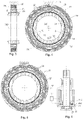
- FIG. 3 is a longitudinal section and a cross sectional view of a reluctance brake in a holding position.
- FIG. 4 is a longitudinal section and a cross sectional view of a reluctance brake in a holding position.
- FIG. 5 is a cross sectional view of the reluctance brake shown in FIG. 3 , in an open position.
- FIG. 6 is a schematic view of a reluctance brake with a current-excited rotor.
- FIG. 7 is a longitudinal sectional view of a reluctance brake which is embodied as a double rotor.
- FIG. 8 is a cross sectional view of the reluctance brake in FIG. 7 in a holding position.
- FIG. 9 is a cross sectional view of the reluctance brake in FIG. 7 in an open position.
- FIG. 10 is a schematic view of a steering-wheel-side reluctance brake with a current-excited inner ring as a stator.
- FIG. 11 is a schematic view of a steering-wheel-side reluctance brake with a current-excited inner ring as a rotor.
- FIG. 12 is a schematic view of a reluctance brake, remote from the steering wheel, with a current-excited inner ring as a stator.
- FIG. 13 is a schematic view of a reluctance brake, remote from the steering wheel, with a current-excited inner ring as a rotor.
- FIGS. 14 a - d are views of tooth shapes.
- FIG. 15 a is a cross sectional view of an embodiment of a reluctance brake with a U-shaped coil carrier.
- FIG. 15 b is a cross sectional view of an embodiment of a reluctance brake with a U-shaped coil carrier.
- FIG. 15 c is a cross sectional view of an embodiment of a reluctance brake with a U-shaped coil carrier.
- FIG. 16 a is a cross sectional view of an embodiment of a reluctance brake with laminations.
- FIG. 16 b is a cross sectional view of an embodiment of a reluctance brake with laminations.
- FIGS. 17 a -c are cross sectional views of an embodiment of a reluctance brake with oblique components.
- FIG. 18 is a cross sectional view of a further embodiment of a reluctance brake.
- the present invention relates to a steering system.
- a steering system for motor vehicles comprising a steering actuator which acts on the steered wheels, is electronically controlled in accordance with a driver's steering request and acts on the steered wheels by means of a steering gear, and an actuator device which transmits reactions to a steering shaft which is connected to the steering wheel, wherein the steering system comprises a holding brake which can be activated electrically and can assume two positions.
- the holding brake can therefore make available end stops for the steering system. These end stops are completely flexible, since the predefined rotational angle can be selected, for example, in accordance with the speed.
- the actuator device has the function of providing the driver with feedback about the situation of the steering system and his surroundings.
- the intention is that the driver will, as it were, feel the road and the state of the steering system.
- Feedback can be provided through direct mechanical coupling of the wheels and of the steering wheel.
- the feedback is preferably provided by means of an electric feedback actuator, which in the case of mechanical coupling of the wheels and steering wheel can boost or superimpose the feedback, and in the case of steer-by-wire systems it simulates a feedback response without mechanical feedback.
- the holding brake is preferably a reluctance brake: in this context, the principle of minimization of a magnetic resistance is utilized.
- a magnetic system seeks to reduce magnetic resistance to increase the inductivity of the system.
- the reluctance force is used to block the steering shaft.
- the holding brake is preferably embodied in such a way that when the holding brake is energized it assumes a holding position by minimization of a magnetic resistance between a first element, which is rotatably connected to the steering shaft, and a second element, which is fixedly connected to the housing.
- This has the advantage that in the switched-off state the brake does not have any friction or ripple.
- the brake does not lock as a result of icing up or swarf.
- the coil bodies are energized with a single phase. This means that the same phase is applied to all the coil bodies.
- a control device for controlling the coil bodies can be a very simple design, since it requires only one output to the coil bodies.
- the means of energizing the coil bodies can be of a non-controllable design. It may be advantageously sufficient to implement the control for the current in such a way that it can only be switched on or off. This has the advantage of a simple actuation circuit.
- the holding force of the holding brake is preferably controllable, i.e. by means of the current strength and/or voltage.
- an adjustable holding force can be implemented. This can be consciously selected to be lower in an individual case than a torque which is input externally, e.g. via a steering wheel.
- rotation with ripples can be achieved, which can, for example, indicate an incorrect direction of rotation to the driver.
- the holding brake is particularly preferably controlled in such a way that a soft steering stop can be implemented, so that e.g. the force which is applied by the holding brake rises slowly in the vicinity of the predefined maximum steering angle, and the maximum holding force is not reached until when the maximum steering angle is reached.
- the current and/or voltage can be selected in accordance with the rotor position.
- a rotating or rotatable element and stationary element have at least one pair of faces which are opposite one another or faces which are opposite one another in pairs and have profiling (profile pair).
- the profiling is provided on both faces.
- the profiling is preferably applied only on magnetically active parts.
- the profiling is preferably embodied in a complementary fashion.
- the holding brake can have one or more pairs of faces with profiling. As a result, a relatively large active magnetic area can be obtained.
- the profiling is preferably embodied as a toothing arrangement.
- the number of teeth of each face of a pair of faces is preferably the same. In this way, when energization occurs, a large number of uniquely defined preferred positions with minimum reluctance is always available.
- the ratio of the number of teeth of one face to the other face of a pair of faces can, however, always be any integer. This permits the number of preferred positions to be easily adapted.
- the pairs of faces with the profiling preferably run perpendicularly and/or horizontally and/or obliquely with respect to a rotational axis of the holding brake. In this way, adaptation to a large number of installation space situations is possible.
- the holding brake is preferably arranged coaxially with respect to the steering shaft.
- the holding brake is preferably arranged in one housing together with the actuator device and as a result in a particularly space-saving fashion.
- the holding brake preferably does not have more than three coil bodies, and preferably has two coil bodies, particularly preferably has precisely one coil body. A small number of coil bodies reduces the expenditure on manufacture.
- the coil or the coils can run concentrically with respect to the rotational axis of the holding brake (annular coil). This is advantageous because annular coils can be pre-wound before insertion into a rotor or stator.
- the coils can also be embodied as concentric windings about one stator foot each.
- the holding brake has two elements, a rotating element and a stationary element.
- One of these two elements preferably does not have a coil body.
- This element is referred to below also as an element without a coil or a body without a coil.
- the other element preferably has at least one coil body.
- This element is also referred to below as an element or body with a coil.
- the element with a coil can be embodied in one or more pieces.
- the element without a coil can be embodied in one or more pieces.
- the element without a coil can be permanently magnetized or partially magnetized. It is also possible for only individual parts of the element which is without a coil and is embodied in multiple parts to be magnetized.
- the magnetization direction of the magnetic field can be perpendicular with respect to the rotational axis of the holding brake or else parallel thereto depending on the coil arrangement in a plane.
- the holding brake can also comprise permanent magnets.
- Permanent magnetization increases the magnetic flux density of the system. In this way a higher energy density, and consequently a greater holding force, can be implemented.
- the holding brake therefore has ripples.
- the holding brake can have an energization algorithm for compensating the ripples.
- the holding brake has a holding ring which abuts against the steering shaft, an inner ring, which is connected in a rotationally fixed fashion to the steering shaft by means of the holding ring, and an outer ring, which surrounds the inner ring circumferentially and is connected to the housing.
- the holding brake therefore acts directly on the steering shaft via the holding ring.
- the outer or the inner ring have an iron ring with a U-shaped cross section, which has received a coil, which can be energized, in an annular groove.
- the respective other ring is preferably an iron ring which is rectangular in cross section.
- the inner ring has, on the outer face, and the outer ring has, on the inner face, a toothing arrangement, which toothing arrangements are complementary. The toothing arrangements do not engage in one another here. There is an air gap between the inner ring and the outer ring.
- the holding brake has an inner ring with a U-shaped cross section and with an outer-circumferential and an inner-circumferential toothing arrangement, wherein a coil which can be energized is received in an annular groove between the limbs of the inner ring.
- the holding brake has an outer ring with a U-shaped cross section and with a toothing arrangement on the inner sides of both limbs, so that the inner ring is received between the two limbs of the outer ring, and two air gaps are available for minimizing the magnetic resistance.
- the available holding force of the holding brake can as a result be increased with respect to the first embodiment.
- the inner ring which can be energized is connected to the housing, wherein the outer ring is attached to the steering shaft, or the inner ring which can be energized can be connected to the outside of the steering shaft, wherein the outer ring is then attached to the housing.
- the embodiments have in common that the limbs of the rings which are formed with a U-shaped cross section preferably extend in the direction of the longitudinal axis of the steering shaft and are arranged concentrically with respect thereto. Furthermore, it is advantageous if the inner ring and the outer ring are generally formed from iron.
- the coil is preferably attached in the annular groove with a grouting agent. It is preferably energized by means of a control unit according to requirements. It is advantageous here if this control unit has a device, comprising a full bridge circuit, for demagnetizing the holding brake.
- a steering stop can be formed in the feedback actuator using the holding device.
- an electromagnetic braking and holding device comprises a stator and a rotor which are mounted in a rotational fashion with respect to one another.
- the stator and rotor have faces which are turned toward one another and which form a non-constant air gap through profiling.
- Either the stator or the rotor has here one or more coils, wherein the corresponding other coil is a body without a coil. All the coils are energized with a single phase.
- the coil or coils is/are designed to delay or block (reluctance brake) a relative movement between the stator and rotor when energization occurs.
- the electromagnetic braking and holding device can be switched between an open position and a holding position, which block rotation in the holding position when a predefined rotational angle of the rotor with respect to the stator is exceeded, and release rotation between the stator and the rotor in the open position.
- the braking and holding device preferably has a multiplicity of preferred positions, distributed over the circumference, with minimum reluctance only when energization occurs.
- the electromagnetic braking and holding device can have a multiplicity of pairs of faces with profiling.
- the pairs of faces can be arranged horizontally and/or perpendicularly and/or obliquely with respect to the rotational axis of the rotor.
- the electromagnetic braking and holding device preferably has precisely one single coil. This is preferably located concentrically around the rotational axis of the rotor.
- the holding brake can be of modular design or can be used in a modular fashion. As a result, a desired holding force can be easily implemented by the multiple use of identical parts.
- FIG. 1 shows a steer-by-wire steering system 1 .
- a rotational angle sensor (not illustrated) is attached to a steering shaft 2 , which sensor detects the driver's steering angle which is applied by rotating a steering input means 3 , which is embodied as a steering wheel in the example. However, it is additionally or alternatively also possible to register a steering toque.
- a feedback actuator 4 is attached to the steering shaft 2 , which feedback actuator 4 serves to simulate the reactions of the roadway 5 on the steering wheel 3 and therefore to provide the driver with feedback about the steering and driving behavior of the vehicle.
- the driver's steering request is transmitted to a control unit 7 via the rotational angle a, measured by the rotational angle sensor, of the steering shaft 2 via signal lines 6 .
- the control unit 7 transmits the driver's steering request via a signal line 8 to an electric steering actuator 9 which controls the position of the steered wheels 10 .
- the steering actuator 9 acts indirectly on the steered wheels 10 via a steering-rod steering gear 11 , such as for example a toothed rack steering gear, as well as via track rods 12 and other components.
- the control unit 7 preferably also performs the actuation of the feedback actuator 4 and the actuation of a holding brake 13 via a signal line 14 .
- the holding brake 13 is designed to lock rotation of the steering shaft 2 , i.e. it provides the necessary holding force to prevent rotation of the steering shaft 2 , when a predefined rotational angle of the steering shaft 2 is exceeded.
- the holding brake 13 is preferably embodied integrally with the feedback actuator 4 in a common housing 16 .
- the control unit 7 also receives signals of sensors 18 from the steering gear 11 via a signal line 17 .
- FIGS. 2 and 3 illustrate embodiments of the holding brake 13 .
- the steering shaft 2 has, at one end, a receptacle 19 for attaching the steering shaft 2 to the steering wheel (not illustrated).
- the steering shaft 2 is rotationally arranged at the end near to the steering wheel and at the end remote from the steering wheel, in the housing 16 .
- the housing 16 surrounds the feedback actuator 4 and the holding brake 13 .
- the feedback actuator 4 has a rotor 20 which is connected in a rotationally fixed fashion to the steering shaft 2 , and a stator 21 which surrounds the rotor 20 , which rotor and stator are part of a servomotor.
- the stator 21 has a stator groove 22 which extends in a longitudinal section along the steering shaft 2 and in which the electrical windings 23 are inserted.
- the control unit 7 is connected to the feedback actuator 4 and actuates the energization of the windings 23 .
- the holding brake 13 is arranged on the side of the feedback actuator 4 which is remote from the steering wheel. It surrounds the steering shaft 2 concentrically.
- the holding brake 13 has a holding ring 24 which abuts against the steering shaft 2 and which connects the steering shaft 2 in a rotationally fixed fashion to an inner ring 25 .
- the inner ring 25 is surrounded by an outer ring 26 which is connected to the housing 16 .
- the holding brake 13 operates according to the reluctance principle.
- the method of functioning of the holding brake 13 arises from the minimization of the magnetic resistance, also referred to as reluctance.
- the outer ring 26 (illustrated in the embodiment in FIGS. 2 to 5 ) has an iron ring which has a U-shaped cross section and has received a coil 28 in an annular groove 27 .
- the limbs of the outer ring 26 extend here in the direction of the longitudinal axis 200 of the steering shaft 2 and are arranged concentrically with respect thereto.
- the coil 28 is preferably attached to a grouting agent in the annular groove 27 .
- the turns 29 of the coil 28 run in the circumferential direction around the longitudinal axis 200 of the steering shaft 2 .
- the turns 29 are preferably formed from copper wire.
- the outer ring 26 is connected to the control unit 7 and can be energized via it.
- the inner ring 25 is also an iron ring.
- the inner ring 25 has profiling 31 on the outer face 30
- the outer ring 26 has profiling 32 on its inner face 33 .
- the pair of faces are configured with profiling in such a way that the profiling 31 and the profiling 32 are configured to correspond to one another.
- An air gap 34 is provided between the outer ring 26 and the inner ring 25 so that the inner ring 25 can rotate with the steering shaft 2 , while the outer ring 26 is held on the housing 16 in a positionally fixed fashion.
- the technically necessary air gap 34 is given the smallest possible dimensions.
- the profiling 31 , 32 preferably comprises teeth 35 which are preferably spaced apart evenly along the circumference of the inner ring 25 and outer ring 26 and extend parallel to the longitudinal axis 200 of the steering shaft 2 .
- the reluctance force arises at the surface between two materials with different permeability (e.g. iron and air).
- the resulting reluctance force acts in such a way that it wishes to reduce the difference in reluctance.
- the coil 28 When the coil 28 is energized, the inner ring 25 therefore turns in the outer ring 26 until the reluctance is minimal. In which situation, the magnetic resistance along the paths is then lowest if the air gap 34 between the inner ring 25 and the outer ring 26 is minimal.
- the reluctance is minimal if the teeth 35 of the inner ring 25 and of the outer ring 26 are located opposite one another.
- the holding force is so large that the rotation of the steering shaft 2 is blocked.
- the holding position of the holding brake 13 is illustrated in FIG. 4 .
- the control unit 7 also has a device for demagnetizing the reluctance brake 13 .
- a full bridge circuit is preferably provided for this in the control unit 7 .
- the magnetic flux between the inner ring 25 and the outer ring 26 is interrupted through demagnetization.
- the braking effect of the holding brake 13 is therefore cancelled and the inner ring 25 can rotate freely with the steering shaft 2 .
- FIG. 5 shows an opened state of the holding brake 13 .
- the holding brake 13 illustrated in FIG. 6 corresponds in terms of the principle to the embodiment described above.
- the difference is that the inner ring 250 of the holding brake 13 is an iron ring with a U-shaped cross section which has received a coil 28 in an annular groove 27 .
- the inner ring 250 connected in a rotationally fixed fashion to the steering shaft, of the holding brake 13 , and not the outer ring 260 which is an iron ring with a rectangular cross section, is energized.
- the holding brake 13 can have an inner ring 251 which is connected to the housing 16 and has an outer-circumferential and inner-circumferential toothing arrangement 36 , 37 and an outer ring 261 which is complementary thereto, in the shape of a U with a toothing arrangement 38 , 39 on the inner sides of the two limbs.
- This embodiment with two air gaps 40 , 41 between the inner ring 251 and the outer ring 261 is illustrated in FIGS. 7 to 13 . It is also referred to as a “double rotor”.
- the inner ring 251 has an iron ring with a coil. Energization of the inner ring 251 brings about minimization of the magnetic resistance between the inner ring 251 and the outer ring 261 .
- the outer ring 261 covers the inner ring 251 on the side near to the annular groove. The inner ring 251 is therefore completely received in the outer ring 261 .
- An air gap 40 , 41 is formed in each case between a limb of the inner ring 251 and a limb of the outer ring 261 .
- the profiling or toothing arrangement on the two rings 251 , 261 is embodied in such a way that the position of the pairs of teeth of the first air gap 40 and the position of the pairs of teeth of the second air gap 41 are synchronous, i.e. if the pairs of teeth of the first air gap 40 are opposite one another, the pairs of teeth of the second air gap 41 are also simultaneously opposite one another.
- the holding brake 13 is illustrated in the holding position.
- FIG. 9 shows an open position of the holding brake 13 .
- FIGS. 10 and 11 show two embodiments of a holding brake 13 with a double rotor, wherein the holding brake 13 is arranged at the steering-wheel-side end of the steering shaft 2 .
- the outer ring 262 is attached to a steering shaft 2 .
- the inner ring 252 which can be energized is connected to the housing 16 .
- the inner ring 253 which can be energized is connected to the outside of the steering shaft 2 , and the outer ring 263 is attached to the housing 16 .
- FIGS. 12 and 13 two embodiments of a holding brake 13 with a double rotor are illustrated, wherein the holding brake 13 is arranged at that end of the steering shaft 2 which is remote from the steering wheel.
- the inner ring 254 which can be energized is connected to the housing 16 in FIG. 12
- the outer ring 264 is attached to the steering shaft 2 .
- the inner ring 255 which can be energized is connected to the outside of the steering shaft 2
- the outer ring 265 is connected to the housing 16 . Since the holding brake is arranged in both cases in the direct vicinity of the feedback actuator 4 , the outer ring 264 , 265 points away with its open side from the feedback actuator 4 .
- the inner ring 254 , 255 therefore lies on the side which is remote from the feedback actuator in the outer ring 264 , 265 .
- the rear wall 43 of the outer ring 264 , 265 protects the holding brake 13 against electromagnetic fields which are generated by the feedback actuator 4 .
- FIGS. 14 a - d show different tooth shapes for use in a reluctance brake.
- a flat toothing arrangement of an inner ring 25 and an outer ring 26 is shown in outline, wherein in FIG. 14 a the tooth face 36 is embodied in a round fashion, while in FIG. 15 b it is embodied in a flat fashion.
- a pointed tooth arrangement is present in FIG. 14 c .
- FIG. 14 d a corrugated toothing arrangement.
- FIGS. 15 a -17 c show various embodiments of reluctance brakes in cross section, wherein a complete illustration has been dispensed with. Accordingly, in each case only one half of a complete cross section can be seen.
- FIG. 15 a illustrates a U-in-U shape, as has already been described above in more detail in the statements relating to the “double rotor”.
- the reluctance brake has a stationary part 26 and a rotating part 25 , wherein one of these parts comprises a coil 28 which can be energized.
- the role of the parts as stationary or rotating can be basically interchanged.
- the rotational axis (not shown) is located in the horizontal of the plane of the drawing, underneath or else above the illustrated cross-sectional half, that is to say parallel to the limbs of the U-shaped parts.
- the parts have profiling 31 , 32 (pair of faces with profiling), on selected sides facing one another, there being an air gap presented between profiling 31 and profiling 32 .
- the attachment of the parts to, for example, a steering shaft or a housing is indicated here by means of holding parts 37 .
- the holding parts are each attached here to the outside of the U-shaped parts 25 , 26 . Another position of the holding parts is conceivable.
- the holding parts are preferably made of non-magnetic material, while the parts 25 , 26 are made of magnetic material.
- FIG. 15 a The statements made with respect to FIG. 15 a apply basically also to the following explanations in respect of drawings 15 b - 17 c, so that only the most important differences are discussed.
- FIG. 15 b shows an extended U-in-I shape in which one part is constructed in a U shape and the other part is constructed in an I shape.
- the groove which forms the U shape is for the most part closed off at its opening. Therefore, there are two different profiling pairs 31 , 32 and 310 , 320 , which can be embodied in the same way or in different ways.
- FIG. 15 c shows a double C-in-double-I shape, which in contrast to FIG. 15 b has a third and fourth profiling pair 311 , 321 and 312 , 322 .
- FIG. 16 a shows a variant in which the profiling pairs 31 , 32 are embodied in the manner of a lamination.
- the profiling pairs are embodied perpendicularly with respect to the rotational axis of the reluctance brake.
- FIG. 16 b shows a variant in which, in contrast to FIG. 16 a , the profiling pairs 31 , 32 do not extend perpendicularly but rather parallel to the rotational axis.
- FIGS. 17 a - c show variants with a stationary part and/or rotational part which are/is divided diagonally with respect to the rotational axis. This generates profiling pairs in at least two planes, here parallel and perpendicular with respect to the rotational axis. Another position, for example oblique position of the profiling pairs with respect to the rotational axis is possible.
- FIG. 17 a shows a double L-in-double-L variant.
- FIG. 17 b shows a variant with a round design.
- FIG. 16 c shows a double L-in-double-L shape in which the inner part is secured by means of a holding part which is made to extend outward through the outer part 370 .
- FIG. 18 shows the reluctance brake which is related to the stepping motor and has a corresponding number of teeth 35 of the rotating part 25 and stationary part 26 .
- the stationary part has a multiplicity of coil bodies 28 which can be energized.
- this embodiment has, by virtue of the multiplicity of coils, specific magnetic poles in the part 26 .
- the number and the shape of the teeth of the inner ring and the outer ring can be different.
- the tooth positions are preferably asynchronous, i.e. the pairs of teeth of the first air gap overlap, the pairs of teeth of the second air gap do not overlap or only do so slightly. This increases the number of possible latching positions without increasing the number of teeth.
- the holding brake can generally be provided inside or outside the housing.
- Teeth can have a corrugated shape, be pointed or flat, or have a mixed shape of these types or some other special shape.
- the standing part and the rotating part are preferably fabricated by powder-metallurgical means. They are composed, for example, from non-insulated, powder-metallurgical substances, for example powder-metallurgically magnetic substances, powder-metallurgically soft-magnetic substances, sintered magnetic substances, sintered soft-magnetic substances. However, they can also be composed of fully or partially insulated powder-metallurgical substances, such as for example non-sintered soft-magnetic substances (e.g. glass crystalline multifunction substances (GCM) or soft-magnetic composites (SMC)) or injection molding plastic with a high proportion of magnetic powder.
- non-sintered soft-magnetic substances e.g. glass crystalline multifunction substances (GCM) or soft-magnetic composites (SMC)
- injection molding plastic with a high proportion of magnetic powder.
- the non-magnetized parts for example holding parts or fasteners consist e.g. of copper, aluminum or a polymer substance.
- the coil material can preferably be aluminum or copper.
Landscapes
- Engineering & Computer Science (AREA)
- Chemical & Material Sciences (AREA)
- Combustion & Propulsion (AREA)
- Transportation (AREA)
- Mechanical Engineering (AREA)
- Power Engineering (AREA)
- Braking Arrangements (AREA)
- Power Steering Mechanism (AREA)
Abstract
Description
Claims (20)
Applications Claiming Priority (3)
| Application Number | Priority Date | Filing Date | Title |
|---|---|---|---|
| DE102018102216.6 | 2018-02-01 | ||
| DE102018102216.6A DE102018102216A1 (en) | 2018-02-01 | 2018-02-01 | Steering system with reluctance brake |
| PCT/EP2019/052159 WO2019149713A1 (en) | 2018-02-01 | 2019-01-30 | Steering system having a reluctance brake |
Publications (2)
| Publication Number | Publication Date |
|---|---|
| US20210061345A1 US20210061345A1 (en) | 2021-03-04 |
| US11479290B2 true US11479290B2 (en) | 2022-10-25 |
Family
ID=65243574
Family Applications (1)
| Application Number | Title | Priority Date | Filing Date |
|---|---|---|---|
| US16/962,266 Active 2039-08-13 US11479290B2 (en) | 2018-02-01 | 2019-01-30 | Steering system having a reluctance brake |
Country Status (5)
| Country | Link |
|---|---|
| US (1) | US11479290B2 (en) |
| EP (1) | EP3747115B1 (en) |
| CN (1) | CN111670535B (en) |
| DE (1) | DE102018102216A1 (en) |
| WO (1) | WO2019149713A1 (en) |
Cited By (1)
| Publication number | Priority date | Publication date | Assignee | Title |
|---|---|---|---|---|
| US20250108859A1 (en) * | 2023-09-29 | 2025-04-03 | Thyssenkrupp Presta Ag | Steer-by-wire steering system, motor vehicle, and method for determining an absolute steering angle |
Families Citing this family (6)
| Publication number | Priority date | Publication date | Assignee | Title |
|---|---|---|---|---|
| DE102018132172A1 (en) * | 2018-12-13 | 2020-06-18 | Trw Automotive Gmbh | Steer-by-wire steering system |
| CN112537365B (en) * | 2019-09-20 | 2024-10-18 | 舍弗勒技术股份两合公司 | Steering wheel unit for detecting steering movement of steering wheel of electromechanical steering system |
| CN112863292A (en) * | 2021-03-23 | 2021-05-28 | 深圳市卡妙思电子科技有限公司 | Automobile steering simulator structure |
| JP7696265B2 (en) * | 2021-09-22 | 2025-06-20 | Ntn株式会社 | Steer-by-wire steering system |
| DE102021211898B4 (en) * | 2021-10-21 | 2025-12-11 | Zf Friedrichshafen Ag | Device and method for generating and/or changing a holding and/or braking torque of a steer-by-wire steering system of a vehicle |
| CN114362474B (en) * | 2022-01-14 | 2023-01-31 | 哈尔滨工业大学 | A non-contact permanent magnet locker suitable for self-locking of rotating parts |
Citations (22)
| Publication number | Priority date | Publication date | Assignee | Title |
|---|---|---|---|---|
| GB191503910A (en) | 1914-05-01 | 1916-07-06 | Cie De Fives Lille | Improvements in or relating to Magnetic Clutches, Brakes or the like. |
| DE1132644B (en) | 1959-10-31 | 1962-07-05 | Sulzer Ag | Coupling unit for the detachable connection of two shafts |
| US6148967A (en) | 1998-07-10 | 2000-11-21 | Alliedsignal Inc. | Non-contacting and torquer brake mechanism |
| US6612392B2 (en) | 2001-02-10 | 2003-09-02 | Korea Advanced Institute Of Science And Technology | Steer-by-wire system using semi-active actuator |
| US20030230448A1 (en) | 2002-06-18 | 2003-12-18 | Bayerische Motoren Werke Ag | Vehicle steering system, steer feel control system and method for providing steer feel |
| US20040016591A1 (en) | 2002-07-26 | 2004-01-29 | Toyota Jidosha Kabushiki Kaisha | Vehicular steering control device and vehicular steering control method |
| US20040262071A1 (en) | 2001-07-25 | 2004-12-30 | Duits Johannes Adrianus Maria | Steer unit for steer-by-wire |
| US6899196B2 (en) * | 2003-10-16 | 2005-05-31 | Visteon Global Technologies, Inc. | Driver interface system for steer-by-wire system |
| US20050194923A1 (en) | 2004-03-02 | 2005-09-08 | Wen-Nan Huang | Reluctance force brake device |
| US20060220393A1 (en) | 2005-03-30 | 2006-10-05 | Dimig Steven J | Residual magnetic devices and methods |
| US20070023244A1 (en) | 2000-03-29 | 2007-02-01 | Lord Corporation | System comprising magnetically actuated motion control device |
| JP2008285045A (en) | 2007-05-18 | 2008-11-27 | Mitsuba Corp | Vehicle controller |
| DE102008045195A1 (en) | 2008-08-30 | 2010-03-04 | Leopold Kostal Gmbh & Co. Kg | Overshoot protection arrangement for a rotatable operating element in a motor vehicle |
| KR20120069933A (en) | 2010-12-21 | 2012-06-29 | 엘지이노텍 주식회사 | Steer-by-wire type power steering apparatus |
| CN103597718A (en) | 2011-05-15 | 2014-02-19 | A·卡佩尔 | Rotary drive |
| DE102013014135B3 (en) | 2013-08-23 | 2014-07-31 | Audi Ag | steering stop |
| DE102013014138B3 (en) | 2013-08-23 | 2014-12-24 | Audi Ag | steering stop |
| DE102013014134A1 (en) | 2013-08-23 | 2015-02-26 | Audi Ag | steering stop |
| CN105849432A (en) | 2013-12-23 | 2016-08-10 | 卢卡斯汽车股份有限公司 | Selectively self-locking electromechanically and hydraulically actuated motor vehicle brakes |
| US20170320515A1 (en) | 2016-05-06 | 2017-11-09 | Dura Operating, Llc | Control assembly for a vehicle steer-by-wire system |
| US20170363159A1 (en) | 2014-12-08 | 2017-12-21 | Lord Corporation | Integrated device for resistive torque generation |
| US20210044192A1 (en) * | 2018-03-29 | 2021-02-11 | Thyssenkrupp Presta Ag | Transverse flux reluctance motor |
-
2018
- 2018-02-01 DE DE102018102216.6A patent/DE102018102216A1/en not_active Withdrawn
-
2019
- 2019-01-30 EP EP19702423.5A patent/EP3747115B1/en active Active
- 2019-01-30 WO PCT/EP2019/052159 patent/WO2019149713A1/en not_active Ceased
- 2019-01-30 US US16/962,266 patent/US11479290B2/en active Active
- 2019-01-30 CN CN201980010954.1A patent/CN111670535B/en not_active Expired - Fee Related
Patent Citations (31)
| Publication number | Priority date | Publication date | Assignee | Title |
|---|---|---|---|---|
| GB191503910A (en) | 1914-05-01 | 1916-07-06 | Cie De Fives Lille | Improvements in or relating to Magnetic Clutches, Brakes or the like. |
| DE1132644B (en) | 1959-10-31 | 1962-07-05 | Sulzer Ag | Coupling unit for the detachable connection of two shafts |
| US6148967A (en) | 1998-07-10 | 2000-11-21 | Alliedsignal Inc. | Non-contacting and torquer brake mechanism |
| US20100122881A1 (en) | 2000-03-29 | 2010-05-20 | Carlson J David | System comprising magnetically actuated motion control device |
| US20070023244A1 (en) | 2000-03-29 | 2007-02-01 | Lord Corporation | System comprising magnetically actuated motion control device |
| US6612392B2 (en) | 2001-02-10 | 2003-09-02 | Korea Advanced Institute Of Science And Technology | Steer-by-wire system using semi-active actuator |
| DE60202074T2 (en) | 2001-07-25 | 2005-12-01 | Aktiebolaget Skf | STEERING UNIT FOR STEER-BY-WIRE STEERING |
| US20040262071A1 (en) | 2001-07-25 | 2004-12-30 | Duits Johannes Adrianus Maria | Steer unit for steer-by-wire |
| EP1375299A1 (en) | 2002-06-18 | 2004-01-02 | Bayerische Motoren Werke Aktiengesellschaft | Vehicle steering system, steer feel control system and method for providing steer feel |
| US20030230448A1 (en) | 2002-06-18 | 2003-12-18 | Bayerische Motoren Werke Ag | Vehicle steering system, steer feel control system and method for providing steer feel |
| DE10334058A1 (en) | 2002-07-26 | 2004-02-12 | Toyota Jidosha K.K., Toyota | Steering control device and steering control method for a vehicle |
| US20040016591A1 (en) | 2002-07-26 | 2004-01-29 | Toyota Jidosha Kabushiki Kaisha | Vehicular steering control device and vehicular steering control method |
| US6899196B2 (en) * | 2003-10-16 | 2005-05-31 | Visteon Global Technologies, Inc. | Driver interface system for steer-by-wire system |
| DE102004050014A1 (en) | 2003-10-16 | 2005-06-02 | Visteon Global Technologies, Inc., Van Buren Township | Driver interface for an electronic steering system |
| DE102004050014B4 (en) * | 2003-10-16 | 2016-01-28 | Nissan Motor Co., Ltd. | electronic steering system |
| US20050194923A1 (en) | 2004-03-02 | 2005-09-08 | Wen-Nan Huang | Reluctance force brake device |
| US7045985B2 (en) * | 2004-03-02 | 2006-05-16 | Industrial Technology Research Institute | Reluctance force brake device |
| US20060220393A1 (en) | 2005-03-30 | 2006-10-05 | Dimig Steven J | Residual magnetic devices and methods |
| JP2008285045A (en) | 2007-05-18 | 2008-11-27 | Mitsuba Corp | Vehicle controller |
| DE102008045195A1 (en) | 2008-08-30 | 2010-03-04 | Leopold Kostal Gmbh & Co. Kg | Overshoot protection arrangement for a rotatable operating element in a motor vehicle |
| KR20120069933A (en) | 2010-12-21 | 2012-06-29 | 엘지이노텍 주식회사 | Steer-by-wire type power steering apparatus |
| CN103597718A (en) | 2011-05-15 | 2014-02-19 | A·卡佩尔 | Rotary drive |
| US20140111045A1 (en) | 2011-05-15 | 2014-04-24 | Andreas Kappel | Rotary drive |
| DE102013014134A1 (en) | 2013-08-23 | 2015-02-26 | Audi Ag | steering stop |
| DE102013014138B3 (en) | 2013-08-23 | 2014-12-24 | Audi Ag | steering stop |
| DE102013014135B3 (en) | 2013-08-23 | 2014-07-31 | Audi Ag | steering stop |
| CN105849432A (en) | 2013-12-23 | 2016-08-10 | 卢卡斯汽车股份有限公司 | Selectively self-locking electromechanically and hydraulically actuated motor vehicle brakes |
| US20160377138A1 (en) | 2013-12-23 | 2016-12-29 | Lucas Automotive Gmbh | Selectively self-locking electromechanically and hydraulically actuated motor vehicle brake |
| US20170363159A1 (en) | 2014-12-08 | 2017-12-21 | Lord Corporation | Integrated device for resistive torque generation |
| US20170320515A1 (en) | 2016-05-06 | 2017-11-09 | Dura Operating, Llc | Control assembly for a vehicle steer-by-wire system |
| US20210044192A1 (en) * | 2018-03-29 | 2021-02-11 | Thyssenkrupp Presta Ag | Transverse flux reluctance motor |
Non-Patent Citations (1)
| Title |
|---|
| English Translation of International Search Report issued in PCT/EP2019/052159, dated Apr. 16, 2019. |
Cited By (1)
| Publication number | Priority date | Publication date | Assignee | Title |
|---|---|---|---|---|
| US20250108859A1 (en) * | 2023-09-29 | 2025-04-03 | Thyssenkrupp Presta Ag | Steer-by-wire steering system, motor vehicle, and method for determining an absolute steering angle |
Also Published As
| Publication number | Publication date |
|---|---|
| DE102018102216A1 (en) | 2019-08-01 |
| EP3747115A1 (en) | 2020-12-09 |
| CN111670535A (en) | 2020-09-15 |
| US20210061345A1 (en) | 2021-03-04 |
| WO2019149713A1 (en) | 2019-08-08 |
| EP3747115B1 (en) | 2022-10-19 |
| CN111670535B (en) | 2023-04-21 |
Similar Documents
| Publication | Publication Date | Title |
|---|---|---|
| US11479290B2 (en) | Steering system having a reluctance brake | |
| JP6838060B2 (en) | Drive device for adjusting vehicle parts, equipped with a magnetic braking unit | |
| US7960888B2 (en) | Electric motor with field weakening | |
| EP3118975B1 (en) | Rotary single-phase electromagnetic actuator | |
| WO2008077912A1 (en) | Adjustment device for automatically activating the vehicle door of a motor vehicle | |
| EP1810910A1 (en) | Motor and power steering apparatus | |
| US9102349B2 (en) | Electrically supported power steering having an immbolizer | |
| US20210044192A1 (en) | Transverse flux reluctance motor | |
| EP1182766A4 (en) | Brushless motor | |
| EP2221237A1 (en) | Methods and systems involving electromagnetic torsion bars for vehicle power steering systems | |
| EP1191673A3 (en) | Compact and reliable structure of multi-rotor synchronous machine | |
| WO2017140245A1 (en) | Disk-type electric motor, electrically driven vehicle and method for controlling the same | |
| CN113168204B (en) | Adjustable force devices, electric motors and door closer mechanisms | |
| CN203691195U (en) | Brushless motor, electric actuator and vehicle opening-closing body drive unit | |
| US20160208522A1 (en) | Motor vehicle lock | |
| WO1997018119A1 (en) | Improvements in electric actuators for vehicle systems | |
| CN109219916A (en) | electrical disk rotor machine | |
| US20050116800A1 (en) | Rotary actuator | |
| EP0375050B1 (en) | Device comprising an actuator, method for use in the device, and system for controlling a gas or liquid flow, comprising the device | |
| EP1895640B1 (en) | Hub motor | |
| EP1717933B1 (en) | Moving object electric control device | |
| CN115743286A (en) | Feedback drive for an electric motor of a steering system | |
| US20070107974A1 (en) | Steering device for vehicle | |
| EP4620090A1 (en) | Variable air-gap electric motor | |
| US20020135253A1 (en) | Rotor assembly for variable torque constant brushless motors |
Legal Events
| Date | Code | Title | Description |
|---|---|---|---|
| FEPP | Fee payment procedure |
Free format text: ENTITY STATUS SET TO UNDISCOUNTED (ORIGINAL EVENT CODE: BIG.); ENTITY STATUS OF PATENT OWNER: LARGE ENTITY |
|
| AS | Assignment |
Owner name: THYSSENKRUPP AG, GERMANY Free format text: ASSIGNMENT OF ASSIGNORS INTEREST;ASSIGNORS:GALEHR, ROBERT;SCHACHT, ARNE;REEL/FRAME:053466/0581 Effective date: 20200803 Owner name: THYSSENKRUPP PRESTA AG, LIECHTENSTEIN Free format text: ASSIGNMENT OF ASSIGNORS INTEREST;ASSIGNORS:GALEHR, ROBERT;SCHACHT, ARNE;REEL/FRAME:053466/0581 Effective date: 20200803 |
|
| STPP | Information on status: patent application and granting procedure in general |
Free format text: APPLICATION DISPATCHED FROM PREEXAM, NOT YET DOCKETED |
|
| STPP | Information on status: patent application and granting procedure in general |
Free format text: DOCKETED NEW CASE - READY FOR EXAMINATION |
|
| STPP | Information on status: patent application and granting procedure in general |
Free format text: NON FINAL ACTION MAILED |
|
| STPP | Information on status: patent application and granting procedure in general |
Free format text: RESPONSE TO NON-FINAL OFFICE ACTION ENTERED AND FORWARDED TO EXAMINER |
|
| STPP | Information on status: patent application and granting procedure in general |
Free format text: NOTICE OF ALLOWANCE MAILED -- APPLICATION RECEIVED IN OFFICE OF PUBLICATIONS |
|
| STPP | Information on status: patent application and granting procedure in general |
Free format text: NOTICE OF ALLOWANCE MAILED -- APPLICATION RECEIVED IN OFFICE OF PUBLICATIONS |
|
| STPP | Information on status: patent application and granting procedure in general |
Free format text: PUBLICATIONS -- ISSUE FEE PAYMENT VERIFIED |
|
| STCF | Information on status: patent grant |
Free format text: PATENTED CASE |