US11473763B2 - Electronic device for use with deterrent device - Google Patents
Electronic device for use with deterrent device Download PDFInfo
- Publication number
- US11473763B2 US11473763B2 US16/102,119 US201816102119A US11473763B2 US 11473763 B2 US11473763 B2 US 11473763B2 US 201816102119 A US201816102119 A US 201816102119A US 11473763 B2 US11473763 B2 US 11473763B2
- Authority
- US
- United States
- Prior art keywords
- contact member
- finger
- housing
- engagement surface
- actuatable
- Prior art date
- Legal status (The legal status is an assumption and is not a legal conclusion. Google has not performed a legal analysis and makes no representation as to the accuracy of the status listed.)
- Active, expires
Links
- 230000008859 change Effects 0.000 claims description 15
- 230000003287 optical effect Effects 0.000 claims description 7
- 230000007246 mechanism Effects 0.000 claims description 4
- 235000002566 Capsicum Nutrition 0.000 claims description 2
- 239000006002 Pepper Substances 0.000 claims description 2
- 235000016761 Piper aduncum Nutrition 0.000 claims description 2
- 235000017804 Piper guineense Nutrition 0.000 claims description 2
- 244000203593 Piper nigrum Species 0.000 claims description 2
- 235000008184 Piper nigrum Nutrition 0.000 claims description 2
- 239000003973 paint Substances 0.000 claims description 2
- 238000012549 training Methods 0.000 claims description 2
- 230000008878 coupling Effects 0.000 claims 4
- 238000010168 coupling process Methods 0.000 claims 4
- 238000005859 coupling reaction Methods 0.000 claims 4
- 238000005286 illumination Methods 0.000 description 18
- 230000004913 activation Effects 0.000 description 12
- 230000006870 function Effects 0.000 description 7
- 239000000463 material Substances 0.000 description 7
- 238000000926 separation method Methods 0.000 description 7
- 239000013598 vector Substances 0.000 description 6
- 238000013459 approach Methods 0.000 description 5
- 230000008901 benefit Effects 0.000 description 5
- 230000004044 response Effects 0.000 description 5
- 230000000007 visual effect Effects 0.000 description 5
- 230000009471 action Effects 0.000 description 4
- 239000003086 colorant Substances 0.000 description 4
- 239000000356 contaminant Substances 0.000 description 3
- 230000001965 increasing effect Effects 0.000 description 3
- 238000007493 shaping process Methods 0.000 description 3
- 230000003213 activating effect Effects 0.000 description 2
- 238000004891 communication Methods 0.000 description 2
- 230000001351 cycling effect Effects 0.000 description 2
- 238000013461 design Methods 0.000 description 2
- 239000002270 dispersing agent Substances 0.000 description 2
- 238000001914 filtration Methods 0.000 description 2
- 230000005019 pattern of movement Effects 0.000 description 2
- 238000012545 processing Methods 0.000 description 2
- 230000000284 resting effect Effects 0.000 description 2
- 230000000717 retained effect Effects 0.000 description 2
- 230000035945 sensitivity Effects 0.000 description 2
- 230000002123 temporal effect Effects 0.000 description 2
- 230000005355 Hall effect Effects 0.000 description 1
- 206010034960 Photophobia Diseases 0.000 description 1
- 238000010521 absorption reaction Methods 0.000 description 1
- 230000009286 beneficial effect Effects 0.000 description 1
- 238000004040 coloring Methods 0.000 description 1
- 230000006835 compression Effects 0.000 description 1
- 238000007906 compression Methods 0.000 description 1
- 230000003247 decreasing effect Effects 0.000 description 1
- 238000011161 development Methods 0.000 description 1
- 230000009977 dual effect Effects 0.000 description 1
- 230000005611 electricity Effects 0.000 description 1
- 230000005672 electromagnetic field Effects 0.000 description 1
- 238000005516 engineering process Methods 0.000 description 1
- 230000002708 enhancing effect Effects 0.000 description 1
- 230000004313 glare Effects 0.000 description 1
- 230000003993 interaction Effects 0.000 description 1
- 208000013469 light sensitivity Diseases 0.000 description 1
- 239000007788 liquid Substances 0.000 description 1
- 238000004519 manufacturing process Methods 0.000 description 1
- 238000011160 research Methods 0.000 description 1
- 239000004065 semiconductor Substances 0.000 description 1
- 230000035807 sensation Effects 0.000 description 1
- 238000013519 translation Methods 0.000 description 1
- 230000004304 visual acuity Effects 0.000 description 1
Images


Classifications
-
- F—MECHANICAL ENGINEERING; LIGHTING; HEATING; WEAPONS; BLASTING
- F21—LIGHTING
- F21V—FUNCTIONAL FEATURES OR DETAILS OF LIGHTING DEVICES OR SYSTEMS THEREOF; STRUCTURAL COMBINATIONS OF LIGHTING DEVICES WITH OTHER ARTICLES, NOT OTHERWISE PROVIDED FOR
- F21V23/00—Arrangement of electric circuit elements in or on lighting devices
- F21V23/003—Arrangement of electric circuit elements in or on lighting devices the elements being electronics drivers or controllers for operating the light source, e.g. for a LED array
-
- F—MECHANICAL ENGINEERING; LIGHTING; HEATING; WEAPONS; BLASTING
- F21—LIGHTING
- F21L—LIGHTING DEVICES OR SYSTEMS THEREOF, BEING PORTABLE OR SPECIALLY ADAPTED FOR TRANSPORTATION
- F21L4/00—Electric lighting devices with self-contained electric batteries or cells
-
- F—MECHANICAL ENGINEERING; LIGHTING; HEATING; WEAPONS; BLASTING
- F21—LIGHTING
- F21V—FUNCTIONAL FEATURES OR DETAILS OF LIGHTING DEVICES OR SYSTEMS THEREOF; STRUCTURAL COMBINATIONS OF LIGHTING DEVICES WITH OTHER ARTICLES, NOT OTHERWISE PROVIDED FOR
- F21V15/00—Protecting lighting devices from damage
- F21V15/01—Housings, e.g. material or assembling of housing parts
-
- F—MECHANICAL ENGINEERING; LIGHTING; HEATING; WEAPONS; BLASTING
- F21—LIGHTING
- F21V—FUNCTIONAL FEATURES OR DETAILS OF LIGHTING DEVICES OR SYSTEMS THEREOF; STRUCTURAL COMBINATIONS OF LIGHTING DEVICES WITH OTHER ARTICLES, NOT OTHERWISE PROVIDED FOR
- F21V21/00—Supporting, suspending, or attaching arrangements for lighting devices; Hand grips
- F21V21/34—Supporting elements displaceable along a guiding element
-
- F—MECHANICAL ENGINEERING; LIGHTING; HEATING; WEAPONS; BLASTING
- F41—WEAPONS
- F41G—WEAPON SIGHTS; AIMING
- F41G1/00—Sighting devices
- F41G1/32—Night sights, e.g. luminescent
- F41G1/34—Night sights, e.g. luminescent combined with light source, e.g. spot light
- F41G1/35—Night sights, e.g. luminescent combined with light source, e.g. spot light for illuminating the target, e.g. flash lights
-
- F—MECHANICAL ENGINEERING; LIGHTING; HEATING; WEAPONS; BLASTING
- F21—LIGHTING
- F21W—INDEXING SCHEME ASSOCIATED WITH SUBCLASSES F21K, F21L, F21S and F21V, RELATING TO USES OR APPLICATIONS OF LIGHTING DEVICES OR SYSTEMS
- F21W2131/00—Use or application of lighting devices or systems not provided for in codes F21W2102/00-F21W2121/00
- F21W2131/40—Lighting for industrial, commercial, recreational or military use
-
- F—MECHANICAL ENGINEERING; LIGHTING; HEATING; WEAPONS; BLASTING
- F41—WEAPONS
- F41G—WEAPON SIGHTS; AIMING
- F41G11/00—Details of sighting or aiming apparatus; Accessories
- F41G11/001—Means for mounting tubular or beam shaped sighting or aiming devices on firearms
- F41G11/003—Mountings with a dove tail element, e.g. "Picatinny rail systems"
Definitions
- the invention relates to electronic devices of the type used with firearms and other deterrent devices.
- deterrent device associated electronic devices can be challenging. Many deterrent devices require two hands on grip surfaces for accurate operation. Additionally, many deterrent devices have deterrent device control, access and actuation surfaces that are typically positioned so that they can be quickly and easily reached by a user with his or her hands positioned on predetermined grip surfaces. Accordingly, there can be few opportunities to provide activation surfaces for electronic devices in locations that can be conveniently accessed by hands that are also at least in part gripping the grip surfaces of the deterrent device.
- Steiner eOptics DBAL-PL Dual Beam Aiming Laser Pistol Light sold by Steiner Optics, of Greely, Colo., USA, is an electronic device that can emit an infrared light and a laser either alone or in combination. This device offers control surfaces for the light system on one side of the device and control surfaces for the laser system on the other.
- activation of such lighting combinations requires the user to make an activation action on one side of the device, while activation of both systems, if desired, would require user input actions on both sides of the device.
- activation of such systems is typically performed with the device mounted to a deterrent device such as a firearm
- activation of both systems requires activation actions on both sides of the firearm. While useful for many purposes, this arrangement may distract a user or cause the user release to his or her grip on the firearm slightly to activate one or the other of the switches.
- some devices such as the D-BAL-I2 sold by Steiner Optics, of Greely, Colo., USA, utilize a single dial switch with a number of settings to activate one laser system, another laser system or both.
- a dial switch approach does not make accurate selection more likely.
- Such dials are often relatively small to fit onto a deterrent device mounted electronic system and a user of such a device may find it challenging to quickly activate and select a desired mode of operation.
- a user may be required to cycle through various settings to reach one that is desired and a risk exists that an undesired mode of operation may be selected while cycling to a desired mode setting or by making the error of cycling past a desired mode setting.
- the electronic device has a housing, a finger engagement surface shaped to receive a portion of a finger and formed in part by a first contact member movably associated with the housing and in part by a second contact member movably associated with the housing and a control system that determines an output of the electronic device by sensing a movement of at least one of the first contact member and the second contact member.
- the first contact member, the second contact member and the finger engagement surface are configured so that the portion of the finger received by the finger engagement surface can be urged against a first part of the finger engagement surface to move the first contact member in a manner that can be sensed, can be urged against a second part of the finger engagement surface to move the second contact member in a manner that can be sensed, and can be urged against a third portion of the finger engagement surface to move both the first contact member and the second contact member in a manner that can be sensed.
- FIG. 1 is an isometric view of an electronic device for use with a deterrent device such as a firearm, dispersant, or other type of deterrent device.
- a deterrent device such as a firearm, dispersant, or other type of deterrent device.
- FIG. 2 and FIG. 3 respectively are top and side views of an optional rail positioner.
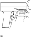
- FIG. 4 is a right side elevation view of the embodiment of the electronic device shown in FIGS. 1-3 joined to one possible deterrent device.
- FIG. 5 is a top view of the embodiment of electronic device shown in FIG. 1 without the rail positioner in place.
- FIG. 8 illustrates a finger resting against a finger engagement surface.
- FIG. 9 illustrates a finger resting against a ridge
- FIG. 10 illustrates a finger applying a force against a finger engagement surface to move a first engagement surface.
- FIG. 11 illustrates a finger applying a force against a finger engagement surface to move a second engagement surface.
- FIG. 12 illustrates a finger applying a force against a finger engagement surface to move both first engagement surface and second engagement surface into respective second positions.
- FIG. 13A illustrates an electronic device having contact members that rotate relative to a housing and with the contact members being in a first position.
- FIG. 13B illustrates the electronic device of FIG. 13A with a first contact member in a second position.
- FIG. 14A illustrates an electronic device having contact members that slide relative housing and with the contact members in a first position.
- FIG. 14B illustrates the electronic device of FIG. 14A with a first contact member in a second position.
- FIG. 14C illustrates the electronic device of FIG. 14A with a second contact member in a second position.
- FIG. 14D illustrates the electronic device of FIG. 14A with a first contact member and second contact member in their second positions.
- FIG. 15 shows another embodiment of an electronic device having an additional first contact member and an additional second contact member arranged to enable ambidextrous operation of the electronic device.
- FIG. 1 is a front, left, top isometric view of an electronic device 20 for use with a deterrent device 10 such as a firearm, dispersant, or other type of deterrent device.
- FIG. 2 and FIG. 3 respectively are top and side views of an optional rail positioner 40 .
- FIG. 4 is a right side elevation view of the embodiment of electronic device 20 joined to one possible deterrent device 10 .
- FIG. 5 is a top view of the embodiment of electronic device 20 shown in FIGS. 1-4 .
- electronic device 20 having a housing 22 with a first opening 24 allowing laser light to pass from inside housing 22 to the environment outside and a second opening 26 allowing an illuminating light to pass from inside of housing 22 to the environment outside.
- first opening 24 and second opening 26 may include windows (not shown) that protect against contaminants entering into housing 22 while allowing at least some light to pass through.
- windows may take the form of optical elements such as lenses prisms or other known forms of optical elements that allow light to pass through while also shaping redirecting focusing, filtering, coloring or diffusing such light.
- Housing 22 includes a rail mount 30 having opposing rail mounting surfaces 32 and 34 that are movable relative to each other. Clamping screws 36 and 38 cooperate with housing 22 to define an extent of maximum separation between rail mounting surfaces 32 and 34 . Clamping screws 36 and 38 can be loosened to increase separation between rail mounts 32 and 34 when positioning a rail 12 between rail mounting surfaces 32 and 34 . The separation between rail mounting surfaces 32 and 34 can then be decreased in order to clamp rail 12 between rail mounts 32 and 34 .
- Rail positioner 40 can be provided. Rail positioner 40 also can be positioned at any of a range of different positions between rail mounts 32 and 34 prior to assembly of electronic device 20 to deterrent device 10 .
- Rail positioner 40 is shown having a cross member 42 that is shaped to protrude upwardly into a recoil groove 15 that extends across a rail 12 to position housing 22 along a length of rail 12 .
- Rail positioner 40 can be fixed relative to rail mounts 34 by the vice-like action of closing the distance between rail mounts 32 and 34 .
- rail positioner 40 is illustrated with features 44 designed to engage co-designed features of rail mounting surfaces 32 and 34 to help ensure alignment and positioning of rail positioner 40 .
- Other mechanisms may also be used to fix a position of rail positioner 40 relative to housing 22 .
- first contact member 50 is movably associated with housing 22 .
- first contact member 50 can be mounted or otherwise mechanically linked to housing 22 in any other manner that enables some degree of movement between a first position and a second position relative to housing 22 .
- second contact member 60 is movably associated with housing 22 .
- second contact member 60 can be mounted or otherwise mechanically linked to housing 22 in any other manner that enables some degree of movement between a first position and a second position relative to housing 22 .
- first contact member 50 is arranged substantially above and generally aligned with second contact member 60 when first contact member 50 is in the first position and second contact member 60 is in the first position.
- FIG. 6 is a system view of the embodiment of electronic device 20 of FIG. 1 .
- contact members 50 and 60 extend partially within openings 54 and 64 of housing 22 for sliding movement between a first position and a second position.
- the first positions are defined by stops 51 and 61 which limit an extent to which first contact member 50 and second contact member 60 can extend from housing 22 .
- first contact member 50 , second contact member 60 , housing 22 or other components of electronic device 20 can be defined in other ways so that at least a portion of each of first contact member 50 and second contact member 60 is retained within housing 22 or otherwise mechanically associated with housing 22 .
- biasing member 70 applies a biasing force 90 that urges first contact member 50 away from an interior of housing 22 and into its first position.
- biasing member 80 applies a biasing force 100 that urges second contact member 60 away from an interior of housing 22 and into its first position.
- contact members 50 and 60 must be urged by forces greater than biasing forces 90 and 100 to cause contact members 50 and 60 to move from their respective first positions.
- FIG. 6 also illustrates a control system 110 in housing 22 .
- control system 110 has a controller 112 linked to a first input sensing circuit 120 and a second input sensing circuit 130 .
- First input sensing circuit 120 is adapted to sense when first contact member 50 is moved while second input sensing circuit 130 is adapted to sense when second contact member 60 is moved.
- Control system 110 may be adapted to cause a state of operation of electronic device 20 to change when a sensor 122 of first input sensing circuit 120 senses movement of first contact surface 50 .
- a laser system 144 can be activated when movement of first contact surface 50 is sensed.
- Control system 110 also may be adapted to cause a state of operation of electronic device 20 to change when a second sensor 132 of a second input sensing circuit 130 senses conditions indicating that second contact member 60 has been moved.
- a second sensor 132 of a second input sensing circuit 130 senses conditions indicating that second contact member 60 has been moved.
- an illumination system 146 having a light emitter 148 that can be activated or de-activated when movement of second contact member 60 is sensed.
- Control system 110 may also be adapted to select a third mode of operation when first sensing circuit 120 senses a change of state at first sensor 122 that is indicative of movement of first contact surface 50 and when second input sensing circuit 130 senses a change of state of second sensor 132 indicative of movement of second contact member 60 at about the same time, or within a predetermined time period or in any temporal or other pattern of movement indicative of intentional movement of both first contact surface 50 and second contact surface 60 .
- control system 110 may select a third mode of operation of electronic device 20 by activating or deactivating both laser system 144 and illumination system 146 when it is determined that first contact member 50 and second contact member 60 have been moved at the same time or within a predetermined time period or in any temporal or other pattern of movement indicative of intentional movement of both first contact surface 50 and second contact surface 60 .
- control system 110 may cause one or both of laser system 144 and illumination system 146 to enter into a special mode of operation when such conditions are detected such as where operation of both laser system 144 and illumination system 146 are operated in a particular manner that is different from the manner in which laser system 144 and illumination system 146 are operated when activated separately.
- control system 110 may have modes of operation intended to improve this outcome.
- laser system 144 and illumination system 146 may be operated in a non-continuous mode such as by being pulsed. Such pulsing can be at any of a variety of different frequencies such as between about 1 ⁇ 3 of a cycle per second to about 1,000,000 cycles per second.
- the current applied to and consequent light intensity generated by the laser system 144 or illumination system 146 may be adjusted between a system minimum and a system maximum for example to achieve desired levels of brightness, to extend battery life, to manage thermal output or laser efficiency.
- a light emitter 148 that generates particular wavelengths of light.
- the human eye has red, green and blue color sensors and interprets colors based upon the sensed combinations of these different colors of light.
- the human eye is not equally sensitive to all such colors.
- the color sensors in the human eye are more sensitive to green colors than to red and blue.
- green laser illuminators such as the ND-3 Laser Designator sold by BSA Optics, Fort Lauderdale, Fla., USA which generate a green illumination beam to illuminate a scene.
- the advantages of such illuminators include greater perceived illumination intensity per unit of energy consumed.
- green illuminators have long been associated with certain drawbacks.
- human visual acuity is not merely a function of sensing it is also a function of interpreting what is sensed and visual processing systems are not perfectly adapted to interpreting visual information in a single wavelength or narrow wavelength band of light as such light may interact with objects in a scene in ways that are not always intuitive to understand.
- objects may have surfaces with glare or absorption characteristics may appear differently when exposed to narrow bandwidth illumination than when exposed to broad bandwidth illumination.
- green illuminators can be complex, expensive, and require other engineering and design tradeoffs that may not be acceptable in applications.
- color information is another important characteristic used in interpreting visual information and color information itself may be distorted by narrow band illumination ways that are not fully appreciated by an observer.
- illumination system 146 may utilize a light emitter 148 that emits a light having a combination of wavelengths and intensities that are better matched both to human visual sensitivity and to visual processing.
- light emitter 148 emits a light having a high preponderance of a green light to take advantage of enhanced human light sensitivity in wavelengths that are perceived to be green by providing higher intensities of light in the green perceived wavelengths, while also providing at least enough light in wavelengths other than green to combine with the green light to create a “green-white” illumination of a scene.
- light emitter 148 includes a generally broad band emitter and a filter system that custom filters the broadband emitted light to achieve a precise wavelength combination.
- a combination of narrow band or single color emitters can be used in a combination that is calibrated or operated to secure a particular combination of wavelengths.
- Such an approach has the advantage of being customizable and precisely tunable by a user or manufacturer of the system to provide desired combinations of wavelengths. Additionally this approach allows for the selection of combinations of emitters having high efficiencies and other characteristics that may be desirable from weight, efficiency or manufacturability criteria.
- a third approach involves the use of single light emitters that are manufactured to efficiently emit light having the above described combination of wavelengths or an approximation thereof.
- the LUW CQAR (EQW) high-power LED sold by OSRAM Opto Semiconductors GmbH, Regensburg, Germany, emits light concentrated in the green perceived wavelengths, but having sufficient contributions from other wavelengths, create a white-green light of a type that provides the advantages described above.
- intensities of at least some of any illuminating light emitted at non-green wavelengths may be lower than those of the green light and lower than would be required to fully combine with the green light to create white light.
- an illuminator may be able to provide levels of perceived illumination of a scene comparable to those of a white or near white light emitter but with greater efficiency than such a white or near white light illuminator.
- operation of electronic device 20 requires that a user actuate a desired one or both of first contact member 50 and second contact member 60 and that the embodiments claimed and described herein enable a user can do so in an intuitive manner that requires little or no repositioning of an activating finger and that does not significantly distract a user from the management and control of the deterrent device 10 .
- a finger engagement surface 140 is formed in part by first contact member 50 and in part by second contact member 60 .
- Finger engagement surface 140 is shaped to receive a portion of a finger 200 positioned in part between first contact member 50 and second contact member 60 .
- finger engagement surface 140 may be shaped to guide a finger positioned against finger engagement surface 140 to a position that is within predetermined range of positions relative to first contact member 50 and second contact member 60 . This may be done by contouring or otherwise shaping first contact member 50 and second contact member 60 to form a finger engagement surface 140 that provides a receiving area for a finger.
- first contact member 50 defines a first finger receiving surface 150 extending generally from a first ridge 152 to a first contact member edge 154 of first contact member 50 adjacent to second contact member 60 .
- Finger receiving surface 150 defines a first part of finger engagement surface 140 .
- second contact member 60 defines a second finger receiving surface 160 extending generally from a second ridge 162 to a second contact member edge 164 of second contact member 60 .
- Second finger receiving surface 160 defines a remaining part of finger engagement surface 140 .
- first finger receiving surface 150 and second finger receiving surface 160 are generally illustrated as being symmetrically shaped but oppositely configured curved surfaces.
- First finger receiving surface 150 is shown extending from an optional ridge 152 to a first contact member edge 154 while second finger receiving surface 160 is shown extending from an optional ridge 162 to a second contact member edge 164 .
- other options are possible and within the spirit of what is described herein.
- FIGS. 7 and 8 illustrate respectively a right side cut away elevation view of a portion of electronic device 20 with a finger 200 and fingertip 202 shown in phantom and a system illustration of a portion of housing 22 , first contact member 50 and second contact member 60 with a finger 200 positioned against finger engagement surface 140 .
- finger 200 (shown in phantom in FIG. 1 ) is illustrated as a right hand index finger of a hand that is gripping or otherwise holding a deterrent device such as for example and without limitation, deterrent device 10 shown in FIG. 1 .
- electronic device 20 can be fixed to a rail 12 that is positioned between trigger guard 16 on a conventional pistol type deterrent device 10 and an end of a barrel 18 thereof.
- a user's right hand index finger can be positioned in an off of the trigger position and into finger engagement surface 140 .
- finger 200 may be positioned against finger engagement surface 140 in a manner that allows finger 200 to be repositioned onto trigger 14 after controlled activation of one or more of the systems of electronic device 20 if necessary.
- finger engagement surface 140 is shaped to receive finger 200 so as to help guide finger 200 into a range of positions well suited for pressing against one or both of first contact member 50 and second contact member 60 .
- finger engagement surface 140 is arranged to provide an area in which fingertip 202 can be pressed at a first level of force that does not overcome either of biasing forces 90 and 100 . This allows a finger 200 to rest against finger engagement surface 140 when a user is handling the deterrent device associated with electronic device 20 without changing a state of activation of electronic device 20 . This, in turn, allows finger 200 to be in a range of positions suited to either first contact member 50 or second contact member 60 , or both to be pressed quickly.
- Finger engagement surface 140 may be shaped to provide a user of electronic device 20 with some assistance in maintaining finger 200 in the range of positions suited for pressing against one or both of first contact member 50 and second contact member 60 when a portion of finger 200 such as fingertip 202 is positioned against or otherwise received by finger engagement surface 140 . This can be done as shown here by shaping finger engagement surface 140 in a manner that follows a general shape of a fingertip 202 , however in other embodiments, other shapes may be useful including but not limited to those that provide anti-slip, contaminant drainage or other contact or friction enhancing features.
- either of ridges 152 and 162 may provide a mechanical feature to help a user to hold fingertip 202 proximate to finger engagement surface 140 or to help prevent a finger 200 from unintentionally separating from finger engagement surface 140 such as during rapid movement of deterrent device 10 and electronic device 20 .
- Finger engagement surface 140 may include areas of significantly increased slope separating ridges 152 and 162 from finger engagement surface 140 . For example, a sharp increase in slope over a distance of about 0.5 mm more between finger engagement surface 140 and ridges 152 and 162 such as along ridge edges 156 and 166 may provide sufficient separation to allow ridges 152 and 162 to help mechanically maintain finger 200 from generally vertically shaking out of finger engagement surface 140 , when, for example the user is walking or running holding finger 200 against finger engagement surface 140 .
- ridges 152 and 162 can be shaped to provide additional tactile experience that readily identifies to the user of electronic device 20 that finger 200 or a portion thereof is positioned against ridge edges 156 or 166 . This can further help to alert a user that finger 200 is being urged out of finger engagement surface 140 .
- First ridge 152 and second ridge 162 can further be shaped to provide a tactile experience that is indicative of whether a finger is pressed against one of ridges 152 and 162 so as to alert a user that a fingertip 202 is not against finger engagement surface 140 .
- first ridge 152 provides a substantially different tactile experience at a fingertip 202 to a user who presses finger 200 against first ridge 152 than a user who presses fingertip 200 against finger engagement surface 140 .
- This different experience indicates that the user's index finger either has not been brought in to initial contact with finger engagement surface 140 or has left contact with finger engagement surface 140 .
- second ridge 162 provides a substantially different tactile experience against a user who presses finger 200 against second ridge 162 .
- first contact member 50 has a first ridge 152 with optional surface features 158 that are not found on second ridge 162 .
- Surface features 158 are designed so that a finger pressing against first ridge 152 as illustrated in FIG. 9 , will register a different tactile experience than a finger pressed against second ridge 162 .
- surface features 158 are illustrated as detents in first ridge 152 , however, in other embodiments other shapes can be used.
- second ridge 162 can have such features while first ridge 152 does not or both ridges 152 and 162 can have such surface features but with differences that are detectable.
- such surface features may extend into ridges edges such as first ridge edge 156 as shown or optionally section ridge 166 and optionally shown here such surface features may extend partially into a finger receiving area defined by finger engagement surface 140 such as may be provided by first finger receiving area surface 150 or second finger receiving surface 160 proximate to first ridge 156 or to second ridge 166 respectively.
- This arrangement also provides an opportunity for a user who wishes to move only one of first contact member 50 and second contact member 60 to determine on the basis of tactile feel that his or her finger is against first ridge 152 of first contact member 50 or second ridge 162 of second contact member 60 and to apply a force to move the desired contact member.
- surface features such as surface features 158 are shown taking the form of detents however, these can take other forms such as projections, or any other patterns of surface features that may be selected to create a predetermined tactile sensation in finger 200 when finger 200 is pressed against first ridge 152 or second ridge 162 . Additionally or optionally, features such as surface features 158 can be positioned on any portion of first contact member 50 and second contact member 60 outside of a finger receiving area proximate finger engagement surface 140 .
- FIGS. 10, 11 and 12 illustrate non-limiting embodiments of ways in which selections of modes of operation of electronic device 20 can be made using first contact member 50 and second contact member 60 .
- fingertip 202 may apply a first force 210 against a first portion 211 of finger engagement surface 140 in a manner that overcomes the urging of biasing force 90 and moves first contact member 50 to an extent that is sufficient to be detected by first input sensor 122 of first input sensing circuit 120 without substantially moving second contact member 60 .
- fingertip 202 alternatively may also apply a second force 212 against a second portion 213 of finger engagement surface 140 that is sufficient to overcome bias 100 and move that second contact member 60 in a manner that can be detected by second input sensor 132 of second input sensing circuit 130 without substantially moving first contact member 50 .
- a shape of finger engagement surface 140 , in first portion 211 and in second portion 213 can be adapted to help convert or translate forces 210 and 212 applied thereto into forces in that are applied in appropriate directions to overcome bias forces 90 and 100 .
- finger 200 and fingertip 202 may remain in generally the same place with generally the same orientation but apply first force 210 along one vector and second force 212 along a second, different, vector and as shown here against different portions of finger engagement surface 140 to move either first contact member 50 or second contact member 60 .
- a user also has a third option when finger 200 and fingertip 202 are positioned against finger engagement surface 140 in that finger 200 and fingertip 202 can apply a third force 214 against a third portion 215 of finger engagement surface to urge both of first contact member 50 and second contact member 60 to move in a manner that can be detected by first input sensing circuit 120 and second input sensing circuit 130 .
- the shape of finger engagement surface 140 in third portion 215 can be adapted to help capture, convert or redirect a third force applied thereto to forces along directions that enable detectable movement of both first contact member 50 and second contact member 60 .
- first contact member 50 may be mechanically associated with housing 22 so that movement of first contact member 50 from its first position to a second position separates or increases an extent of a separation of first contact member 50 from second contact member 60 . This can be done so as to reduce the risk that application of first force 210 will bring fingertip 202 into inadvertent contact with second contact member 60 to an extent that is sufficient to move second contact member 60 to its second position.
- first contact member 50 , second contact member 60 and housing 22 may cooperate so that first contact member 50 moves relative to housing 22 along a path that approximates a path of an expected vector of first force 210 and so that second contact member 60 moves relative to housing 22 along a path that that approximates an expected vector of force such as second force 212 .
- sensors 122 and 132 can take the form of mechanical switches that optionally incorporate biasing members 70 and 80 into a first position. This bias further urges contact members 50 and 60 , in a direction outward from the interior of housing 22 . Sensors 122 and 132 have an initial state when contact members 50 and 60 are biased in this manner. However, when a user applies force against contact members 50 and 60 that is sufficient to move one of contact members 50 and 60 a respective one of sensors 122 and 132 may be urged into a second state or otherwise generate signal indicative of the sensed movement.
- Sensors 122 and 132 can comprise any form of transducer or other device, material, or sensors capable of sensing movement created as the proximate result of force applied against contact members 50 and 60 and that can provide signals that can be used by controller 112 in a way that controller 112 or that can be used by any other portion of output such as an operating mode.
- Sensors 122 and 132 may take on other known mechanical, electrical, electro-mechanical, electro-optical and other forms of sensors including but not limited to piezoelectric sensors, Hall-effect or magnetic sensors, strain sensors, stress sensors, electrostatic sensors, pneumatic sensors, and optical sensors.
- any of contact members 50 and 60 move relative to housing 22 other than as necessary to enable reliable sensing thereof.
- any application of force causing any degree of movement of contact members 50 and 60 that can be sensed can be used.
- Such movement may constitute visible movement of or translation of contact members 50 and 60 or it may constitute generally imperceptible movement.
- such movement may be virtually imperceptible such as that which occasions an imperceptible movement such as that sufficient to create a detectable change in stress or strain within a contact members 50 and 60 .
- movement of contact members 50 and 60 may comprise movement made in response to changes in pressures, stress, or strain that cause slight or imperceptible movement.
- a portion of one of contact members 50 and 60 may move by change of shape, size or orientation or by otherwise reacting to compression, tension, torsion, shear, stress, strain and other known responses of materials, articles, or structures to applied forces.
- biasing members 70 and 80 may comprise contact members 50 and 60 such as where contact members 50 and 60 are formed from materials that resist forces applied by a finger of a user.
- any of contact members 50 and 60 may be formed from materials or structures that integrate functions of sensors 122 and 132 or components thereof.
- contact members 50 and 60 may be formed using a material that changes electro-magnetic properties or the interaction of the material an electromagnetic field when a force is applied thereto.
- materials that change resistance or that generate electricity when subject to stress or strain can be used to perform the functions of the respective one of the contact members 50 and 60 and one of sensors 122 and 132 if connected to control system 110 .
- finger engagement surface 140 can be shaped in shapes other than shown in FIGS. 1-12 .
- patterns of raised and lowered areas can be provided provide liquids or contaminants a path away from finger engagement surface 140 or to otherwise increase a grip or extent of contact with finger engagement surface 140 .
- portions of finger engagement surface 140 supplied by first contact member 50 and second contact member 60 be equally or generally equally distributed between first contact member 50 and first contact member 50 and second contact member 60 or to have generally symmetrical arrangements across a separation between contact members 50 and 60 .
- movement of contact members 50 and 60 may be in directions that do not involve changing an extent to which contact members 50 and 60 extend into or out of housing 22 .
- FIGS. 13A-13D illustrate an electronic device 20 having first contact member 50 arranged to pivot about a pivot point 220 or otherwise rotate from a first position proximate to first contact member 50 into a second position that is less proximate to second contact member 60 such as the position that is illustrated in FIG. 13B .
- second contact member 60 is arranged to pivot about a pivot point 222 or to otherwise rotate from a first position proximate to first contact member 50 into a second position that is less proximate to first contact member 50 such as the position that is illustrated in FIG. 13C .
- first contact member 50 and second contact member 60 may be biased into their respective first positions and finger engagement surface 140 can be defined so that application of force at a portion of finger engagement surface 140 which can for example be generally between first contact member 50 and second contact member 60 will drive both first contact member 50 and second contact member 60 to their second positions as is illustrated in FIG. 13D .
- FIGS. 14A-14D illustrate an electronic device 20 having a housing 22 and first contact member 50 that are configured so that, in response to application of a force such as force 240 , first contact member 50 can slide along a first slide path 230 or to otherwise move in a generally linear direction along housing 22 between a first position shown in FIG. 14A proximate to second contact member 60 into a second position that is less proximate to second contact member 60 such as the position that is illustrated in FIG. 14B .
- a force such as force 240
- second contact member 60 and housing 22 are configured so that, in response to a force such as force 242 , second contact member 60 can slide along a second slide path 232 or to otherwise move in a generally linear direction along housing 22 between a first position shown in FIG. 14A proximate to first contact member 50 into a second position that is less proximate to first contact member 50 such as the position as is illustrated in FIG. 14C .
- finger engagement surface 140 may be defined so that application of a force such as force 244 generally between first contact member 50 and second contact member 60 will drive both first contact member 50 and second contact member 60 to their second positions as is illustrated generally in FIG. 14D .
- FIG. 15 shows another embodiment of an electronic device 20 having an additional first contact member 52 and an additional second contact member 62 .
- additional contact members 52 and 62 extend partially within openings 56 and 66 of housing 22 for sliding movement between a first position and a second position.
- the first positions are defined by stops 53 and 63 which limit an extent to which additional first contact member 52 and additional second contact member 60 can extend from housing 22 .
- additional first contact member 52 , additional second contact member 62 , housing 22 or other components of electronic device 20 can be defined in other ways so that at least a portion of each of additional first contact member 52 and additional second contact member 62 is retained within housing 22 or otherwise mechanically associated with housing 22 and an additional finger engagement surface 190 is formed in part by additional first contact member 52 and in part by additional second contact member 62 .
- biasing member 72 applies a biasing force 92 that urges additional first contact member 52 away from an interior of housing 22 and into its first position.
- biasing member 82 applies a biasing force 102 that urges additional second contact member 60 away from an interior of housing 22 and into its first position.
- additional contact members 52 and 62 may be urged by forces greater than biasing forces 92 and 102 to cause additional contact members 52 and 62 to move from their respective first positions.
- Additional first contact member 52 and additional second contact member 62 have an additional first finger receiving surface 170 and an additional second finger receiving surface 180 that form, in combination an additional finger engagement surface 190 and optionally include ridges 172 and 182 .
- Such aspects of additional contact members 52 and 62 may have characteristics and be operable in manners that are similar to the characteristics and operations described above and that are otherwise consistent with the features and operations of first contact member 50 and second contact member 60 .
- a first sensing system 120 may include an additional first sensor 124 arranged to sense movement of additional first contact member 52 and second sensing system 130 includes an additional second sensor 134 arranged to sense movement of additional second contact member 62 .
- electronic device 20 may be arranged so that a single sensor such as first sensor 122 can detect movement of both first contact member 50 and additional first contact member 52 or so that second sensor 132 can detect movement of both second contact member 60 and additional second contact member 62 .
- a first sensor 122 can be positioned at a location where first sensor 122 can sense movement of first contact member 50 and additional first contact member 52 or a linkage can be positioned between first contact member 50 and additional first contact member 52 so that first contact member 50 and additional contact member 52 function together.
- a linkage can be used so that movement of either first contact member 50 or additional first contact member 52 can be sensed by a single first sensor 122 .
- Such a linkage can also be used with respect to second contact member 60 and additional second contact member 62 .
- first contact member 50 and second contact member 60 are positioned on opposite sides of housing 22 from additional first contact member 52 and additional second contact member 62 .
- Control system 110 may react to sensed movement of additional first contact member 52 and additional second contact member 62 in a manner similar to that described above when movement of first contact member 50 or second contact member 60 is sensed so as to provide ambidextrous operation of electronic device 20 .
- control system 110 may be adapted to cause an output of the electronic device 20 to change in a first manner when control system 110 senses conditions indicating that one of first contact member 50 or additional first contact member 52 has moved while also being to adapted to cause an output of the electronic device 20 to change in a second manner when control system 110 senses conditions indicating that one of the second contact member 60 or additional second contact member 62 has moved.
- control system 110 may be adapted to cause an output of electronic device 20 to change in a third manner when control system 110 senses conditions indicating that first contact member and the second contact member 60 have moved at about the same time or that the additional first contact member 52 and the additional second contact member 62 have moved at about the same time.
- control system 110 may react to sensed motion of additional first contact member 52 and additional second contact member 62 in different ways.
- additional contact members 52 and 62 can be used.
- additional contact members 52 and 62 may be arranged on a same surface of housing 22 as contact members 50 and 60 , or on other non-oppositional surfaces.
- first contact member 50 and second contact member 60 may operate with different types of motion or directions of actuation than additional first contact member 52 and additional second contact member 62 .
- first contact member 50 and second contact member 60 may operate as illustrated in the embodiment of FIGS. 13A-13D while additional first contact member 52 and additional second contact member 62 may operate as is illustrate in the embodiments of FIGS. 14A-14D .
- deterrent device 10 may take the form of a simulated deterrent device such as a weapon shaped training device, or devices that distribute paint or pepper balls, air soft munitions, pneumatic or other pressurized air projectile launching devices, optical beam emitters, and electromagnetic, fluidic and sonic emitters and models and simulators thereof.
- a simulated deterrent device such as a weapon shaped training device, or devices that distribute paint or pepper balls, air soft munitions, pneumatic or other pressurized air projectile launching devices, optical beam emitters, and electromagnetic, fluidic and sonic emitters and models and simulators thereof.
- a communication link 116 between first sensing system 120 and controller 112 and between second sensing system 130 and controller 112 may be made by way of a direct connection or by way of wireless signals sent from an optical, electrical or other signals transmitted between controller 112 and first sensing system 120 and signals transmitted between controller 112 and second sensing system 130 .
- wireless signals may be sent and received using for example and without limitation, active or passive radio frequency transponders incorporating or operatively associated with first sensing system 120 or second sensing system 130 .
- first sensor 122 and second sensor 132 may take the form of a sensor associated with a radio frequency transponder that polls
- transmitters and receivers using other forms of radio frequency, optical or other technology may be used including but not limited to those that conform to known wireless communication standards and specifications such as those promulgated by the ZigBee Alliance, Davis, Calif., USA, those promulgated by the Institute of Electrical and Electronics Engineers, New York, N.Y., USA, including but not limited to those promulgated under I.E.E.E. Standard 802.1 and those promulgated or maintained by the Bluetooth Special Interest Group, Kirkland Wash.
Landscapes
- Engineering & Computer Science (AREA)
- General Engineering & Computer Science (AREA)
- Physics & Mathematics (AREA)
- Optics & Photonics (AREA)
- Microelectronics & Electronic Packaging (AREA)
- Position Input By Displaying (AREA)
Abstract
Description
Claims (24)
Priority Applications (2)
| Application Number | Priority Date | Filing Date | Title |
|---|---|---|---|
| US16/102,119 US11473763B2 (en) | 2016-09-29 | 2018-08-13 | Electronic device for use with deterrent device |
| US17/967,769 US12320510B2 (en) | 2016-09-29 | 2022-10-17 | Electronic device for use with deterrent device |
Applications Claiming Priority (2)
| Application Number | Priority Date | Filing Date | Title |
|---|---|---|---|
| US15/279,841 US10047941B2 (en) | 2016-09-29 | 2016-09-29 | Electronic device for use with deterrent device |
| US16/102,119 US11473763B2 (en) | 2016-09-29 | 2018-08-13 | Electronic device for use with deterrent device |
Related Parent Applications (1)
| Application Number | Title | Priority Date | Filing Date |
|---|---|---|---|
| US15/279,841 Continuation US10047941B2 (en) | 2016-09-29 | 2016-09-29 | Electronic device for use with deterrent device |
Related Child Applications (1)
| Application Number | Title | Priority Date | Filing Date |
|---|---|---|---|
| US17/967,769 Continuation US12320510B2 (en) | 2016-09-29 | 2022-10-17 | Electronic device for use with deterrent device |
Publications (2)
| Publication Number | Publication Date |
|---|---|
| US20190041045A1 US20190041045A1 (en) | 2019-02-07 |
| US11473763B2 true US11473763B2 (en) | 2022-10-18 |
Family
ID=61687782
Family Applications (3)
| Application Number | Title | Priority Date | Filing Date |
|---|---|---|---|
| US15/279,841 Active US10047941B2 (en) | 2016-09-29 | 2016-09-29 | Electronic device for use with deterrent device |
| US16/102,119 Active 2038-01-24 US11473763B2 (en) | 2016-09-29 | 2018-08-13 | Electronic device for use with deterrent device |
| US17/967,769 Active 2037-01-09 US12320510B2 (en) | 2016-09-29 | 2022-10-17 | Electronic device for use with deterrent device |
Family Applications Before (1)
| Application Number | Title | Priority Date | Filing Date |
|---|---|---|---|
| US15/279,841 Active US10047941B2 (en) | 2016-09-29 | 2016-09-29 | Electronic device for use with deterrent device |
Family Applications After (1)
| Application Number | Title | Priority Date | Filing Date |
|---|---|---|---|
| US17/967,769 Active 2037-01-09 US12320510B2 (en) | 2016-09-29 | 2022-10-17 | Electronic device for use with deterrent device |
Country Status (1)
| Country | Link |
|---|---|
| US (3) | US10047941B2 (en) |
Cited By (2)
| Publication number | Priority date | Publication date | Assignee | Title |
|---|---|---|---|---|
| US20220140629A1 (en) * | 2019-12-16 | 2022-05-05 | Zhuhai Mefo Optical Instruments Co., Ltd. | Chargeable gunsight bracket and gunsight having the same |
| US20230184512A1 (en) * | 2016-09-29 | 2023-06-15 | Crosman Corporation | Electronic device for use with deterrent device |
Families Citing this family (15)
| Publication number | Priority date | Publication date | Assignee | Title |
|---|---|---|---|---|
| US10415932B1 (en) * | 2016-07-22 | 2019-09-17 | Knight Vision LLLP | Adjustable weapon-based mount for a monocular night-vision goggle |
| US10591250B2 (en) * | 2016-12-19 | 2020-03-17 | Crosman Corporation | Switchless sensing for electronic devices used with deterrent devices |
| US10557688B2 (en) * | 2018-01-26 | 2020-02-11 | La Police Gear, Inc. | Accessory mounting assembly for a firearm |
| USD851152S1 (en) * | 2018-03-14 | 2019-06-11 | Flir Surveillance, Inc. | Imaging device |
| WO2020014641A1 (en) * | 2018-07-12 | 2020-01-16 | Crosman Corporation | Deterrent-device accessory electromagnetic-radiation-based activation |
| USD907268S1 (en) * | 2019-07-23 | 2021-01-05 | Streamlight, Inc. | Mountable light |
| USD919149S1 (en) * | 2019-07-23 | 2021-05-11 | Streamlight, Inc. | Mountable light |
| US11506366B2 (en) * | 2020-08-07 | 2022-11-22 | Streamlight, Inc. | Mountable light having interchangeable clamping elements |
| USD1035813S1 (en) | 2020-09-02 | 2024-07-16 | Laser Aiming Systems Corporation | Laser finger stop |
| US12235075B1 (en) | 2020-09-02 | 2025-02-25 | Laser Aiming Systems Corporation | Firearm accessory device |
| USD947312S1 (en) * | 2021-04-28 | 2022-03-29 | Dongmei Li | Laser sight |
| USD1048527S1 (en) | 2022-01-14 | 2024-10-22 | Streamlight, Inc. | Cover for a light or similar article |
| USD1051198S1 (en) * | 2024-08-08 | 2024-11-12 | Shenzhen Yixin Information Technology Co., Ltd. | Night vision monocular |
| USD1083002S1 (en) * | 2025-01-17 | 2025-07-08 | Xinyi Jiang | Weapon light |
| USD1083003S1 (en) * | 2025-01-17 | 2025-07-08 | Jiayang Chu | Weapon light |
Citations (9)
| Publication number | Priority date | Publication date | Assignee | Title |
|---|---|---|---|---|
| US20050019079A1 (en) * | 2003-07-25 | 2005-01-27 | Griffin Jason T. | Staggered keyboard for a portable device |
| US20060052145A1 (en) * | 2004-09-09 | 2006-03-09 | Samsung Electronics Co., Ltd. | Data input key for a portable apparatus and key array thereof |
| US7264369B1 (en) * | 2004-08-17 | 2007-09-04 | Insight Technology, Inc. | Switch configuration for a tactical illuminator |
| US20070227056A1 (en) * | 2005-11-17 | 2007-10-04 | Howe Alan T | Tactical Illuminator |
| US20070277422A1 (en) * | 2006-05-31 | 2007-12-06 | Leapers, Inc. | Firearm target illumination implement |
| US20080014995A1 (en) * | 2006-03-30 | 2008-01-17 | Citizen Electronics Co., Ltd. | Mobile phone |
| US20170268849A1 (en) * | 2016-03-16 | 2017-09-21 | Bayco Products, Inc. | Coupled Dual Switch Actuators with Lockout Feature for a Lighting Attachment to a Firearm |
| US10047941B2 (en) * | 2016-09-29 | 2018-08-14 | Crosman Corporation | Electronic device for use with deterrent device |
| US20190301833A1 (en) * | 2015-11-16 | 2019-10-03 | Robert Marshall Campbell | Camera sight device for a weapon |
Family Cites Families (62)
| Publication number | Priority date | Publication date | Assignee | Title |
|---|---|---|---|---|
| US579416A (en) | 1897-03-23 | Faucet and filler for oil-cans | ||
| US541981A (en) | 1895-07-02 | Dumping-car-operating mechanism | ||
| USD506486S1 (en) | 2003-12-29 | 2005-06-21 | Digivogue Tech Co., Ltd. | Binocular |
| US7325352B2 (en) | 2004-04-06 | 2008-02-05 | Surefire, Llc | Accessory devices for firearms |
| US7591098B2 (en) | 2004-04-06 | 2009-09-22 | Surefire, Llc | Accessory devices for firearms |
| US7117624B2 (en) | 2004-04-06 | 2006-10-10 | Surefire, Llc | Accessory devices for firearms |
| US7334366B2 (en) | 2005-10-05 | 2008-02-26 | Surefire, Llc | Accessory mount for a firearm |
| US7240452B2 (en) | 2005-11-23 | 2007-07-10 | Shu-Li Ho | Structure for fixing a gun scope |
| USD547780S1 (en) | 2005-12-21 | 2007-07-31 | Leica Camera Ag | Monocular telescope with integrated laser range finder |
| TWD114318S1 (en) | 2006-01-23 | 2006-12-11 | 方礎光電科技股份有限公司 | Laser sight |
| USD586874S1 (en) | 2006-01-31 | 2009-02-17 | Insight Technology Incorporated | Weapon aiming device |
| US7421818B2 (en) | 2006-02-04 | 2008-09-09 | Lasermax, Inc. | Firearm mount with embedded laser sight |
| US8695267B2 (en) | 2006-02-04 | 2014-04-15 | Lasermax, Inc. | Firearm mount with embedded sight |
| USD568508S1 (en) | 2006-02-07 | 2008-05-06 | Insight Technology, Inc. | Tactical flashlight |
| USD570018S1 (en) | 2006-02-16 | 2008-05-27 | Insight Technology Incorporated | Flashlight |
| US8578647B2 (en) | 2007-01-12 | 2013-11-12 | American Defense Manufacturing, Llc | Locking quick release clamp assembly |
| US7926218B2 (en) | 2007-01-17 | 2011-04-19 | Surefire, Llc | Laser aiming apparatus using a rocker |
| US8109032B2 (en) | 2007-12-03 | 2012-02-07 | Sagi Faifer | Accessory holder with linear actuator |
| USD616956S1 (en) | 2009-01-08 | 2010-06-01 | Sheltered Wings, Inc. | Laser sight with push button interface |
| US20100229450A1 (en) | 2009-01-12 | 2010-09-16 | Novatac, Inc. | Quick release weapon mount and accessories for use therewith |
| USD612756S1 (en) | 2009-11-18 | 2010-03-30 | Insight Technology Incorporated | Laser |
| USD647159S1 (en) | 2009-12-21 | 2011-10-18 | Nikon Vision Co., Ltd. | Laser rangefinder |
| USD628323S1 (en) | 2010-01-14 | 2010-11-30 | Surefire, Llc | Lighting device |
| US8322066B2 (en) | 2010-01-18 | 2012-12-04 | Christopher Westra | Rail attachment mechanism |
| USD651628S1 (en) | 2010-01-21 | 2012-01-03 | Hangzhou Mission Infrared Electro Optocs Technology Co., Ltd. | Thermal infrared imager |
| US8567981B2 (en) | 2010-02-04 | 2013-10-29 | Elite Research, Llc | Laser aiming device integrated into an electro-optic battery source such as associated with a holographic sight |
| USD641826S1 (en) | 2010-04-07 | 2011-07-19 | Gs Development Ab | Sight without kick stop |
| US8915009B2 (en) | 2010-11-16 | 2014-12-23 | Crimson Trace Corporation | Modular sighting and lighting system for handguns |
| USD674858S1 (en) | 2010-12-02 | 2013-01-22 | Emissive Energy Corporation | Weapon mounted light |
| US8490313B2 (en) | 2011-01-18 | 2013-07-23 | Prototype Productions Incorporated Ventures Two, Llc | Apparatus for mounting accessories on the accessory rail of a weapon |
| US20120206799A1 (en) | 2011-02-11 | 2012-08-16 | Juan Carlos Casas | Binoculars with integrated laser designator/illuminator for illuminating an optical field of view |
| DE202011005580U1 (en) | 2011-04-25 | 2012-07-27 | Leica Camera Ag | Binocular telescope with integrated laser rangefinder |
| USD675281S1 (en) | 2011-06-21 | 2013-01-29 | Walter Speroni | Laser sight and mount |
| US8683731B2 (en) | 2011-09-26 | 2014-04-01 | Lasermax, Inc. | Firearm laser sight alignment assembly |
| USD679775S1 (en) | 2011-10-07 | 2013-04-09 | NcStar Inc. | Micro sighting device with built in laser |
| USD696377S1 (en) | 2012-01-03 | 2013-12-24 | Laser Devices, Inc. | Dual beam aiming laser |
| USD682977S1 (en) | 2012-01-10 | 2013-05-21 | Laser Devices, Inc. | Dual beam aiming laser |
| USD679304S1 (en) | 2012-03-06 | 2013-04-02 | Flir Systems, Inc. | Optical device |
| USD701279S1 (en) | 2012-09-25 | 2014-03-18 | Specialized Tactical Systems | Light with firearm mounting bracket |
| USD693867S1 (en) | 2012-11-01 | 2013-11-19 | Carl Zeiss Sports Optics Gmbh | Binocular |
| USD750685S1 (en) | 2012-12-03 | 2016-03-01 | Flir Systems, Inc. | Camera |
| USD704297S1 (en) | 2012-12-20 | 2014-05-06 | Ncstar, Inc. | Reflex sight with integrated laser sight and flashlight |
| US9062933B1 (en) * | 2013-01-07 | 2015-06-23 | John M. Allen | Tactical illuminator system |
| USD712001S1 (en) | 2013-03-11 | 2014-08-26 | Surefire, Llc | Lighting device |
| USD729339S1 (en) | 2013-10-22 | 2015-05-12 | Laser Devices, Inc. | Dual beam aiming laser |
| USD732134S1 (en) | 2014-01-09 | 2015-06-16 | Surefire, Llc | Lighting device |
| US9506721B2 (en) | 2014-02-24 | 2016-11-29 | N cSTAR, Inc. | Firearm mount with sight module |
| USD737399S1 (en) | 2014-03-16 | 2015-08-25 | NcSTAR. Inc. | Firearm mount with sighting module |
| USD738455S1 (en) | 2014-04-23 | 2015-09-08 | Crimson Trace Corporation | Laser device |
| USD746405S1 (en) | 2014-05-29 | 2015-12-29 | Laser Devices, Inc. | Dual beam aiming laser |
| USD752266S1 (en) | 2014-07-03 | 2016-03-22 | Lightforce Australia Pty Ltd. | Housing for light |
| USD749689S1 (en) | 2014-08-14 | 2016-02-16 | Ncstar, Inc. | Laser module for firearm |
| USD757886S1 (en) | 2014-09-25 | 2016-05-31 | Ncstar, Inc. | Sight module |
| US10871349B2 (en) * | 2015-01-05 | 2020-12-22 | Crosman Corporation | Firearm associated electronic device with acceleration resistant latch |
| USD762806S1 (en) | 2015-01-09 | 2016-08-02 | Laser Devices, Inc. | Single beam aiming laser |
| USD781983S1 (en) | 2015-01-16 | 2017-03-21 | Surefire, Llc | Lighting device |
| USD763399S1 (en) | 2015-01-19 | 2016-08-09 | Crimson Trace Corporation | Laser device |
| USD826363S1 (en) * | 2015-07-28 | 2018-08-21 | Crosman Corporation | Rail mounted light source |
| US10030939B2 (en) * | 2015-07-28 | 2018-07-24 | Crosman Corporation | Adjustable rail mounting system |
| USD779981S1 (en) | 2015-09-02 | 2017-02-28 | Nikon Vision Co., Ltd. | Laser range finder |
| USD830491S1 (en) * | 2016-09-29 | 2018-10-09 | Crosman Corporation | Electronic device for use with deterrent device |
| WO2020014641A1 (en) * | 2018-07-12 | 2020-01-16 | Crosman Corporation | Deterrent-device accessory electromagnetic-radiation-based activation |
-
2016
- 2016-09-29 US US15/279,841 patent/US10047941B2/en active Active
-
2018
- 2018-08-13 US US16/102,119 patent/US11473763B2/en active Active
-
2022
- 2022-10-17 US US17/967,769 patent/US12320510B2/en active Active
Patent Citations (9)
| Publication number | Priority date | Publication date | Assignee | Title |
|---|---|---|---|---|
| US20050019079A1 (en) * | 2003-07-25 | 2005-01-27 | Griffin Jason T. | Staggered keyboard for a portable device |
| US7264369B1 (en) * | 2004-08-17 | 2007-09-04 | Insight Technology, Inc. | Switch configuration for a tactical illuminator |
| US20060052145A1 (en) * | 2004-09-09 | 2006-03-09 | Samsung Electronics Co., Ltd. | Data input key for a portable apparatus and key array thereof |
| US20070227056A1 (en) * | 2005-11-17 | 2007-10-04 | Howe Alan T | Tactical Illuminator |
| US20080014995A1 (en) * | 2006-03-30 | 2008-01-17 | Citizen Electronics Co., Ltd. | Mobile phone |
| US20070277422A1 (en) * | 2006-05-31 | 2007-12-06 | Leapers, Inc. | Firearm target illumination implement |
| US20190301833A1 (en) * | 2015-11-16 | 2019-10-03 | Robert Marshall Campbell | Camera sight device for a weapon |
| US20170268849A1 (en) * | 2016-03-16 | 2017-09-21 | Bayco Products, Inc. | Coupled Dual Switch Actuators with Lockout Feature for a Lighting Attachment to a Firearm |
| US10047941B2 (en) * | 2016-09-29 | 2018-08-14 | Crosman Corporation | Electronic device for use with deterrent device |
Non-Patent Citations (1)
| Title |
|---|
| Notice of Allowance U.S. Appl. No. 16/102,119; AU2875 dated Apr. 10, 2018; Parent case of U.S. Appl. No. 16/102,119 (Year: 2018). * |
Cited By (4)
| Publication number | Priority date | Publication date | Assignee | Title |
|---|---|---|---|---|
| US20230184512A1 (en) * | 2016-09-29 | 2023-06-15 | Crosman Corporation | Electronic device for use with deterrent device |
| US12320510B2 (en) * | 2016-09-29 | 2025-06-03 | Crosman Corporation | Electronic device for use with deterrent device |
| US20220140629A1 (en) * | 2019-12-16 | 2022-05-05 | Zhuhai Mefo Optical Instruments Co., Ltd. | Chargeable gunsight bracket and gunsight having the same |
| US11658498B2 (en) * | 2019-12-16 | 2023-05-23 | Zhuhai Mefo Optical Instruments Co., Ltd. | Chargeable gunsight bracket and gunsight having the same |
Also Published As
| Publication number | Publication date |
|---|---|
| US20190041045A1 (en) | 2019-02-07 |
| US20230184512A1 (en) | 2023-06-15 |
| US10047941B2 (en) | 2018-08-14 |
| US20180087757A1 (en) | 2018-03-29 |
| US12320510B2 (en) | 2025-06-03 |
Similar Documents
| Publication | Publication Date | Title |
|---|---|---|
| US12320510B2 (en) | Electronic device for use with deterrent device | |
| US11473874B2 (en) | Weapon system with multi-function single-view scope | |
| US9316460B2 (en) | One hand operational combo sight device | |
| US20200200508A1 (en) | Pistol mounted multi-function flashlight | |
| US7315254B2 (en) | Proximity detector for night vision goggles shut-off | |
| AU2013248208B2 (en) | Combined laser range finder and sighting apparatus having dual function laser and method | |
| US7866083B2 (en) | Modular flashlight apparatus for firearm | |
| US7827726B2 (en) | Target illumination and sighting device with integrated non-lethal weaponry | |
| US5867313A (en) | Multipurpose night vision monocular | |
| US8485686B2 (en) | Multi-spectrum lighting device with plurality of switches and tactile feedback | |
| US8449131B2 (en) | Optical sight | |
| US10024527B2 (en) | Multi-spectrum lighting device with plural switches and tactile feedback | |
| US10386157B2 (en) | Illuminated sight system | |
| US20070173171A1 (en) | Reflected light controlled vehicle | |
| US20110261559A1 (en) | Flashlight with Tail Cap and Remote Switch | |
| US20210172705A1 (en) | Laser target pointer | |
| US10139179B2 (en) | Biometric identification system for gun | |
| KR20220147023A (en) | Cover system for laser accessory device | |
| US10578395B2 (en) | Grip activation system for firearm accessory | |
| US20240159500A1 (en) | Aiming device for firearm | |
| US20220187045A1 (en) | Detachable sight with momentary switch of light with control logic | |
| US20230016524A1 (en) | Counter measure effector with smart sight | |
| EP2426400A2 (en) | Elastic lamp with variable colors |
Legal Events
| Date | Code | Title | Description |
|---|---|---|---|
| FEPP | Fee payment procedure |
Free format text: ENTITY STATUS SET TO UNDISCOUNTED (ORIGINAL EVENT CODE: BIG.); ENTITY STATUS OF PATENT OWNER: LARGE ENTITY |
|
| AS | Assignment |
Owner name: CROSMAN CORPORATION, NEW YORK Free format text: ASSIGNMENT OF ASSIGNORS INTEREST;ASSIGNORS:MOCK, JEFFREY W.;KOWALCZYK, JOHN A., JR;REEL/FRAME:047090/0287 Effective date: 20180815 |
|
| AS | Assignment |
Owner name: COMPASS GROUP DIVERSIFIED HOLDINGS LLC, CONNECTICU Free format text: SUPPLEMENT NO. 1 TO INTELLECTUAL PROPERTY SECURITY AGREEMENT;ASSIGNOR:CROSMAN CORPORATION;REEL/FRAME:047332/0942 Effective date: 20181024 Owner name: COMPASS GROUP DIVERSIFIED HOLDINGS LLC, CONNECTICUT Free format text: SUPPLEMENT NO. 1 TO INTELLECTUAL PROPERTY SECURITY AGREEMENT;ASSIGNOR:CROSMAN CORPORATION;REEL/FRAME:047332/0942 Effective date: 20181024 |
|
| STPP | Information on status: patent application and granting procedure in general |
Free format text: DOCKETED NEW CASE - READY FOR EXAMINATION |
|
| STPP | Information on status: patent application and granting procedure in general |
Free format text: RESPONSE TO NON-FINAL OFFICE ACTION ENTERED AND FORWARDED TO EXAMINER |
|
| STPP | Information on status: patent application and granting procedure in general |
Free format text: NON FINAL ACTION MAILED |
|
| STPP | Information on status: patent application and granting procedure in general |
Free format text: RESPONSE TO NON-FINAL OFFICE ACTION ENTERED AND FORWARDED TO EXAMINER |
|
| STPP | Information on status: patent application and granting procedure in general |
Free format text: FINAL REJECTION MAILED |
|
| STPP | Information on status: patent application and granting procedure in general |
Free format text: DOCKETED NEW CASE - READY FOR EXAMINATION |
|
| STPP | Information on status: patent application and granting procedure in general |
Free format text: NON FINAL ACTION MAILED |
|
| STPP | Information on status: patent application and granting procedure in general |
Free format text: RESPONSE TO NON-FINAL OFFICE ACTION ENTERED AND FORWARDED TO EXAMINER |
|
| STPP | Information on status: patent application and granting procedure in general |
Free format text: FINAL REJECTION MAILED |
|
| STPP | Information on status: patent application and granting procedure in general |
Free format text: ADVISORY ACTION MAILED |
|
| STPP | Information on status: patent application and granting procedure in general |
Free format text: DOCKETED NEW CASE - READY FOR EXAMINATION |
|
| STPP | Information on status: patent application and granting procedure in general |
Free format text: NOTICE OF ALLOWANCE MAILED -- APPLICATION RECEIVED IN OFFICE OF PUBLICATIONS |
|
| STPP | Information on status: patent application and granting procedure in general |
Free format text: PUBLICATIONS -- ISSUE FEE PAYMENT RECEIVED |
|
| STPP | Information on status: patent application and granting procedure in general |
Free format text: PUBLICATIONS -- ISSUE FEE PAYMENT VERIFIED |
|
| STCF | Information on status: patent grant |
Free format text: PATENTED CASE |
|
| AS | Assignment |
Owner name: JPMORGAN CHASE BANK, N.A., AS COLLATERAL AGENT, ILLINOIS Free format text: SECURITY INTEREST;ASSIGNOR:CROSMAN CORPORATION;REEL/FRAME:067275/0210 Effective date: 20240430 |
|
| AS | Assignment |
Owner name: JPMORGAN CHASE BANK, N.A., AS COLLATERAL AGENT, ILLINOIS Free format text: SECURITY INTEREST;ASSIGNORS:DAISY MANUFACTURING COMPANY;CROSMAN CORPORATION;REEL/FRAME:067289/0588 Effective date: 20240430 |
|
| AS | Assignment |
Owner name: CROSMAN CORPORATION, NEW YORK Free format text: RELEASE BY SECURED PARTY;ASSIGNOR:COMPASS GROUP DIVERSIFIED HOLDINGS LLC;REEL/FRAME:067310/0011 Effective date: 20240430 |