US11400477B2 - Reversible nozzle in ultrasonic atomizer for clog prevention - Google Patents
Reversible nozzle in ultrasonic atomizer for clog prevention Download PDFInfo
- Publication number
- US11400477B2 US11400477B2 US16/211,320 US201816211320A US11400477B2 US 11400477 B2 US11400477 B2 US 11400477B2 US 201816211320 A US201816211320 A US 201816211320A US 11400477 B2 US11400477 B2 US 11400477B2
- Authority
- US
- United States
- Prior art keywords
- orientation
- nozzle
- plate
- connect fitting
- threads
- Prior art date
- Legal status (The legal status is an assumption and is not a legal conclusion. Google has not performed a legal analysis and makes no representation as to the accuracy of the status listed.)
- Active
Links
Images


Classifications
-
- B—PERFORMING OPERATIONS; TRANSPORTING
- B05—SPRAYING OR ATOMISING IN GENERAL; APPLYING FLUENT MATERIALS TO SURFACES, IN GENERAL
- B05D—PROCESSES FOR APPLYING FLUENT MATERIALS TO SURFACES, IN GENERAL
- B05D1/00—Processes for applying liquids or other fluent materials
- B05D1/02—Processes for applying liquids or other fluent materials performed by spraying
-
- B—PERFORMING OPERATIONS; TRANSPORTING
- B05—SPRAYING OR ATOMISING IN GENERAL; APPLYING FLUENT MATERIALS TO SURFACES, IN GENERAL
- B05B—SPRAYING APPARATUS; ATOMISING APPARATUS; NOZZLES
- B05B1/00—Nozzles, spray heads or other outlets, with or without auxiliary devices such as valves, heating means
- B05B1/26—Nozzles, spray heads or other outlets, with or without auxiliary devices such as valves, heating means with means for mechanically breaking-up or deflecting the jet after discharge, e.g. with fixed deflectors; Breaking-up the discharged liquid or other fluent material by impinging jets
- B05B1/262—Nozzles, spray heads or other outlets, with or without auxiliary devices such as valves, heating means with means for mechanically breaking-up or deflecting the jet after discharge, e.g. with fixed deflectors; Breaking-up the discharged liquid or other fluent material by impinging jets with fixed deflectors
-
- B—PERFORMING OPERATIONS; TRANSPORTING
- B05—SPRAYING OR ATOMISING IN GENERAL; APPLYING FLUENT MATERIALS TO SURFACES, IN GENERAL
- B05B—SPRAYING APPARATUS; ATOMISING APPARATUS; NOZZLES
- B05B12/00—Arrangements for controlling delivery; Arrangements for controlling the spray area
-
- B—PERFORMING OPERATIONS; TRANSPORTING
- B05—SPRAYING OR ATOMISING IN GENERAL; APPLYING FLUENT MATERIALS TO SURFACES, IN GENERAL
- B05B—SPRAYING APPARATUS; ATOMISING APPARATUS; NOZZLES
- B05B12/00—Arrangements for controlling delivery; Arrangements for controlling the spray area
- B05B12/02—Arrangements for controlling delivery; Arrangements for controlling the spray area for controlling time, or sequence, of delivery
- B05B12/04—Arrangements for controlling delivery; Arrangements for controlling the spray area for controlling time, or sequence, of delivery for sequential operation or multiple outlets
-
- B—PERFORMING OPERATIONS; TRANSPORTING
- B05—SPRAYING OR ATOMISING IN GENERAL; APPLYING FLUENT MATERIALS TO SURFACES, IN GENERAL
- B05B—SPRAYING APPARATUS; ATOMISING APPARATUS; NOZZLES
- B05B12/00—Arrangements for controlling delivery; Arrangements for controlling the spray area
- B05B12/14—Arrangements for controlling delivery; Arrangements for controlling the spray area for supplying a selected one of a plurality of liquids or other fluent materials or several in selected proportions to a spray apparatus, e.g. to a single spray outlet
-
- B—PERFORMING OPERATIONS; TRANSPORTING
- B05—SPRAYING OR ATOMISING IN GENERAL; APPLYING FLUENT MATERIALS TO SURFACES, IN GENERAL
- B05B—SPRAYING APPARATUS; ATOMISING APPARATUS; NOZZLES
- B05B12/00—Arrangements for controlling delivery; Arrangements for controlling the spray area
- B05B12/16—Arrangements for controlling delivery; Arrangements for controlling the spray area for controlling the spray area
- B05B12/18—Arrangements for controlling delivery; Arrangements for controlling the spray area for controlling the spray area using fluids, e.g. gas streams
-
- B—PERFORMING OPERATIONS; TRANSPORTING
- B05—SPRAYING OR ATOMISING IN GENERAL; APPLYING FLUENT MATERIALS TO SURFACES, IN GENERAL
- B05B—SPRAYING APPARATUS; ATOMISING APPARATUS; NOZZLES
- B05B12/00—Arrangements for controlling delivery; Arrangements for controlling the spray area
- B05B12/16—Arrangements for controlling delivery; Arrangements for controlling the spray area for controlling the spray area
- B05B12/32—Shielding elements, i.e. elements preventing overspray from reaching areas other than the object to be sprayed
- B05B12/36—Side shields, i.e. shields extending in a direction substantially parallel to the spray jet
-
- B—PERFORMING OPERATIONS; TRANSPORTING
- B05—SPRAYING OR ATOMISING IN GENERAL; APPLYING FLUENT MATERIALS TO SURFACES, IN GENERAL
- B05B—SPRAYING APPARATUS; ATOMISING APPARATUS; NOZZLES
- B05B13/00—Machines or plants for applying liquids or other fluent materials to surfaces of objects or other work by spraying, not covered by groups B05B1/00 - B05B11/00
- B05B13/002—Machines or plants for applying coating liquids or other fluent materials by inkjet
-
- B—PERFORMING OPERATIONS; TRANSPORTING
- B05—SPRAYING OR ATOMISING IN GENERAL; APPLYING FLUENT MATERIALS TO SURFACES, IN GENERAL
- B05B—SPRAYING APPARATUS; ATOMISING APPARATUS; NOZZLES
- B05B13/00—Machines or plants for applying liquids or other fluent materials to surfaces of objects or other work by spraying, not covered by groups B05B1/00 - B05B11/00
- B05B13/02—Means for supporting work; Arrangement or mounting of spray heads; Adaptation or arrangement of means for feeding work
- B05B13/04—Means for supporting work; Arrangement or mounting of spray heads; Adaptation or arrangement of means for feeding work the spray heads being moved during spraying operation
- B05B13/0405—Means for supporting work; Arrangement or mounting of spray heads; Adaptation or arrangement of means for feeding work the spray heads being moved during spraying operation with reciprocating or oscillating spray heads
-
- B—PERFORMING OPERATIONS; TRANSPORTING
- B05—SPRAYING OR ATOMISING IN GENERAL; APPLYING FLUENT MATERIALS TO SURFACES, IN GENERAL
- B05B—SPRAYING APPARATUS; ATOMISING APPARATUS; NOZZLES
- B05B13/00—Machines or plants for applying liquids or other fluent materials to surfaces of objects or other work by spraying, not covered by groups B05B1/00 - B05B11/00
- B05B13/02—Means for supporting work; Arrangement or mounting of spray heads; Adaptation or arrangement of means for feeding work
- B05B13/04—Means for supporting work; Arrangement or mounting of spray heads; Adaptation or arrangement of means for feeding work the spray heads being moved during spraying operation
- B05B13/0431—Means for supporting work; Arrangement or mounting of spray heads; Adaptation or arrangement of means for feeding work the spray heads being moved during spraying operation with spray heads moved by robots or articulated arms, e.g. for applying liquid or other fluent material to three-dimensional [3D] surfaces
- B05B13/0433—Means for supporting work; Arrangement or mounting of spray heads; Adaptation or arrangement of means for feeding work the spray heads being moved during spraying operation with spray heads moved by robots or articulated arms, e.g. for applying liquid or other fluent material to three-dimensional [3D] surfaces the work being vehicle components, e.g. vehicle bodies
-
- B—PERFORMING OPERATIONS; TRANSPORTING
- B05—SPRAYING OR ATOMISING IN GENERAL; APPLYING FLUENT MATERIALS TO SURFACES, IN GENERAL
- B05B—SPRAYING APPARATUS; ATOMISING APPARATUS; NOZZLES
- B05B13/00—Machines or plants for applying liquids or other fluent materials to surfaces of objects or other work by spraying, not covered by groups B05B1/00 - B05B11/00
- B05B13/02—Means for supporting work; Arrangement or mounting of spray heads; Adaptation or arrangement of means for feeding work
- B05B13/04—Means for supporting work; Arrangement or mounting of spray heads; Adaptation or arrangement of means for feeding work the spray heads being moved during spraying operation
- B05B13/0447—Installation or apparatus for applying liquid or other fluent material to conveyed separate articles
- B05B13/0452—Installation or apparatus for applying liquid or other fluent material to conveyed separate articles the objects being vehicle components, e.g. vehicle bodies
-
- B—PERFORMING OPERATIONS; TRANSPORTING
- B05—SPRAYING OR ATOMISING IN GENERAL; APPLYING FLUENT MATERIALS TO SURFACES, IN GENERAL
- B05B—SPRAYING APPARATUS; ATOMISING APPARATUS; NOZZLES
- B05B15/00—Details of spraying plant or spraying apparatus not otherwise provided for; Accessories
-
- B—PERFORMING OPERATIONS; TRANSPORTING
- B05—SPRAYING OR ATOMISING IN GENERAL; APPLYING FLUENT MATERIALS TO SURFACES, IN GENERAL
- B05B—SPRAYING APPARATUS; ATOMISING APPARATUS; NOZZLES
- B05B15/00—Details of spraying plant or spraying apparatus not otherwise provided for; Accessories
- B05B15/60—Arrangements for mounting, supporting or holding spraying apparatus
- B05B15/62—Arrangements for supporting spraying apparatus, e.g. suction cups
- B05B15/625—Arrangements for supporting spraying apparatus, e.g. suction cups designed to be placed on the ground
-
- B—PERFORMING OPERATIONS; TRANSPORTING
- B05—SPRAYING OR ATOMISING IN GENERAL; APPLYING FLUENT MATERIALS TO SURFACES, IN GENERAL
- B05B—SPRAYING APPARATUS; ATOMISING APPARATUS; NOZZLES
- B05B15/00—Details of spraying plant or spraying apparatus not otherwise provided for; Accessories
- B05B15/60—Arrangements for mounting, supporting or holding spraying apparatus
- B05B15/62—Arrangements for supporting spraying apparatus, e.g. suction cups
- B05B15/628—Arrangements for supporting spraying apparatus, e.g. suction cups of variable length
-
- B—PERFORMING OPERATIONS; TRANSPORTING
- B05—SPRAYING OR ATOMISING IN GENERAL; APPLYING FLUENT MATERIALS TO SURFACES, IN GENERAL
- B05B—SPRAYING APPARATUS; ATOMISING APPARATUS; NOZZLES
- B05B15/00—Details of spraying plant or spraying apparatus not otherwise provided for; Accessories
- B05B15/60—Arrangements for mounting, supporting or holding spraying apparatus
- B05B15/68—Arrangements for adjusting the position of spray heads
-
- B—PERFORMING OPERATIONS; TRANSPORTING
- B05—SPRAYING OR ATOMISING IN GENERAL; APPLYING FLUENT MATERIALS TO SURFACES, IN GENERAL
- B05B—SPRAYING APPARATUS; ATOMISING APPARATUS; NOZZLES
- B05B17/00—Apparatus for spraying or atomising liquids or other fluent materials, not covered by the preceding groups
- B05B17/04—Apparatus for spraying or atomising liquids or other fluent materials, not covered by the preceding groups operating with special methods
- B05B17/06—Apparatus for spraying or atomising liquids or other fluent materials, not covered by the preceding groups operating with special methods using ultrasonic or other kinds of vibrations
- B05B17/0607—Apparatus for spraying or atomising liquids or other fluent materials, not covered by the preceding groups operating with special methods using ultrasonic or other kinds of vibrations generated by electrical means, e.g. piezoelectric transducers
- B05B17/0623—Apparatus for spraying or atomising liquids or other fluent materials, not covered by the preceding groups operating with special methods using ultrasonic or other kinds of vibrations generated by electrical means, e.g. piezoelectric transducers coupled with a vibrating horn
- B05B17/063—Apparatus for spraying or atomising liquids or other fluent materials, not covered by the preceding groups operating with special methods using ultrasonic or other kinds of vibrations generated by electrical means, e.g. piezoelectric transducers coupled with a vibrating horn having an internal channel for supplying the liquid or other fluent material
-
- B—PERFORMING OPERATIONS; TRANSPORTING
- B05—SPRAYING OR ATOMISING IN GENERAL; APPLYING FLUENT MATERIALS TO SURFACES, IN GENERAL
- B05B—SPRAYING APPARATUS; ATOMISING APPARATUS; NOZZLES
- B05B17/00—Apparatus for spraying or atomising liquids or other fluent materials, not covered by the preceding groups
- B05B17/04—Apparatus for spraying or atomising liquids or other fluent materials, not covered by the preceding groups operating with special methods
- B05B17/06—Apparatus for spraying or atomising liquids or other fluent materials, not covered by the preceding groups operating with special methods using ultrasonic or other kinds of vibrations
- B05B17/0607—Apparatus for spraying or atomising liquids or other fluent materials, not covered by the preceding groups operating with special methods using ultrasonic or other kinds of vibrations generated by electrical means, e.g. piezoelectric transducers
- B05B17/0653—Details
- B05B17/0669—Excitation frequencies
-
- B—PERFORMING OPERATIONS; TRANSPORTING
- B05—SPRAYING OR ATOMISING IN GENERAL; APPLYING FLUENT MATERIALS TO SURFACES, IN GENERAL
- B05B—SPRAYING APPARATUS; ATOMISING APPARATUS; NOZZLES
- B05B3/00—Spraying or sprinkling apparatus with moving outlet elements or moving deflecting elements
- B05B3/02—Spraying or sprinkling apparatus with moving outlet elements or moving deflecting elements with rotating elements
-
- B—PERFORMING OPERATIONS; TRANSPORTING
- B05—SPRAYING OR ATOMISING IN GENERAL; APPLYING FLUENT MATERIALS TO SURFACES, IN GENERAL
- B05B—SPRAYING APPARATUS; ATOMISING APPARATUS; NOZZLES
- B05B3/00—Spraying or sprinkling apparatus with moving outlet elements or moving deflecting elements
- B05B3/14—Spraying or sprinkling apparatus with moving outlet elements or moving deflecting elements with oscillating elements; with intermittent operation
-
- B—PERFORMING OPERATIONS; TRANSPORTING
- B05—SPRAYING OR ATOMISING IN GENERAL; APPLYING FLUENT MATERIALS TO SURFACES, IN GENERAL
- B05B—SPRAYING APPARATUS; ATOMISING APPARATUS; NOZZLES
- B05B7/00—Spraying apparatus for discharge of liquids or other fluent materials from two or more sources, e.g. of liquid and air, of powder and gas
- B05B7/14—Spraying apparatus for discharge of liquids or other fluent materials from two or more sources, e.g. of liquid and air, of powder and gas designed for spraying particulate materials
- B05B7/1481—Spray pistols or apparatus for discharging particulate material
-
- B—PERFORMING OPERATIONS; TRANSPORTING
- B05—SPRAYING OR ATOMISING IN GENERAL; APPLYING FLUENT MATERIALS TO SURFACES, IN GENERAL
- B05D—PROCESSES FOR APPLYING FLUENT MATERIALS TO SURFACES, IN GENERAL
- B05D1/00—Processes for applying liquids or other fluent materials
- B05D1/02—Processes for applying liquids or other fluent materials performed by spraying
- B05D1/12—Applying particulate materials
-
- B—PERFORMING OPERATIONS; TRANSPORTING
- B05—SPRAYING OR ATOMISING IN GENERAL; APPLYING FLUENT MATERIALS TO SURFACES, IN GENERAL
- B05D—PROCESSES FOR APPLYING FLUENT MATERIALS TO SURFACES, IN GENERAL
- B05D3/00—Pretreatment of surfaces to which liquids or other fluent materials are to be applied; After-treatment of applied coatings, e.g. intermediate treating of an applied coating preparatory to subsequent applications of liquids or other fluent materials
- B05D3/06—Pretreatment of surfaces to which liquids or other fluent materials are to be applied; After-treatment of applied coatings, e.g. intermediate treating of an applied coating preparatory to subsequent applications of liquids or other fluent materials by exposure to radiation
- B05D3/061—Pretreatment of surfaces to which liquids or other fluent materials are to be applied; After-treatment of applied coatings, e.g. intermediate treating of an applied coating preparatory to subsequent applications of liquids or other fluent materials by exposure to radiation using U.V.
- B05D3/065—After-treatment
- B05D3/067—Curing or cross-linking the coating
-
- B—PERFORMING OPERATIONS; TRANSPORTING
- B25—HAND TOOLS; PORTABLE POWER-DRIVEN TOOLS; MANIPULATORS
- B25J—MANIPULATORS; CHAMBERS PROVIDED WITH MANIPULATION DEVICES
- B25J11/00—Manipulators not otherwise provided for
- B25J11/0075—Manipulators for painting or coating
-
- B—PERFORMING OPERATIONS; TRANSPORTING
- B05—SPRAYING OR ATOMISING IN GENERAL; APPLYING FLUENT MATERIALS TO SURFACES, IN GENERAL
- B05B—SPRAYING APPARATUS; ATOMISING APPARATUS; NOZZLES
- B05B17/00—Apparatus for spraying or atomising liquids or other fluent materials, not covered by the preceding groups
- B05B17/04—Apparatus for spraying or atomising liquids or other fluent materials, not covered by the preceding groups operating with special methods
- B05B17/06—Apparatus for spraying or atomising liquids or other fluent materials, not covered by the preceding groups operating with special methods using ultrasonic or other kinds of vibrations
- B05B17/0607—Apparatus for spraying or atomising liquids or other fluent materials, not covered by the preceding groups operating with special methods using ultrasonic or other kinds of vibrations generated by electrical means, e.g. piezoelectric transducers
- B05B17/0638—Apparatus for spraying or atomising liquids or other fluent materials, not covered by the preceding groups operating with special methods using ultrasonic or other kinds of vibrations generated by electrical means, e.g. piezoelectric transducers spray being produced by discharging the liquid or other fluent material through a plate comprising a plurality of orifices
- B05B17/0646—Vibrating plates, i.e. plates being directly subjected to the vibrations, e.g. having a piezoelectric transducer attached thereto
Definitions
- the present disclosure relates to high volume coating equipment and more specifically to an atomizer with a nozzle connector and a method of operating high volume coating equipment.
- Coating automotive vehicles e.g., vehicle frames, bodies, panels, etc.
- coatings e.g., primer, basecoat, clearcoat, etc.
- the overspray can be up to 40% of the coating that exits an applicator, or in other words, up to 40% of the coating that is purchased and applied is wasted (i.e. the transfer efficiency is ⁇ 60%).
- Equipment that captures overspray involves significant capital expenses when a paint shop is constructed, including large air handling systems to carry overspray down through a paint booth, construction of a continuous stream of water that flows under a floor of the paint booth to capture the overspray, filtration systems, and abatement, among others.
- costs to operate the equipment is high because air (flowing at greater than 200,000 cubic feet per minute) that flows through the paint booths must be conditioned, the flow of water must be maintained, compressed air must be supplied, and complex electrostatics are employed to improve transfer efficiency.
- the liquid coating is atomized by a nozzle that includes a rotating bell, which is essentially a rotating disk or bowl that spins at about 20,000-80,000 revolutions per minute.
- the liquid is typically ejected from an annular slot on a face of the rotating disk and is propelled towards the edges of the bell via centrifugal force.
- the liquid then forms ligaments and then droplets at the edges of the bell.
- this equipment works for its intended purpose, various issues arise as a result of its design.
- the momentum of the liquid coating is mostly lateral, meaning it is moving in a direction parallel to the vehicle rather than towards the vehicle.
- shaping air is applied that redirects the liquid droplets towards the vehicle.
- electrostatics are used to steer the droplets towards the vehicle.
- the droplets have a fairly wide size distribution, which can cause appearance issues.
- Ultrasonic atomization is an efficient means of producing droplets with a narrow size distribution with a droplet momentum perpendicular to the applicator surface (e.g., towards a surface of a vehicle).
- the small aperture size used for ultrasonic atomization can become clogged with debris or non-uniform or solid additives in the supplied liquid, such as metallic flakes mixed in a liquid basecoat of paint. Clogged apertures can cause uneven coating distribution and increased downtime to clean the nozzle.
- the present disclosure addresses these issues associated with traditional high-volume production paint booth operations.
- a nozzle for an atomizer includes a plate, a piezoelectric actuator, a body, and a connector.
- the plate defines an aperture.
- the actuator is configured to oscillate the plate.
- the body supports the plate.
- the connector is configured to reversibly mount the body to the atomizer in a first orientation and in a second orientation. In the first orientation, fluid exits the nozzle along a first axial direction through the aperture. In the second orientation, fluid exits the nozzle along an opposite axial direction through the aperture.
- the plate is disposed approximately midway between opposite axial ends of the body; the plate is symmetric along the first and second axial directions of the nozzle; the connector includes threads configured to engage mating threads on the atomizer; the actuator is configured to oscillate the plate in the first and second axial directions in response to an electric signal received by the actuator; the actuator is disposed about the plate; the actuator is integrally formed with the plate; the plate is one of a plurality of plates coupled to the body in an array, each plate defining at least one aperture; the plate defines a plurality of apertures; the connector is a quick-connect type connector; when the nozzle is in the first orientation the atomizer, the body, and a first side of the plate cooperate to define a reservoir, and wherein when the nozzle is in the second orientation the atomizer, the body, and an opposite side of the plate define the reservoir.
- an atomizer for applying a coating in another form, includes a base and a nozzle.
- the nozzle is configured to receive fluid from the base.
- the nozzle includes a connector configured to mate with the base in a first orientation and a second orientation. In the first orientation, the fluid exits the atomizer through an aperture of the nozzle along a first axial direction through the aperture. In the second orientation, fluid exits along an opposite axial direction through the aperture.
- the nozzle includes a body and a plate, the connector being coupled to the body, the plate being coupled to the body and defining the aperture, the plate being configured to oscillate the aperture relative to the body; the nozzle further includes a piezoelectric actuator configured to oscillate the plate relative to the body in response to an electric signal received by the actuator; the atomizer further includes a robotic arm, the base being mounted on the robotic arm for movement therewith; the atomizer includes a plurality of the nozzles coupled to the base.
- a method of applying a coating to a workpiece includes providing fluid from a base to a nozzle mounted on the base, oscillating a plate of the nozzle to cause the fluid to flow through an aperture in the plate along a first axial direction onto the workpiece, reversing an orientation of the plate relative to the base, and oscillating the plate so that fluid flows through the aperture along an opposite axial direction.
- the method further includes detecting a pressure of the fluid, determining that a blockage in the aperture is present based on a change in the pressure of the fluid, and reversing the orientation of the plate relative to the base in response to the blockage in the aperture being determined; the method further includes reversing the orientation of the plate relative to the base before providing a different fluid from the base to the nozzle; the method further includes reversing the orientation of the plate before coating a different workpiece.
- FIG. 1 is a planar view of an exemplary coating spray system according to the teachings of the present disclosure
- FIG. 2 schematically depicts a planar view of an applicator of the spray system of FIG. 1 , having an array of micro-applicators according to the teachings of the present disclosure
- FIG. 3 schematically depicts a portion of the applicator of FIG. 2 , illustrating one of the micro-applicators;
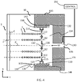
- FIG. 4 schematically depicts a side cross-sectional view of section 4 - 4 in FIG. 3 , illustrating a reversible nozzle according to the teachings of the present disclosure
- FIG. 5 schematically depicts a side cross-sectional view similar to FIG. 4 , illustrating a reversible nozzle of a second construction according to the teachings of the present disclosure
- FIG. 6 schematically depicts a side cross-sectional view of an applicator of a second construction having a reversible nozzle with an array of micro-applicators according to the teachings of the present disclosure
- FIG. 7 schematically depicts a flow chart for a method of operating a reversible nozzle applicator according to the teachings of the present disclosure.
- the present disclosure provides a variety of devices, methods, and systems for controlling the application of paint to automotive vehicles in a high production environment, which reduce overspray and increase transfer efficiency of the paint.
- automotive vehicles is merely exemplary and that other objects that are painted, such as industrial equipment and appliances, among others, may also be painted in accordance with the teachings of the present disclosure.
- the use of “paint” or “painting” should not be construed as limiting the present disclosure, and thus other materials such as coatings, primers, sealants, cleaning solvents, among others, are to be understood as falling within the scope of the present disclosure.
- the teachings of the present disclosure are based on a droplet spray generation device in which a perforate membrane is driven by a piezoelectric transducer.
- This device and variations thereof are described in U.S. Pat. Nos. 6,394,363, 7,550,897, 7,977,849, 8,317,299, 8,191,982, 9,156,049, 7,976,135, 9,452,442, and U.S. Published Application Nos. 2014/0110500, 2016/0228902, and 2016/0158789, which are incorporated herein by reference in their entirety.
- a material source 8 (e.g., a paint source) is included and includes at least one material M (materials M 1 , M 2 , M 3 , . . . M n shown in FIG. 1 ; also referred to herein simply as “material M”).
- the at least one material M includes different paint materials, different adhesive materials, different sealant materials, and the like.
- the arm 4 moves according to xyz coordinates with respect to rack 4 such that the material applicator 10 moves across a surface (not labeled) of the part P.
- a power source 6 is configured to supply power to arm 4 and rack 5 .
- Arm 4 and rack 5 are configured to supply material M from the material source 8 to the material applicator 10 such that a coating is applied to the surface of the part P.
- the material applicator 10 includes an array body 100 or nozzle with an applicator array 102 including a plurality of micro-applicators 110 or sub-nozzles.
- the array body 100 with the applicator array 102 is positioned on a base 140 .
- the base 140 is supported at the end of the articulating robotic arm 4 ( FIG. 1 ).
- the base 140 is supported by a spray bar (not shown) which can be stationary or can move in one, two, or three dimensions relative to a substrate S (shown in FIG. 4 ).
- Each of the micro-applicators 110 includes a plurality of apertures 112 through which a material M ( FIG. 4 ) is ejected such that atomized droplets 3 ( FIG. 4 ) of the material is provided.
- the material M ( FIG. 4 ) is generally a liquid material (e.g., primer, basecoat, clearcoat, etc.) but may optionally include interspersed solids, such as metallic flecks or other particles to provide a particular aesthetic look.
- the micro-applicators 110 can be arranged in any arrangement, such as a regular or an irregular pattern across the array body 100 .
- each of the micro-applicators 110 includes a nozzle body 116 , a micro-applicator plate 114 , and an actuator 120 .
- Each micro-applicator plate 114 defines a plurality of the apertures 112 extending through the micro-applicator plate 114 .
- the actuator 120 can be a transducer such as a piezoelectric material.
- the micro-applicator plate 114 is in mechanical communication with the actuator 120 such that activation of the actuator 120 (e.g., providing electrical power to the actuator 120 ) vibrates or oscillates the micro-applicator plate 114 as schematically depicted by the horizontal (z-direction) double-headed arrows in FIG. 4 .
- the array body 100 includes a material inlet 136 corresponding to each micro-applicator 110 .
- the array body 100 includes a back wall 131 and a cylindrical sidewall 132 such that a reservoir 134 for containing the material M is provided between the back wall 131 and the micro-applicator plate 114 .
- the back wall 131 , the sidewall 132 , a portion of the nozzle body 116 and the side of the micro-applicator plate 114 that faces the back wall 131 cooperate to define the reservoir 134 .
- the inlet 136 is in fluid communication with the reservoir 134 such that the material M flows through the inlet 136 and into the reservoir 134 .
- the actuator 120 is positioned between the micro-applicator plate 114 and the nozzle body 116 so that the nozzle body 116 supports the actuator 120 and the actuator 120 supports the micro-applicator plate 114 .
- the actuator 120 may be positioned between an outer edge surface 115 of the micro-applicator plate 114 and an inner surface 133 of the nozzle body 116 .
- the actuator 120 is an annular shape disposed about the micro-applicator plate 114 .
- the actuator 120 can be integrally formed with the micro-applicator plate 114 such that supplying power to the micro-applicator plate 114 oscillates the plate 114 .
- a control module 164 is in electric communication with the actuator 120 to provide power to and control operation of the actuator 120 .
- the material M is supplied to the reservoir 134 at a very low pressure or no pressure, such that surface tension of the material M resists the material M from flowing through the apertures 112 of the micro-applicator plate 114 unless the actuator 120 is activated and oscillates. That is, when the actuator 120 is activated and vibrates, the material M is ejected through and/or from the plurality of apertures 112 to provide a stream 5 of atomized droplets 3 .
- the stream 5 of atomized droplets 3 propagates generally parallel to a micro-applicator axis 2 ′ and forms a coating C on a surface s′ of the substrate S.
- the substrate S can be any suitable workpiece such as a vehicle part, frame, or body for example.
- the atomized droplets 3 have a narrow droplet size distribution (e.g., average droplet diameter).
- a particle or debris 138 such as solid debris or a large metal flake, is oriented so that it blocks one of the apertures 112 .
- the debris 138 can inhibit or prevent the material M from being ejected from that aperture 112 , which can cause the coating C to become less than optimally distributed.
- the nozzle body 116 further includes a connector.
- the nozzle body 116 is a cylindrical body and the connector includes external threads 142 disposed about the radially outer surface of the nozzle body 116 .
- the threads 142 are configured to mate with internal threads 146 disposed about the inner wall 132 of the array body 100 .
- the threads are configured such that the nozzle body 116 can be reversibly connected to the array body 100 . In other words, the nozzle body 116 can be screwed out of the array body 100 , turned around so that the opposite side of the micro-applicator plate 114 faces the back wall 131 , and then screwed back into the array body 100 .
- the threads 142 and mating threads 146 form a fluid-tight seal.
- a separate seal e.g., an o-ring, washer, face seal, etc.
- an o-ring, washer, face seal, etc. can be used to seal the nozzle body to the array body 100 .
- the nozzle body 116 includes a plurality of grip features configured to permit a tool (not shown) to easily grip and rotate the nozzle body 116 relative to the array body 100 .
- the grip features are rectangular recesses 150 that are diametrically opposite each other so that prongs of the tool (not shown) can be received within the recesses 150 to rotate the nozzle body 116 .
- the micro-applicator plate 114 is disposed axially midway between the opposite axial ends of the nozzle body 114 and the nozzle body 116 is axially symmetric about the plane defined by the micro-applicator plate 114 .
- the nozzle body 116 can be disconnected from the array body 100 , reversed, and then reconnected to the array body 100 . Then, the debris 138 is cleared from the aperture 112 by either activating the actuator 120 so that the material M pushes the debris 138 out, or by flushing the apertures 112 with a different fluid (e.g., air or a cleaning fluid) supplied from the inlet 136 .
- a different fluid e.g., air or a cleaning fluid
- FIG. 5 a cross-section of a material applicator 10 ′ of a second construction is illustrated.
- the material applicator 10 ′ is similar to the material applicator 10 ( FIGS. 1-4 ) except as otherwise shown or described herein.
- the material applicator 10 ′ includes a connector on the nozzle body 116 ′ that reversibly connects to a mating connector on the array body 100 ′, similar to the nozzle body 116 and array body 100 ( FIGS. 1-4 ), except that instead of mating threads, the connectors are a quick-connect type of connector.
- the nozzle body 116 ′ includes a male quick-connect fitting 510 and the array body 100 ′ includes a female quick-connect fitting 514 .
- the male quick-connect fitting 510 is reversible such that can mate with the female quick-connect fitting 514 in either axial direction.
- the array body 100 ′ includes a male quick-connect fitting and the nozzle body 116 ′ includes a reversible female quick-connect fitting.
- the male quick-connect fitting 510 includes a locking groove 518 , a first sealing surface 522 , and a second sealing surface 526 that extend circumferentially about the nozzle body 116 ′.
- the groove 518 is disposed axially between the two sealing surfaces 522 and 526 .
- the sealing surfaces 522 , 526 are configured to contact and seal with a mating sealing surface 530 disposed about an interior of the female quick-connect fitting 514 .
- the female quick-connect fitting 514 includes a plurality of locking balls 534 that are circumferentially spaced about the female quick-connect fitting 514 and configured to move radially between a locked position (shown) and an unlocked position.
- the balls 534 In the locked position, the balls 534 extend radially inward a greater extent than when in the unlocked position and can be captured within the groove 518 to engage a shoulder of the groove to prevent axial withdrawal of the male quick-connect fitting 510 .
- a collar 538 of the female quick-connect fitting 514 is movable in the axial direction to permit or prevent the balls from moving between the locked position and the unlocked position, depending on the axial position of the collar 538 . While one specific type of quick-connect fitting is illustrated, other types can be used.
- FIG. 6 a cross section of a material applicator 10 ′′ of a third construction is illustrated.
- the material applicator 10 ′′ is similar to the material applicator 10 ( FIG. 1-4 ) or 10 ′ ( FIG. 5 ) except as otherwise shown or described herein.
- Features denoted with double primed reference numerals are similar to the features shown and described in FIGS. 1-4 with similar, but non-primed reference numerals, or FIG. 5 with similar, but primed reference numerals, and only differences are described herein.
- the array body 100 ′′ includes a connector configured to reversibly connect to a mating connector on the base 140 ′′.
- the connector includes external threads 610 disposed about a radially outer surface of the array body 100 ′′ that are configured to mate with internal threads 614 on the base 140 ′′.
- the threads 610 , 614 are configured such that the array body 10 ′′ can be unscrewed from the base 140 ′′, turned around until the opposite side of the array body 100 ′′ faces the base 140 ′′, then screwed back into the base 140 ′′.
- the connectors can be other types of reversible connectors, such as a quick-connect similar to that shown in FIG. 5 .
- each micro-applicator 110 ′′ can receive material M from individual inlets (not shown).
- the micro-applicators 110 ′′ can be non-reversible relative to the array body 100 ′′, or can each be reversibly coupled to the array body 100 ′′ as shown and described above with reference to FIGS. 1-5 .
- a method 710 of operating an applicator to apply a coating to a substrate is illustrated in flow chart format.
- the method can be used with any of the applicators 10 , 10 ′, or 10 ′′ ( FIGS. 1-6 ) to keep debris from clogging the applicator.
- the coating material e.g., material M
- the nozzle of the applicator such as from the inlet 136 , 136 ′, or 136 ′′.
- the method 710 proceeds to step 718 , where power is provided to the nozzle's actuator(s) to oscillate the micro-applicator plate(s) and eject droplets of the material from the apertures of the micro-applicator plate(s) toward the substrate until a desired coating thickness is achieved.
- step 710 then proceeds to step 722 , where the orientation of one or more of the micro-applicator plates is reversed so that the flow of the material will be in the opposite direction through the apertures in the micro-applicator plate(s).
- the orientation of the micro-applicator plate is reversed in response to a blockage being detected.
- a blockage is determined to have occurred when a pressure changes within the reservoir or within the conduits upstream of the nozzle that supply the material to the nozzle.
- the pressure can be detected by a pressure sensor 160 , 160 ′, 160 ′′ (shown in FIGS. 4-6 ) and the pressure detected by the sensor 160 , 160 ′, 160 ′′ may increase as a result of one or more apertures of the micro-applicator plate being blocked.
- the sensor 160 , 160 ′, 160 ′′ is in communication with the control module 164 , 164 ′, 164 ′′ (shown in FIGS.
- control module 164 , 164 ′, 164 ′′ can move the applicator to automatically reverse the orientation of the micro-applicator plate without requiring input from an operator.
- the control module 164 , 164 ′, 164 ′′ can control the robotic arm 4 ( FIG. 1 ) and/or other corresponding tooling to automatically reverse the micro-applicator plate orientation.
- control module 164 , 164 ′, 164 ′′ can be configured to automatically reverse the nozzle orientation upon completion of a particular coating process.
- control module 164 , 164 ′, 164 ′′ can control the robotic arm 4 ( FIG. 1 ) and/or other corresponding tooling to automatically reverse the micro-applicator plate orientation when a different coating fluid material or a different coating color is needed, or upon completion of coating each vehicle.
- the control module can be configured to reverse the nozzle regardless of whether a blockage is detected in order to routinely clear any blockages.
- the micro-applicator plate can be reversed by either reversing the individual nozzle body or bodies as shown in FIGS. 4 and 5 , or by reversing the entire array body 100 ′′ as shown in FIG. 6 .
- the method 710 can optionally proceed to step 726 .
- the blockage is ejected from the micro-applicator plate by flushing the nozzle with air and/or a cleaning fluid before proceeding to step 730 .
- step 730 where fluid material (e.g., more of material M, or a different coating material such as a different color or a clear-coat) is provided to the nozzle.
- fluid material e.g., more of material M, or a different coating material such as a different color or a clear-coat
- step 734 power is provided to the actuator to oscillate the micro-applicator plate and spray the material toward the workpiece. If the nozzle has not been flushed after reversing the orientation, the blockage is still cleared when the actuator oscillates the micro-applicator plate since the fluid coating material will eject the blockage. Since the blockage can be cleared at step 734 without optional step 730 , omitting step 730 can save time and reduce the amounts of the materials used, since the supply lines do not need to be flushed to clear the blockage.
- the phrase at least one of A, B, and C should be construed to mean a logical (A OR B OR C), using a non-exclusive logical OR, and should not be construed to mean “at least one of A, at least one of B, and at least one of C.
Landscapes
- Engineering & Computer Science (AREA)
- Robotics (AREA)
- Physics & Mathematics (AREA)
- Plasma & Fusion (AREA)
- Mechanical Engineering (AREA)
- Application Of Or Painting With Fluid Materials (AREA)
- Nozzles (AREA)
- Spray Control Apparatus (AREA)
- Special Spraying Apparatus (AREA)
- Details Or Accessories Of Spraying Plant Or Apparatus (AREA)
- Coating Apparatus (AREA)
Abstract
Description
Claims (15)
Priority Applications (4)
| Application Number | Priority Date | Filing Date | Title |
|---|---|---|---|
| US16/211,320 US11400477B2 (en) | 2018-01-30 | 2018-12-06 | Reversible nozzle in ultrasonic atomizer for clog prevention |
| DE102019102239.8A DE102019102239A1 (en) | 2018-01-30 | 2019-01-29 | WENDEDÜSE IN ULTRASOUND TRANSDUCERS TO PREVENT CONDENSATION |
| CN201910092277.4A CN110090770A (en) | 2018-01-30 | 2019-01-30 | For preventing the turnable nozzle of blocking in ultrasonic atomizer |
| US17/847,372 US20220314263A1 (en) | 2018-01-30 | 2022-06-23 | Reversible nozzle in ultrasonic atomizer for clog prevention |
Applications Claiming Priority (2)
| Application Number | Priority Date | Filing Date | Title |
|---|---|---|---|
| US201862624013P | 2018-01-30 | 2018-01-30 | |
| US16/211,320 US11400477B2 (en) | 2018-01-30 | 2018-12-06 | Reversible nozzle in ultrasonic atomizer for clog prevention |
Related Child Applications (1)
| Application Number | Title | Priority Date | Filing Date |
|---|---|---|---|
| US17/847,372 Division US20220314263A1 (en) | 2018-01-30 | 2022-06-23 | Reversible nozzle in ultrasonic atomizer for clog prevention |
Publications (2)
| Publication Number | Publication Date |
|---|---|
| US20190232320A1 US20190232320A1 (en) | 2019-08-01 |
| US11400477B2 true US11400477B2 (en) | 2022-08-02 |
Family
ID=67391243
Family Applications (9)
| Application Number | Title | Priority Date | Filing Date |
|---|---|---|---|
| US16/211,320 Active US11400477B2 (en) | 2018-01-30 | 2018-12-06 | Reversible nozzle in ultrasonic atomizer for clog prevention |
| US16/211,324 Active 2039-03-17 US11364516B2 (en) | 2018-01-30 | 2018-12-06 | Ultrasonic atomizer with acoustic focusing device |
| US16/211,554 Active US10940501B2 (en) | 2018-01-30 | 2018-12-06 | Composite ultrasonic material applicators with individually addressable micro-applicators and methods of use thereof |
| US16/211,334 Active US10799905B2 (en) | 2018-01-30 | 2018-12-06 | Ultrasonic material applicators and methods of use thereof |
| US16/211,316 Active US10864541B2 (en) | 2018-01-30 | 2018-12-06 | Ultrasonic atomizer with quick-connect mechanism |
| US16/211,547 Active US10792693B2 (en) | 2018-01-30 | 2018-12-06 | Ultrasonic applicators with UV light sources and methods of use thereof |
| US17/020,381 Abandoned US20200406286A1 (en) | 2018-01-30 | 2020-09-14 | Ultrasonic applicators with uv light sources and methods of use thereof |
| US17/069,260 Active 2040-09-18 US12162030B2 (en) | 2018-01-30 | 2020-10-13 | Ultrasonic material applicators and methods of use thereof |
| US17/155,776 Active 2039-11-06 US12005463B2 (en) | 2018-01-30 | 2021-01-22 | Composite ultrasonic material applicators with individually addressable micro-applicators and methods of use thereof |
Family Applications After (8)
| Application Number | Title | Priority Date | Filing Date |
|---|---|---|---|
| US16/211,324 Active 2039-03-17 US11364516B2 (en) | 2018-01-30 | 2018-12-06 | Ultrasonic atomizer with acoustic focusing device |
| US16/211,554 Active US10940501B2 (en) | 2018-01-30 | 2018-12-06 | Composite ultrasonic material applicators with individually addressable micro-applicators and methods of use thereof |
| US16/211,334 Active US10799905B2 (en) | 2018-01-30 | 2018-12-06 | Ultrasonic material applicators and methods of use thereof |
| US16/211,316 Active US10864541B2 (en) | 2018-01-30 | 2018-12-06 | Ultrasonic atomizer with quick-connect mechanism |
| US16/211,547 Active US10792693B2 (en) | 2018-01-30 | 2018-12-06 | Ultrasonic applicators with UV light sources and methods of use thereof |
| US17/020,381 Abandoned US20200406286A1 (en) | 2018-01-30 | 2020-09-14 | Ultrasonic applicators with uv light sources and methods of use thereof |
| US17/069,260 Active 2040-09-18 US12162030B2 (en) | 2018-01-30 | 2020-10-13 | Ultrasonic material applicators and methods of use thereof |
| US17/155,776 Active 2039-11-06 US12005463B2 (en) | 2018-01-30 | 2021-01-22 | Composite ultrasonic material applicators with individually addressable micro-applicators and methods of use thereof |
Country Status (3)
| Country | Link |
|---|---|
| US (9) | US11400477B2 (en) |
| CN (6) | CN110090744A (en) |
| DE (1) | DE102019102240A1 (en) |
Families Citing this family (20)
| Publication number | Priority date | Publication date | Assignee | Title |
|---|---|---|---|---|
| US11413643B2 (en) * | 2018-01-30 | 2022-08-16 | Ford Motor Company | Composite ultrasonic material applicators with embedded shaping gas micro-applicators and methods of use thereof |
| US11400477B2 (en) * | 2018-01-30 | 2022-08-02 | Ford Motor Company | Reversible nozzle in ultrasonic atomizer for clog prevention |
| DE102019102232A1 (en) * | 2018-01-30 | 2019-08-01 | Ford Motor Company | ULTRASONIC TRANSMITTER WITH ACOUSTIC FOCUSING DEVICE |
| CN110653077B (en) * | 2019-10-09 | 2021-04-09 | 湖南大用环保科技有限公司 | Self-cleaning anti-blocking nozzle |
| CN110882874B (en) * | 2019-11-11 | 2025-02-11 | 北京东方金荣超声电器有限公司 | Bidirectional reflection ultrasonic atomization transducer |
| US12280554B2 (en) * | 2019-11-21 | 2025-04-22 | Divergent Technologies, Inc. | Fixtureless robotic assembly |
| DE102020204132A1 (en) * | 2020-03-30 | 2021-09-30 | Robert Bosch Gesellschaft mit beschränkter Haftung | Media output device and method of operating a media output device |
| FR3115716B1 (en) * | 2020-11-05 | 2023-12-22 | Exel Ind | METHOD AND INSTALLATION FOR APPLYING A COATING PRODUCT TO A SURFACE |
| US12083556B2 (en) * | 2020-12-21 | 2024-09-10 | Nissan North America, Inc. | Acoustic force assisted painting system |
| US12420296B2 (en) * | 2021-10-06 | 2025-09-23 | Ford Motor Company | Ultrasonic atomizer for applying a coating to a substrate with electrostatic charge to prevent droplet coalescence during atomization |
| DE102022100401A1 (en) | 2022-01-10 | 2023-07-13 | Dürr Systems Ag | Application system and associated monitoring procedure |
| WO2023147390A2 (en) | 2022-01-25 | 2023-08-03 | Divergent Technologies, Inc. | Measurement-based corrections for structure assembly |
| CN114602275B (en) * | 2022-04-26 | 2022-08-19 | 常春光 | Dust device is used in road surface management of adjustable watering scope |
| USD989815S1 (en) * | 2022-07-28 | 2023-06-20 | Leotech S.R.L. | Mobile pump for liquids |
| IT202200021720A1 (en) * | 2022-10-21 | 2024-04-21 | Dental Four Srl | APPARATUS AND METHOD FOR MANUFACTURING DENTAL PROSTHESES |
| CN116116627B (en) * | 2023-02-20 | 2025-10-17 | 福安市欧泉电机有限公司 | Centrifugal pump production equipment |
| JP7392192B1 (en) * | 2023-04-28 | 2023-12-05 | アーベーベー・シュバイツ・アーゲー | Painting machine |
| US20250303441A1 (en) * | 2024-03-26 | 2025-10-02 | Ford Global Technologies, Llc | Vision-controlled precision paint touch-up system and method |
| DE102024117798A1 (en) * | 2024-06-25 | 2026-01-08 | Dürr Systems Ag | Coating process and associated coating system |
| CN223807691U (en) * | 2025-03-06 | 2026-01-16 | 佘建生 | toy water gun |
Citations (58)
| Publication number | Priority date | Publication date | Assignee | Title |
|---|---|---|---|---|
| US4038570A (en) | 1974-03-20 | 1977-07-26 | Durley Iii Benton A | Ultrasonic piezoelectric transducer drive circuit |
| US4583694A (en) * | 1984-06-08 | 1986-04-22 | Nordson Corporation | Spray nozzle and removal tool |
| GB2215240A (en) | 1988-02-25 | 1989-09-20 | Ford Motor Co | Paint spraying apparatus |
| JPH0538809A (en) | 1991-08-07 | 1993-02-19 | Seiko Epson Corp | Ink jet head |
| US5387444A (en) | 1992-02-27 | 1995-02-07 | Dymax Corporation | Ultrasonic method for coating workpieces, preferably using two-part compositions |
| US5516043A (en) | 1994-06-30 | 1996-05-14 | Misonix Inc. | Ultrasonic atomizing device |
| US5540384A (en) | 1990-01-25 | 1996-07-30 | Ultrasonic Systems, Inc. | Ultrasonic spray coating system |
| JPH08215616A (en) | 1995-02-10 | 1996-08-27 | Akimichi Koide | Ultrasonic applicator |
| US5624075A (en) | 1994-05-09 | 1997-04-29 | Itw Oberflachentechnik Gmbh | Spray apparatus attachment device |
| US5636798A (en) | 1994-05-26 | 1997-06-10 | Gema Volstatic Ag | Electrostatic spray device |
| US5669971A (en) | 1994-04-06 | 1997-09-23 | Specialty Coating Systems, Inc. | Selective coating apparatus |
| DE19631811C1 (en) | 1996-08-07 | 1998-02-26 | Basf Lacke & Farben | Apparatus measuring spreading characteristics of sprayed materials e.g. varnishes, paints |
| US5823428A (en) | 1994-06-23 | 1998-10-20 | The Technology Partnership Plc | Liquid spray apparatus and method |
| US6206301B1 (en) * | 1999-07-15 | 2001-03-27 | Phillip E. Pruett | Reversible spray nozzle |
| US6394363B1 (en) | 1998-04-17 | 2002-05-28 | The Technology Partnership Plc | Liquid projection apparatus |
| JP2003091010A (en) | 2001-09-18 | 2003-03-28 | Seiko Epson Corp | Method for forming spacer for liquid crystal gap and apparatus for discharging microdroplets used in the method |
| US6666835B2 (en) | 1999-05-14 | 2003-12-23 | University Of Washington | Self-cooled ultrasonic applicator for medical applications |
| US6755985B2 (en) | 2000-04-19 | 2004-06-29 | Ford Global Technologies, Llc | Silicon-doped amorphous carbon coating for paint bell atomizers |
| US6896193B2 (en) * | 2002-11-26 | 2005-05-24 | S.C. Johnson & Son, Inc. | Atomizer with improved wire type atomizing element support and method of making same |
| US20060005766A1 (en) | 2002-11-12 | 2006-01-12 | Abb Patent Gmbh | Ultrasonic standing wave spraying arangement |
| DE20023848U1 (en) | 2000-10-30 | 2006-12-28 | Voxeljet Technology Gmbh | Device for applying atomized fluids, e.g. for rapid prototyping, has ultrasonic atomizers supplied with fluid essentially arranged above defined region to which atomized fluid is to be applied, at least one is movable over defined region |
| US7168633B2 (en) | 2005-04-12 | 2007-01-30 | Industrial Technology Research Institute | Spraying device |
| US20070051827A1 (en) * | 2005-09-08 | 2007-03-08 | Sheng-Chih Shen | Spraying device |
| US20070102537A1 (en) | 2003-06-18 | 2007-05-10 | Abb Patent Gmbh | Ultrasonic standing-wave atomizer arrangement |
| EP1884365A1 (en) | 2006-07-28 | 2008-02-06 | Abb Research Ltd. | Paint applicator and coating method |
| US7350890B2 (en) | 2004-08-26 | 2008-04-01 | The Boeing Company | Apparatus and methods for applying images to a surface |
| US7550897B2 (en) | 2004-04-07 | 2009-06-23 | The Technology Partnership Plc | Electronic drive system for a droplet spray generation device |
| US7704564B2 (en) | 2005-07-28 | 2010-04-27 | Garmat Usa Inc. | UV curing structure and process |
| US20100183820A1 (en) | 2009-01-16 | 2010-07-22 | Ford Global Technologies, Llc | Methods for curing uv-curable coatings |
| US20100285234A1 (en) | 2006-06-22 | 2010-11-11 | Ciba Corporation | Actinic radiation-curable coating composition |
| US7934665B2 (en) | 2003-03-28 | 2011-05-03 | Ultrasonic Systems Inc. | Ultrasonic spray coating system |
| US7976135B2 (en) | 2006-10-12 | 2011-07-12 | The Technology Partnership Plc | Liquid projection apparatus |
| US7977849B2 (en) | 2007-03-19 | 2011-07-12 | The Technology Partnership Plc | Droplet spray generation device |
| US8016209B2 (en) * | 2004-06-09 | 2011-09-13 | Ep Systems Sa | Liquid droplet plug and spray system |
| US8191982B2 (en) | 2006-10-12 | 2012-06-05 | The Technology Partnership Plc | Liquid projection apparatus |
| US8317299B2 (en) | 2006-10-12 | 2012-11-27 | The Technology Partnership Plc | Liquid projection apparatus |
| US20130079732A1 (en) * | 2009-11-18 | 2013-03-28 | Reckitt Benckiser Llc | Ultrasonic Surface Treatment Device and Method |
| US8440014B2 (en) | 2007-04-27 | 2013-05-14 | Nippon Sheet Glass Company, Limited | Bright pigment, and bright coating composition and automotive body coating each containing the same |
| DE102011088373A1 (en) | 2011-12-13 | 2013-06-13 | Robert Bosch Gmbh | Hand color dispenser for use in hand color gun, has color delivery unit applying colorant on workpiece in operating mode, and computing unit changing color delivery of color delivery unit in operating mode |
| US8524330B2 (en) | 2009-03-06 | 2013-09-03 | GM Global Technology Operations LLC | Method and apparatus for paint curing |
| CN103736620A (en) | 2014-01-20 | 2014-04-23 | 佛山市中国科学院上海硅酸盐研究所陶瓷研发中心 | Preparation method for ultrasonic atomization spraying film |
| US20140110500A1 (en) | 2011-05-16 | 2014-04-24 | The Technology Partnership Plc. | Separable membrane improvements |
| US8821802B2 (en) | 2009-01-08 | 2014-09-02 | Scentcom Ltd. | Method and apparatus for computer controlled scent delivery |
| DE102013205171A1 (en) | 2013-03-22 | 2014-09-25 | Krautzberger Gmbh | Spraying system, spraying device, quick-change adapter and changing device, coating system and method for coating |
| CN104689946A (en) | 2014-07-30 | 2015-06-10 | 北京东方金荣超声电器有限公司 | Superfine ultrasonic sprayer |
| CN104841592A (en) | 2015-04-09 | 2015-08-19 | 徐州德坤电气科技有限公司 | Intelligent automatic spraying unit based on digital bus and usage method thereof |
| US9149750B2 (en) | 2006-09-29 | 2015-10-06 | Mott Corporation | Sinter bonded porous metallic coatings |
| US9156049B2 (en) | 2010-03-25 | 2015-10-13 | The Technology Partnership, Plc. | Liquid projection apparatus |
| US20160059262A1 (en) | 2014-08-29 | 2016-03-03 | Carmax Business Services, Llc | Devices, systems, and methods for curing a coating |
| US20160158789A1 (en) | 2013-07-09 | 2016-06-09 | The Technology Partnership Plc | Separable membrane improvements |
| US20160228902A1 (en) | 2013-09-13 | 2016-08-11 | The Technology Partnership Plc | Fluid management for vibrating perforate membrane spray systems |
| US9452442B2 (en) | 2010-08-11 | 2016-09-27 | The Technology Partnership Plc | Electronic spray device improvements |
| US20160310982A1 (en) * | 2013-12-19 | 2016-10-27 | Koninklijke Philips N.V. | An assembly for use in a liquid droplet apparatus |
| US9592524B2 (en) | 2010-05-06 | 2017-03-14 | Duerr Systems Gmbh | Coating device comprising a jet of coating medium which is broken down into drops |
| US20170225186A1 (en) * | 2016-02-04 | 2017-08-10 | Rain Deck, LLC | Energized fluid nozzles for splash pads |
| WO2018108572A1 (en) | 2016-12-14 | 2018-06-21 | Dürr Systems Ag | Print head with a displacing and/or rotating mechanism for at least one nozzle row |
| KR20180080977A (en) | 2017-01-05 | 2018-07-13 | 두림야스카와(주) | Paint spraying apparatus with easy attachment and detachment of paint spraying nozzle |
| WO2018162872A1 (en) | 2017-03-07 | 2018-09-13 | Technijet Digital Limited | Apparatus and method for spray treating fabric |
Family Cites Families (76)
| Publication number | Priority date | Publication date | Assignee | Title |
|---|---|---|---|---|
| US2564431A (en) * | 1947-09-24 | 1951-08-14 | Greenspoon Hyman | Clearing means for nozzles |
| US3679132A (en) * | 1970-01-21 | 1972-07-25 | Cotton Inc | Jet stream vibratory atomizing device |
| US3647137A (en) * | 1970-10-20 | 1972-03-07 | Environment One Corp | Hydraulic chamber incorporating a jet nozzle |
| US4308547A (en) * | 1978-04-13 | 1981-12-29 | Recognition Equipment Incorporated | Liquid drop emitter |
| US4384231A (en) * | 1979-05-11 | 1983-05-17 | Hitachi, Ltd. | Piezoelectric acoustic transducer with spherical lens |
| JPS5921670B2 (en) * | 1981-04-02 | 1984-05-21 | トヨタ自動車株式会社 | Vehicle body - How to paint the outer panel |
| JPS59132963A (en) * | 1983-01-18 | 1984-07-31 | Matsushita Electric Ind Co Ltd | atomization device |
| DE3337980C1 (en) * | 1983-10-19 | 1985-05-09 | Daimler-Benz Ag, 7000 Stuttgart | Device for quickly changing spray nozzles for spraying corrosion protection agent into body cavities |
| US4871489A (en) * | 1986-10-07 | 1989-10-03 | Corning Incorporated | Spherical particles having narrow size distribution made by ultrasonic vibration |
| US4751534A (en) * | 1986-12-19 | 1988-06-14 | Xerox Corporation | Planarized printheads for acoustic printing |
| US4955366A (en) * | 1987-11-27 | 1990-09-11 | Olympus Optical Co., Ltd. | Ultrasonic therapeutical apparatus |
| US5028937A (en) * | 1989-05-30 | 1991-07-02 | Xerox Corporation | Perforated membranes for liquid contronlin acoustic ink printing |
| JP2671580B2 (en) * | 1990-08-15 | 1997-10-29 | トヨタ自動車株式会社 | Reciprocating painting method |
| EP0476561A3 (en) * | 1990-09-20 | 1992-05-13 | Erich Meyer | Painting installation |
| US5229793A (en) * | 1990-12-26 | 1993-07-20 | Xerox Corporation | Liquid surface control with an applied pressure signal in acoustic ink printing |
| US5111220A (en) * | 1991-01-14 | 1992-05-05 | Xerox Corporation | Fabrication of integrated acoustic ink printhead with liquid level control and device thereof |
| US5121141A (en) * | 1991-01-14 | 1992-06-09 | Xerox Corporation | Acoustic ink printhead with integrated liquid level control layer |
| US5705079A (en) * | 1996-01-19 | 1998-01-06 | Micron Display Technology, Inc. | Method for forming spacers in flat panel displays using photo-etching |
| SE507519C2 (en) * | 1996-10-16 | 1998-06-15 | Mydata Automation Ab | Device for applying a viscous medium to a substrate |
| JP3242859B2 (en) * | 1997-04-03 | 2001-12-25 | 三菱電機株式会社 | Liquid ejection device and printer device |
| US6349668B1 (en) * | 1998-04-27 | 2002-02-26 | Msp Corporation | Method and apparatus for thin film deposition on large area substrates |
| US6168666B1 (en) * | 1998-05-22 | 2001-01-02 | Sarnoff Corporation | Focused acoustic bead charger/dispenser for bead manipulating chucks |
| US6136210A (en) * | 1998-11-02 | 2000-10-24 | Xerox Corporation | Photoetching of acoustic lenses for acoustic ink printing |
| IL127484A (en) * | 1998-12-09 | 2001-06-14 | Aprion Digital Ltd | Printing device comprising a laser and method for same |
| JP2002052702A (en) * | 2000-08-09 | 2002-02-19 | Mitsubishi Electric Corp | Droplet ejection device and liquid supply tube |
| US6642061B2 (en) * | 2000-09-25 | 2003-11-04 | Picoliter Inc. | Use of immiscible fluids in droplet ejection through application of focused acoustic energy |
| US20020037359A1 (en) * | 2000-09-25 | 2002-03-28 | Mutz Mitchell W. | Focused acoustic energy in the preparation of peptide arrays |
| JP3751523B2 (en) * | 2000-11-30 | 2006-03-01 | 三菱電機株式会社 | Droplet discharge device |
| US6596239B2 (en) * | 2000-12-12 | 2003-07-22 | Edc Biosystems, Inc. | Acoustically mediated fluid transfer methods and uses thereof |
| US20020096578A1 (en) * | 2001-01-24 | 2002-07-25 | Dynamotive Technologies Corporation | Megasonic cleaning device and process |
| US6776352B2 (en) * | 2001-11-26 | 2004-08-17 | Kimberly-Clark Worldwide, Inc. | Apparatus for controllably focusing ultrasonic acoustical energy within a liquid stream |
| US6736484B2 (en) * | 2001-12-14 | 2004-05-18 | Seiko Epson Corporation | Liquid drop discharge method and discharge device; electro optical device, method of manufacture thereof, and device for manufacture thereof; color filter method of manufacture thereof, and device for manufacturing thereof; and device incorporating backing, method of manufacturing thereof, and device for manufacture thereof |
| JP2004103635A (en) * | 2002-09-05 | 2004-04-02 | Pvc:Kk | Spray unit for manufacturing printed circuit board |
| ES2267042T3 (en) * | 2003-02-06 | 2007-03-01 | Akzo Nobel Coatings International Bv | SPRAY GUN AND PROCEDURE FOR THE APPLICATION OF CURABLE COATING BY ACTINIC RADIATION. |
| JP2004290877A (en) * | 2003-03-27 | 2004-10-21 | Toyota Motor Corp | Rotary atomizing coating equipment |
| WO2004087336A2 (en) * | 2003-03-28 | 2004-10-14 | Ultrasonic Systems Inc. | Ultrasonic spray coating system |
| JP2004309358A (en) * | 2003-04-08 | 2004-11-04 | Canon Inc | Method and apparatus for manufacturing probe carrier |
| US7022747B2 (en) * | 2003-04-29 | 2006-04-04 | Basf Corporation | Method for creating microsphere polymers and particles |
| JP3891164B2 (en) * | 2003-10-15 | 2007-03-14 | セイコーエプソン株式会社 | Discharge device |
| DE10359280A1 (en) * | 2003-12-17 | 2005-07-21 | Itw Gema Ag | spray coater |
| CN1976755A (en) * | 2004-02-02 | 2007-06-06 | 约翰·斯蒂芬·莫顿 | Cost-effective automated preparation and coating method for large surfaces |
| KR20060047348A (en) * | 2004-05-11 | 2006-05-18 | 세이코 엡슨 가부시키가이샤 | Droplet ejection apparatus, electro-optical device, electronic equipment and droplet ejection method |
| KR200369916Y1 (en) * | 2004-09-03 | 2004-12-23 | 카이 치 인더스트리얼 컴퍼니 리미티드 | Device for protecting organs of the eye |
| DE102005006374B3 (en) * | 2005-02-11 | 2006-07-20 | Pari GmbH Spezialisten für effektive Inhalation | Aerosol production device, comprises a circular membrane for atomizing liquid, piezoelectric actuator coupled to the membrane, flexible platinum substrate, electrical lines, and reinforcement area |
| US20060210443A1 (en) * | 2005-03-14 | 2006-09-21 | Stearns Richard G | Avoidance of bouncing and splashing in droplet-based fluid transport |
| JP4607029B2 (en) * | 2005-03-17 | 2011-01-05 | 株式会社リコー | Toner manufacturing method, toner, and toner manufacturing apparatus |
| US7896539B2 (en) * | 2005-08-16 | 2011-03-01 | Bacoustics, Llc | Ultrasound apparatus and methods for mixing liquids and coating stents |
| JP2007050584A (en) * | 2005-08-17 | 2007-03-01 | Fujifilm Holdings Corp | Mist jet head and image forming apparatus |
| US20080245362A1 (en) * | 2005-09-06 | 2008-10-09 | George Moessis | Nebuliser |
| DE102006026153A1 (en) * | 2006-06-06 | 2007-12-13 | Robert Bosch Gmbh | Spraying device for fluids |
| JP2008006644A (en) * | 2006-06-28 | 2008-01-17 | Fujifilm Corp | Mist discharge head, image forming apparatus including the same, and liquid discharge apparatus |
| JP4282703B2 (en) * | 2006-09-26 | 2009-06-24 | 株式会社東芝 | Inkjet recording device |
| US20080315581A1 (en) * | 2007-01-29 | 2008-12-25 | White Davis A | Non-Rotating Coupling Device |
| JP2008281902A (en) * | 2007-05-14 | 2008-11-20 | Ricoh Co Ltd | Toner manufacturing method, toner manufacturing apparatus and toner |
| JP5229606B2 (en) * | 2007-05-16 | 2013-07-03 | 株式会社リコー | Toner manufacturing method and toner manufacturing apparatus |
| US8017183B2 (en) * | 2007-09-26 | 2011-09-13 | Eastman Kodak Company | Organosiloxane materials for selective area deposition of inorganic materials |
| US20090092764A1 (en) * | 2007-10-05 | 2009-04-09 | Hoeckelman Leslie A | Method and apparatus for simultaneous spray and cure initiation of curable polymer coating compositions |
| JP3148784U (en) * | 2008-06-23 | 2009-03-05 | 東作 吉永 | Inverted water spout |
| US8419163B2 (en) * | 2008-12-18 | 2013-04-16 | Konica Minolta Holdings, Inc. | Inkjet drawing apparatus |
| JP5375667B2 (en) * | 2010-02-26 | 2013-12-25 | 株式会社リコー | Liquid ejection head and image forming apparatus |
| TWM425720U (en) * | 2011-11-08 | 2012-04-01 | Microbase Technology Corp | Atomization structure |
| JP5529835B2 (en) * | 2011-11-22 | 2014-06-25 | 富士フイルム株式会社 | Conductive pattern forming method and conductive pattern forming system |
| DE102012006371A1 (en) * | 2012-03-29 | 2012-07-05 | Heidelberger Druckmaschinen Aktiengesellschaft | Method for printing image on body i.e. tank of e.g. passenger car, involves generating three or higher-dimension raster matrix data to control inkjet printhead, and printing image with inkjet printhead using raster data |
| JP2013221633A (en) * | 2012-04-13 | 2013-10-28 | Ryohin Keikaku Co Ltd | Ultrasonic atomizing device |
| TWM450428U (en) * | 2012-10-19 | 2013-04-11 | Microbase Technology Corp | Improved nozzle plate structure for atomization device |
| JP5991179B2 (en) * | 2012-12-10 | 2016-09-14 | セイコーエプソン株式会社 | Liquid ejecting head and liquid ejecting apparatus |
| AU2014316769B2 (en) * | 2013-09-09 | 2018-12-06 | Omnimist, Ltd. | Atomizing spray apparatus |
| NZ706864A (en) * | 2015-04-09 | 2016-07-29 | Aft Pharmaceuticals Ltd | A nasal medication delivery device |
| GB201518337D0 (en) * | 2015-10-16 | 2015-12-02 | The Technology Partnership Plc | Linear device |
| DE102016014919A1 (en) * | 2016-12-14 | 2018-06-14 | Dürr Systems Ag | Application device and method for applying a coating agent |
| DE102016014955A1 (en) * | 2016-12-14 | 2018-06-14 | Dürr Systems Ag | Coating device and corresponding coating method |
| CN107127094A (en) * | 2017-07-04 | 2017-09-05 | 李良 | A kind of municipal works guardrail spray-painting plant |
| JP6939292B2 (en) * | 2017-09-08 | 2021-09-22 | 株式会社リコー | Droplet ejection device and image forming device |
| GB2566544A (en) * | 2017-09-19 | 2019-03-20 | Burgate Mfg Ltd | Plastic film with an elastic cord |
| US11400477B2 (en) * | 2018-01-30 | 2022-08-02 | Ford Motor Company | Reversible nozzle in ultrasonic atomizer for clog prevention |
| CN108339682A (en) * | 2018-03-03 | 2018-07-31 | 滁州玉花机械有限公司 | A kind of spray-painting plant for electric work tricycle shell |
-
2018
- 2018-12-06 US US16/211,320 patent/US11400477B2/en active Active
- 2018-12-06 US US16/211,324 patent/US11364516B2/en active Active
- 2018-12-06 US US16/211,554 patent/US10940501B2/en active Active
- 2018-12-06 US US16/211,334 patent/US10799905B2/en active Active
- 2018-12-06 US US16/211,316 patent/US10864541B2/en active Active
- 2018-12-06 US US16/211,547 patent/US10792693B2/en active Active
-
2019
- 2019-01-29 DE DE102019102240.1A patent/DE102019102240A1/en active Pending
- 2019-01-30 CN CN201910093249.4A patent/CN110090744A/en active Pending
- 2019-01-30 CN CN201910092271.7A patent/CN110090768A/en active Pending
- 2019-01-30 CN CN201910092274.0A patent/CN110090769A/en active Pending
- 2019-01-30 CN CN201910092289.7A patent/CN110090759A/en active Pending
- 2019-01-30 CN CN201910092277.4A patent/CN110090770A/en active Pending
- 2019-01-30 CN CN201910093284.6A patent/CN110090760A/en active Pending
-
2020
- 2020-09-14 US US17/020,381 patent/US20200406286A1/en not_active Abandoned
- 2020-10-13 US US17/069,260 patent/US12162030B2/en active Active
-
2021
- 2021-01-22 US US17/155,776 patent/US12005463B2/en active Active
Patent Citations (58)
| Publication number | Priority date | Publication date | Assignee | Title |
|---|---|---|---|---|
| US4038570A (en) | 1974-03-20 | 1977-07-26 | Durley Iii Benton A | Ultrasonic piezoelectric transducer drive circuit |
| US4583694A (en) * | 1984-06-08 | 1986-04-22 | Nordson Corporation | Spray nozzle and removal tool |
| GB2215240A (en) | 1988-02-25 | 1989-09-20 | Ford Motor Co | Paint spraying apparatus |
| US5540384A (en) | 1990-01-25 | 1996-07-30 | Ultrasonic Systems, Inc. | Ultrasonic spray coating system |
| JPH0538809A (en) | 1991-08-07 | 1993-02-19 | Seiko Epson Corp | Ink jet head |
| US5387444A (en) | 1992-02-27 | 1995-02-07 | Dymax Corporation | Ultrasonic method for coating workpieces, preferably using two-part compositions |
| US5669971A (en) | 1994-04-06 | 1997-09-23 | Specialty Coating Systems, Inc. | Selective coating apparatus |
| US5624075A (en) | 1994-05-09 | 1997-04-29 | Itw Oberflachentechnik Gmbh | Spray apparatus attachment device |
| US5636798A (en) | 1994-05-26 | 1997-06-10 | Gema Volstatic Ag | Electrostatic spray device |
| US5823428A (en) | 1994-06-23 | 1998-10-20 | The Technology Partnership Plc | Liquid spray apparatus and method |
| US5516043A (en) | 1994-06-30 | 1996-05-14 | Misonix Inc. | Ultrasonic atomizing device |
| JPH08215616A (en) | 1995-02-10 | 1996-08-27 | Akimichi Koide | Ultrasonic applicator |
| DE19631811C1 (en) | 1996-08-07 | 1998-02-26 | Basf Lacke & Farben | Apparatus measuring spreading characteristics of sprayed materials e.g. varnishes, paints |
| US6394363B1 (en) | 1998-04-17 | 2002-05-28 | The Technology Partnership Plc | Liquid projection apparatus |
| US6666835B2 (en) | 1999-05-14 | 2003-12-23 | University Of Washington | Self-cooled ultrasonic applicator for medical applications |
| US6206301B1 (en) * | 1999-07-15 | 2001-03-27 | Phillip E. Pruett | Reversible spray nozzle |
| US6755985B2 (en) | 2000-04-19 | 2004-06-29 | Ford Global Technologies, Llc | Silicon-doped amorphous carbon coating for paint bell atomizers |
| DE20023848U1 (en) | 2000-10-30 | 2006-12-28 | Voxeljet Technology Gmbh | Device for applying atomized fluids, e.g. for rapid prototyping, has ultrasonic atomizers supplied with fluid essentially arranged above defined region to which atomized fluid is to be applied, at least one is movable over defined region |
| JP2003091010A (en) | 2001-09-18 | 2003-03-28 | Seiko Epson Corp | Method for forming spacer for liquid crystal gap and apparatus for discharging microdroplets used in the method |
| US20060005766A1 (en) | 2002-11-12 | 2006-01-12 | Abb Patent Gmbh | Ultrasonic standing wave spraying arangement |
| US6896193B2 (en) * | 2002-11-26 | 2005-05-24 | S.C. Johnson & Son, Inc. | Atomizer with improved wire type atomizing element support and method of making same |
| US7934665B2 (en) | 2003-03-28 | 2011-05-03 | Ultrasonic Systems Inc. | Ultrasonic spray coating system |
| US20070102537A1 (en) | 2003-06-18 | 2007-05-10 | Abb Patent Gmbh | Ultrasonic standing-wave atomizer arrangement |
| US7550897B2 (en) | 2004-04-07 | 2009-06-23 | The Technology Partnership Plc | Electronic drive system for a droplet spray generation device |
| US8016209B2 (en) * | 2004-06-09 | 2011-09-13 | Ep Systems Sa | Liquid droplet plug and spray system |
| US7350890B2 (en) | 2004-08-26 | 2008-04-01 | The Boeing Company | Apparatus and methods for applying images to a surface |
| US7168633B2 (en) | 2005-04-12 | 2007-01-30 | Industrial Technology Research Institute | Spraying device |
| US7704564B2 (en) | 2005-07-28 | 2010-04-27 | Garmat Usa Inc. | UV curing structure and process |
| US20070051827A1 (en) * | 2005-09-08 | 2007-03-08 | Sheng-Chih Shen | Spraying device |
| US20100285234A1 (en) | 2006-06-22 | 2010-11-11 | Ciba Corporation | Actinic radiation-curable coating composition |
| EP1884365A1 (en) | 2006-07-28 | 2008-02-06 | Abb Research Ltd. | Paint applicator and coating method |
| US9149750B2 (en) | 2006-09-29 | 2015-10-06 | Mott Corporation | Sinter bonded porous metallic coatings |
| US7976135B2 (en) | 2006-10-12 | 2011-07-12 | The Technology Partnership Plc | Liquid projection apparatus |
| US8191982B2 (en) | 2006-10-12 | 2012-06-05 | The Technology Partnership Plc | Liquid projection apparatus |
| US8317299B2 (en) | 2006-10-12 | 2012-11-27 | The Technology Partnership Plc | Liquid projection apparatus |
| US7977849B2 (en) | 2007-03-19 | 2011-07-12 | The Technology Partnership Plc | Droplet spray generation device |
| US8440014B2 (en) | 2007-04-27 | 2013-05-14 | Nippon Sheet Glass Company, Limited | Bright pigment, and bright coating composition and automotive body coating each containing the same |
| US8821802B2 (en) | 2009-01-08 | 2014-09-02 | Scentcom Ltd. | Method and apparatus for computer controlled scent delivery |
| US20100183820A1 (en) | 2009-01-16 | 2010-07-22 | Ford Global Technologies, Llc | Methods for curing uv-curable coatings |
| US8524330B2 (en) | 2009-03-06 | 2013-09-03 | GM Global Technology Operations LLC | Method and apparatus for paint curing |
| US20130079732A1 (en) * | 2009-11-18 | 2013-03-28 | Reckitt Benckiser Llc | Ultrasonic Surface Treatment Device and Method |
| US9156049B2 (en) | 2010-03-25 | 2015-10-13 | The Technology Partnership, Plc. | Liquid projection apparatus |
| US9592524B2 (en) | 2010-05-06 | 2017-03-14 | Duerr Systems Gmbh | Coating device comprising a jet of coating medium which is broken down into drops |
| US9452442B2 (en) | 2010-08-11 | 2016-09-27 | The Technology Partnership Plc | Electronic spray device improvements |
| US20140110500A1 (en) | 2011-05-16 | 2014-04-24 | The Technology Partnership Plc. | Separable membrane improvements |
| DE102011088373A1 (en) | 2011-12-13 | 2013-06-13 | Robert Bosch Gmbh | Hand color dispenser for use in hand color gun, has color delivery unit applying colorant on workpiece in operating mode, and computing unit changing color delivery of color delivery unit in operating mode |
| DE102013205171A1 (en) | 2013-03-22 | 2014-09-25 | Krautzberger Gmbh | Spraying system, spraying device, quick-change adapter and changing device, coating system and method for coating |
| US20160158789A1 (en) | 2013-07-09 | 2016-06-09 | The Technology Partnership Plc | Separable membrane improvements |
| US20160228902A1 (en) | 2013-09-13 | 2016-08-11 | The Technology Partnership Plc | Fluid management for vibrating perforate membrane spray systems |
| US20160310982A1 (en) * | 2013-12-19 | 2016-10-27 | Koninklijke Philips N.V. | An assembly for use in a liquid droplet apparatus |
| CN103736620A (en) | 2014-01-20 | 2014-04-23 | 佛山市中国科学院上海硅酸盐研究所陶瓷研发中心 | Preparation method for ultrasonic atomization spraying film |
| CN104689946A (en) | 2014-07-30 | 2015-06-10 | 北京东方金荣超声电器有限公司 | Superfine ultrasonic sprayer |
| US20160059262A1 (en) | 2014-08-29 | 2016-03-03 | Carmax Business Services, Llc | Devices, systems, and methods for curing a coating |
| CN104841592A (en) | 2015-04-09 | 2015-08-19 | 徐州德坤电气科技有限公司 | Intelligent automatic spraying unit based on digital bus and usage method thereof |
| US20170225186A1 (en) * | 2016-02-04 | 2017-08-10 | Rain Deck, LLC | Energized fluid nozzles for splash pads |
| WO2018108572A1 (en) | 2016-12-14 | 2018-06-21 | Dürr Systems Ag | Print head with a displacing and/or rotating mechanism for at least one nozzle row |
| KR20180080977A (en) | 2017-01-05 | 2018-07-13 | 두림야스카와(주) | Paint spraying apparatus with easy attachment and detachment of paint spraying nozzle |
| WO2018162872A1 (en) | 2017-03-07 | 2018-09-13 | Technijet Digital Limited | Apparatus and method for spray treating fabric |
Non-Patent Citations (5)
| Title |
|---|
| Beswick Engineering, The Basics of Quick Disconnects, product information pages, Beswick Engineering Co., Inc. |
| Hielscher—Ultrasound Technology, Ultrasonic Spraying, Nebulizing, and Atomizing, Sep. 17, 2018. |
| IEEE GLOBALSPEC, Equipment information page for Spray Guns and Applicators Information, available at URL https://www.globalspec.com/learnmore/manufacturing_process_equipment/surface_coating_protection/coating_paint_spray_guns. |
| Ransburg, Evolver 303 Dual Purge Solventbome Robotic Atomizers, Model: A12374-XXX, Service Manual AA-08-01.5, May 2015. |
| Regan, Michael, UV Coatings: Curing at Light-Speed, BodyShop Business, May 1, 2005. |
Also Published As
| Publication number | Publication date |
|---|---|
| US20190232320A1 (en) | 2019-08-01 |
| CN110090769A (en) | 2019-08-06 |
| US10792693B2 (en) | 2020-10-06 |
| US20200406286A1 (en) | 2020-12-31 |
| CN110090744A (en) | 2019-08-06 |
| US11364516B2 (en) | 2022-06-21 |
| US10864541B2 (en) | 2020-12-15 |
| US12005463B2 (en) | 2024-06-11 |
| US20190232321A1 (en) | 2019-08-01 |
| US20190232322A1 (en) | 2019-08-01 |
| CN110090770A (en) | 2019-08-06 |
| US10940501B2 (en) | 2021-03-09 |
| CN110090768A (en) | 2019-08-06 |
| US20210339278A1 (en) | 2021-11-04 |
| US10799905B2 (en) | 2020-10-13 |
| US20210023581A1 (en) | 2021-01-28 |
| US20190232323A1 (en) | 2019-08-01 |
| CN110090759A (en) | 2019-08-06 |
| US12162030B2 (en) | 2024-12-10 |
| US20190232317A1 (en) | 2019-08-01 |
| DE102019102240A1 (en) | 2019-08-01 |
| US20190232318A1 (en) | 2019-08-01 |
| CN110090760A (en) | 2019-08-06 |
Similar Documents
| Publication | Publication Date | Title |
|---|---|---|
| US11400477B2 (en) | Reversible nozzle in ultrasonic atomizer for clog prevention | |
| JP5737720B2 (en) | Spray gun | |
| CN110087779A (en) | Applicator and method for applying a coating composition | |
| CN105562383A (en) | Cleaning process and cleaning device for one or more parts of an application system | |
| US20220314263A1 (en) | Reversible nozzle in ultrasonic atomizer for clog prevention | |
| CN103037975A (en) | Coating nozzle for high-viscosity paint | |
| CN113600389B (en) | Robot spraying apparatus for producing | |
| CN112018416A (en) | Method for manufacturing fuel cell | |
| US8273417B2 (en) | Spray coating system and method | |
| CN118577422A (en) | A multi-coating steel gate anti-corrosion spraying device and spraying method thereof | |
| US11413643B2 (en) | Composite ultrasonic material applicators with embedded shaping gas micro-applicators and methods of use thereof | |
| CN202097053U (en) | Airflow atomizer | |
| EP2056970B1 (en) | Cleaning apparatus for sprayers, in particular spray guns, and method for cleaning a sprayer | |
| US12589405B2 (en) | Ultrasonic atomizer with acoustic focusing device | |
| JP2000301034A (en) | Spray gun robot adapter | |
| US11872580B2 (en) | Composite ultrasonic material applicators with embedded shaping gas micro-applicators and methods of use thereof | |
| JPH0141496Y2 (en) | ||
| JP3357305B2 (en) | Adapter for round spray gun | |
| CN207563116U (en) | Nozzle component and spray gun | |
| CN213762391U (en) | Atomizing spray coating rubberizing device of sanitary towel production usefulness | |
| CN102085504A (en) | Ejecting apparatus | |
| JP2008000649A (en) | Unit type spraying device | |
| DE102019102087A1 (en) | ULTRASONIC TRANSMITTER WITH QUICK COUPLING MECHANISM | |
| JPH01249147A (en) | Spray coating method for quick-drying two-pack mixed paint and nozzle device therefor | |
| JPS62155956A (en) | Device for preventing sticking of deposit to spray gun and removal of same |
Legal Events
| Date | Code | Title | Description |
|---|---|---|---|
| FEPP | Fee payment procedure |
Free format text: ENTITY STATUS SET TO UNDISCOUNTED (ORIGINAL EVENT CODE: BIG.); ENTITY STATUS OF PATENT OWNER: LARGE ENTITY |
|
| AS | Assignment |
Owner name: FORD MOTOR COMPANY, MICHIGAN Free format text: ASSIGNMENT OF ASSIGNORS INTEREST;ASSIGNORS:NICHOLS, MARK EDWARD;SEUBERT, CHRISTOPHER MICHAEL;ELLWOOD, KEVIN RICHARD JOHN;AND OTHERS;SIGNING DATES FROM 20190211 TO 20190221;REEL/FRAME:048546/0356 |
|
| STPP | Information on status: patent application and granting procedure in general |
Free format text: NON FINAL ACTION MAILED |
|
| STPP | Information on status: patent application and granting procedure in general |
Free format text: RESPONSE TO NON-FINAL OFFICE ACTION ENTERED AND FORWARDED TO EXAMINER |
|
| STPP | Information on status: patent application and granting procedure in general |
Free format text: FINAL REJECTION MAILED |
|
| STPP | Information on status: patent application and granting procedure in general |
Free format text: ADVISORY ACTION MAILED |
|
| STPP | Information on status: patent application and granting procedure in general |
Free format text: DOCKETED NEW CASE - READY FOR EXAMINATION |
|
| STPP | Information on status: patent application and granting procedure in general |
Free format text: NON FINAL ACTION MAILED |
|
| STPP | Information on status: patent application and granting procedure in general |
Free format text: RESPONSE TO NON-FINAL OFFICE ACTION ENTERED AND FORWARDED TO EXAMINER |
|
| STPP | Information on status: patent application and granting procedure in general |
Free format text: FINAL REJECTION MAILED |
|
| STPP | Information on status: patent application and granting procedure in general |
Free format text: RESPONSE AFTER FINAL ACTION FORWARDED TO EXAMINER |
|
| STPP | Information on status: patent application and granting procedure in general |
Free format text: NOTICE OF ALLOWANCE MAILED -- APPLICATION RECEIVED IN OFFICE OF PUBLICATIONS |
|
| STCF | Information on status: patent grant |
Free format text: PATENTED CASE |
|
| MAFP | Maintenance fee payment |
Free format text: PAYMENT OF MAINTENANCE FEE, 4TH YEAR, LARGE ENTITY (ORIGINAL EVENT CODE: M1551); ENTITY STATUS OF PATENT OWNER: LARGE ENTITY Year of fee payment: 4 |