US11377141B2 - Electric power steering device - Google Patents
Electric power steering device Download PDFInfo
- Publication number
- US11377141B2 US11377141B2 US17/260,737 US201917260737A US11377141B2 US 11377141 B2 US11377141 B2 US 11377141B2 US 201917260737 A US201917260737 A US 201917260737A US 11377141 B2 US11377141 B2 US 11377141B2
- Authority
- US
- United States
- Prior art keywords
- steering angle
- steering
- control
- shifting
- unit
- Prior art date
- Legal status (The legal status is an assumption and is not a legal conclusion. Google has not performed a legal analysis and makes no representation as to the accuracy of the status listed.)
- Active
Links
Images


Classifications
-
- B—PERFORMING OPERATIONS; TRANSPORTING
- B62—LAND VEHICLES FOR TRAVELLING OTHERWISE THAN ON RAILS
- B62D—MOTOR VEHICLES; TRAILERS
- B62D5/00—Power-assisted or power-driven steering
- B62D5/04—Power-assisted or power-driven steering electrical, e.g. using an electric servo-motor connected to, or forming part of, the steering gear
- B62D5/0457—Power-assisted or power-driven steering electrical, e.g. using an electric servo-motor connected to, or forming part of, the steering gear characterised by control features of the drive means as such
- B62D5/046—Controlling the motor
- B62D5/0469—End-of-stroke control
-
- B—PERFORMING OPERATIONS; TRANSPORTING
- B62—LAND VEHICLES FOR TRAVELLING OTHERWISE THAN ON RAILS
- B62D—MOTOR VEHICLES; TRAILERS
- B62D5/00—Power-assisted or power-driven steering
- B62D5/04—Power-assisted or power-driven steering electrical, e.g. using an electric servo-motor connected to, or forming part of, the steering gear
- B62D5/0457—Power-assisted or power-driven steering electrical, e.g. using an electric servo-motor connected to, or forming part of, the steering gear characterised by control features of the drive means as such
- B62D5/046—Controlling the motor
- B62D5/0463—Controlling the motor calculating assisting torque from the motor based on driver input
-
- B—PERFORMING OPERATIONS; TRANSPORTING
- B60—VEHICLES IN GENERAL
- B60Y—INDEXING SCHEME RELATING TO ASPECTS CROSS-CUTTING VEHICLE TECHNOLOGY
- B60Y2400/00—Special features of vehicle units
- B60Y2400/30—Sensors
- B60Y2400/307—Torque sensors
-
- B—PERFORMING OPERATIONS; TRANSPORTING
- B62—LAND VEHICLES FOR TRAVELLING OTHERWISE THAN ON RAILS
- B62D—MOTOR VEHICLES; TRAILERS
- B62D6/00—Arrangements for automatically controlling steering depending on driving conditions sensed and responded to, e.g. control circuits
-
- B—PERFORMING OPERATIONS; TRANSPORTING
- B62—LAND VEHICLES FOR TRAVELLING OTHERWISE THAN ON RAILS
- B62D—MOTOR VEHICLES; TRAILERS
- B62D6/00—Arrangements for automatically controlling steering depending on driving conditions sensed and responded to, e.g. control circuits
- B62D6/008—Control of feed-back to the steering input member, e.g. simulating road feel in steer-by-wire applications
Definitions
- the present invention relates an electric power steering device that calculates a current command value, based on at least steering torque, drives a motor by means of the current command value, and provides a steering system of a vehicle with assist force and, in conjunction therewith, in order to suppress impact and hit sound (abnormal noise) at the time of rack end end-abutting, by reducing the assist force and increasing reaction force, forms a virtual rack end, and, in particular, relates to a high-performance electric power steering device that, by reducing rack end control output (reaction force) in the vicinity of the virtual rack end located before a physical rack end and thereby increasing the assist force, enables a driver to turn the steering wheel to the rack end without stress and does not influence the turning radius of a vehicle.
- reaction force reaction force
- Electric power steering devices that provide a steering system of a vehicle with assist force, using rotational force of a motor are configured to provide a steering shaft or a rack shaft with drive force of the motor as assist force by means of a transfer mechanism, such as a gear and a belt, via a speed reducer (reduction ratio:N).
- a transfer mechanism such as a gear and a belt
- N speed reducer
- Such a conventional electric power steering device is configured to perform feedback control of motor current in order to accurately generate torque of the assist force.
- the feedback control is control for adjusting applied voltage to the motor in such a way that a difference between a current command value and a detected value of motor current decreases, and the adjustment of applied voltage to the motor is generally performed by means of duty cycle adjustment in the pulse width modulation (PWM) control.
- PWM pulse width modulation
- FIG. 1 A general configuration of an electric power steering device will be described with reference to FIG. 1 .
- a column shaft (steering shaft, steering wheel shaft) 2 of a steering wheel 1 is connected to steered wheels 8 L and 8 R by way of a reduction gear 3 (gear ratio:N), universal joints 4 a and 4 b , a pinion rack mechanism 5 , and tie rods 6 a and 6 b and further via hub units 7 a and 7 b .
- a torque sensor 10 configured to detect steering torque Th of the steering wheel 1 and a steering angle sensor 14 configured to detect steering angle ⁇ are mounted, and a motor 20 configured to assist steering force of the steering wheel 1 is connected to the column shaft 2 via the reduction gear 3 .
- a control unit (ECU) 30 configured to control the electric power steering device, power is supplied from a battery 13 and, in conjunction therewith, an ignition key signal is input via an ignition key 11 .
- the control unit 30 performs calculation of a current command value of an assist command, using an assist map, based on steering torque Th detected by the torque sensor 10 and vehicle speed Vs detected by a vehicle speed sensor 12 and controls current to be supplied to the motor 20 , based on voltage control value Vref obtained by applying compensation and the like to the calculated current command value.
- a controller area network (CAN) 40 configured to give and receive various types of information of the vehicle is connected, and the vehicle speed Vs can also be received from the CAN 40 .
- a non-CAN 41 configured to give and receive communication other than communication performed through the CAN 40 , analog/digital signals, radio waves, or the like can also be connected.
- control unit 30 includes a central processing unit (CPU) (including a micro processor unit (MPU) and a micro controller unit (MCU)) as a main component, general functions performed inside the CPU by programs can be described by, for example, a configuration as illustrated in FIG. 2 .
- CPU central processing unit
- MPU micro processor unit
- MCU micro controller unit
- the steering torque Th from the torque sensor 10 and the vehicle speed Vs from the vehicle speed sensor 12 are input to a basic assist characteristic calculation unit 31 configured to calculate a current command value Iref 1 for assist control, and the calculated current command value Iref 1 is input to a subtraction unit 32 and is subjected to subtraction of a motor current detected value Im therefrom.
- a motor current value Im of the motor 20 is detected by a motor current detector 38 and input to the subtraction unit 32 and thereby fed back.
- a rotation angle sensor 25 such as a resolver, is connected to the motor 20 and is configured to detect and output a motor rotation angle ⁇ m. Note that, by multiplying the motor rotation angle ⁇ by the gear ratio (N) of the reduction gear 3 , a steering angle ⁇ can be acquired.
- a “rack end” means a state in which a rack, which constitutes the pinion rack mechanism 5 , has reached a stroke end, that is, a state in which the steering angle has reached a maximum allowable steering angle or a minimum allowable steering angle for the steering system (in other words, a case where the absolute value of steering angle has reached the maximum allowable value for the steering system).
- an electrically-driven power steering device that includes a steering angle determination means for determining that steering angle of a steering system has reached an angle a predetermined angle before a maximum steering angle and, in conjunction therewith, includes a correction means for reducing assist torque by reducing power to be supplied to a motor when the steering angle has reached the angle a predetermined angle before the maximum steering angle.
- JP 4115156 B (PTL 2), an electric power steering device is disclosed in which, in order to determine whether or not an adjustment mechanism is approaching an end position and, when determining that the adjustment mechanism is approaching the end position, control a driving means in such a way as to reduce steering assistance and determine a velocity at which the adjustment mechanism approaches the end position, determined adjusted velocity is evaluated by a position sensor.
- PTL 1 since the electrically-driven power steering device disclosed in PTL 1 reduces power when the steering angle reaches an angle a predetermined angle before the maximum steering angle and dose not take into consideration steering velocity and the like at all, the electrically-driven power steering device cannot perform fine current reduction control.
- PTL 1 does not describe any characteristics in accordance with which assist torque of the motor is reduced, and no specific configuration for achieving the characteristics is not indicated.
- the electric power steering device disclosed in PTL 2 is configured to, while reducing assist control amount as the adjustment mechanism approaches an end position, adjust reduction speed of the assist control amount according to velocity at which the adjustment mechanism approaches the end position and sufficiently slow the velocity at the terminal.
- PTL 2 describes only changing characteristics in accordance with which the assist control amount is reduced according to the velocity, and the control is not based on a physical model.
- feedback control since feedback control is not performed, there is a possibility that intended characteristics cannot be achieved or the control results differently depending on a road surface situation (load condition).
- a virtual rack end control unit 100 that is configured including a viscoelastic model of a steering system and is configured to take a steering angle ⁇ (or rack axial displacement) as input and output a current command value Iref 2 that serves as rack end control output (reaction force) for rack end control is disposed, the current command value Iref 2 calculated by the virtual rack end control unit 100 is added to a current command value Iref 1 calculated by a basic assist characteristic calculation unit 31 by an addition unit 33 , and a current command value Iref 3 that is an addition result by the addition unit 33 is input to a subtraction unit 32 .
- Assist control operation at the succeeding stages to the subtraction unit 32 is the same as the operation in the conventional example illustrated in FIG. 2 .
- the virtual rack end control unit 100 includes an input processing/determination unit 101 configured to take as input and process the steering angle ⁇ (or rack axial displacement), determine whether or not the steering angle ⁇ approaches a rack end, and output rotational displacement that increases from a steering angle at which the virtual rack end control unit 100 starts calculation to a physical rack end as control rotational displacement ⁇ r and, in conjunction therewith, output steering velocity ⁇ that is a differential component of the steering angle ⁇ , an end-abutting impact mitigation control unit 150 configured to take the control rotational displacement ⁇ r and the steering velocity ⁇ as input and output current command value Ireff in accordance with which feedforward (FF) processing is performed, an output limiter 102 configured to limit a maximum value of the current command value Ireff, and an inverting unit ( ⁇ 1) 103 configured to invert current command value Itefm that has been subjected to the limitation.
- an input processing/determination unit 101 configured to take as input and process the steering angle ⁇ (or rack axial displacement), determine whether or not the
- the end-abutting impact mitigation control unit 150 includes a k 0 table 151 configured to calculate a spring constant k 0 of the steering system, a ⁇ table 152 configured to calculate a viscosity coefficient ⁇ of the steering system, a multiplication unit 153 configured to multiply the control rotational displacement ⁇ r by the spring constant k 0 , a multiplication unit 154 configured to multiply the steering velocity ⁇ by the viscosity coefficient ⁇ , and an addition unit 155 configured to add the respective multiplication results by the multiplication units 153 and 154 and output the current command value Ireff.
- the input processing/determination unit 101 includes a parameter setting unit and the like and takes the steering angle ⁇ as input and outputs the control rotational displacement ⁇ r from control start positions and the steering velocity ⁇ , which is a differential component of the steering angle ⁇ .
- the control rotational displacement ⁇ r indicates angular displacement from control start positions (positive and negative) at which rack end processing is started to the physical rack ends and has characteristics of increasing in the positive direction and decreasing in the negative direction according to the steering angle ⁇ , as illustrated in a schematic diagram in FIG. 4 .
- the input processing/determination unit 101 calculates a steering angular displacement of the steering angle ⁇ from threshold steering angles as the control rotational displacement ⁇ r when the steering angle ⁇ is in an angular range from a maximum allowable steering angle for the steering system to a predetermined threshold steering angle or an angular range from a minimum allowable steering angle for the steering system to another threshold steering angle (in other words, when the absolute value of the steering angle ⁇ is in a range from a maximum allowable value for the steering system to a predetermined threshold value).
- the input processing/determination unit 101 is an example of a “control rotational displacement calculation unit” described in the claims and the “control start position” is an example of a “threshold steering angle” described in the claims.
- Each virtual rack end is set at an angle before one of the physical rack ends, and setting the virtual rack end as close as possible to the physical rack end enables the steering range to be enlarged.
- the control rotational displacement ⁇ r output from the input processing/determination unit 101 is input to the k 0 table 151 , the ⁇ table 152 , and the multiplication unit 153 in the end-abutting impact mitigation control unit 150 , and the steering velocity ⁇ is input to the multiplication unit 154 in the end-abutting impact mitigation control unit 150 .
- the k 0 table 151 is a data table configured to calculate a spring constant k 0 of the steering system and has characteristics that the spring constant k 0 comparatively steeply increases (nonlinearly increases) at a middle portion of a change region as the control rotational displacement ⁇ r increases, as illustrated in FIG. 5 .
- the ⁇ table 152 is a data table configured to calculate a viscosity coefficient ⁇ of the steering system and has characteristics that the viscosity coefficient ⁇ comparatively gradually increases (nonlinearly increases) over the whole region as the control rotational displacement ⁇ r increases, as illustrated in FIG. 6 .
- the spring constant k 0 from the k 0 table 151 is multiplied by the control rotational displacement ⁇ r (i.e.
- the viscosity coefficient ⁇ from the ⁇ table 152 is multiplied by the steering velocity ⁇ (i.e. ⁇ )) by the multiplication unit 154 and input to the addition unit 155
- the current command value Ireff that is an addition result (k 0 ⁇ r+ ⁇ )) by the addition unit 155 is input to the output limiter 102
- the current command value Irefm obtained by limiting a maximum value of the current command value Ireff passes through the inverting unit ( ⁇ 1) 103 and is input to the addition unit 33 in a current control path as rack end control output (reaction force) for correction.
- the end-abutting impact mitigation control at a rack end is configured to be a function based on rotational displacement from a steering angle at which the rack end control is started and generates larger output as the rotational displacement increases in such a way as to be able to prevent impact and abnormal noise at the time of end-abutting from occurring.
- the output of the end-abutting impact mitigation control is kept at a high level, assist torque of the electric power steering decreases, there is a possibility that the driver cannot turn the steering wheel to a physical rack end and the minimum turning radius of the vehicle decreases.
- the present invention has been made in view of the circumstances as described above, and an object of the present invention is to provide an electric power steering device that, by configuring a rack end control system based on rotational displacement and adjusting rotational displacement input to the rack end control system according to steering torque or self-aligning torque (SAT) (rack axial force) and thereby reducing a control amount in the vicinity of a virtual rack end, enables a driver to turn the steering wheel to a rack end and, in conjunction therewith, does not influence turning radius in vehicle steering.
- SAT self-aligning torque
- an electric power steering device performing assist control of a steering system by calculating a first current command value, based on at least steering torque and driving a motor, based on the first current command value, including: a control rotational displacement calculation unit configured to calculate a control rotational displacement when a steering angle of the steering system is in an angular range from a maximum allowable steering angle for the steering system to a predetermined threshold steering angle, the control rotational displacement being a steering angular displacement of the steering angle with the threshold steering angle as a reference; a control steering angle shifting unit configured to calculate the control rotational displacement corrected by a correction amount based on one of the steering torque and rack axial force and a sign of one of the control rotational displacement and the steering angle as a shift control steering angle; and a feedforward control unit configured to output a second current command value based on the shift control steering angle and steering velocity, wherein the electric power steering device calculates a third current command value by adding the second current command value to the first current command value and
- the electric power steering device has an advantage that the assist force is increased, and thus the steering can be performed up to the physical rack end or a close distance thereof, and the turning radius of the vehicle steering is not affected, since the rack end control output (reaction force) is reduced in the vicinity of a virtual rack end, even when a control system is constructed based on a physical model, the displacement input to the viscoelastic model is adjusted based on steering torque and SAT, and the end-abutting impact mitigation control unit is provided.
- the control steering angle shifting unit is provided with a limiter that limits the shift steering angle amount in a predetermined area, thereby preventing excessive compensation, reducing steering discomfort, and preventing the occurrence of rack-end impact noise.
- FIG. 1 is a configuration diagram illustrative of an outline of an electric power steering device
- FIG. 2 is a block diagram illustrative of a configuration example of a control system of the electric power steering device
- FIG. 3 is a block diagram illustrative of a configuration example of a conventional rack end control based on a viscoelastic model
- FIG. 4 is a schematic diagram illustrative of a relationship example between steering angle and control rotational displacement in a rack end control
- FIG. 5 is a characteristic diagram illustrative of an example of characteristics of a ko (spring constant) table
- FIG. 6 is a characteristic diagram illustrative of an example of characteristics of a ⁇ (viscosity coefficient) table
- FIG. 7 is a block diagram illustrative of a configuration example (first embodiment) of the present invention.
- FIGS. 8A and 8B are characteristic diagrams illustrative of examples of characteristics of a steering angular velocity calculation unit and a steering angle correction amount calculation unit, respectively;
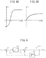
- FIG. 9 is a block diagram illustrative of a configuration example of a rate limiter
- FIG. 10 is a timing diagram illustrative of an operation example of the rate limiter
- FIGS. 11A and 11B are characteristic diagrams for a description of limiting regions of limiters
- FIG. 12 is a characteristic diagram illustrative of an example of characteristics of a k 0 (spring constant) table
- FIG. 13 is a configuration diagram illustrative of a calculation example of an absolute steering angle
- FIG. 14 is a flowchart illustrative of an operation example (the first embodiment) of the present invention.
- FIG. 15 is a flowchart illustrative of an operation example of a shifting steering angle calculation unit (A);
- FIG. 16 is a flowchart illustrative of an operation example of a shifting steering angle calculation unit (B);
- FIG. 17 is a flowchart illustrative of an operation example of a feedforward (FF) control unit
- FIG. 18 is a block diagram illustrative of another configuration example (second embodiment) of the present invention.
- FIG. 19 is a block diagram illustrative of still another configuration example (third embodiment) of the present invention.
- FIG. 20 is a block diagram illustrative of still another configuration example (fourth embodiment) of the present invention.
- FIG. 21 is a block diagram illustrative of still another configuration example (fifth embodiment) of the present invention.
- FIG. 22 is a block diagram illustrative of still another configuration example (eighth embodiment) of the present invention.
- FIGS. 23A and 23B are characteristic diagrams illustrative of examples of characteristics of a steering angular velocity calculation unit and a steering angle correction amount calculation unit, respectively;
- FIG. 24 is a block diagram illustrative of still another configuration example (ninth embodiment) of the present invention.
- FIG. 25 is a characteristic diagram illustrative of an example of characteristics of a gain unit (proportional (P) control unit);
- FIG. 26 is a block diagram illustrative of still another configuration example (tenth embodiment) of the present invention.
- FIG. 27 is a diagram illustrative of an operation example of the tenth embodiment.
- FIG. 28A is a block diagram illustrative of a configuration example of a control steering angle shifting unit 120 of an eleventh embodiment
- FIG. 28B is a characteristic diagram illustrative of an example of characteristics of a gain setting unit of the control steering angle shifting unit 120 .
- the present invention relates to control that, in order to suppress impact and abnormal noise at the time of end-abutting at a rack end, generates rack end control output (reaction force) and forms a virtual rack end and, by reducing the rack end control output (reaction force) in the vicinity of the virtual rack end, enables a driver to turn the steering wheel to the rack end without stress and prevents steering control from influencing the turning radius of a vehicle.
- the present invention by detecting intention of the driver to further turn the steering wheel while the reaction force has increased, using steering torque, and correcting control rotational displacement to be input to an end-abutting impact mitigation control unit according to the steering torque and steering velocity in such a way that the absolute value of the control rotational displacement decreases and thereby reducing the reaction force, increases assist force and thereby enable the driver to turn the steering wheel to the rack end.
- the end-abutting impact mitigation control at a rack end is configured to be a function based on the control rotational displacement from a steering angle at which the rack end control is started and generates larger output as the control rotational displacement increases in such a way as to be able to prevent impact and abnormal noise at the time of end-abutting from occurring.
- the output of the end-abutting impact mitigation control is kept at a high level, assist torque of an electric power steering decreases, there is a possibility that the driver cannot turn the steering wheel to a physical rack end and the minimum turning radius of the vehicle increases.
- the end-abutting impact mitigation control unit in the present invention is set in such a way that the larger the control rotational displacement becomes, the larger generated output becomes, performing correction in such away that the absolute value of the control rotational displacement to be input to the end-abutting impact mitigation control unit decreases enables end-abutting impact mitigation control output to be reduced and an assist control amount (assist torque) to be increased. Setting a correction amount appropriately on this occasion enables the driver to achieve steering without impact caused by end-abutting even when the steering angle reaches the physical rack end.
- a target steering velocity based on steering torque and a steering angle sign (whether the steering angle is positive or negative) is calculated, and a first rotational displacement correction amount (steering angle for shifting) is calculated by a proportional-integral-differential (PID) controller (or at least one of a proportional controller, an integral controller, and a differential controller) with respect to velocity deviation between the target steering velocity and an actual steering velocity (the A-side in a feedback (FB) form).
- PID proportional-integral-differential
- FB feedback
- a second rotational displacement correction amount (steering angle for shifting) is calculated with respect to a steering angle correction amount based on the steering torque and the steering angle sign (whether the steering angle is positive or negative), and, in conjunction therewith, since, when the amount of change in the correction amount becomes excessive, impact occurs when the steering angle has reached the physical rack end, a rate limiter is disposed in a correction amount calculation path (the B-side in a feedforward (FF) form). As with the A-side, a limiter for the correction amount is disposed lest the absolute value of the correction amount becomes excessive.
- a rotational displacement correction amount (shift steering angle amount) is calculated by adding the first rotational displacement correction amount to the second rotational displacement correction amount, and the control rotational displacement to be input to the FF control unit including the end-abutting impact mitigation control unit is corrected by the rotational displacement correction amount.
- the output is reduced. Since configuring an embodiment in this manner causes the reaction force to decrease and the assist force to be restored, it becomes possible to turn the steering wheel to the physical rack end.
- the first rotational displacement correction amount on the FB side (A-side) is calculated according to normalized steering torque that is obtained by multiplying the steering torque by a sign of the control rotational displacement and thereby normalizing the steering torque in such a way that the steering torque is “positive” at the time of the driver further turning the steering wheel and “negative” at the time of the driver returning the steering wheel.
- a normalized target steering velocity is set in such a way that the larger the normalized steering torque is, the larger the normalized target steering velocity becomes.
- the normalized target steering velocity is steering velocity that is defined in such a way that the steering velocity at the time of the driver further turning the steering wheel becomes “positive” and the steering velocity at the time of the driver returning the steering wheel becomes “negative”, and, when the driver takes his/her hands off the steering wheel (the steering torque is substantially zero), the normalized target steering velocity becomes a negative value because the steering wheel is returned toward the center position because of road surface reaction force.
- the target steering velocity having an actual sign is calculated.
- a rotational displacement correction amount is calculated.
- a maximum value of the normalized target steering velocity is set at a value that does not cause impact to occur even when the steering angle reaches a physical rack end.
- a correction amount is also calculated by multiplying an amount based on the steering torque by the sign of the control rotational displacement.
- the corrected control rotational displacement becomes “negative” despite the control rotational displacement being “positive”. Since outputting a “negative” value as an output for the end-abutting impact mitigation control while the control rotational displacement is “positive” does not conform to the functional objective of the end-abutting impact mitigation control, a limiter that does not cause the corrected control rotational displacement to become “negative” while the control rotational displacement is “positive” is disposed.
- the limiter may be disposed for each of the first rotational displacement correction amount and the second rotational displacement correction amount or disposed at the succeeding stage to a stage for adding the first rotational displacement correction amount to the second rotational displacement correction amount.
- Rack axial force and column shaft torque are equivalent to each other, and the present invention is configured to, by detecting intention of a driver to further turn the steering wheel while the reaction force has increased, using the steering torque or the rack axial force, which is an indication of the intention, and adjusting shift control steering angle to be input to an end-abutting impact mitigation control unit and thereby reducing reaction force, enable the driver to turn the steering wheel to a rack end (or a close range thereof).
- FIG. 7 illustrates an example of an embodiment (first embodiment) of the present invention in a corresponding manner to FIG. 3 , and, in the first embodiment, a virtual rack end control unit 100 A that takes steering angle ⁇ and steering torque Th as input and outputs a current command value Iref 2 is included, the virtual rack end control unit 100 A being constituted by an input processing/determination unit 101 configured to take the steering angle ⁇ as input, determine a rack end, and output control rotational displacement ⁇ r and steering velocity ⁇ , a control steering angle shifting unit 120 configured to take the control rotational displacement ⁇ r, the steering velocity ⁇ , and the steering torque Th as input and output a shift control steering angle ⁇ rs for shift control, and a feedforward (FF) control unit 160 configured to take the steering velocity ⁇ from the input processing/determination unit 101 and the shift control steering angle ⁇ rs from the control steering angle shifting unit 120 as input and output a current command value Iref 2 , the FF control unit 160 being constituted by an end-abutting impact mitigation control
- the control steering angle shifting unit 120 includes a sign determination unit 126 configured to determine whether the control rotational displacement ⁇ r is positive or negative and output a sign SN representing a result of the determination and also includes a shifting steering angle calculation unit (A) 124 A on the A-side configured to calculate a steering angle ⁇ a3 for shifting by means of an FB function, based on the sign SN, the steering torque Th, and the steering velocity ⁇ and a shifting steering angle calculation unit (B) 124 B on the B-side configured to calculate a steering angle ⁇ b4 for shifting by means of an FF function, based on the sign SN and the steering torque Th.
- A shifting steering angle calculation unit
- B shifting steering angle calculation unit
- the addition unit 125 and the subtraction unit 122 constitute a shift control unit.
- the sign determination unit 126 may be configured to take the steering angle ⁇ as input and output the sign SN.
- the shifting steering angle calculation unit (A) 124 A is constituted by a multiplication unit 124 A- 1 configured to multiply the steering torque Th by the sign SN, a target steering angular velocity calculation unit 124 A- 2 configured to calculate a target steering angular velocity ⁇ ra1 based on a multiplication result (Th ⁇ SN) by the multiplication unit 124 A- 1 in accordance with characteristics as illustrated in FIG.
- a multiplication unit 124 A- 3 configured to multiply the target steering angular velocity ⁇ ra1 by the sign SN
- a subtraction unit 124 A- 4 configured to calculate a velocity deviation ⁇ ra3 by subtracting the steering velocity ⁇ from target steering angular velocity ⁇ ra2 that is a multiplication result ( ⁇ ra1 ⁇ SN) by the multiplication unit 124 A- 3
- a proportional processing unit 124 A- 5 configured to perform proportional control (may perform at least one of proportional control (P), integral control (I), and differential control (D)) on the velocity deviation ⁇ ra3
- a rate limiter 124 A- 6 configured to perform rate-limiting processing (smoothing) on an angle ⁇ a1 for shift calculation that has been subjected to the proportional control
- a limiter 124 A- 7 configured to limit a shift amount of an angle ⁇ a1 for shift calculation that has
- the shifting steering angle calculation unit (B) 124 B is constituted by a multiplication unit 124 B- 1 configured to multiply the steering torque Th by the sign SN, a steering angle correction amount calculation unit 124 B- 2 configured to calculate a steering angle correction amount ⁇ b1 based on a multiplication result (Th ⁇ SN) by the multiplication unit 124 B- 1 in accordance with characteristics as illustrated in FIG.
- a multiplication unit 124 B- 3 configured to multiply the angle ⁇ b1 for shift calculation output from the steering angle correction amount calculation unit 124 B- 2 by the sign SN and output an angle ⁇ b2 for shift calculation
- a rate limiter 124 B- 4 configured to perform rate-limiting processing (smoothing) on the angle ⁇ b2 for shift calculation output from the multiplication unit 124 B- 3
- a limiter 124 B- 5 configured to limit a shift amount of an angle ⁇ b3 for shift calculation that has been subjected to the rate-limiting processing by the rate limiter 124 B- 4 and output the steering angle ⁇ b4 for shifting.
- the rate limiter 124 A- 6 and the rate limiter 124 B- 4 are not indispensable components.
- the target steering angular velocity calculation unit 124 A- 2 may calculate the target steering angular velocity ⁇ ra1 , based on, in place of the multiplication result (Th ⁇ SN) of the steering torque Th and the sign SN, a multiplication result of the rack axial force and the sign SN and output the calculated target steering angular velocity ⁇ ra1 .
- the shifting steering angle calculation unit (B) 124 B may calculate the steering angle correction amount ⁇ b1 , based on, in place of the multiplication result (Th ⁇ SN) of the steering torque Th and the sign SN, a multiplication result of the rack axial force and the sign SN and output the calculated steering angle correction amount ⁇ b1 .
- the target steering angular velocity calculation unit 124 A- 2 calculates the target steering angular velocity ⁇ ra1 , based on the multiplication result of the steering torque Th and the sign SN and outputs the calculated target steering angular velocity ⁇ ra1 , the target steering angular velocity ⁇ ra1 is input to the multiplication unit 124 A- 3 and multiplied by the sign SN, the target steering angular velocity ⁇ ra2 that is a multiplication result is subjected to subtraction of the steering velocity ⁇ therefrom by the subtraction unit 124 A- 4 and the velocity deviation ⁇ ra3 is thereby calculated, the velocity deviation ⁇ ra3 passes through the proportional control unit (P) 124 A- 5 and is thereby converted to the angle ⁇ a1 for shift calculation, the angle ⁇ a1 for shift calculation is input to the rate limiter 124 A- 6 , the angle ⁇ a2 for shift calculation that has been subject
- the steering angle correction amount calculation unit 124 B- 2 calculates a steering angle correction amount ⁇ b1 based on a multiplication result of the steering torque Th and the sign and outputs the calculated steering angle correction amount ⁇ b1 , the steering angle correction amount ⁇ b1 is input to the multiplication unit 124 B- 3 and multiplied by the sign SN, the angle ⁇ b2 for shift calculation that is a multiplication result is input to the rate limiter 124 B- 4 , the angle ⁇ b3 for shift calculation that has been subjected to the rate-limiting processing is further input to the limiter 124 B- 5 , and the steering angle ⁇ b4 for shifting obtained by limiting the shift amount of the angle ⁇ b3 for shift calculation is output.
- the reason for multiplying the steering torque Th by the sign SN of the control rotational displacement ⁇ r in the shifting steering angle calculation unit (A) 124 A and the shifting steering angle calculation unit (B) 124 B is because the steering torque Th in the case where the directions of the steering torque Th and the control rotational displacement ⁇ r coincide with each other (at the time of the driver further turning the steering wheel) is defined to be “positive” and the steering torque Th in the case where the directions of the steering torque Th and the control rotational displacement ⁇ r do not coincide with each other (at the time of the driver returning the steering wheel) is defined to be “negative”.
- a single multiplication unit may be configured to serve as both the multiplication unit of the A-side and the multiplication unit of the B-side.
- the rate limiters 124 A- 6 and 124 B- 4 have the same configuration and are configured to limit the amounts of change in the angles between control periods and thereby output smooth angles because abrupt changes in the angles cause rapid fluctuation in the control constants and rapid fluctuation in the control outputs. Although the rate limiter 124 A- 6 will be described below, the same applied to the rate limiter 124 B- 4 .
- the rate limiter 124 A- 6 is configured such that the angle ⁇ a1 for shift calculation is input to a subtraction unit 124 - 1 as a positive input and subjected to subtraction of a past value input from a holding unit (Z ⁇ 1 ) 124 - 4 therefrom by the subtraction unit 124 - 1 and an angle ⁇ a1n that is a subtraction result is limited by an upper limit and a lower limit by a change angle setting unit 124 - 2 and output as a change angle ⁇ a1m , as illustrated in FIG. 9 .
- the change angle setting unit 124 - 2 is a unit configure to prevents the change angle from exceeding the upper limit and the lower limit and has characteristics of, by repeating limiting a difference between the input angle ⁇ a1 and a past value by the upper limit and the lower limit and calculating an added value of the limited change angle ⁇ a1m and the past value and, when the difference ⁇ a1n is out of range between the upper limit and the lower limit of the change setting unit 124 - 2 , limiting the difference ⁇ a1n by the upper limit and the lower limit and adding the limited change ⁇ a1m to the limited past value at every calculation period T, changing the output ⁇ a2 in a staircase pattern as illustrated in FIG.
- the limiters 124 A- 7 and 124 B- 5 which have characteristics illustrated in FIGS. 11A and 11B , are disposed, respectively.
- Both the limiters 124 A- 7 and 124 B- 5 have a function of limiting a shift amount, and, regarding the limiter 124 A- 7 , the shaded area in FIG. 11A is a region in which an input value is limited and, regarding the limiter 124 B- 5 , the shaded area in FIG. 11B is a region in which an input value is limited.
- the limiter 124 A- 7 has different characteristics between the positive side and the negative side, and larger limit values are set on the positive side than on the negative side.
- the limiter 124 B- 5 has limit values set only on the positive side and has characteristics of cutting off all values on the negative side.
- the limiter 124 A- 7 has characteristics of causing the output ( ⁇ a2 ) to constantly have positive values and gradually increase nonlinearly on the positive side of the angle ⁇ a2 for shift calculation ( ⁇ a2 >0) and to gradually increase in nonlinear characteristics smaller than on the positive side on the negative side of the angle ⁇ a2 for shift calculation ( ⁇ a2 ⁇ 0), as illustrated in FIG. 11A .
- the limiter 124 B- 5 has characteristics of causing the output ( ⁇ b4 ) to constantly have positive values and gradually increase nonlinearly on the positive side of the angle ⁇ b3 for shift calculation ( ⁇ b3 >0) and to constantly have “0” on the negative side of the angle ⁇ b3 for shift calculation ( ⁇ b3 ⁇ 0), as illustrated in FIG. 11B .
- the characteristics of the limiters 124 A- 7 and 124 B- 5 are characteristics obtained by rotating the characteristics in FIGS. 11A and 11B 180° about the origins thereof, respectively.
- the shift control steering angle ⁇ rs is input to a k 0 table 151 , a ⁇ table 152 , and a multiplication unit 153 in the end-abutting impact mitigation control unit 150 , and the steering velocity ⁇ is input to a multiplication unit 154 in the end-abutting impact mitigation control unit 150 .
- a spring constant k 0 in the k 0 table 151 has characteristics represented by an S-shaped gradually increasing curve as illustrated in FIG. 12 and gradually increases as the shift control steering angle ⁇ rs increases, and a viscosity coefficient ⁇ in the ⁇ table 152 has characteristics represented by a gentle curve-shaped gradually increasing curve as illustrated in FIG. 12 and gradually increases as the shift control steering angle ⁇ rs increases.
- the spring constant k 0 that is output from the k 0 table 151 according to the shift control steering angle ⁇ rs is multiplied by the shift control steering angle ⁇ rs by the multiplication unit 153 and input to an addition unit 155
- the viscosity coefficient ⁇ that is output from the ⁇ table 152 according to the shift control steering angle ⁇ rs is multiplied by the steering velocity ⁇ by the multiplication unit 154 and input to the addition unit 155 .
- the end-abutting impact mitigation current command value Ireff that is an addition result by the addition unit 155 passes through a current output unit that is constituted by the output limiter 161 and the inverting unit 162 and is input to an addition unit 33 as the current command value Iref 2 .
- a current command value Iref 1 is corrected by the addition unit 33
- a corrected current command value Iref 3 is input to a subtraction unit 32 as a positive input as a new current command value.
- the steering angle ⁇ to be input to the virtual rack end control unit 100 A can be acquired from a rotation angle sensor 25
- the steering angle ⁇ can also be acquired from an angle sensor that has a configuration as illustrated in FIG. 13 .
- a Hall IC sensor 21 serving as an angle sensor and a 20° rotor sensor 22 that is an input-side rotor of a torque sensor are mounted.
- the Hall IC sensor 21 outputs an AS_IS angle ⁇ h with a period of 296°.
- the 20° rotor sensor 22 which is mounted on the steering wheel 1 side of a torsion bar 23 , outputs a column input-side angle signal ⁇ s with a period of 20°, and the column input-side angle signal ⁇ s is input to a steering angle calculation unit 50 .
- a 40° rotor sensor 24 that is an output-side rotor of the torque sensor is mounted on an output shaft 2 B of the column shaft 2 , a column output-side angle signal ⁇ r is output from the 40° rotor sensor 24 , and the column output-side angle signal ⁇ r is input to the steering angle calculation unit 50 .
- the column input-side angle signal ⁇ s and the column output-side angle signal ⁇ r which are detected in this way, are input to the steering angle calculation unit 50 , and the steering angle ⁇ is calculated.
- the shifting steering angle calculation unit (A) 124 A outputs the steering angle ⁇ a3 for shifting according to the target steering angular velocity ⁇ ra1 , and the subtraction unit 122 reduces the impact mitigation current command value Ireff by subtracting the steering angle ⁇ a3 for shifting from the control rotational displacement ⁇ r. Therefore, by limiting a condition allowing reduction of the impact mitigation current command value Ireff depending on the steering angular velocity, it is possible to prevent impact sound from being generated at the time of end-abutting caused by reducing the impact mitigation current command value Ireff when the steering angular velocity is large.
- the shifting steering angle calculation unit (B) 124 B outputs the steering angle ⁇ b4 for shifting according to the steering angle correction amount based on the steering torque Th, and the subtraction unit 122 reduces the impact mitigation current command value Ireff by subtracting the steering angle ⁇ b4 for shifting from the control rotational displacement ⁇ r. Therefore, it becomes possible to reduce the impact mitigation current command value Ireff when the steering torque Th has become large to a certain extent, and it is thus possible to avoid a sudden change in the current command value at the start time of the impact mitigation control and suppress a sense of discomfort.
- control steering angle shifting unit 120 does not necessarily have to include both the shifting steering angle calculation unit (A) 124 A and the shifting steering angle calculation unit (B) 124 B and may include either thereof. The same applies to other embodiments.
- steering torque Th, vehicle speed Vs, and steering angle ⁇ are input (step S 1 ), and a current command value Iref 1 is calculated in a basic assist characteristic calculation unit 31 (step S 2 ).
- the input processing/determination unit 101 calculates and outputs a steering velocity ⁇ and a control rotational displacement ⁇ r, based on the steering angle ⁇ (step S 3 ).
- the steering velocity ⁇ is input to the subtraction unit 124 A- 4 in the control steering angle shifting unit 120 and the multiplication unit 154 in the end-abutting impact mitigation control unit 150
- the control rotational displacement ⁇ r is input to the sign determination unit 126 in the control steering angle shifting unit 120 and, in conjunction therewith, input to the subtraction unit 122 as a positive input.
- the sign determination unit 126 determines a sign (positive or negative) of the control rotational displacement ⁇ r and outputs a sign SN (step S 4 ).
- the sign SN is input to the multiplication unit 124 A- 1 and the multiplication unit 124 A- 3 in the shifting steering angle calculation unit (A) 124 A and the multiplication unit 124 B- 1 and the multiplication unit 124 B- 3 in the shifting steering angle calculation unit (B) 124 B.
- the steering torque Th is input to the multiplication unit 124 A- 1 in the shifting steering angle calculation unit 124 A and the multiplication unit 124 B- 1 in the shifting steering angle calculation unit 124 B and is multiplied by the sign SN by the multiplication unit 124 A- 1 and the multiplication unit 124 B- 1 .
- a multiplication result by the multiplication unit 124 A- 1 is input to the target steering angular velocity calculation unit 124 A- 2 in the shifting steering angle calculation unit 124 A, a target steering angular velocity ⁇ ra1 is calculated in accordance with characteristics as illustrated in FIG.
- a steering angle ⁇ a3 for shifting on the FB side is calculated in a manner to be described later and output (step S 10 ), and, in conjunction therewith, a multiplication result by the multiplication unit 124 B- 1 is input to the steering angle correction amount calculation unit 124 B- 2 in the shifting steering angle calculation unit 124 B, a steering angle correction amount ⁇ b1 is calculated in accordance with characteristics as illustrated in FIG. 8B , and a steering angle ⁇ b4 for shifting on the FF side is calculated in a manner to be described later and output (step S 20 ).
- the steering angle ⁇ a3 for shifting from the shifting steering angle calculation unit 124 A and the steering angle ⁇ b4 for shifting from the shifting steering angle calculation unit 124 B are input to the addition unit 125 and added (step S 30 ), and a steering angle ⁇ t for shifting obtained by the addition is input to subtraction unit 122 as a negative input.
- the subtraction unit 122 subtracts the steering angle ⁇ t for shifting from the control rotational displacement ⁇ r and thereby calculates a shift control steering angle ⁇ rs (step S 31 ), and the shift control steering angle ⁇ rs is input to the end-abutting impact mitigation control unit 150 in the FF control unit 160 and subjected to end-abutting impact mitigation processing, using the steering velocity ⁇ (step S 40 ).
- a current command value Ireff that has been subjected to the end-abutting impact mitigation processing has a maximum value thereof limited by the output limiter 161 , and a current command value Irefm obtained by limiting a maximum value of the current command value Ireff is inverted ( ⁇ 1) by the inverting unit 162 and input to the addition unit 33 as a current command value Iref 2 (step S 50 ).
- the current command values Iref 1 and Iref 2 are added by the addition unit 33 and a current command value Iref 3 is thereby calculated (step S 51 ), and assist control of the steering system is performed based on the current command value Iref 3 (step S 52 ).
- step S 10 in FIG. 14 an operation example of the shifting steering angle calculation unit 124 A on the FB side (step S 10 in FIG. 14 ) will be described with reference to a flowchart in FIG. 15 .
- the steering torque Th and the sign SN from the sign determination unit 126 are input to the multiplication unit 124 A- 1 (step S 11 ), and multiplication of the steering torque Th and the sign SN is performed by the multiplication unit 124 A- 1 (step S 12 ).
- a multiplication result by the multiplication unit 124 A- 1 is input to the target steering angular velocity calculation unit 124 A- 2 and the target steering angular velocity calculation unit 124 A- 2 calculates a target steering angular velocity ⁇ ra1 in accordance with characteristics as illustrated in FIG.
- step S 13 the target steering angular velocity ⁇ ra1 is input to the multiplication unit 124 A- 3 and multiplied by the sign SN (step S 14 ), and a target steering angular velocity ⁇ ra2 that is a multiplication result is input to the subtraction unit 124 A- 4 as a positive input and a velocity deviation ⁇ ra3 between the target steering angular velocity ⁇ ra2 and the steering velocity ⁇ is calculated (step S 15 ).
- the velocity deviation ⁇ ra3 is input to the proportional unit 124 A- 5 and subjected to the proportional control (step S 16 ), an angle ⁇ a1 for shift calculation that is an output from the the proportional unit 124 A- 5 is subjected to the rate-limiting processing by the rate limiter 124 A- 6 (step S 17 ), and an angle ⁇ a2 for shift calculation that has been subjected to the rate-limiting processing is input to the limiter 124 A- 7 and subjected to the above-described limiting processing (step S 18 ).
- the steering angle ⁇ a3 for shifting the shift amount of which has been limited is output from the limiter 124 A- 7 (step S 19 ).
- step S 20 in FIG. 14 an operation example of the shifting steering angle calculation unit 124 B on the FF side (step S 20 in FIG. 14 ) will be described with reference to a flowchart in FIG. 16 .
- the steering torque Th and the sign SN from the sign determination unit 126 are input to the multiplication unit 124 B- 1 (step S 21 ), and multiplication of the steering torque Th and the sign SN is performed by the multiplication unit 124 B- 1 (step S 22 ).
- a multiplication result by the multiplication unit 124 B- 1 is input to the steering angle correction amount calculation unit 124 B- 2 and the steering angle correction amount calculation unit 124 B- 2 calculates a steering angle correction amount ⁇ b1 in accordance with characteristics as illustrated in FIG.
- step S 23 the steering angle correction amount ⁇ b1 is input to the multiplication unit 124 B- 3 and multiplied by the sign SN (step S 24 ), an angle ⁇ b2 for shift calculation that is a multiplication result is input to the rate limiter 124 B- 4 and subjected to the rate-limiting processing (step S 25 ), and an angle ⁇ b3 for shift calculation that has been subjected to the rate-limiting processing is input to the limiter 124 B- 5 and subjected to the above-described limiting processing (step S 26 ).
- the steering angle ⁇ b4 for shifting the shift amount of which has been limited is output from the limiter 124 B- 5 (step S 27 ).
- step S 40 in FIG. 14 an operation example of the feedforward (FF) control unit 160 (step S 40 in FIG. 14 ) will be described with reference to a flowchart in FIG. 17 .
- the shift control steering angle ⁇ rs is input from the control steering angle shifting unit 120 and, in conjunction therewith, the steering velocity ⁇ is input from the input processing/determination unit 101 (step S 41 ), a spring constant k 0 is calculated in the k 0 table 151 in accordance with characteristics illustrated in FIG. 12 (step S 42 ), and a viscosity coefficient ⁇ is calculated in the ⁇ table 152 (step S 43 ).
- the order of the calculation may be reversed.
- the spring constant k 0 is input to the multiplication unit 153 and multiplied by the shift control steering angle ⁇ rs, and the viscosity coefficient ⁇ is input to the multiplication unit 154 and multiplied by the steering velocity ⁇ (step S 44 ).
- the respective multiplication results by the multiplication units 153 and 154 are input to the addition unit 155 and added (step S 45 ), and the addition result is output as the end-abutting impact mitigation current command value Ireff (step S 46 ).
- the end-abutting impact mitigation current command value Ireff is subjected to the limiting processing by the output limiter 161 (step S 47 ), and the current command value Irefm that has been subjected to the limiting processing is inverted by the inverting unit 162 (step S 48 ) and output as the current command value Iref 2 (step S 49 ).
- the limiters 124 A- 7 and 124 B- 5 for shift amount limitation are disposed at the succeeding stages to the rate limiters 124 A- 6 and 124 B- 4 , respectively, the limiters 124 A- 7 and 124 B- 5 may be disposed at the preceding stages to the rate limiters 124 A- 6 and 124 B- 4 , respectively, as illustrated in FIG. 18 (second embodiment).
- a limiter 124 A- 7 arranged at the preceding stage to a proportional control unit 124 A- 5 and may be configured to limit an angle ⁇ a4 for shift calculation that is input to the proportional control unit 124 A- 5 , as illustrated in FIG. 19 (third embodiment). Further, it may be configured such that the limiters 124 A- 7 and 124 B- 5 in the shifting steering angle calculation units 124 A and 124 B in the first embodiment in FIG. 7 are deleted, and, as illustrated in FIG.
- a steering angle ⁇ a2 for shifting from the rate limiter 124 A- 6 and a steering angle ⁇ b3 for shifting from the rate limiter 124 B- 4 are added by the addition unit 125 , a steering angle ⁇ ta for shifting that is obtained by the addition is limited by a limiter 127 , and a shift steering angle amount ⁇ tb the shift amount of which is limited is input to the subtraction unit 122 (fourth embodiment).
- the ⁇ table 152 calculates a viscosity coefficient ⁇ , based on the shift control steering angle ⁇ rs
- the ⁇ table 152 may be configured to calculate a viscosity coefficient ⁇ , based on the control rotational displacement ⁇ r, as illustrated in FIG. 21 in a corresponding manner to FIG. 7 (fifth embodiment).
- the arrangement of limiters can also be appropriately changed, as with the second to fourth embodiments.
- first to fifth embodiments includes two shifting steering angle calculation units, namely the shifting steering angle calculation unit (A) 124 A and the shifting steering angle calculation unit (B) 124 B, only the shifting steering angle calculation unit (A) 124 A may be included (sixth embodiment) or only the shifting steering angle calculation unit (B) 124 B may be included (seventh embodiment).
- first to seventh embodiments can be appropriately combined.
- FIG. 22 illustrates an eighth embodiment of the present invention in a corresponding manner to FIG. 7 , and, in the eighth embodiment, vehicle speed Vs is input to a target steering angular velocity calculation unit 124 A- 2 and a steering angle correction amount calculation unit 124 B- 2 as parameters.
- the target steering angular velocity calculation unit 124 A- 2 in the eighth embodiment has characteristics that target steering angular velocity ⁇ ra1 decreases as the vehicle speed Vs increases as illustrated in, for example, FIG. 23A
- the steering angle correction amount calculation unit 124 B- 2 has characteristics that a steering angle correction amount ⁇ b1 decreases as the vehicle speed Vs increases as illustrated in, for example, FIG. 23B .
- Each of the characteristics may be opposite to the above-mentioned with respect to the vehicle speed Vs.
- the respective output characteristics of the target steering angular velocity calculation unit 124 A- 2 and the steering angle correction amount calculation unit 124 B- 2 are configured to respond to the vehicle speed Vs, it may be configured such that, as illustrated in FIG. 24 , a gain unit 124 B- 6 is disposed at the succeeding stage to a multiplication unit 124 B- 3 , that is, at the preceding stage to a rate limiter 124 B- 4 , and a proportional control unit (P) 124 A- 5 and the gain unit 124 B- 6 have gains that are variable according to the vehicle speed Vs (ninth embodiment).
- the gain unit 124 B- 6 that responds to the vehicle speed Vs has characteristics that, as illustrated in FIG.
- gain G decreases linearly (#1) or nonlinearly (#2) as the vehicle speed Vs increases.
- the gain unit 124 B- 6 may have characteristics that the gain G increases linearly or nonlinearly as the vehicle speed Vs increases.
- the same applies to the proportional control unit (P) 124 A- 5 and the proportional control unit (P) 124 A- 5 has characteristics that the gain thereof responds to the vehicle speed Vs.
- the arrangement of limiters can also be appropriately changed.
- the gain is configured to be variable according to the vehicle speed Vs, it may be configured such that, as illustrated in FIG. 26 , the gains of the proportional control unit 124 A- 5 and the gain unit 124 B- 6 are variable according to control rotational displacement ⁇ r (tenth embodiment).
- a proportional control unit 124 A- 5 and a gain unit 124 B- 6 have characteristics that gains thereof respond to control rotational displacement ⁇ r.
- the arrangement of limiters can also be appropriately changed.
- FIG. 28A is a block diagram illustrative of a configuration example of a control steering angle shifting unit 120 of an eleventh embodiment.
- the control steering angle shifting unit 120 may determine a correction gain G, based on a multiplication result (Th ⁇ SN) of steering torque Th and a sign SN and calculate a control rotational displacement ⁇ r corrected by the correction gain G as a shift control steering angle ⁇ rs.
- the control steering angle shifting unit 120 of the eleventh embodiment includes a multiplication unit 124 C- 1 configured to multiply the steering torque Th by the sign SN, a gain setting unit 124 C- 2 configured to set gain G in accordance with characteristics as illustrated in FIG. 28B according to a multiplication result (Th ⁇ SN) by the multiplication unit 124 C- 1 , and a multiplication unit 124 C- 3 configured to calculate a shift control steering angle ⁇ rs by multiplying the gain G by the control rotational displacement ⁇ r.
- the control steering angle shifting unit 120 of the eleventh embodiment may appropriately include a limiter and a rate limiter configured to limit the gain G and a change rate thereof.
- the eleventh embodiment also enables the control rotational displacement ⁇ r to be reduced and an impact mitigation current command value Ireff to be decreased according to the steering torque Th.
- the present invention is also applicable to steer-by-wire in which the steering wheel and a mechanism to turn tires are separated.
Applications Claiming Priority (4)
| Application Number | Priority Date | Filing Date | Title |
|---|---|---|---|
| JP2018234462 | 2018-12-14 | ||
| JPJP2018-234462 | 2018-12-14 | ||
| JP2018-234462 | 2018-12-14 | ||
| PCT/JP2019/048792 WO2020122200A1 (fr) | 2018-12-14 | 2019-12-12 | Dispositif de direction assistée électrique |
Publications (2)
| Publication Number | Publication Date |
|---|---|
| US20210245800A1 US20210245800A1 (en) | 2021-08-12 |
| US11377141B2 true US11377141B2 (en) | 2022-07-05 |
Family
ID=71076504
Family Applications (1)
| Application Number | Title | Priority Date | Filing Date |
|---|---|---|---|
| US17/260,737 Active US11377141B2 (en) | 2018-12-14 | 2019-12-12 | Electric power steering device |
Country Status (5)
| Country | Link |
|---|---|
| US (1) | US11377141B2 (fr) |
| EP (1) | EP3808639B1 (fr) |
| JP (1) | JP6835301B2 (fr) |
| CN (1) | CN112739605B (fr) |
| WO (1) | WO2020122200A1 (fr) |
Cited By (1)
| Publication number | Priority date | Publication date | Assignee | Title |
|---|---|---|---|---|
| US20220089214A1 (en) * | 2020-09-24 | 2022-03-24 | Jtekt Corporation | Steering control device |
Families Citing this family (6)
| Publication number | Priority date | Publication date | Assignee | Title |
|---|---|---|---|---|
| DE102018119268B4 (de) * | 2018-08-08 | 2020-11-05 | Thyssenkrupp Ag | Zahnstangenkraft optimiertes Lenkgefühl einer Steer-by-Wire-Kraftfahrzeuglenkung |
| JP7376290B2 (ja) * | 2019-09-10 | 2023-11-08 | 株式会社ジェイテクト | 操舵制御装置 |
| US11654956B2 (en) * | 2019-12-23 | 2023-05-23 | Robert Bosch Gmbh | Method and system for steering intervention by electronic power steering unit to prevent vehicle rollover or loss of control |
| JP7307000B2 (ja) * | 2020-01-27 | 2023-07-11 | 株式会社ジェイテクト | 操舵制御装置 |
| EP3875350A1 (fr) * | 2020-03-06 | 2021-09-08 | Zenuity AB | Procédé et agencement pour assurer le suivi de la route jusqu'à une limite d'accélération latérale prédéfinie à l'aide d'un régulateur pid dans un véhicule |
| JP7376407B2 (ja) * | 2020-03-27 | 2023-11-08 | 株式会社ジェイテクト | 操舵制御装置 |
Citations (13)
| Publication number | Priority date | Publication date | Assignee | Title |
|---|---|---|---|---|
| US4727950A (en) | 1985-02-12 | 1988-03-01 | Honda Giken Koygo Kabushiki Kaisha | Electric power steering system for vehicles |
| US20020166319A1 (en) | 2001-04-17 | 2002-11-14 | Kai Grebe | Method of controlling a power steering system |
| JP2007062584A (ja) | 2005-08-31 | 2007-03-15 | Showa Corp | 電動パワーステアリング装置 |
| US20080243339A1 (en) * | 2007-03-27 | 2008-10-02 | Honda Motor Co., Ltd. | Steering system |
| US20090114470A1 (en) * | 2007-11-06 | 2009-05-07 | Honda Motor Co., Ltd. | Electric power steering device |
| US20140316658A1 (en) * | 2011-10-26 | 2014-10-23 | Nissan Motor Co., Ltd. | Steering control apparatus |
| WO2016104569A1 (fr) | 2014-12-25 | 2016-06-30 | 日本精工株式会社 | Dispositif de direction assistée électrique |
| WO2016125773A1 (fr) | 2015-02-02 | 2016-08-11 | 日本精工株式会社 | Dispositif de détermination de maintien de direction pour véhicules et dispositif de direction assistée électrique fourni avec celui-ci |
| US20170334481A1 (en) | 2014-12-25 | 2017-11-23 | Nsk Ltd. | Electric power steering apparatus |
| JP2017210216A (ja) | 2016-05-27 | 2017-11-30 | 日本精工株式会社 | 電動パワーステアリング装置の制御装置 |
| US20180065660A1 (en) | 2016-09-07 | 2018-03-08 | Denso Corporation | Steering control apparatus |
| US20190173406A1 (en) * | 2017-12-04 | 2019-06-06 | Jtekt Corporation | Inverter device |
| US20200023899A1 (en) * | 2018-07-17 | 2020-01-23 | Toyota Jidosha Kabushiki Kaisha | Lane departure prevention apparatus |
Family Cites Families (6)
| Publication number | Priority date | Publication date | Assignee | Title |
|---|---|---|---|---|
| JP3317361B2 (ja) | 1992-06-23 | 2002-08-26 | 富士電機株式会社 | メモリのバッテリバックアップ制御方式 |
| JP4492230B2 (ja) * | 2004-07-06 | 2010-06-30 | 日産自動車株式会社 | 車両用操舵制御装置 |
| EP2933169B1 (fr) * | 2013-04-04 | 2018-01-10 | NSK Ltd. | Appareil de direction assistee electrique |
| JP6260818B2 (ja) * | 2014-02-18 | 2018-01-17 | 株式会社ジェイテクト | 電動パワーステアリング装置 |
| JP6380693B2 (ja) * | 2016-02-12 | 2018-08-29 | 日本精工株式会社 | 車両用ステアリング制御装置 |
| CN110139793B (zh) * | 2017-02-02 | 2021-05-07 | 日本精工株式会社 | 电动助力转向装置 |
-
2019
- 2019-12-12 EP EP19897315.8A patent/EP3808639B1/fr active Active
- 2019-12-12 US US17/260,737 patent/US11377141B2/en active Active
- 2019-12-12 CN CN201980060629.6A patent/CN112739605B/zh active Active
- 2019-12-12 JP JP2020555539A patent/JP6835301B2/ja active Active
- 2019-12-12 WO PCT/JP2019/048792 patent/WO2020122200A1/fr unknown
Patent Citations (17)
| Publication number | Priority date | Publication date | Assignee | Title |
|---|---|---|---|---|
| US4727950A (en) | 1985-02-12 | 1988-03-01 | Honda Giken Koygo Kabushiki Kaisha | Electric power steering system for vehicles |
| JPH064417B2 (ja) | 1985-02-12 | 1994-01-19 | 本田技研工業株式会社 | 電動式パワーステアリング装置 |
| US20020166319A1 (en) | 2001-04-17 | 2002-11-14 | Kai Grebe | Method of controlling a power steering system |
| JP4115156B2 (ja) | 2001-04-17 | 2008-07-09 | ティーアールダブリュー・ファールヴェルクズュステーメ・ゲーエムベーハー・ウント・コンパニー・カーゲー | パワーステアリングシステムの制御方法 |
| JP2007062584A (ja) | 2005-08-31 | 2007-03-15 | Showa Corp | 電動パワーステアリング装置 |
| US20080243339A1 (en) * | 2007-03-27 | 2008-10-02 | Honda Motor Co., Ltd. | Steering system |
| US20090114470A1 (en) * | 2007-11-06 | 2009-05-07 | Honda Motor Co., Ltd. | Electric power steering device |
| US20140316658A1 (en) * | 2011-10-26 | 2014-10-23 | Nissan Motor Co., Ltd. | Steering control apparatus |
| WO2016104569A1 (fr) | 2014-12-25 | 2016-06-30 | 日本精工株式会社 | Dispositif de direction assistée électrique |
| US20170334481A1 (en) | 2014-12-25 | 2017-11-23 | Nsk Ltd. | Electric power steering apparatus |
| WO2016125773A1 (fr) | 2015-02-02 | 2016-08-11 | 日本精工株式会社 | Dispositif de détermination de maintien de direction pour véhicules et dispositif de direction assistée électrique fourni avec celui-ci |
| US20180009472A1 (en) | 2015-02-02 | 2018-01-11 | Nsk Ltd. | Steering holding judging apparatus for vehicle and electric power steering apparatus equipped with the same |
| JP2017210216A (ja) | 2016-05-27 | 2017-11-30 | 日本精工株式会社 | 電動パワーステアリング装置の制御装置 |
| US20180065660A1 (en) | 2016-09-07 | 2018-03-08 | Denso Corporation | Steering control apparatus |
| JP2018039350A (ja) | 2016-09-07 | 2018-03-15 | 株式会社デンソー | ステアリング制御装置 |
| US20190173406A1 (en) * | 2017-12-04 | 2019-06-06 | Jtekt Corporation | Inverter device |
| US20200023899A1 (en) * | 2018-07-17 | 2020-01-23 | Toyota Jidosha Kabushiki Kaisha | Lane departure prevention apparatus |
Non-Patent Citations (2)
| Title |
|---|
| International Search Report for PCT/JP2019/048792 dated Mar. 10, 2020 (PCT/ISA/210). |
| Written Opinion for PCT/JP2019/048792 dated Mar. 10, 2020 (PCT/ISA/237). |
Cited By (2)
| Publication number | Priority date | Publication date | Assignee | Title |
|---|---|---|---|---|
| US20220089214A1 (en) * | 2020-09-24 | 2022-03-24 | Jtekt Corporation | Steering control device |
| US11964709B2 (en) * | 2020-09-24 | 2024-04-23 | Jtekt Corporation | Steering control device |
Also Published As
| Publication number | Publication date |
|---|---|
| CN112739605B (zh) | 2022-10-04 |
| JPWO2020122200A1 (ja) | 2021-02-15 |
| JP6835301B2 (ja) | 2021-02-24 |
| WO2020122200A1 (fr) | 2020-06-18 |
| EP3808639A4 (fr) | 2021-10-06 |
| CN112739605A (zh) | 2021-04-30 |
| EP3808639B1 (fr) | 2022-05-04 |
| US20210245800A1 (en) | 2021-08-12 |
| EP3808639A1 (fr) | 2021-04-21 |
Similar Documents
| Publication | Publication Date | Title |
|---|---|---|
| US11377141B2 (en) | Electric power steering device | |
| US9821837B2 (en) | Electric power steering apparatus | |
| US9789901B2 (en) | Electric power steering apparatus | |
| CN109572807B (zh) | 电动助力转向装置 | |
| EP3459825B1 (fr) | Dispositif de direction assistée électrique | |
| US9796413B2 (en) | Electric power steering apparatus | |
| CN110139793B (zh) | 电动助力转向装置 | |
| JP4639861B2 (ja) | 電動パワーステアリング装置の制御装置 | |
| CN111315637B (zh) | 电动助力转向装置 | |
| EP3187396B1 (fr) | Procédé de commande de direction assistée électrique, direction assistée électrique, et véhicule équipé de celle-ci | |
| JPWO2010109676A1 (ja) | 車両の操舵装置 | |
| JP5999291B1 (ja) | 電動パワーステアリング装置 | |
| WO2016021526A1 (fr) | Dispositif de direction à assistance électrique | |
| JP6702513B2 (ja) | 車両用操向装置 | |
| WO2015198830A1 (fr) | Dispositif de direction assistée électrique |
Legal Events
| Date | Code | Title | Description |
|---|---|---|---|
| AS | Assignment |
Owner name: NSK LTD., JAPAN Free format text: ASSIGNMENT OF ASSIGNORS INTEREST;ASSIGNORS:KITAZUME, TETSUYA;MARUYAMA, SHOYA;REEL/FRAME:054935/0382 Effective date: 20201221 |
|
| FEPP | Fee payment procedure |
Free format text: ENTITY STATUS SET TO UNDISCOUNTED (ORIGINAL EVENT CODE: BIG.); ENTITY STATUS OF PATENT OWNER: LARGE ENTITY |
|
| STPP | Information on status: patent application and granting procedure in general |
Free format text: NON FINAL ACTION MAILED |
|
| STPP | Information on status: patent application and granting procedure in general |
Free format text: RESPONSE TO NON-FINAL OFFICE ACTION ENTERED AND FORWARDED TO EXAMINER |
|
| STPP | Information on status: patent application and granting procedure in general |
Free format text: FINAL REJECTION MAILED |
|
| STPP | Information on status: patent application and granting procedure in general |
Free format text: ADVISORY ACTION MAILED |
|
| STPP | Information on status: patent application and granting procedure in general |
Free format text: DOCKETED NEW CASE - READY FOR EXAMINATION |
|
| STPP | Information on status: patent application and granting procedure in general |
Free format text: NOTICE OF ALLOWANCE MAILED -- APPLICATION RECEIVED IN OFFICE OF PUBLICATIONS |
|
| STPP | Information on status: patent application and granting procedure in general |
Free format text: PUBLICATIONS -- ISSUE FEE PAYMENT RECEIVED |
|
| STPP | Information on status: patent application and granting procedure in general |
Free format text: PUBLICATIONS -- ISSUE FEE PAYMENT VERIFIED |
|
| STCF | Information on status: patent grant |
Free format text: PATENTED CASE |