US1136851A - Brake for wagons. - Google Patents
Brake for wagons. Download PDFInfo
- Publication number
- US1136851A US1136851A US52989609A US1909529896A US1136851A US 1136851 A US1136851 A US 1136851A US 52989609 A US52989609 A US 52989609A US 1909529896 A US1909529896 A US 1909529896A US 1136851 A US1136851 A US 1136851A
- Authority
- US
- United States
- Prior art keywords
- wheel
- brake
- shoe
- periphery
- arm
- Prior art date
- Legal status (The legal status is an assumption and is not a legal conclusion. Google has not performed a legal analysis and makes no representation as to the accuracy of the status listed.)
- Expired - Lifetime
Links
Images
Classifications
-
- F—MECHANICAL ENGINEERING; LIGHTING; HEATING; WEAPONS; BLASTING
- F16—ENGINEERING ELEMENTS AND UNITS; GENERAL MEASURES FOR PRODUCING AND MAINTAINING EFFECTIVE FUNCTIONING OF MACHINES OR INSTALLATIONS; THERMAL INSULATION IN GENERAL
- F16D—COUPLINGS FOR TRANSMITTING ROTATION; CLUTCHES; BRAKES
- F16D49/00—Brakes with a braking member co-operating with the periphery of a drum, wheel-rim, or the like
- F16D49/16—Brakes with two brake-blocks
Definitions
- My invention has for its object the production of a simple and eflicient brake, particularly applicable for dumping wagons; and it consists in the combinations and constructions hereinafter set forth and claimed.
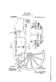
- FIG. 1 is an elevation, partly broken away, of a dumping wagon embodying my invention.
- Fig. 2 is a rear elevation thereof, parts being omitted.
- Fig. 3 is a detail view of one of the brake blocks and contiguous parts.
- This brake comprises generally, a block provided with a concave engaging face for coacting with the periphery or tread of the wagon wheel, such face being normally substantially concentric with said periphery, and means for moving the block toward and from the periphery of the wagon wheel in a substantially tangential direction and holding the block during the movement thereof with its engaging face substantially concentric with said periphery.
- My invention is here shown embodied in a dumping wagon provided with brake blocks located on opposite sides of the body of the wagon for engaging the peripheries or treads of the rear wheels, both blocks being operated by suitable means located on but one side of the wagon body.
- 1 is the body of the wagon; and 2 is one of the rear wheels, the other rear wheel and the front wheels being omitted.
- rock shaft 3 is a rock shaft extending crosswise of the rear end of the wagon body and being here shown as journaled in rearwardly extending brackets & provided on the body 1, the rock shaft being arranged so that its axis is located in a line extending transversely of the wheel and within the same.
- rock arms carried at opposite ends of the rock shaft and extending upwardly and rearwardly and provided with spindles, stubs or pivots 6 at their free ends; and 7 are brake blocks mounted on the spindles 6,
- each block having a concave engaging face 8 for coacting with the periphery of the adjacent rear wheel 2.
- the arms 5 are preferably formed integral with the shaft 3 and extend upwardly and rearwardly from said shaft as seen in Fig. 1. Owing to the arrangement of the rock arms, the brake shoes are arranged to engage the peripheries of the wheels above the horizontal plane intersecting the axle of the wheels, and in the rear of the vertical plane containing such axis.
- the means for actuating each brake block and for holding said block with its engaging face 8 substantially concentric with the periphery of the adjacent wheel 2 during the movement of the brake block into and out of operative position includes a link 9 having its rear end connected to the spindle 6 for the brake block and having an extension or arm 10 whichvis fixed at 11 to the brake block.
- the brake blocks are prevented from tilting on the spindles 6 and are controlled in their movement by the links 9 so that during the movement of the blocks the links hold the blocks with their engaging faces 8 substantially concentric with the peripheries of the wheels 2 and but slight movement or small leverage is necessary to carry the brake blocks away from the wheels.
- the links 9 are connected at their front ends to arms 12 mounted on opposite ends of a rock shaft 13 journaled in the wagon body 1 in front of the rock shaft 3, the rock arm 12 on one side of the body being connected by a link 14 to a hand lever 15 located at the front of the wagon.
- What I claim is 1.
- a brake shoe arranged to engage the periphery of a wheel
- a rock arm pivotally mounted at one end on the vehicle body and the axis thereof being located in a line extending transversely of the wheel within the same
- the shoe bein mounted on the outer end of the arm
- an the arm being arranged to carry the shoe in a tangential direction toward the periphery of the wheel
Landscapes
- Engineering & Computer Science (AREA)
- General Engineering & Computer Science (AREA)
- Mechanical Engineering (AREA)
- Braking Arrangements (AREA)
Description
W. A. UNDERHILL.
BRAKE FOR WAGONS.
APPLICATION men NOV. 26. 1909.
ATTORNEYS Patented Apr. 20, 1915.
WITNESSES:
UNITED STATES PATENT OFTCE.
WALTER A. UNDERI-IILL, OF AUBURN, NEW YORK, ASSIGNOR TO THE EAGLE WAGON WORKS, OF AUBURN, NEW YORK, A CORPORATION OF NEW YORK.
BRAKE FOR WAGONS.
Application filed November 26, 1909.
To all whom it may concern:
Be it known that I, WALTER A. UNDER- HILL, of Auburn, in the county of Cayuga and State of New York, have invented a certain new and useful Brake for W'agons, of which the following is a specification.
My invention has for its object the production of a simple and eflicient brake, particularly applicable for dumping wagons; and it consists in the combinations and constructions hereinafter set forth and claimed.
In describing this invention, reference is had to the accompanying drawing, in which like characters designate corresponding parts in all the views.
' Figure 1. is an elevation, partly broken away, of a dumping wagon embodying my invention. Fig. 2 is a rear elevation thereof, parts being omitted. Fig. 3 is a detail view of one of the brake blocks and contiguous parts.
This brake comprises generally, a block provided with a concave engaging face for coacting with the periphery or tread of the wagon wheel, such face being normally substantially concentric with said periphery, and means for moving the block toward and from the periphery of the wagon wheel in a substantially tangential direction and holding the block during the movement thereof with its engaging face substantially concentric with said periphery.
My invention is here shown embodied in a dumping wagon provided with brake blocks located on opposite sides of the body of the wagon for engaging the peripheries or treads of the rear wheels, both blocks being operated by suitable means located on but one side of the wagon body.
1 is the body of the wagon; and 2 is one of the rear wheels, the other rear wheel and the front wheels being omitted.
3 is a rock shaft extending crosswise of the rear end of the wagon body and being here shown as journaled in rearwardly extending brackets & provided on the body 1, the rock shaft being arranged so that its axis is located in a line extending transversely of the wheel and within the same.
5 are rock arms carried at opposite ends of the rock shaft and extending upwardly and rearwardly and provided with spindles, stubs or pivots 6 at their free ends; and 7 are brake blocks mounted on the spindles 6,
Specification of Letters Patent.
Patented Apr. 20, 1915.
Serial No. 529,896.
each block having a concave engaging face 8 for coacting with the periphery of the adjacent rear wheel 2. The arms 5 are preferably formed integral with the shaft 3 and extend upwardly and rearwardly from said shaft as seen in Fig. 1. Owing to the arrangement of the rock arms, the brake shoes are arranged to engage the peripheries of the wheels above the horizontal plane intersecting the axle of the wheels, and in the rear of the vertical plane containing such axis.
The means for actuating each brake block and for holding said block with its engaging face 8 substantially concentric with the periphery of the adjacent wheel 2 during the movement of the brake block into and out of operative position includes a link 9 having its rear end connected to the spindle 6 for the brake block and having an extension or arm 10 whichvis fixed at 11 to the brake block. Thus during the movement of said links 9 the brake blocks are prevented from tilting on the spindles 6 and are controlled in their movement by the links 9 so that during the movement of the blocks the links hold the blocks with their engaging faces 8 substantially concentric with the peripheries of the wheels 2 and but slight movement or small leverage is necessary to carry the brake blocks away from the wheels. The links 9 are connected at their front ends to arms 12 mounted on opposite ends of a rock shaft 13 journaled in the wagon body 1 in front of the rock shaft 3, the rock arm 12 on one side of the body being connected by a link 14 to a hand lever 15 located at the front of the wagon.
What I claim is 1. The combination with a vehicle, of a brake shoe arranged to engage the periphery of a wheel, a rock arm pivotally mounted at one end on the vehicle body and the axis thereof being located in a line extending transversely of the wheel within the same, the shoe bein mounted on the outer end of the arm, an the arm being arranged to carry the shoe in a tangential direction toward the periphery of the wheel, and means for actuating the arm and holding the shoe in parallelism to the periphery of the wheel during the movement of said arm to carry the shoe in a tangential direction, substantially as andrfor the purpose described.
2. The combination with a vehicle, of a brake shoe arranged to engage the periphery of a wheel, a rock arm pivotally mounted at one end on the vehicle body and the axis thereof being located in a line extending transversely of the wheel within the same, the shoe being mounted on the outer end of the arm, and the arm being arranged to carry the shoe in a tangential direction toward the periphery of the wheel, and means for actuating the arm, said means being connected to the shoe to hold the same in parallelism with the periphery of the wheel while moving the arm to carry the shoe in a tangential direction, substantially as and for the purpose specified.
3. The combination with a vehicle, of a brake shoe arranged to engage the periphery of the wheel, a rock arm pivotally mounted at one end on the vehicle body, the axis of said arm being arranged in a line extending transversely of the wheel within the same, and the arm having at its outer end a laterally extending stub on which the shoe is pivotally mounted, the arm being relatively arranged to the wheel to carry the shoe in a substantially tangential direction toward and from the periphery of the Wheel, and means for operating the rock arm including a link having a bearing on the stub, the link being rigidly connected to the shoe to hold the same in parallelism with the periphery of the wheel during the movement of the G'opies of this patent may be obtained. for
shoe in a tangential direction, substantially as and for the purpose set forth.
4. The combination with a vehicle, of a brake shoe arranged to engage the periphery of the wheel above the horizontal plane intersecting the axis of the wheel and in the rear of the vertical plane intersecting said axis, a rock arm pivotally mounted at one end on the side of the vehicle body and extending upwardly and rearwardly, and pivotally connected at its upper end to the shoe, the arni being arranged to carry the shoe in a tangential direction toward and from the periphery of the wheel, and the axis of the arm being arranged in a line extending transversely of the wheel within the same, and above and in the rear of the axis of the wheel, and means for operating the shoe comprising means connected thereto to hold the same in parallelism with the periphery of the wheel during the movement of the shoe by the arm in a tangential direction, substantially as and for the purpose described.
In testimony whereof, I have hereunto signed my name in the presence of two attesting Witnesses, at Auburn, in the county of Cayuga, in the State of New York, this 22nd day of November, 1909.
WALTER A. UNDERHILL.
Witnesses:
HERBERT PRICE, WALTER PRICE.
five cents each, by addressing vthe Commissioner of Patents. Washington, D. C.
Priority Applications (1)
| Application Number | Priority Date | Filing Date | Title |
|---|---|---|---|
| US52989609A US1136851A (en) | 1909-11-26 | 1909-11-26 | Brake for wagons. |
Applications Claiming Priority (1)
| Application Number | Priority Date | Filing Date | Title |
|---|---|---|---|
| US52989609A US1136851A (en) | 1909-11-26 | 1909-11-26 | Brake for wagons. |
Publications (1)
| Publication Number | Publication Date |
|---|---|
| US1136851A true US1136851A (en) | 1915-04-20 |
Family
ID=3204955
Family Applications (1)
| Application Number | Title | Priority Date | Filing Date |
|---|---|---|---|
| US52989609A Expired - Lifetime US1136851A (en) | 1909-11-26 | 1909-11-26 | Brake for wagons. |
Country Status (1)
| Country | Link |
|---|---|
| US (1) | US1136851A (en) |
Cited By (3)
| Publication number | Priority date | Publication date | Assignee | Title |
|---|---|---|---|---|
| US3299988A (en) * | 1965-01-06 | 1967-01-24 | Goodyear Tire & Rubber | Drag block brake |
| US4714141A (en) * | 1985-09-24 | 1987-12-22 | Aprica Kassai Kabushikikaisha | Baby carriage wheel stopping device |
| US5601158A (en) * | 1995-11-13 | 1997-02-11 | Transtech Resources, Inc. | Wheel blocking system |
-
1909
- 1909-11-26 US US52989609A patent/US1136851A/en not_active Expired - Lifetime
Cited By (3)
| Publication number | Priority date | Publication date | Assignee | Title |
|---|---|---|---|---|
| US3299988A (en) * | 1965-01-06 | 1967-01-24 | Goodyear Tire & Rubber | Drag block brake |
| US4714141A (en) * | 1985-09-24 | 1987-12-22 | Aprica Kassai Kabushikikaisha | Baby carriage wheel stopping device |
| US5601158A (en) * | 1995-11-13 | 1997-02-11 | Transtech Resources, Inc. | Wheel blocking system |
Similar Documents
| Publication | Publication Date | Title |
|---|---|---|
| US1136851A (en) | Brake for wagons. | |
| US980621A (en) | Wagon-brake. | |
| US660186A (en) | Brake for vehicles. | |
| US1100350A (en) | Apparatus for raising and lowering vehicle-bodies. | |
| US180820A (en) | Improvement in brakes for light vehicles | |
| US1245680A (en) | Rear-axle construction. | |
| US505048A (en) | Wagon-brake | |
| US67126A (en) | G-eoeg-e long | |
| US223232A (en) | Wagon-brake | |
| US1496987A (en) | Vehicle front-wheel brake | |
| US485916A (en) | Brake mechanism for wagons | |
| US241193A (en) | oeonin | |
| US923987A (en) | Brake. | |
| US1037090A (en) | Brake-rigging. | |
| US420872A (en) | Running-gear for vehicles | |
| US52731A (en) | Improvement in wagon-brakes | |
| US998671A (en) | Vehicle-brake. | |
| US894129A (en) | Brake. | |
| US1190073A (en) | Car-brake. | |
| US1073267A (en) | Wagon-brake. | |
| US867290A (en) | Steering-gear. | |
| US1143320A (en) | Vehicle-brake. | |
| US567375A (en) | brown | |
| US152849A (en) | Improvement in ho se-carriages | |
| US1118021A (en) | Brake. |