US11338583B2 - Liquid ejecting head and liquid ejecting apparatus - Google Patents
Liquid ejecting head and liquid ejecting apparatus Download PDFInfo
- Publication number
- US11338583B2 US11338583B2 US16/942,133 US202016942133A US11338583B2 US 11338583 B2 US11338583 B2 US 11338583B2 US 202016942133 A US202016942133 A US 202016942133A US 11338583 B2 US11338583 B2 US 11338583B2
- Authority
- US
- United States
- Prior art keywords
- flow path
- communication
- nozzle
- communication flow
- liquid chamber
- Prior art date
- Legal status (The legal status is an assumption and is not a legal conclusion. Google has not performed a legal analysis and makes no representation as to the accuracy of the status listed.)
- Active
Links
Images


Classifications
-
- B—PERFORMING OPERATIONS; TRANSPORTING
- B41—PRINTING; LINING MACHINES; TYPEWRITERS; STAMPS
- B41J—TYPEWRITERS; SELECTIVE PRINTING MECHANISMS, i.e. MECHANISMS PRINTING OTHERWISE THAN FROM A FORME; CORRECTION OF TYPOGRAPHICAL ERRORS
- B41J2/00—Typewriters or selective printing mechanisms characterised by the printing or marking process for which they are designed
- B41J2/005—Typewriters or selective printing mechanisms characterised by the printing or marking process for which they are designed characterised by bringing liquid or particles selectively into contact with a printing material
- B41J2/01—Ink jet
- B41J2/135—Nozzles
- B41J2/14—Structure thereof only for on-demand ink jet heads
- B41J2/14201—Structure of print heads with piezoelectric elements
- B41J2/14233—Structure of print heads with piezoelectric elements of film type, deformed by bending and disposed on a diaphragm
-
- B—PERFORMING OPERATIONS; TRANSPORTING
- B41—PRINTING; LINING MACHINES; TYPEWRITERS; STAMPS
- B41J—TYPEWRITERS; SELECTIVE PRINTING MECHANISMS, i.e. MECHANISMS PRINTING OTHERWISE THAN FROM A FORME; CORRECTION OF TYPOGRAPHICAL ERRORS
- B41J2/00—Typewriters or selective printing mechanisms characterised by the printing or marking process for which they are designed
- B41J2/005—Typewriters or selective printing mechanisms characterised by the printing or marking process for which they are designed characterised by bringing liquid or particles selectively into contact with a printing material
- B41J2/01—Ink jet
- B41J2/135—Nozzles
- B41J2/14—Structure thereof only for on-demand ink jet heads
- B41J2/14201—Structure of print heads with piezoelectric elements
-
- B—PERFORMING OPERATIONS; TRANSPORTING
- B41—PRINTING; LINING MACHINES; TYPEWRITERS; STAMPS
- B41J—TYPEWRITERS; SELECTIVE PRINTING MECHANISMS, i.e. MECHANISMS PRINTING OTHERWISE THAN FROM A FORME; CORRECTION OF TYPOGRAPHICAL ERRORS
- B41J2/00—Typewriters or selective printing mechanisms characterised by the printing or marking process for which they are designed
- B41J2/005—Typewriters or selective printing mechanisms characterised by the printing or marking process for which they are designed characterised by bringing liquid or particles selectively into contact with a printing material
- B41J2/01—Ink jet
- B41J2/17—Ink jet characterised by ink handling
- B41J2/175—Ink supply systems ; Circuit parts therefor
- B41J2/17563—Ink filters
-
- B—PERFORMING OPERATIONS; TRANSPORTING
- B41—PRINTING; LINING MACHINES; TYPEWRITERS; STAMPS
- B41J—TYPEWRITERS; SELECTIVE PRINTING MECHANISMS, i.e. MECHANISMS PRINTING OTHERWISE THAN FROM A FORME; CORRECTION OF TYPOGRAPHICAL ERRORS
- B41J2/00—Typewriters or selective printing mechanisms characterised by the printing or marking process for which they are designed
- B41J2/005—Typewriters or selective printing mechanisms characterised by the printing or marking process for which they are designed characterised by bringing liquid or particles selectively into contact with a printing material
- B41J2/01—Ink jet
- B41J2/135—Nozzles
- B41J2/14—Structure thereof only for on-demand ink jet heads
- B41J2/14201—Structure of print heads with piezoelectric elements
- B41J2/14233—Structure of print heads with piezoelectric elements of film type, deformed by bending and disposed on a diaphragm
- B41J2002/14241—Structure of print heads with piezoelectric elements of film type, deformed by bending and disposed on a diaphragm having a cover around the piezoelectric thin film element
-
- B—PERFORMING OPERATIONS; TRANSPORTING
- B41—PRINTING; LINING MACHINES; TYPEWRITERS; STAMPS
- B41J—TYPEWRITERS; SELECTIVE PRINTING MECHANISMS, i.e. MECHANISMS PRINTING OTHERWISE THAN FROM A FORME; CORRECTION OF TYPOGRAPHICAL ERRORS
- B41J2/00—Typewriters or selective printing mechanisms characterised by the printing or marking process for which they are designed
- B41J2/005—Typewriters or selective printing mechanisms characterised by the printing or marking process for which they are designed characterised by bringing liquid or particles selectively into contact with a printing material
- B41J2/01—Ink jet
- B41J2/135—Nozzles
- B41J2/14—Structure thereof only for on-demand ink jet heads
- B41J2002/14419—Manifold
-
- B—PERFORMING OPERATIONS; TRANSPORTING
- B41—PRINTING; LINING MACHINES; TYPEWRITERS; STAMPS
- B41J—TYPEWRITERS; SELECTIVE PRINTING MECHANISMS, i.e. MECHANISMS PRINTING OTHERWISE THAN FROM A FORME; CORRECTION OF TYPOGRAPHICAL ERRORS
- B41J2202/00—Embodiments of or processes related to ink-jet or thermal heads
- B41J2202/01—Embodiments of or processes related to ink-jet heads
- B41J2202/12—Embodiments of or processes related to ink-jet heads with ink circulating through the whole print head
Definitions
- the present disclosure relates to a liquid ejecting head and a liquid ejecting apparatus.
- JP-A-2013-184372 discloses a liquid ejecting head including two nozzle rows in which a plurality of nozzles are arranged. Positions of the nozzles in a direction in which the plurality of nozzles are arranged are different between the two nozzle rows.
- a liquid ejecting head that overcomes the above issue includes a plurality of nozzles that eject a liquid along a first axis, a row of individual flow paths that includes a plurality of individual flow paths arranged in parallel along a second axis orthogonal to the first axis when viewed in a direction of the first axis, the row of individual flow paths each being provided to a corresponding one of the plurality of nozzles, a plurality of energy generating portions that generate energy to eject the liquid, the plurality of energy generating portions each being provided to a corresponding one of the plurality of nozzles, a first common liquid chamber that is commonly in communication with the plurality of individual flow paths, and a second common liquid chamber that is commonly in communication with the plurality of individual flow paths.
- the plurality of individual flow paths include a first individual flow path and a second individual flow path that are adjacent to each other in the row of individual flow paths and in the first individual flow path, a first energy generating portion in the plurality of energy generating portions is provided midway of a first communication flow path that communicates the first common liquid chamber and a first nozzle in the plurality of nozzles with each other and an inertance of the first communication flow path is smaller than an inertance of a second communication flow path that communicates the second common liquid chamber and the first nozzle with each other.
- a second energy generating portion in the plurality of energy generating portions is provided midway of a third communication flow path that communicates the second common liquid chamber and a second nozzle in the plurality of nozzles with each other and an inertance of the third communication flow path is smaller than an inertance of a fourth communication flow path that communicates the first common liquid chamber and the second nozzle with each other.
- FIG. 1 is a block diagram illustrating a configuration of a liquid ejecting apparatus according to a first embodiment of the present disclosure.
- FIG. 2 is an exploded perspective view of a liquid ejecting head.
- FIG. 3 is a cross-sectional view of the liquid ejecting head.
- FIG. 4 is a cross-sectional view of the liquid ejecting head.
- FIG. 5 is a schematic diagram of flow paths formed in the liquid ejecting head.
- FIG. 6 is a schematic diagram of a first individual flow path and a second individual flow path.
- FIG. 7 is a cross-sectional view of the first individual flow path.
- FIG. 8 is a cross-sectional view of the second individual flow path.
- FIG. 9 is a cross-sectional view of a first individual flow path according to a second embodiment.
- FIG. 10 is a cross-sectional view of a second individual flow path according to a second embodiment.
- FIG. 1 is a block diagram illustrating an example of a liquid ejecting apparatus 100 according to a first embodiment of the present disclosure.
- the liquid ejecting apparatus 100 of the first embodiment is an ink jet printing apparatus that ejects ink, which is an example of a liquid, on a medium 12 .
- the medium 12 is typically printing paper, an object to be printed formed of any material, such as a resin film or fabric, is used as the medium 12 .
- a liquid container 14 that stores ink is installed in the liquid ejecting apparatus 100 .
- a cartridge configured to detach from the liquid ejecting apparatus 100 , a bag-shaped ink pack formed of flexible film, or an ink tank into which ink can be refilled is used as the liquid container 14 .
- a plurality of types of ink of different colors are stored in the liquid container 14 .
- the liquid ejecting apparatus 100 includes a control unit 20 , a transport mechanism 22 , a moving mechanism 24 , and a liquid ejecting head 26 .
- the control unit 20 includes a processing circuit such as a central processing unit (CPU) or a field programmable gate array (FPGA) and a memory circuit such as a semiconductor memory, and controls each element of the liquid ejecting apparatus 100 in an integrated manner.
- the transport mechanism 22 transports the medium 12 in a Y-axis direction under the control of the control unit 20 .
- the moving mechanism 24 reciprocates the liquid ejecting head 26 in an X-axis direction under the control of the control unit 20 .
- the X-axis intersects the Y-axis along which the medium 12 is transported.
- the X-axis and the Y-axis are orthogonal to each other.
- the moving mechanism 24 of the first embodiment includes a substantially box-shaped transport body 82 that houses the liquid ejecting head 26 , and a transport belt 84 to which the transport body 82 is fixed. Note that a configuration in which a plurality of liquid ejecting heads 26 are mounted in the transport body 82 or a configuration in which the liquid container 14 is mounted in the transport body 82 together with the liquid ejecting head 26 can be adopted.
- the liquid ejecting head 26 ejects ink, which is supplied from the liquid container 14 , onto the medium 12 through a plurality of nozzles.
- the control unit 20 generates various signals and voltages for ejecting ink from the nozzles and supplies the signals and voltages to the liquid ejecting head 26 .
- the ink is ejected along a Z-axis.
- the Z-axis is an axis that is perpendicular to a XY plane. In other words, the X-axis and the Y-axis are orthogonal to the Z-axis.
- the Z-axis is an example of a “first axis”
- the Y-axis is an example of a “second axis”
- the X-axis is an example of a “third axis”.
- FIG. 2 is an exploded perspective view of the liquid ejecting head 26 .
- the liquid ejecting head 26 includes a plurality of nozzles N arranged in the Y-axis direction.
- the plurality of nozzles N of the first embodiment are divided into a first line L 1 and a second line L 2 that are parallelly arranged with a space in between in the X-axis direction.
- the first line L 1 and the second line L 2 are each a set of a plurality of nozzles N linearly arranged in the Y-axis direction.
- positions of the nozzles N of the first line L 1 and positions of the nozzles N of the second line L 2 are different in the Y-axis. Specifically, when viewed in the X-axis direction, a single nozzle N of the second line L 2 is positioned between two adjacent nozzles N of the first line L 1 .
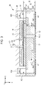
- FIG. 3 is a cross-sectional view taken along line III-III in FIG. 2
- FIG. 4 is a cross-sectional view taken along line IV-IV in FIG. 2
- FIG. 3 is a cross-sectional view of elements related to a single nozzle N in the first line L 1
- FIG. 4 is a cross-sectional view of elements related to a single nozzle N in the second line L 2 .
- the elements related to each nozzle N of the first line L 1 and the elements related to each nozzle N of the second line L 2 are in an inverted relationship with respect to a YZ plane.
- the liquid ejecting head 26 includes a flow path structure 30 .
- the flow path structure 30 forms flow paths that supply ink to the nozzles N.
- a diaphragm 42 , a protective substrate 46 , and a housing portion 48 are provided in a Z-axis negative direction with respect to the flow path structure 30 .
- a nozzle plate 62 and vibration absorbers 64 are provided in a Z-axis positive direction with respect to a flow path substrate 32 .
- each element of the liquid ejecting head 26 is a plate-shaped member elongated along the Y-axis and is joined to each other using an adhesive agent, for example.
- the nozzle plate 62 is a plate-shaped member in which a plurality of nozzles N are formed and is provided on a surface of the flow path structure 30 in the Z-axis positive direction . Each of the plurality of nozzles N is a circular through hole through which ink passes.
- the plurality of nozzles N constituting the first line L 1 and the plurality of nozzles N constituting the second line L 2 are formed.
- the nozzle plate 62 is manufactured by processing a single crystal substrate formed of silicon using a semiconductor manufacturing technique such as, for example, dry etching or wet etching. However, any known materials and any known manufacturing methods can be adopted to manufacture the nozzle plate 62 .
- the flow path structure 30 includes the flow path substrate 32 and a pressure chamber substrate 34 .
- the flow path substrate 32 is positioned in the Z-axis positive direction in the flow path structure 30
- the pressure chamber substrate 34 is positioned in the Z-axis negative direction in the flow path structure 30 .
- a space Ka 1 and a space Ka 2 are formed in the flow path substrate 32 .
- the space Ka 1 and the space Ka 2 are each an opening elongated along the Y-axis.
- the space Ka 1 is formed, in the flow path substrate 32 , in an X-axis positive direction
- the space Ka 2 is formed, in the flow path substrate 32 , in an X-axis negative direction.
- the flow path substrate 32 of the first embodiment is formed of layers including a first substrate 321 and a second substrate 322 .
- the first substrate 321 is positioned between the second substrate 322 and the pressure chamber substrate 34 .
- the space Ka 1 is formed across the first substrate 321 and the second substrate 322 .
- the space Ka 2 is formed across the first substrate 321 and the second substrate 322 .
- the housing portion 48 is a case for storing the ink.
- a space Kb 1 corresponding to the space Ka 1 and a space Kb 2 corresponding to the space Ka 2 are formed in the housing portion 48 .
- the space Ka 1 of the flow path structure 30 and the space Kb 1 of the housing portion 48 are in communication with each other and the space Ka 2 of the flow path structure 30 and space Kb 2 of the housing portion 48 are in communication with each other.
- the space formed by the space Ka 1 and the space Kb 1 functions as a first common liquid chamber K 1
- the space formed by the space Ka 2 and the space Kb 2 functions as a second common liquid chamber K 2 .
- the first common liquid chamber K 1 and the second common liquid chamber K 2 are each a space commonly formed across a plurality of nozzles N and each store ink supplied to the plurality of nozzles N.
- An introduction port 481 and a discharge port 482 are formed in the housing portion 48 .
- the ink is supplied to the first common liquid chamber K 1 through the introduction port 481 .
- the ink inside the second common liquid chamber K 2 is discharged through the discharge port 482 .
- the vibration absorbers 64 are flexible films constituting wall surfaces of the first common liquid chamber K 1 and the second common liquid chamber K 2 and absorb the pressure fluctuations of the ink inside the first common liquid chamber K 1 and the ink inside the second common liquid chamber K 2 .
- FIG. 5 is a schematic diagram of the flow paths formed in the liquid ejecting head 26 .
- an individual flow path Q is formed for each nozzle N in the flow path structure 30 .
- a plurality of individual flow paths Q are each formed for a corresponding one of a plurality of nozzles N.
- the nozzles N are formed in the nozzle plate 62 at portions where the wall surfaces of the individual flow paths Q are formed.
- each nozzle N is formed so as to branch off from the corresponding individual flow path Q.
- the first common liquid chamber K 1 and the second common liquid chamber K 2 are in communication with each other through the individual flow paths Q.
- the individual flow paths Q are formed so that the space Ka 1 of the first common liquid chamber K 1 and the space Ka 2 of the second common liquid chamber K 2 communicate with each other.
- the individual flow paths Q are flow paths formed from an inner wall surface of the first common liquid chamber K 1 to an inner wall surface of the second common liquid chamber K 2 .
- the individual flow paths Q corresponding to the nozzles N of the first line L 1 and the individual flow paths Q corresponding to the nozzles N of the second line L 2 are in an inverted relationship with respect to the YZ plane.
- an opening O 1 which is a first end portion of the individual flow path Q corresponding to the nozzle N of the first line L 1 , is formed in an upper surface in inner wall surfaces of the space Ka 1
- an opening O 2 that is a second end portion is formed in a lateral surface in inner wall surfaces of the space Ka 2 .
- the opening O 1 is an interface between the individual flow path Q corresponding to the nozzle N of the first line L 1 and the inner wall surface of the space Ka 1
- the opening O 2 is an interface between the individual flow path Q corresponding to the nozzle N of the first line L 1 and the inner wall surface of the space Ka 2 .
- an opening O 3 which is a first end portion of the individual flow path Q corresponding to the nozzle N of the second line L 2 , is formed in a lateral surface in inner wall surfaces of the space Ka 2
- an opening O 4 that is a second end portion is formed in a lateral surface in inner wall surfaces of the space Ka 1 .
- the opening O 4 is an interface between the individual flow path Q corresponding to the nozzle N of the second line L 2 and the inner wall surface of the space Ka 1
- the opening O 3 is an interface between the individual flow path Q corresponding to the nozzle N of the second line L 2 and the inner wall surface of the space Ka 2 .
- the plurality of individual flow paths Q are arranged in parallel to each other along the Y-axis. In other words, a row of individual flow paths that includes the plurality of individual flow paths Q are formed. Specifically, the individual flow paths Q corresponding to the nozzles N of the first line L 1 and the individual flow paths Q corresponding to the nozzles N of the second line L 2 are arranged alternately in the Y-axis direction. As understood from the description above, the plurality of individual flow paths Q are in communication with both the first common liquid chamber K 1 and the second common liquid chamber K 2 . In the ink that is supplied to the individual flow paths Q from the first common liquid chamber K 1 , the ink that is not ejected through the nozzles N is stored in the second common liquid chamber K 2 .
- the liquid ejecting apparatus 100 includes a circulation mechanism 90 .
- the circulation mechanism 90 is a mechanism that recirculates the ink, which is to be discharged from the liquid ejecting head 26 , to the liquid ejecting head 26 .
- the circulation mechanism 90 is a mechanism that circulates the ink that is supplied to the liquid ejecting head 26 and includes, for example, a supply flow path 91 , a discharge flow path 92 , and a circulation pump 93 .
- the supply flow path 91 is a flow path that supplies the ink to the first common liquid chamber K 1 and is coupled to the introduction port 481 of the first common liquid chamber K 1 .
- the discharge flow path 92 is a flow path that discharges the ink from the second common liquid chamber K 2 and is coupled to the discharge port 482 of the second common liquid chamber K 2 .
- the circulation pump 93 is a pumping mechanism that sends the ink supplied through the discharge flow path 92 to the supply flow path 91 . In other words, the ink discharged from the second common liquid chamber K 2 is recirculated to the first common liquid chamber K 1 through the discharge flow path 92 , the circulation pump 93 , and the supply flow path 91 .
- the circulation mechanism 90 functions as an element that collects the ink from the second common liquid chamber K 2 and that recirculates the collected ink to the first common liquid chamber K 1 .
- a configuration in which the circulation mechanism 90 collects the ink from the first common liquid chamber K 1 and that recirculates the ink to the second common liquid chamber K 2 may be adopted as well.
- each individual flow path Q includes a pressure chamber C.
- the pressure chambers C are formed in the pressure chamber substrate 34 .
- the pressure chamber substrate 34 is a plate-shaped member in which the plurality of pressure chambers C are each formed for a corresponding one of the plurality of nozzles N.
- Each pressure chamber C is a space elongated along the X-axis in plan view.
- the plurality of pressure chambers C corresponding to the nozzles N of the first line L 1 are arranged in the Y-axis direction and in a portion in the pressure chamber substrate 34 in the X-axis positive direction.
- FIG. 1 illustrates the plurality of pressure chambers C corresponding to the nozzles N of the first line L 1 are arranged in the Y-axis direction and in a portion in the pressure chamber substrate 34 in the X-axis positive direction.
- the plurality of pressure chambers C corresponding to the nozzles N of the second line L 2 are arranged in the Y-axis direction and in a portion in the pressure chamber substrate 34 in the X-axis negative direction. Each pressure chamber C overlaps the corresponding nozzle N in plan view.
- the flow path substrate 32 and the pressure chamber substrate 34 are manufactured by processing a single crystal substrate formed of silicon using a semiconductor manufacturing technique, for example.
- a semiconductor manufacturing technique for example.
- any known materials and any known manufacturing methods can be adopted to manufacture the flow path substrate 32 and the pressure chamber substrate 34 .
- the diaphragm 42 is formed on a surface of the pressure chamber substrate 34 on a side opposite the flow path substrate 32 .
- the diaphragm 42 of the first embodiment is a plate-shaped member configured to vibrate elastically. Note that portions or the entire diaphragm 42 can be formed so as to be integrated with the pressure chamber substrate 34 by selectively removing portions of a plate-shaped member, having a predetermined plate thickness, corresponding to the pressure chambers C in the plate thickness direction.
- the pressure chambers C are spaces located between the flow path substrate 32 and the diaphragm 42 .
- energy generating portions 44 are formed on a surface of the diaphragm 42 on a side opposite the pressure chambers C.
- the energy generating portions 44 are each formed for a corresponding nozzle N.
- the plurality of energy generating portions 44 are each formed for a corresponding one of the plurality of nozzles N.
- Each energy generating portion 44 generates energy for ejecting ink.
- the energy generating portions 44 are each a drive element that ejects ink through the corresponding nozzle N by changing the pressure inside the corresponding pressure chamber C.
- piezoelectric elements are used as the energy generating portions 44 .
- each energy generating portion 44 generates a pressure for ejecting ink.
- each energy generating portion 44 is an actuator that becomes deformed by having a drive signal supplied thereto and is formed so as to be elongated along the X-axis in plan view.
- the plurality of energy generating portions 44 are arranged in the Y-axis direction so as to correspond to the plurality of pressure chambers C.
- the protective substrate 46 in FIG. 2 is a plate-shaped member that, while protecting the plurality of energy generating portions 44 , reinforces the mechanical strength of the diaphragm 42 . Interposing the diaphragm 42 with the pressure chamber substrate 34 , the protective substrate 46 is mounted on a side opposite the pressure chamber substrate 34 . The plurality of energy generating portions 44 are mounted between the protective substrate 46 and the diaphragm 42 .
- the protective substrate 46 is formed of silicon (Si), for example.
- a wiring substrate 50 for example, is joined to a surface of the diaphragm 42 .
- the wiring substrate 50 is a mounted component in which a plurality of wires that electrically couple the control unit 20 or a power supply circuit and the liquid ejecting head 26 to each other are formed.
- the flexible wiring substrate 50 such as, for example, a flexible printed circuit (FPC) or a flexible flat cable (FFC) is desirably used.
- a drive circuit 52 mounted on the wiring substrate 50 supplies a drive signal to each energy generating portion 44 .
- FIG. 6 is a schematic diagram focusing on, in the row of individual flow paths, two individual flow paths Q adjacent to each other in the Y-axis direction.
- the two individual flow paths Q one is denoted as a “first individual flow path Q 1 ” and the other is denoted as a “second individual flow path Q 2 ”.
- FIG. 7 is a cross-sectional view of the first individual flow path Q 1 and FIG. 8 is a cross-sectional view of the second individual flow path Q 2 .
- FIG. 7 is an enlarged view of the individual flow path Q illustrated as an example in FIG. 3 and FIG. 8 is an enlarged view of the individual flow path Q illustrated as an example in FIG. 4 .
- the first individual flow path Q 1 is an individual flow path Q corresponding to any single nozzle N (hereinafter, referred to as a “first nozzle N 1 ”) in the first line L 1
- the second individual flow path Q 2 is an individual flow path Q corresponding to any single nozzle N (hereinafter, referred to as a “second nozzle N 2 ”) in the second line L 2
- the first nozzle N 1 and the second nozzle N 2 are, among the plurality of nozzles N formed in the nozzle plate 62 , two nozzles N adjacent to each other when viewed in the X-axis direction.
- the pressure chamber C corresponding to the first individual flow path Q 1 is denoted as a “first pressure chamber C 1 ”
- the pressure chamber C corresponding to the second individual flow path Q 2 is denoted as a “second pressure chamber C 2 ”.
- the first individual flow path Q 1 and the second individual flow path Q 2 are in an inverted relationship with respect to an XZ plane. As illustrated as an example in FIGS. 6 and 7 , the first individual flow path Q 1 includes a first communication flow path Q 11 and a second communication flow path Q 12 .
- the first communication flow path Q 11 communicates the first common liquid chamber K 1 and the first nozzle N 1 with each other.
- the first communication flow path Q 11 is a flow path that extends from the opening O 1 formed in the upper surface of the space Ka 1 to an opening of the first nozzle N 1 in the Z-axis negative direction.
- the first communication flow path Q 11 of the first embodiment includes a first flow path 111 , the first pressure chamber C 1 , and a second flow path 112 .
- the first flow path 111 communicates the space Ka 1 and the first pressure chamber C 1 with each other.
- the first flow path 111 is a through hole formed along the Z-axis in the first substrate 321 .
- the first pressure chamber C 1 communicates the first flow path 111 and the second flow path 112 with each other.
- the first pressure chamber C 1 is a space that is elongated along the X-axis and that is formed in the pressure chamber substrate 34 .
- the energy generating portion 44 corresponding to the first nozzle N 1 is mounted on a surface of the diaphragm 42 on a side opposite the first pressure chamber C 1 . It can also be said that the energy generating portion 44 corresponding to the first nozzle N 1 is provided midway of the first individual flow path Q 1 . Note that the energy generating portion 44 corresponding to the first nozzle N 1 is an example of a “first energy generating portion”.
- the second flow path 112 communicates the first pressure chamber C 1 and the first nozzle N 1 with each other. Specifically, the second flow path 112 is a through hole formed along the Z-axis and across the first substrate 321 and the second substrate 322 .
- the first pressure chamber C 1 is in communication with the first common liquid chamber K 1 through the first flow path 111 and is in communication with the first nozzle N 1 through the second flow path 112 . Accordingly, the ink filled in the first pressure chamber C 1 from the first common liquid chamber K 1 through the first flow path 111 passes through the second flow path 112 and is ejected through the first nozzle N 1 with the deformation of the energy generating portion 44 corresponding to the first pressure chamber C 1 .
- the second communication flow path Q 12 communicates the second common liquid chamber K 2 and the first nozzle N 1 with each other.
- the second communication flow path Q 12 is a flow path that extends from a plane that includes a central axis of the first nozzle N 1 and that is parallel to the YZ plane to the opening O 2 formed in a lateral surface of the space Ka 2 .
- the second communication flow path Q 12 of the first embodiment includes a third flow path 121 , a fourth flow path 122 , and a fifth flow path 123 .
- the third flow path 121 communicates the first nozzle N 1 and the fourth flow path 122 with each other.
- the third flow path 121 is formed along the X-axis and in a surface of the second substrate 322 in the Z-axis positive direction.
- the fourth flow path 122 communicates the third flow path 121 and the fifth flow path 123 with each other.
- the fourth flow path 122 is a through hole formed along the Z-axis in the second substrate 322 .
- the fifth flow path 123 communicates the fourth flow path 122 and the second common liquid chamber K 2 with each other.
- the fifth flow path 123 is formed along the X-axis and in a surface of the second substrate 322 in the Z-axis negative direction.
- the second individual flow path Q 2 includes a third communication flow path Q 23 and a fourth communication flow path Q 24 .
- the third communication flow path Q 23 corresponds to the first communication flow path Q 11
- the fourth communication flow path Q 24 corresponds to the second communication flow path Q 12 .
- the first communication flow path Q 11 and the fourth communication flow path Q 24 are, in the X-axis positive direction, provided alternately along the Y-axis.
- the second communication flow path Q 12 and the third communication flow path Q 23 are, in the X-axis negative direction, provided alternately along the Y-axis.
- the fourth communication flow path Q 24 communicates the first common liquid chamber K 1 and the second nozzle N 2 with each other.
- the fourth communication flow path Q 24 is a flow path that extends from the opening O 4 formed in a lateral surface of the space Ka 1 to a plane that includes a central axis of the second nozzle N 2 and that is parallel to the YZ plane.
- the fourth communication flow path Q 24 of the first embodiment includes a sixth flow path 241 , a seventh flow path 242 , and an eighth flow path 243 .
- the sixth flow path 241 couples the first common liquid chamber K 1 and the seventh flow path 242 to each other.
- the sixth flow path 241 is formed along the X-axis and in a surface of the second substrate 322 in the Z-axis negative direction.
- the seventh flow path 242 couples the sixth flow path 241 and the eighth flow path 243 to each other.
- the seventh flow path 242 is a through hole formed along the Z-axis in the second substrate 322 .
- the eighth flow path 243 communicates the seventh flow path 242 and the second nozzle N 2 with each other.
- the eighth flow path 243 is formed along the X-axis and in a surface of the second substrate 322 in the Z-axis positive direction.
- the third communication flow path Q 23 is a flow path that communicates the second common liquid chamber K 2 and the second nozzle N 2 with each other. Specifically, the third communication flow path Q 23 is a flow path that extends from an opening of the second nozzle N 2 in the Z-axis negative direction to the opening O 3 formed in an upper surface of the space Ka 2 .
- the third communication flow path Q 23 of the first embodiment includes a ninth flow path 231 , the second pressure chamber C 2 , and a tenth flow path 232 .
- the ninth flow path 231 couples the second nozzle N 2 and the second pressure chamber C 2 to each other. Specifically, the ninth flow path 231 is a through hole formed along the Z-axis and across the first substrate 321 and the second substrate 322 .
- the second pressure chamber C 2 communicates the ninth flow path 231 and the tenth flow path 232 with each other.
- the second pressure chamber C 2 is a space that is elongated along the X-axis and that is formed in the pressure chamber substrate 34 .
- the energy generating portion 44 corresponding to the second nozzle N 2 is mounted on a surface of the diaphragm 42 on a side opposite the second pressure chamber C 2 . It can also be said that the energy generating portion 44 corresponding to the second nozzle N 2 is provided midway of the second individual flow path Q 2 . Note that the energy generating portion 44 corresponding to the second nozzle N 2 is an example of a “second energy generating portion”.
- the tenth flow path 232 communicates the second pressure chamber C 2 and the space Ka 2 with each other. Specifically, the tenth flow path 232 is a through hole formed along the Z-axis in the first substrate 321 .
- the ink is filled into the second pressure chamber C 2 from the first common liquid chamber K 1 through the fourth communication flow path Q 24 and the ninth flow path 231 .
- the ink inside the second pressure chamber C 2 is ejected through the second nozzle N 2 via the ninth flow path 231 with the deformation of the energy generating portion 44 .
- the ink that is supplied to the second individual flow path Q 2 from the first common liquid chamber K 1 the ink that is not ejected through the second nozzle N 2 is stored in the second common liquid chamber K 2 .
- a flow path resistance R of the first individual flow path Q 1 and a flow path resistance R of the second individual flow path Q 2 are the same.
- a flow path resistance R is a total value of a flow path resistance R of the first communication flow path Q 11 and a flow path resistance R of the second communication flow path Q 12 .
- a flow path resistance R of the second individual flow path Q 2 is a total value of a flow path resistance R of the third communication flow path Q 23 and a flow path resistance R of the fourth communication flow path Q 24 .
- the flow path resistance R is, for example, calculated with the Expression (1) below, where ⁇ is a viscosity of the ink, L is a flow path length, and d is a flow path diameter.
- the flow path diameter d is a diameter of a circle in which the area is the same as the cross-sectional area of the flow path.
- the total value of the flow path resistance R of each section is the flow path resistance R of the flow path.
- the flow path resistance R can be set by adjusting the flow path length L and the flow path diameter d.
- the ejection characteristics are, for example, the ejecting amount, the ejecting direction, and the ejecting speed.
- the flow path resistance R of the first communication flow path Q 11 and the flow path resistance R of the fourth communication flow path Q 24 are the same. Accordingly, an error between a pressure loss occurring in the flow of the ink from the first common liquid chamber K 1 , via the first communication flow path Q 11 , to the first nozzle N 1 and a pressure loss occurring in the flow of the ink from the first common liquid chamber K 1 , via the fourth communication flow path Q 24 , to the second nozzle N 2 can be reduced. In other words, an error in the ejection characteristics between the first nozzle N 1 and the second nozzle N 2 can be reduced.
- the flow path resistance R of the first communication flow path Q 11 is a total value of a flow path resistance R of the first flow path 111 , a flow path resistance R of the first pressure chamber C 1 , and a flow path resistance R of the second flow path 112 .
- the flow path resistance R of the fourth communication flow path Q 24 is a total value of a flow path resistance R of the sixth flow path 241 , a flow path resistance R of the seventh flow path 242 , and a flow path resistance R of the eighth flow path 243 .
- the flow path resistance R of the second communication flow path Q 12 and the flow path resistance R of the third communication flow path Q 23 are the same. Accordingly, an error between a pressure loss occurring in the flow of the ink from the first nozzle N 1 , via the second communication flow path Q 12 , to the second common liquid chamber K 2 and a pressure loss occurring in the flow of the ink from the second nozzle N 2 , via the third communication flow path Q 23 , to the second common liquid chamber K 2 can be reduced. In other words, an error in the ejection characteristics between the first nozzle N 1 and the second nozzle N 2 can be reduced.
- the flow path resistance R of the second communication flow path Q 12 is a total value of a flow path resistance R of the third flow path 121 , a flow path resistance R of the fourth flow path 122 , and a flow path resistance R of the fifth flow path 123 .
- the flow path resistance R of the third communication flow path Q 23 is a total value of a flow path resistance R of the ninth flow path 231 , a flow path resistance R of the second pressure chamber C 2 , and a flow path resistance R of the tenth flow path 232 .
- the ink can be supplied to the first nozzle N 1 from the second common liquid chamber K 2 as well.
- the flow path resistance R of the first communication flow path Q 11 and the flow path resistance R of the second communication flow path Q 12 are equalized.
- the flow path resistance R of the first common liquid chamber K 1 side and that of the second common liquid chamber K 2 side are the same. Accordingly, occurrence of errors in the ejection characteristics of the first nozzle N 1 between when the ink is supplied to the first nozzle N 1 from the first common liquid chamber K 1 and when the ink is supplied to the first nozzle N 1 from the second common liquid chamber K 2 can be reduced.
- the flow path resistance R of the third communication flow path Q 23 and the flow path resistance R of the fourth communication flow path Q 24 are equalized.
- the flow path resistance R of the first common liquid chamber K 1 side and that of the second common liquid chamber K 2 side are the same. Accordingly, occurrence of errors in the ejection characteristics of the second nozzle N 2 between when the ink is supplied to the second nozzle N 2 from the first common liquid chamber K 1 and when the ink is supplied to the second nozzle N 2 from the second common liquid chamber K 2 can be reduced.
- a flow path resistance Ra of a flow path A and a flow path resistance Rb of a flow path B are the same includes, other than a case in which the flow path resistance Ra and the flow path resistance Rb are strictly the same, a case in which the flow path resistance Ra and the flow path resistance Rb are practically the same.
- “the flow path resistance Ra and the flow path resistance Rb are practically the same” is when the flow path resistance Ra and the flow path resistance Rb are, with respect to each other, within the range of the manufacturing error.
- the flow path resistance Ra and the flow path resistance Rb satisfy the following Expression (2), it can be said that “the flow path resistance Ra and the flow path resistance Rb are practically the same”. 0.45 ⁇ Ra /( Ra+Rb ) ⁇ 0.55 (2)
- the flow path resistance R of the first communication flow path Q 11 and the flow path resistance R of the second communication flow path Q 12 are practically the same” means that, with respect to half the value of the flow path resistance R of the entire first individual flow path Q 1 , the first communication flow path Q 11 and the second communication flow path Q 12 are formed, with the first nozzle N 1 as the reference, so that the deviation in the flow path resistances R is within ⁇ 5%.
- the relationships between the flow path resistances R of the other flow paths are similar to the above relationship.
- an inertance M of the first communication flow path Q 11 in the first individual flow path Q 1 is set smaller than an inertance M of the second communication flow path Q 12 in the first individual flow path Q 1 .
- the inertance M can be set by adjusting the flow path length L and the flow-path sectional area S. Pressure oscillation generated in the first pressure chamber C 1 with the energy generating portion 44 creates a flow of the ink in the first communication flow path Q 11 towards the first nozzle N 1 . A portion of the ink in the first communication flow path Q 11 flowing towards the first nozzle N 1 is ejected through the first nozzle N 1 , and the remaining ink is discharged to the second common liquid chamber K 2 through the second communication flow path Q 12 .
- a configuration in which the amount of ink discharged through the second communication flow path Q 12 is set relatively small and in which the amount of ink ejected through the first nozzle N 1 is set relatively large is desirable.
- a design in which the inertance M of the second communication flow path Q 12 is large is effective.
- the inertance M of the second communication flow path Q 12 is set larger than the inertance M of the first communication flow path Q 11 .
- a design in which the inertance M of the first communication flow path Q 11 is smaller than the inertance M of the second communication flow path Q 12 is adopted.
- the inertance M can be adjusted with the flow path length L. Specifically, the flow path length L and the inertance M are in a proportional relation. Accordingly, the inertance M of the first communication flow path Q 11 is set smaller than the inertance M of the second communication flow path Q 12 by having a flow path length L of the first communication flow path Q 11 be shorter than a flow path length L of the second communication flow path Q 12 .
- the flow path length L of the first communication flow path Q 11 is, for example, a distance along a center line of the first communication flow path Q 11 from an end point of the first communication flow path Q 11 on the first common liquid chamber K 1 side to an end point of the first communication flow path Q 11 on the first nozzle N 1 side.
- the end point of the first communication flow path Q 11 on the first common liquid chamber K 1 side is an intersection between the opening O 1 and the center line of the first communication flow path Q 11 .
- the end point of the first communication flow path Q 11 on the first nozzle N 1 side is an intersection between the center line of the first communication flow path Q 11 and an opening of the first nozzle N 1 in the Z-axis negative direction.
- the flow path length L of the second communication flow path Q 12 is, for example, a distance along a center line of the second communication flow path Q 12 from an end point of the second communication flow path Q 12 on the first nozzle N 1 side to an end point of the second communication flow path Q 12 on the second common liquid chamber K 2 side.
- the end point of the second communication flow path Q 12 on the first nozzle N 1 side is an intersection between the center line of the second communication flow path Q 12 and a plane that includes the central axis of the first nozzle N 1 and that is parallel to the YZ plane.
- the end point of the second communication flow path Q 12 on the second common liquid chamber K 2 side is an intersection between the opening O 2 and the center line of the second communication flow path Q 12 .
- the inertance M of the first communication flow path Q 11 and the inertance M of the second communication flow path Q 12 are adjusted by differing the flow path diameter d of the first communication flow path Q 11 and the flow path diameter d of the second communication flow path Q 12 , as it can be understood from Expression (1), the effect on the flow path resistance R is large.
- the inertance M of the first communication flow path Q 11 can be set smaller than the inertance M of the second communication flow path Q 12 while suppressing the effect on the flow path resistance R.
- a configuration in which the flow path diameter d of the first communication flow path Q 11 and the flow path diameter d of the second communication flow path Q 12 are differed can be adopted as well.
- a minimum diameter of the first communication flow path Q 11 is smaller than a minimum diameter of the second communication flow path Q 12 .
- the minimum diameter is the smallest value of the flow path diameter.
- the minimum diameter of the first communication flow path Q 11 is, for example, a flow path diameter of the first flow path 111 .
- the minimum diameter of the second communication flow path Q 12 is, for example, a flow path diameter of the fifth flow path 123 . Note that it can also be said that a minimum flow-path sectional area of the first communication flow path Q 11 is smaller than a minimum flow-path sectional area of the second communication flow path Q 12 .
- the minimum diameter of the second communication flow path Q 12 is set larger than the minimum diameter of the first communication flow path Q 11 .
- the minimum diameter of the first communication flow path Q 11 is set smaller than the minimum diameter of the second communication flow path Q 12 .
- a configuration in which the minimum diameter of the first communication flow path Q 11 is larger than the minimum diameter of the second communication flow path Q 12 can be adopted as well.
- Pressure oscillation generated in the second pressure chamber C 2 with the energy generating portion 44 creates a flow of the ink in the third communication flow path Q 23 towards the second nozzle N 2 .
- a portion of the ink in the third communication flow path Q 23 flowing towards the second nozzle N 2 is ejected through the second nozzle N 2 , and the remaining ink flows to the fourth communication flow path Q 24 side.
- a configuration in which the amount of ink flowing to the fourth communication flow path Q 24 side is set relatively small and in which the amount of ink ejected through the second nozzle N 2 is set relatively large is desirable.
- a design in which the inertance M of the fourth communication flow path Q 24 is large is effective.
- the inertance M of the fourth communication flow path Q 24 is set larger than the inertance M of the third communication flow path Q 23 .
- a design in which the inertance M of the third communication flow path Q 23 is smaller than the inertance M of the fourth communication flow path Q 24 is adopted.
- the inertance M of the third communication flow path Q 23 is set smaller than the inertance M of the fourth communication flow path Q 24 by having a flow path length L of the third communication flow path Q 23 be shorter than a flow path length L of the fourth communication flow path Q 24 .
- the flow path length L of the third communication flow path Q 23 is, for example, a distance along a center line of the third communication flow path Q 23 from an end point of the third communication flow path Q 23 on the second nozzle N 2 side to an end point of the third communication flow path Q 23 on the second common liquid chamber K 2 side.
- the end point of the third communication flow path Q 23 on the second nozzle N 2 side is an intersection between the center line of the third communication flow path Q 23 and an opening of the second nozzle N 2 in the Z-axis negative direction.
- the end point of the third communication flow path Q 23 on the second common liquid chamber K 2 side is an intersection between the opening O 3 and the center line of the third communication flow path Q 23 .
- the flow path length L of the fourth communication flow path Q 24 is, for example, a distance along a center line of the fourth communication flow path Q 24 from an end point of the fourth communication flow path Q 24 on the first common liquid chamber K 1 side to an end point of the fourth communication flow path Q 24 on the second nozzle N 2 side.
- the end point of the fourth communication flow path Q 24 on the first common liquid chamber K 1 side is an intersection between the opening O 4 and the center line of the fourth communication flow path Q 24 .
- the end point of the fourth communication flow path Q 24 on the second nozzle N 2 side is an intersection between the center line of the fourth communication flow path Q 24 and a plane that includes the central axis of the second nozzle N 2 and that is parallel to the YZ plane.
- the inertance M of the third communication flow path Q 23 and the inertance M of the fourth communication flow path Q 24 are adjusted by differing the flow path diameter d of the third communication flow path Q 23 and the flow path diameter d of the fourth communication flow path Q 24 , as described above, the effect on the flow path resistance R is large.
- the inertance M of the third communication flow path Q 23 can be set smaller than the inertance M of the fourth communication flow path Q 24 while suppressing the effect on the flow path resistance R.
- a configuration in which the flow path diameter d of the third communication flow path Q 23 and the flow path diameter d of the fourth communication flow path Q 24 are differed can be adopted as well.
- a minimum diameter of the third communication flow path Q 23 is smaller than a minimum diameter of the fourth communication flow path Q 24 .
- the minimum diameter of the third communication flow path Q 23 is, for example, a flow path diameter of the tenth flow path 232 .
- the minimum diameter of the fourth communication flow path Q 24 is, for example, a minimum diameter of the sixth flow path 241 . Note that it can also be said that a minimum flow-path sectional area of the third communication flow path Q 23 is smaller than a minimum flow-path sectional area of the fourth communication flow path Q 24 . In a flow path that has been relatively narrowed as in the sixth flow path 241 , compared with the addition of the inertance M, a larger resistance is added to the flow path.
- the inertance M of the fourth communication flow path Q 24 becomes relatively small, which causes the ejection efficiency to decrease. Accordingly, in the first embodiment, the minimum diameter of the fourth communication flow path Q 24 is set larger than the minimum diameter of the third communication flow path Q 23 .
- the minimum diameter of the third communication flow path Q 23 is set smaller than the minimum diameter of the fourth communication flow path Q 24 .
- a configuration in which the minimum diameter of the third communication flow path Q 23 is larger than the minimum diameter of the fourth communication flow path Q 24 can be adopted as well.
- a configuration (hereinafter, referred to as a “comparative example”) in which the row of individual flow paths is formed with only the first individual flow paths Q 1 is assumed.
- a plurality of first communication flow paths Q 11 are arranged in the flow path structure 30 in the X-axis positive direction
- a plurality of second communication flow paths Q 12 that each have an inertance M that is larger than that of the first communication flow path Q 11 are arranged in the flow path structure 30 in the X-axis negative direction.
- large inertances M and small inertances M are unevenly distributed in the flow path structure 30 .
- the inertance M depends on the flow path length or the flow path diameter. Accordingly, in the comparative example, the flow paths cannot be disposed efficiently. In other words, there will be wasted spaces in the flow path structure 30 .
- the first communication flow path Q 11 , and the fourth communication flow path Q 24 that has the inertance M that is larger than that of the first communication flow path Q 11 are positioned alternately in the Y-axis direction.
- the third communication flow path Q 23 , and the second communication flow path Q 12 that has the inertance M that is larger than that of the third communication flow path Q 23 are positioned alternately in the Y-axis direction.
- large inertances M and small inertances M are evenly distributed in the flow path structure 30 .
- FIG. 9 is a cross-sectional view of the first individual flow path Q 1 according to the second embodiment
- FIG. 10 is a cross-sectional view of the second individual flow path Q 2 according to the second embodiment.
- the structures of the first individual flow path Q 1 and the second individual flow path Q 2 of the second embodiment are similar to those of the first embodiment.
- the positions of the first nozzles N 1 and the second nozzles N 2 are different from those of the first embodiment.
- the first individual flow path Q 1 and the second individual flow path Q 2 are in an inverted relationship with respect to the YZ plane.
- the flow path resistances R of the flow paths are similar to those of the first embodiment.
- the first individual flow path Q 1 and the second individual flow path Q 2 include a flow path (hereinafter, referred to as a “local flow path”) Qa that extends in the X-axis direction.
- the local flow path Qa is formed in a surface of the second substrate 322 in the Z-axis positive direction.
- the first nozzle N 1 and the second nozzle N 2 are each formed in an area (hereinafter, referred to as a “local area”) in the nozzle plate 62 corresponding to the local flow path Qa. It can also be said the local area constitutes a bottom surface of the local flow path Qa.
- each of the first nozzle N 1 and the second nozzle N 2 is formed so as to branch off from the corresponding local flow path Qa.
- the first nozzle N 1 is, in cross-sectional view, formed in an area of the local area in the X-axis positive direction, for example.
- the second nozzle N 2 is, in cross-sectional view, formed in an area of the local area in the X-axis negative direction, for example.
- the first communication flow path Q 11 communicates the first common liquid chamber K 1 and the first nozzle N 1 with each other.
- the first communication flow path Q 11 of the second embodiment is a flow path that extends from the opening O 1 formed in the upper surface of the space Ka 1 to a plane that includes the central axis of the first nozzle N 1 and that is parallel to the YZ plane.
- the flow path length L of the first communication flow path Q 11 is a distance along the center line of the first communication flow path Q 11 from the end point of the communication flow path Q 11 on the first common liquid chamber K 1 side to an end point of the first communication flow path Q 11 on the first nozzle N 1 side.
- the end point of the first communication flow path Q 11 on the first common liquid chamber K 1 side is the intersection between the center line of the first communication flow path Q 11 and the opening O 1 .
- the end point of the first communication flow path Q 11 on the first nozzle N 1 side is an intersection between the center line of the first communication flow path Q 11 and the plane that includes the central axis of the first nozzle N 1 and that is parallel to the YZ plane.
- the second communication flow path Q 12 communicates the second common liquid chamber K 2 and the first nozzle N 1 with each other.
- the second communication flow path Q 12 of the second embodiment is a flow path that extends from the plane that includes the central axis of the first nozzle N 1 and that is parallel to the YZ plane to the opening O 2 formed in the lateral surface of the space Ka 2 .
- the flow path length of the second communication flow path Q 12 is, similar to the first embodiment, a distance along the center line of the second communication flow path Q 12 from an end point of the second communication flow path Q 12 on the first nozzle N 1 side to the end point of the second communication flow path Q 12 on the second common liquid chamber K 2 side.
- the end point of the second communication flow path Q 12 on the first nozzle N 1 side is an intersection between the center line of the second communication flow path Q 12 and the plane that includes the central axis of the first nozzle N 1 and that is parallel to the YZ plane.
- the end point of the second communication flow path Q 12 on the second common liquid chamber K 2 side is, similar to the first embodiment, the intersection between the opening O 2 and the center line of the second communication flow path Q 12 .
- the inertance M of the first communication flow path Q 11 is smaller than the inertance M of the second communication flow path Q 12
- the flow path length of the first communication flow path Q 11 is shorter than the flow path length of the second communication flow path Q 12 .
- the fourth communication flow path Q 24 communicates the first common liquid chamber K 1 and the second nozzle N 2 with each other.
- the fourth communication flow path Q 24 of the second embodiment is a flow path that extends from the opening O 4 formed in the space Ka 1 to a plane that includes a central axis of the second nozzle N 2 and that is parallel to the YZ plane.
- the flow path length L of the fourth communication flow path Q 24 is a distance along the center line of the fourth communication flow path Q 24 from the end point of the fourth communication flow path Q 24 on the first common liquid chamber K 1 side to an end point of the fourth communication flow path Q 24 on the second nozzle N 2 side.
- the end point of the fourth communication flow path Q 24 on the first common liquid chamber K 1 side is, similar to the first embodiment, the intersection between the opening O 4 and the center line of the fourth communication flow path Q 24 .
- the end point of the fourth communication flow path Q 24 on the second nozzle N 2 side is an intersection between the center line of the fourth communication flow path Q 24 and a plane that includes the central axis of the second nozzle N 2 and that is parallel to the YZ plane.
- the third communication flow path Q 23 communicates the second common liquid chamber K 2 and the second nozzle N 2 with each other.
- the third communication flow path Q 23 of the second embodiment is a flow path that extends from the plane that includes the central axis of the second nozzle N 2 and that is parallel to the YZ plane to the opening O 3 formed in the upper surface of the space Ka 2 .
- the flow path length L of the third communication flow path Q 23 is a distance along the center line of the third communication flow path Q 23 from the end point of the third communication flow path Q 23 on the second nozzle N 2 side to an end point of the third communication flow path Q 23 on the second common liquid chamber K 2 side.
- the end point of the third communication flow path Q 23 on the second nozzle N 2 side is an intersection between the center line of the third communication flow path Q 23 and the plane that includes the central axis of the second nozzle N 2 and that is parallel to the YZ plane.
- the end point of the third communication flow path Q 23 on the second common liquid chamber K 2 side is, similar to the first embodiment, the intersection between the opening O 3 and the center line of the third communication flow path Q 23 .
- the inertance M of the third communication flow path Q 23 is smaller than the inertance M of the fourth communication flow path Q 24
- the flow path length of the third communication flow path Q 23 is shorter than the flow path length of the fourth communication flow path Q 24 .
- the positions of the first nozzle N 1 and the second nozzle N 2 are optional in a configuration in which the inertance M of the first communication flow path Q 11 is smaller than the inertance M of the second communication flow path Q 12 and in which the inertance M of the third communication flow path Q 23 is smaller than the inertance M of the fourth communication flow path Q 24 .
- the position of the first nozzle N 1 in the X-axis direction and the position of the second nozzle N 2 in the X-axis direction may be the same.
- the shapes of the individual flow paths Q are not limited to those illustrated as examples in the configurations described above.
- the first communication flow path Q 11 may include another flow path.
- the second communication flow path Q 12 the third communication flow path Q 23 , and the fourth communication flow path Q 24 .
- the shapes of the first individual flow path Q 1 and the second individual flow path Q 2 may be different, or the shapes of the first individual flow path Q 1 and the second individual flow path Q 2 may be the same.
- the flow path substrate 32 is formed of layers including the first substrate 321 and the second substrate 322 ; however, the configuration of the flow path substrate 32 is not limited to the example described above.
- the flow path substrate 32 may be formed of a single layer, or the flow path substrate 32 may be formed of at least three layers.
- the flow path diameter of the first flow path 111 is the minimum diameter of the first communication flow path Q 11 ; however, the minimum diameter of the first flow path 111 may be a flow path diameter of a flow path other than the first flow path 111 .
- the minimum diameter of each of the second communication flow path Q 12 , the third communication flow path Q 23 , and the fourth communication flow path Q 24 may be a flow path diameter of any flow path in the corresponding communication flow path.
- the energy generating portions 44 that generate energy to eject the liquid inside the pressure chambers C through the nozzles N are not limited to the piezoelectric elements.
- heating elements that generate air bubbles inside the pressure chambers C through heating to change the pressure inside the pressure chambers C may be used as the energy generating portions 44 .
- the energy generating portions 44 are expressed comprehensively as elements that eject the liquid in the pressure chambers C through the nozzles N, and the operation system such as a piezoelectric system or a thermal system, and the specific configuration of the energy generating portions 44 do not need to be stated in particular.
- the energy to eject the liquid includes both heat and pressure.
- the liquid ejecting apparatus 100 described as an example in the configurations described above may be employed in various apparatuses other than an apparatus dedicated to printing, such as a facsimile machine and a copier.
- the application of the liquid ejecting apparatus of the present disclosure is not limited to printing.
- a liquid ejecting apparatus that ejects a coloring material solution is used as a manufacturing apparatus that forms a color filter of a display device such as a liquid crystal display panel.
- a liquid ejecting apparatus that ejects a conductive material solution is used as a manufacturing apparatus that forms wiring and electrodes of a wiring substrate.
- a liquid ejecting apparatus that ejects a solution of an organic matter related to a living body is used, for example, as a manufacturing apparatus that manufactures a biochip.
Abstract
Description
R=128 μL/πd 4 (1)
0.45≤Ra/(Ra+Rb)≤0.55 (2)
M=ρL/S (3)
Claims (11)
Applications Claiming Priority (3)
| Application Number | Priority Date | Filing Date | Title |
|---|---|---|---|
| JP2019140487A JP7371381B2 (en) | 2019-07-31 | 2019-07-31 | Liquid ejection head and liquid ejection device |
| JPJP2019-140487 | 2019-07-31 | ||
| JP2019-140487 | 2019-07-31 |
Publications (2)
| Publication Number | Publication Date |
|---|---|
| US20210031517A1 US20210031517A1 (en) | 2021-02-04 |
| US11338583B2 true US11338583B2 (en) | 2022-05-24 |
Family
ID=71894637
Family Applications (1)
| Application Number | Title | Priority Date | Filing Date |
|---|---|---|---|
| US16/942,133 Active US11338583B2 (en) | 2019-07-31 | 2020-07-29 | Liquid ejecting head and liquid ejecting apparatus |
Country Status (4)
| Country | Link |
|---|---|
| US (1) | US11338583B2 (en) |
| EP (1) | EP3771566B1 (en) |
| JP (1) | JP7371381B2 (en) |
| CN (1) | CN112297624B (en) |
Cited By (1)
| Publication number | Priority date | Publication date | Assignee | Title |
|---|---|---|---|---|
| US20220363056A1 (en) * | 2021-05-14 | 2022-11-17 | Seiko Epson Corporation | Liquid ejecting head and liquid ejecting apparatus |
Families Citing this family (1)
| Publication number | Priority date | Publication date | Assignee | Title |
|---|---|---|---|---|
| JP2022071563A (en) * | 2020-10-28 | 2022-05-16 | ブラザー工業株式会社 | Liquid discharge head |
Citations (4)
| Publication number | Priority date | Publication date | Assignee | Title |
|---|---|---|---|---|
| WO1989002577A1 (en) | 1987-09-09 | 1989-03-23 | Spectra, Inc. | Ink jet array |
| US20130233939A1 (en) | 2012-03-07 | 2013-09-12 | Seiko Epson Corporation | Liquid ejecting head and liquid ejecting apparatus |
| US8851639B2 (en) * | 2012-02-14 | 2014-10-07 | Fujifilm Corporation | Liquid ejection apparatus |
| US20170239946A1 (en) | 2016-02-19 | 2017-08-24 | Canon Kabushiki Kaisha | Print element substrate and liquid ejection head |
Family Cites Families (10)
| Publication number | Priority date | Publication date | Assignee | Title |
|---|---|---|---|---|
| EP2296896B1 (en) | 2008-05-23 | 2022-05-18 | FUJIFILM Corporation | Fluid droplet ejecting |
| JP5209431B2 (en) * | 2008-09-30 | 2013-06-12 | 富士フイルム株式会社 | Inkjet recording device |
| JP2010214847A (en) * | 2009-03-18 | 2010-09-30 | Fujifilm Corp | Liquid droplet ejection head and image forming apparatus |
| JP5620726B2 (en) * | 2010-06-30 | 2014-11-05 | 富士フイルム株式会社 | Liquid discharge head and ink jet recording apparatus |
| JP5831081B2 (en) | 2011-09-16 | 2015-12-09 | 株式会社リコー | Liquid ejection head and image forming apparatus |
| JP6370084B2 (en) | 2014-04-10 | 2018-08-08 | 株式会社荏原製作所 | Substrate processing equipment |
| CN106660365B (en) * | 2014-06-27 | 2019-01-18 | 京瓷株式会社 | Channel member, fluid ejection head and recording device |
| JP6950210B2 (en) | 2017-03-15 | 2021-10-13 | ブラザー工業株式会社 | Liquid discharge head |
| JP6972605B2 (en) * | 2017-03-23 | 2021-11-24 | セイコーエプソン株式会社 | Liquid discharge head and liquid discharge device |
| JP2019140487A (en) | 2018-02-08 | 2019-08-22 | 日本電気株式会社 | Control device, relay device, communication system, and band control method |
-
2019
- 2019-07-31 JP JP2019140487A patent/JP7371381B2/en active Active
-
2020
- 2020-07-28 CN CN202010735706.8A patent/CN112297624B/en active Active
- 2020-07-29 US US16/942,133 patent/US11338583B2/en active Active
- 2020-07-30 EP EP20188538.1A patent/EP3771566B1/en active Active
Patent Citations (6)
| Publication number | Priority date | Publication date | Assignee | Title |
|---|---|---|---|---|
| WO1989002577A1 (en) | 1987-09-09 | 1989-03-23 | Spectra, Inc. | Ink jet array |
| JPH02500584A (en) | 1987-09-09 | 1990-03-01 | スペクトラ インコーポレーテッド | inkjet array |
| US8851639B2 (en) * | 2012-02-14 | 2014-10-07 | Fujifilm Corporation | Liquid ejection apparatus |
| US20130233939A1 (en) | 2012-03-07 | 2013-09-12 | Seiko Epson Corporation | Liquid ejecting head and liquid ejecting apparatus |
| JP2013184372A (en) | 2012-03-07 | 2013-09-19 | Seiko Epson Corp | Liquid ejecting head and liquid ejecting apparatus |
| US20170239946A1 (en) | 2016-02-19 | 2017-08-24 | Canon Kabushiki Kaisha | Print element substrate and liquid ejection head |
Cited By (2)
| Publication number | Priority date | Publication date | Assignee | Title |
|---|---|---|---|---|
| US20220363056A1 (en) * | 2021-05-14 | 2022-11-17 | Seiko Epson Corporation | Liquid ejecting head and liquid ejecting apparatus |
| US11840085B2 (en) * | 2021-05-14 | 2023-12-12 | Seiko Epson Corporation | Liquid ejecting head and liquid ejecting apparatus |
Also Published As
| Publication number | Publication date |
|---|---|
| EP3771566A1 (en) | 2021-02-03 |
| JP2021024080A (en) | 2021-02-22 |
| US20210031517A1 (en) | 2021-02-04 |
| JP7371381B2 (en) | 2023-10-31 |
| CN112297624A (en) | 2021-02-02 |
| CN112297624B (en) | 2023-08-08 |
| EP3771566B1 (en) | 2022-12-07 |
Similar Documents
| Publication | Publication Date | Title |
|---|---|---|
| US11338583B2 (en) | Liquid ejecting head and liquid ejecting apparatus | |
| US11618265B2 (en) | Liquid ejecting head and liquid ejecting apparatus | |
| US20200198349A1 (en) | Liquid ejecting head and liquid ejecting apparatus | |
| US11225072B2 (en) | Liquid ejecting head and liquid ejecting system | |
| JP7318399B2 (en) | Liquid ejection head and liquid ejection device | |
| US11660866B2 (en) | Liquid ejecting head and liquid ejecting apparatus | |
| US11548280B2 (en) | Liquid ejecting head and liquid ejecting system | |
| US10974509B2 (en) | Liquid ejecting head unit, liquid ejecting head module, and liquid ejecting apparatus | |
| EP3705296B1 (en) | Liquid ejecting head and liquid ejecting apparatus | |
| US11951740B2 (en) | Liquid ejecting head and liquid ejecting apparatus | |
| CN111347784B (en) | Liquid discharge head and liquid discharge apparatus | |
| JP7318398B2 (en) | Liquid ejection head and liquid ejection device | |
| US11491785B2 (en) | Liquid ejecting head and liquid ejecting system | |
| US11225073B2 (en) | Liquid ejecting head and liquid ejecting system | |
| US11878523B2 (en) | Liquid ejecting head and liquid ejecting apparatus | |
| JP7283116B2 (en) | Liquid ejection head and liquid ejection device | |
| US20230202185A1 (en) | Liquid Ejecting Head And Liquid Ejecting Apparatus | |
| US11554584B2 (en) | Liquid ejecting head and liquid ejecting apparatus | |
| US11577509B2 (en) | Liquid ejecting head and liquid ejecting apparatus | |
| JP7159847B2 (en) | Liquid ejection head and liquid ejection device | |
| US20230249463A1 (en) | Liquid ejecting head and liquid ejecting apparatus | |
| US20230249457A1 (en) | Liquid ejecting head and liquid ejecting apparatus |
Legal Events
| Date | Code | Title | Description |
|---|---|---|---|
| AS | Assignment |
Owner name: SEIKO EPSON CORPORATION, JAPAN Free format text: ASSIGNMENT OF ASSIGNORS INTEREST;ASSIGNOR:UCHIDA, KAZUAKI;REEL/FRAME:053344/0299 Effective date: 20200415 |
|
| FEPP | Fee payment procedure |
Free format text: ENTITY STATUS SET TO UNDISCOUNTED (ORIGINAL EVENT CODE: BIG.); ENTITY STATUS OF PATENT OWNER: LARGE ENTITY |
|
| STPP | Information on status: patent application and granting procedure in general |
Free format text: DOCKETED NEW CASE - READY FOR EXAMINATION |
|
| STPP | Information on status: patent application and granting procedure in general |
Free format text: NON FINAL ACTION MAILED |
|
| STPP | Information on status: patent application and granting procedure in general |
Free format text: RESPONSE TO NON-FINAL OFFICE ACTION ENTERED AND FORWARDED TO EXAMINER |
|
| STPP | Information on status: patent application and granting procedure in general |
Free format text: NOTICE OF ALLOWANCE MAILED -- APPLICATION RECEIVED IN OFFICE OF PUBLICATIONS |
|
| STPP | Information on status: patent application and granting procedure in general |
Free format text: PUBLICATIONS -- ISSUE FEE PAYMENT VERIFIED |
|
| STCF | Information on status: patent grant |
Free format text: PATENTED CASE |