US11301700B2 - System and method for safely parking an autonomous vehicle on sensor anomaly - Google Patents
System and method for safely parking an autonomous vehicle on sensor anomaly Download PDFInfo
- Publication number
- US11301700B2 US11301700B2 US16/595,518 US201916595518A US11301700B2 US 11301700 B2 US11301700 B2 US 11301700B2 US 201916595518 A US201916595518 A US 201916595518A US 11301700 B2 US11301700 B2 US 11301700B2
- Authority
- US
- United States
- Prior art keywords
- obstacles
- curvature
- detecting
- distance
- determined
- Prior art date
- Legal status (The legal status is an assumption and is not a legal conclusion. Google has not performed a legal analysis and makes no representation as to the accuracy of the status listed.)
- Active, expires
Links
Images


Classifications
-
- G06K9/00812—
-
- G—PHYSICS
- G06—COMPUTING; CALCULATING OR COUNTING
- G06V—IMAGE OR VIDEO RECOGNITION OR UNDERSTANDING
- G06V20/00—Scenes; Scene-specific elements
- G06V20/50—Context or environment of the image
- G06V20/56—Context or environment of the image exterior to a vehicle by using sensors mounted on the vehicle
- G06V20/58—Recognition of moving objects or obstacles, e.g. vehicles or pedestrians; Recognition of traffic objects, e.g. traffic signs, traffic lights or roads
- G06V20/586—Recognition of moving objects or obstacles, e.g. vehicles or pedestrians; Recognition of traffic objects, e.g. traffic signs, traffic lights or roads of parking space
-
- B—PERFORMING OPERATIONS; TRANSPORTING
- B62—LAND VEHICLES FOR TRAVELLING OTHERWISE THAN ON RAILS
- B62D—MOTOR VEHICLES; TRAILERS
- B62D15/00—Steering not otherwise provided for
- B62D15/02—Steering position indicators ; Steering position determination; Steering aids
- B62D15/027—Parking aids, e.g. instruction means
- B62D15/0285—Parking performed automatically
-
- G—PHYSICS
- G05—CONTROLLING; REGULATING
- G05D—SYSTEMS FOR CONTROLLING OR REGULATING NON-ELECTRIC VARIABLES
- G05D1/00—Control of position, course or altitude of land, water, air, or space vehicles, e.g. automatic pilot
- G05D1/0088—Control of position, course or altitude of land, water, air, or space vehicles, e.g. automatic pilot characterized by the autonomous decision making process, e.g. artificial intelligence, predefined behaviours
-
- G—PHYSICS
- G05—CONTROLLING; REGULATING
- G05D—SYSTEMS FOR CONTROLLING OR REGULATING NON-ELECTRIC VARIABLES
- G05D1/00—Control of position, course or altitude of land, water, air, or space vehicles, e.g. automatic pilot
- G05D1/02—Control of position or course in two dimensions
- G05D1/021—Control of position or course in two dimensions specially adapted to land vehicles
- G05D1/0212—Control of position or course in two dimensions specially adapted to land vehicles with means for defining a desired trajectory
- G05D1/0214—Control of position or course in two dimensions specially adapted to land vehicles with means for defining a desired trajectory in accordance with safety or protection criteria, e.g. avoiding hazardous areas
-
- G06K9/00798—
-
- G06K9/00805—
-
- G—PHYSICS
- G06—COMPUTING; CALCULATING OR COUNTING
- G06V—IMAGE OR VIDEO RECOGNITION OR UNDERSTANDING
- G06V20/00—Scenes; Scene-specific elements
- G06V20/50—Context or environment of the image
- G06V20/56—Context or environment of the image exterior to a vehicle by using sensors mounted on the vehicle
- G06V20/58—Recognition of moving objects or obstacles, e.g. vehicles or pedestrians; Recognition of traffic objects, e.g. traffic signs, traffic lights or roads
-
- G—PHYSICS
- G06—COMPUTING; CALCULATING OR COUNTING
- G06V—IMAGE OR VIDEO RECOGNITION OR UNDERSTANDING
- G06V20/00—Scenes; Scene-specific elements
- G06V20/50—Context or environment of the image
- G06V20/56—Context or environment of the image exterior to a vehicle by using sensors mounted on the vehicle
- G06V20/588—Recognition of the road, e.g. of lane markings; Recognition of the vehicle driving pattern in relation to the road
Definitions
- the present disclosure relates to the field of navigating an Autonomous Vehicle (AV). Particularly, but not exclusively, the present disclosure relates to method for safely parking an autonomous vehicle on sensor anomaly.
- AV Autonomous Vehicle
- Autonomous Vehicle uses one or more sensors for example camera, LiDAR, RADAR, Inertial Measurement Units (IMU) and the like for accurately navigating the AV from a source location to a destination location.
- the one or more sensors associated with the AV may stop working or get partially damaged or malfunction or provide inappropriate results due to wear-n-tear over a period of time.
- the AV upon detecting an anomaly or a failure in the one or more sensors associated with the AV, the AV can no longer rely on the input data from the one or more failed sensors for navigating the AV. Further, the AV should safely park itself by navigating cautiously to prevent any collision or damage to other vehicles and environment.
- An issue with the existing techniques is the lack of ability to determine a path required to safely park the AV upon detecting the failure in the one or more sensors.
- a method for safely parking an autonomous vehicle includes determining, based on a current position of the AV in a global path, an angular velocity and curvature required for the AV to reach a safe parking space towards an edge of a road upon detecting non-working of at least one primary sensor among a plurality of primary sensors associated with the AV. Further, the method includes detecting one or more obstacles proximal to the AV using one or more secondary sensors attached to the AV while navigating the AV along determined curvature.
- navigating the AV in a track by maintaining a safe distance from the one or more obstacles using remaining primary sensors among the plurality of primary sensors upon detecting presence of the one or more obstacles proximal to the AV in the determined curvature.
- Embodiments of the present disclosure discloses a navigation unit for safely parking an autonomous vehicle (AV), the navigation unit including a plurality of primary sensors and one or more secondary sensors communicatively coupled to the navigation unit, wherein the one or more secondary sensors is configured to detect one or more obstacles proximal to the AV for navigating the AV, measure distance of an edge of a road, measure distance of a pedestrian surface and measure distance of a vehicle proximal to the AV.
- AV autonomous vehicle
- the navigation unit includes a processor and a memory communicatively coupled to the processor, wherein the memory stores the processor executable instructions, which, on execution, causes the processor to determine, based on a current position of the AV in a global path, an angular velocity and curvature required for the AV to reach safe parking space towards an edge of a road upon detecting non-working of at least one primary sensor among a plurality of primary sensors associated with the AV. Further, the processor is configured to detect one or more obstacles proximal to the AV using one or more secondary sensors attached to the AV while navigating the AV along determined curvature.
- the processor is configured to navigate the AV in a track by maintaining a safe distance from the one or more obstacles using remaining primary sensors among the plurality of primary sensors upon detecting presence of the one or more obstacles proximal to the AV in the determined curvature.
- the processor is configured to navigate the AV along the determined curvature at determined angular velocity using the remaining primary sensors and the one or more secondary sensors upon detecting absence of the one or more obstacles proximal to the AV in the determined curvature to reach safe parking space towards an edge of a road.
- Embodiments of the present disclosure discloses a non-transitory computer readable medium including instructions stored thereon that when processed by at least one processor cause a device to perform operations including determining, based on a current position of the AV in a global path, an angular velocity and curvature required for the AV to reach a safe parking space towards an edge of a road upon detecting non-working of at least one primary sensor among a plurality of primary sensors associated with the AV. Further, detecting, one or more obstacles proximal to the AV using one or more secondary sensors attached to the AV while navigating the AV along determined curvature.
- FIG. 1 shows an exemplary environment for safely parking an Autonomous Vehicle (AV), in accordance with some embodiments of the present disclosure
- FIG. 2 shows a detailed block diagram of a navigation unit, in accordance with some embodiments of the present disclosure
- FIG. 3 shows a flowchart illustrating method steps for safely parking an autonomous vehicle on sensor anomaly, in accordance with some embodiment of the present disclosure
- FIG. 4A shows an exemplary curvature and angular velocity determination for safely parking an autonomous vehicle when the road has a curve to the right side of the AV, in accordance with some embodiments of the present disclosure
- FIG. 4B shows an exemplary curvature and angular velocity determination for safely parking an autonomous vehicle when the road has a straight path ahead of the AV, in accordance with some embodiments of the present disclosure
- FIG. 4C shows an exemplary curvature and angular velocity determination for safely parking an autonomous vehicle when the road has a curve to the left side of the AV, in accordance with some embodiments of the present disclosure
- FIG. 4D shows an exemplary determination of a curvature, in accordance with some embodiments of the present disclosure
- FIG. 5 shows an exemplary detection of one or more obstacles by an autonomous vehicle, in accordance with some embodiments of the present disclosure
- FIG. 6 shows an exemplary navigation of an autonomous vehicle along the track upon detecting the one or more obstacles using an image sensor, in accordance with some embodiments of the present disclosure
- FIG. 7 shows an exemplary navigation of an autonomous vehicle along the track upon detecting the one or more obstacles using a Light (LiDAR) sensor, in accordance with some embodiments of the present disclosure
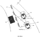
- FIG. 8 shows an exemplary navigation of an autonomous vehicle along the track upon detecting the one or more obstacles using an Inertial Measurement Unit (IMU) sensor, in accordance with some embodiments of the present disclosure
- FIG. 9 shows an exemplary safely parking of an autonomous vehicle using impulsive velocity, in accordance with some embodiments of the present disclosure.
- FIG. 10 shows an exemplary determination of new tentative position of an autonomous vehicle, in accordance with some embodiments of the present disclosure
- FIG. 11 shows an exemplary detection of reaching of safe parking space by an autonomous vehicle, in accordance with some embodiments of the present disclosure
- FIG. 12 shows an exemplary trajectory performance profile, in accordance with some embodiments of the present disclosure.
- FIG. 13 shows an exemplary velocity-distance profile data, in accordance with some embodiments of the present disclosure.
- any block diagrams herein represent conceptual views of illustrative systems embodying the principles of the present subject matter.
- any flow charts, flow diagrams, state transition diagrams, pseudo code, and the like represent various processes which may be substantially represented in computer readable medium and executed by a computer or processor, whether or not such computer or processor is explicitly shown.
- exemplary is used herein to mean “serving as an example, instance, or illustration.” Any embodiment or implementation of the present subject matter described herein as “exemplary” is not necessarily to be construed as preferred or advantageous over other embodiments.
- the present disclosure describes a method for safely parking an autonomous vehicle (AV). Based on the current position of the AV in a global path, an angular velocity and curvature required for the AV to reach a safe parking space towards an edge of a road may be determined, upon detecting non-working of at least one primary sensor among a plurality of primary sensors associated with the AV. Further, one or more obstacles proximal to the AV may be detected using one or more secondary sensors attached to the AV while navigating the AV along determined curvature.
- AV autonomous vehicle
- the AV may be navigated in a track by maintaining a safe distance from the one or more obstacles using remaining primary sensors among the plurality of primary sensors upon detecting presence of the one or more obstacles proximal to the AV in the determined curvature.
- the AV may be navigated along the determined curvature at determined angular velocity using the remaining primary sensors among the plurality of primary sensors and the one or more secondary sensors upon detecting absence of the one or more obstacles proximal to the AV in the determined curvature to reach the safe parking space towards the edge of the road.
- FIG. 1 shows an exemplary environment for safely parking an Autonomous Vehicle (AV) ( 102 ), in accordance with some embodiments of the present disclosure.
- the AV ( 102 ) may be associated with a plurality of primary sensors ( 104 ) and one or more secondary sensors ( 105 ).
- the plurality of primary sensors ( 104 ) may include an imaging sensor, a RADAR, a Light Imaging, Detection and Ranging (LiDAR), an Inertial Measurement Units (IMUs), a wheel encoder and the like.
- the one or more secondary sensors ( 105 ) may include an ultrasonic sensor, proximity sensor and the like.
- the AV ( 102 ) may use the plurality of primary sensors ( 104 ) for navigating along a road ( 101 ) or track from a source location to a destination location.
- the navigation unit ( 200 ) associated with the AV may be used to navigate the AV along the road ( 101 ) by generating and applying a determined combination of linear and angular velocities selected from a trajectory performance profile ( 205 ) based on the inputs from the one or more primary sensors ( 104 ).
- the generation of combination of the linear and the angular velocities may repeat after a predefined time period for example 100 ms and may be applied to the wheelbase of the AV ( 102 ) for navigating the AV ( 102 ) along the road ( 101 ).
- the one or more primary sensors ( 104 ) may be continuously monitored by the navigation unit ( 200 ) of the AV ( 102 ), to detect a failure or non-working or an anomaly of the at least one primary sensor among the plurality of primary sensors ( 104 ).
- the failure or non-working of the at least one primary sensor may be detected based on at least one of a presence or absence of a signal from the plurality of primary sensors ( 104 ), the range of values obtained from the signal of the plurality of primary sensors ( 104 ) and the like.
- the navigation unit ( 200 ) upon detecting the non-working of the at least one primary sensor among the plurality of primary sensors ( 104 ) associated with the AV ( 102 ), may determine, based on current position of the AV ( 102 ) in a global path, an angular velocity and a curvature ( 107 ) required for the AV ( 102 ) to reach a safe parking space towards the edge of the road ( 101 ) as shown in FIG. 1 .
- the navigation unit ( 200 ) may activate the one or more secondary sensors ( 105 ), to detect the one or more obstacles ( 103 ) proximal to the AV ( 102 ) during the navigation of the AV ( 102 ) along the determined curvature ( 107 ).
- the one or more secondary sensors ( 105 ) may transmit signals ( 106 ) and based on the received reflected signals ( 106 ) detect the one or more obstacles ( 103 ) proximal to the AV ( 102 ).
- the detection of the one or more obstacles proximal to the AV ( 102 ) includes detecting at least one of the one or more obstacles in front of the AV ( 102 ) and the one or more obstacles behind the AV ( 102 ) in the direction of the determined curvature ( 107 ), and determining distance of the one or more obstacles detected by the AV ( 102 ).
- the one or more obstacles ( 103 ) may include at least one of a vehicle navigating in front of the AV ( 102 ) along the direction of the determined curvature ( 107 ), a vehicle approaching the AV ( 102 ) from behind the AV ( 102 ) along the direction of the determined curvature ( 107 ), a vehicle statically parked along the direction of the determined curvature ( 107 ), a barrier of the road ( 101 ), and the like.
- the navigation unit ( 200 ) based on the one or more obstacles ( 103 ) navigates the AV ( 102 ) in a track along the road ( 101 ) by maintaining a safe distance from the one or more obstacles ( 103 ) using remaining primary sensors among the plurality of primary sensors ( 104 ).
- the remaining primary sensors may be indicative of the one or more primary sensors among the plurality of primary sensors ( 104 ) in a working condition.
- the navigation unit ( 200 ) may navigate the AV ( 102 ) in a track along the road ( 101 ) by maintaining a safe distance from the one or more obstacles ( 103 ) using the remaining primary sensors including at least one of the camera sensor, LiDAR sensor and IMU sensor in the working condition.
- the navigation unit ( 200 ) upon detecting absence of the one or more obstacles ( 103 ) navigates the AV ( 102 ) along the determined curvature ( 107 ) at determined angular velocity using the remaining primary sensors among the plurality of primary sensors ( 104 ) and the one or more secondary sensors ( 105 ) to reach the safe parking space towards the edge of the road ( 101 ) as shown in FIG. 1 .
- the navigation unit ( 200 ) detects the reaching of the safe parking space by the AV ( 102 ) using the one or more secondary sensors ( 105 ) by identifying at least one of a pedestrian area within a predefined distance from the AV ( 102 ) and a low lying area with respect to the edge of the road ( 101 ) within the predefined distance from the AV ( 102 ).
- the predefined distance may be set to, for example, 1 meter from the current position of the AV ( 102 ).
- the safe parking space of the AV ( 102 ) may be towards the left side edge of the road ( 101 ).
- the safe parking space of the AV ( 102 ) may be towards the right-side edge of the road ( 101 ).
- the one or more secondary sensors ( 105 ) may be housed at the four corners of the AV ( 102 ).
- the one or more secondary sensors ( 105 ) housed in front of the AV ( 102 ) may be used to detect the one or more obstacles ( 103 ) ahead of the AV ( 102 ) along the left and right directions of the AV ( 102 ).
- the one or more secondary sensors ( 105 ) housed at back of the AV ( 102 ) may be used to detect the one or more obstacles ( 103 ) behind the AV ( 102 ) along the left and right directions of the AV ( 102 ).
- the navigation unit ( 200 ) may reduce the speed of the AV ( 102 ) upon detecting the non-working of the at least one primary sensor among the plurality of primary sensors ( 104 ).
- FIG. 2 shows a detailed block diagram of a navigation unit ( 200 ), in accordance with some embodiments of the present disclosure.
- the navigation unit ( 200 ) may be communicatively coupled to the plurality of primary sensors ( 104 ) and the one or more secondary sensors ( 105 ).
- the navigation unit ( 200 ) may include a Central Processing Unit (“CPU” or “processor”) ( 203 ) and a memory ( 202 ) storing instructions executable by the processor ( 203 ).
- the processor ( 203 ) may include at least one data processor for executing user or system-generated requests.
- the memory ( 202 ) may be communicatively coupled to the processor ( 203 ).
- the navigation unit ( 200 ) further includes an Input/Output (I/O) interface ( 201 ).
- I/O Input/Output
- the I/O interface ( 201 ) may be coupled with the processor ( 203 ) through which an input signal or/and an output signal may be communicated.
- the navigation unit ( 200 ) may receive the signals from the plurality of primary sensors ( 104 ) and the one or more secondary sensors ( 105 ) through the I/O interface ( 201 ).
- the navigation unit ( 200 ) may include data ( 204 ) and modules ( 211 ).
- the data ( 204 ) and modules ( 211 ) may be stored in the memory ( 202 ) configured in the navigation unit ( 200 ) as shown in the FIG. 2 .
- the data ( 204 ) may include, for example, a trajectory performance profile ( 205 ), curvature data ( 206 ), sensor data ( 207 ), obstacle data ( 208 ), velocity-distance profile data ( 209 ) and other data ( 210 ).
- data ( 204 ) are described herein in detail.
- the trajectory performance profile ( 205 ) may include a distance covered by the AV ( 102 ) corresponding to an applied linear velocity for a duration of “t” seconds at a certain weight condition of the AV ( 102 ). Further, the trajectory performance profile ( 205 ) may include the distance covered by the AV ( 102 ) at a certain linear velocity of the AV ( 102 ) as shown in TABLE-1 of FIG. 12 and a lateral shift covered by the AV ( 102 ) corresponding to the angular velocity applied to the AV ( 102 ), where the AV ( 102 ) may be travelling with a certain linear velocity as shown in TABLE-2A and TABLE-2B of the FIG. 12 .
- TABLE-2B of the FIG. 12 indicates the distance covered by the AV ( 102 ) travelling at a linear velocity of 50 km/sec and the lateral shift covered by the AV ( 102 ) for the applied angular velocity.
- the curvature data ( 206 ) may include a measured curvature ( 401 ).
- the measured curvature ( 401 ) indicates a curve of a road segment ahead of the AV ( 102 ) which is determined to navigate the AV ( 102 ) along the global path when the plurality of primary sensors ( 104 ) is in working condition.
- the global path may be a path determined for navigating the AV ( 102 ) from the source location to the destination location based on a reference map.
- the sensor data ( 207 ) may include signals ( 106 ) received from the plurality of primary sensors ( 104 ) and one or more secondary sensors ( 105 ).
- an image captured by an imaging sensor for example, visible light camera, infrared camera and the like
- the sensor data may include one or more objects detected, distance of the objects detected from the signals ( 106 ) received from the plurality of primary sensors ( 104 ) and one or more secondary sensors ( 105 ).
- the one or more objects may include at least one of vehicles, road edge, one or more lane markers, road signs, pedestrian, pedestrian area, road bump, low lying area with respect to the road edge and the like.
- the obstacle data ( 208 ) may include position of the one or more obstacles ( 103 ) proximal to the AV ( 102 ) and the distance of the one or more obstacles from the AV ( 102 ).
- the one or more obstacles may be detected at a distance of 2 meters in front of the AV ( 102 ) along the left side of the AV ( 102 ).
- the velocity-distance profile data ( 209 ) may include an angular shift achieved per second by the AV ( 102 ) corresponding to the current linear velocity of the AV ( 102 ), and the distance covered by the AV ( 102 ) for a duration of “t” seconds as shown in TABLE-1 of the FIG. 13 .
- the velocity-distance profile data ( 209 ) may be used to navigate the AV ( 102 ) using the working primary sensor for example IMU.
- the other data ( 210 ) may include the global path from the source location to the destination location, the reference map for localization of the AV ( 102 ) and the like.
- the data ( 204 ) may be stored in the memory ( 202 ) in form of various data structures. Additionally, the data ( 204 ) may be organized using data models, such as relational or hierarchical data models.
- the other data ( 210 ) may store data, including temporary data and temporary files, generated by the modules ( 211 ) for performing the various functions of the navigation unit ( 200 ).
- the data ( 204 ) stored in the memory ( 202 ) may be processed by the modules ( 211 ) of the navigation unit ( 200 ).
- the modules ( 211 ) may be stored within the memory ( 202 ).
- the modules ( 211 ) communicatively coupled to the processor ( 203 ) configured in the navigation unit ( 200 ), may also be present outside the memory ( 202 ) as shown in FIG. 2 and implemented as hardware.
- modules ( 211 ) may refer to an Application Specific Integrated Circuit (ASIC), a FPGA (Field Programmable Gate Array), an electronic circuit, a processor (shared, dedicated, or group) and memory ( 202 ) that execute one or more software or firmware programs, a combinational logic circuit, and/or other suitable components that provide the described functionality.
- the modules ( 211 ) may be implemented using at least one of ASICs and FPGAs.
- the modules ( 211 ) may include, for example, sensor failure detection module ( 212 ), safe parking space detection module ( 213 ), curvature measuring module ( 214 ), obstacle detection module ( 215 ), image sensor module ( 216 ), LiDAR sensor module ( 217 ), IMU sensor module ( 218 ), and other module ( 219 ). It may be appreciated that such afore-mentioned modules ( 211 ) may be represented as a single module or a combination of different modules.
- the sensor failure detection module ( 212 ) may be used to detect the failure or non-working or anomaly of the at least one primary sensor among the plurality of sensors associated with the navigation unit ( 200 ) of the AV ( 102 ).
- the safe parking space detection module ( 213 ) may be used to detect the reaching of the safe parking space by the AV ( 102 ), using the one or more secondary sensors ( 105 ) by identifying at least one of a pedestrian area within a predefined distance from the AV ( 102 ) and a low lying area with respect to the edge of the road within the predefined distance from the AV ( 102 ).
- the predefined distance may be set to the distance of the road ( 101 ) from the AV ( 102 ).
- the safe parking space may be towards the road edge in the left direction of the AV ( 102 ).
- the safe parking space may be towards the road edge in the right direction of the AV ( 102 ).
- the curvature measuring module ( 214 ) may be used to determine a curvature required for the AV ( 102 ) to reach safe parking space towards an edge of a road ( 101 ).
- the navigation unit ( 200 ) may determine the curvature as linear path for guided shifting of the AV ( 102 ) to reach the safe parking space as shown in FIG. 9 .
- the navigation unit ( 200 ) may determine a curvature more than the measured curvature ( 401 ).
- the determined curvature ( 107 ) may be 2 times the measured curvature ( 401 ).
- the navigation unit ( 200 ) may determine a linear path for the AV ( 102 ) to reach safe parking space towards an edge of a road ( 101 ) in case of the road ( 101 ) being a straight path or having a curve to the direction opposite to the safe parking space.
- the navigation unit ( 200 ) may determine a curvature more than the measured curvature ( 401 ) for the AV ( 102 ) to reach safe parking space towards an edge of a road ( 101 ) in case of the road ( 101 ) having a curve in the direction of the safe parking space.
- the obstacle detection module ( 215 ) may be used to detect the one or more obstacles ( 103 ) proximal to the AV ( 102 ) along the determined curvature ( 107 ).
- the one or more secondary sensors ( 105 ) may be used to detect the one or more obstacles ( 103 ) proximal to the AV.
- the one or more secondary sensors ( 105 ) may transmit signals ( 106 ) and measure the time taken for the reflected signals ( 106 ) from the one or more obstacles to reach the one or more secondary sensors ( 105 ). Further, the distance from the one or more obstacles ( 103 ) may be determined using the relationship between distance, time and speed.
- the image sensor module ( 216 ) may be used to navigate the AV ( 102 ) along a track on the road ( 101 ) upon detecting the one or more obstacles ( 103 ) in the determined curvature ( 107 ).
- the image sensor module ( 216 ) may include a visible light camera, an infrared camera and the like.
- the image sensor module ( 216 ) may capture images and detect the one or more objects such as road signs in the captured image using the existing image processing techniques like edge detection, object recognition and the like.
- the LiDAR sensor module ( 217 ) may be used to navigate the AV ( 102 ) along a track on the road ( 101 ) upon detecting the one or more obstacles ( 103 ) in the determined curvature ( 107 ).
- LiDAR stands for light imaging, detection and ranging.
- the LiDAR sensor module ( 217 ) may comprise a LiDAR sensor and controller/processor.
- the LiDAR sensor may emit invisible laser rays.
- the controller/processor may scan and detect objects in near vicinity or far vicinity of the LiDAR sensor and create a 3D map of the objects and surroundings around the LiDAR sensor.
- the Field of View (FOV) of the LiDAR sensor may comprise a range of angle measured in degrees around the AV ( 102 ) for emitting the laser rays to scan and detect the objects.
- the laser rays emitted by the LiDAR sensor travel outward until the rays encounter an object.
- the laser LiDAR data may be used for measuring the orientation of the object so that navigation unit ( 200 ) may navigate the AV ( 102 ) by maintaining the measured orientation with respect to the object.
- the IMU sensor module ( 218 ) may be used to navigate the AV ( 102 ) along a track on the road ( 101 ) upon detecting the one or more obstacles ( 103 ) in the determined curvature ( 107 ).
- the inertial measurement unit (IMU) may be used to directly measure three linear acceleration components and three angular rate components of the AV ( 102 ).
- the IMU may be used to measure one or more characteristics pertaining to the dynamics of the AV ( 102 ) for example location of the AV ( 102 ), position of the AV ( 102 ) on the road ( 101 ), direction of the AV ( 102 ), orientation of the AV ( 102 ) and velocity of the AV ( 102 ).
- the other module ( 219 ) may be used to generate and apply the determined combination of the linear and the angular velocities to the wheelbase of the AV ( 102 ), for navigating the AV ( 102 ) along the determined curvature ( 107 ).
- FIG. 3 shows a flowchart illustrating method steps for safely parking an AV ( 102 ) on sensor anomaly, in accordance with some embodiment of the present disclosure.
- the order in which the method 300 may be described is not intended to be construed as a limitation, and any number of the described method blocks may be combined in any order to implement the method. Additionally, individual blocks may be deleted from the methods without departing from the scope of the subject matter described herein. Furthermore, the method may be implemented in any suitable hardware, software, firmware, or combination thereof.
- the navigation unit ( 200 ) upon detecting the non-working of at least one primary sensor among the plurality of primary sensors ( 104 ) associated with the AV ( 102 ), may determine an angular velocity and curvature ( 107 ) required for the AV ( 102 ) to reach a safe parking space towards an edge of a road, based on a current position of the AV ( 102 ) in a global path.
- the global path may include a planned trajectory from a source location to the destination location.
- the non-working of the at least one primary sensor among the plurality of primary sensors ( 104 ) associated with the AV ( 102 ) may be detected by the navigation unit ( 200 ) based on inputs received from the plurality of primary sensors ( 104 ).
- the navigation unit ( 200 ) may determine the angular velocity and the curvature ( 107 ) by identifying a portion of the global path subsequent to the current position of the AV ( 102 ) to be at least one of a straight path or a path having a curve to a direction opposite to the safe parking space for selecting a predefined angular velocity and a predefined curvature from a trajectory performance profile ( 205 ).
- the safe parking space may be towards the left end of the road ( 101 ), therefore the path having a curve towards the right of the AV ( 102 ) may be regarded as the path having curve to a direction opposite to the safe parking space.
- the safe parking space may be towards the right end of the road ( 101 ), therefore the path having a curve towards the left of the AV ( 102 ) may be regarded as the path having curve to a direction opposite to the safe parking space.
- the navigation unit ( 200 ) may select the predefined angular velocity and a predefined curvature from a trajectory performance profile ( 205 ) based on a current speed of the AV ( 102 ), a current load of the AV ( 102 ) and the like.
- the navigation unit ( 200 ) may identify the portion of the global path subsequent to the current position of the AV ( 102 ), the path having the curve on a direction similar to the safe parking space for selecting the angular velocity from the trajectory performance profile ( 205 ) to follow the curve more than a measured curvature ( 401 ).
- the measured curvature ( 401 ) may be computed by determining at least one of a road width, a lane information, a current velocity of the AV ( 102 ) and a distance to reach the safe parking space using the remaining primary sensors from the plurality of primary sensors ( 104 ) that are in working condition and the one or more secondary sensors ( 105 ).
- the path having a curve towards the left of the AV ( 102 ) may be regarded as the path having a curve on the direction similar to the safe parking space.
- the path having a curve towards the right of the AV ( 102 ) may be regarded as the path having a curve on the direction similar to the safe parking space.
- the AV ( 102 ) present at a “POSITION-A” detects the non-working of at least one primary sensor among the plurality of primary sensors ( 104 ) associated with the AV ( 102 ).
- the AV ( 102 ) using the global path from the current position denoted as “POSITION-A” may identify the portion of the global path subsequent to the current position (“POSITION-A”) of the AV ( 102 ).
- the portion of the global path may be at least one of a straight path as shown in FIG. 4B , a curve towards the right side of the AV ( 102 ) from the current position (“POSITION-A”) of the AV ( 102 ) FIG. 4A and a curve towards the left side of the AV ( 102 ) from the current position (“POSITION-A”) of the AV ( 102 ) as shown in FIG. 4C .
- the portion of the global path having a curve to the right may be regarded as the path having a curve opposite to the safe parking space (“POSITION-B”) as shown in FIG. 4A .
- the portion of the global path having a curve towards the left direction of the AV ( 102 ) may be regarded as the path having a curve on the same direction of the safe parking space (“POSMON-B”) as shown in FIG. 4C . Therefore, for the portion of the global path having the straight path as shown in FIG. 4B or the path having the curve towards the right as shown in FIG.
- the AV ( 102 ) may select a predefined angular velocity and a predefined curvature from the trajectory performance profile ( 205 ) for navigating to the safe parking space (“POSITION-B”) as shown in FIG. 4A and FIG. 4B .
- the navigation unit ( 200 ) may navigate the AV ( 102 ) using a guided shifting of the AV ( 102 ) to reach the safe parking space as shown in FIG. 9 . Furthermore, for the portion of the global path having the curve towards the left side of the AV ( 102 ) as shown in FIG.
- the measured curvature ( 401 ) may be computed by determining at least one of a road width, a lane information, a current velocity of the AV and a distance to reach the safe parking space (“POSITION-B”) using the remaining primary sensors from the plurality of primary sensors ( 104 ) that are in working condition and the one or more secondary sensors ( 105 ). Thereafter, the AV ( 102 ) may select the angular velocity from the trajectory performance profile ( 205 ) to follow the curve denoted as determined curvature ( 107 ) more than a measured curvature ( 401 ) for navigating to the safe parking space (“POSITION-B”) as shown in FIG. 4C .
- the determined curvature ( 107 ) may be set to twice the measured curvature ( 401 ).
- the curvature may be determined as a ratio of variation in the combination of the linear and angular velocities consecutively applied to the AV ( 102 ) and a distance covered by the AV ( 102 ) within the time duration of application of the combination of the linear and angular velocities.
- the curvature denoted as “K” may be determined using the consecutively applied combination of the linear and angular velocities denoted by “T1” and “T2” and the instantaneous distance covered by the AV ( 102 ) denoted by “D”.
- the curvature “K” may be determined using the equation given below:
- the navigation unit ( 200 ) may detect the one or more obstacles ( 103 ) proximal to the AV ( 102 ) using the one or more secondary sensors ( 105 ) attached to the AV ( 102 ), while navigating the AV ( 102 ) along determined curvature ( 107 ).
- the navigation unit ( 200 ) may detect the presence of one or more obstacles ( 103 ) proximal to the AV ( 102 ) by detecting at least one of the one or more obstacles ( 103 ) in front of the AV ( 102 ) and the one or more obstacles behind the AV ( 102 ) while navigating the AV ( 102 ) along the determined curvature. Further, the navigation unit ( 200 ) may determine the distance of the one or more obstacles ( 103 ) detected to the AV ( 102 ).
- the navigation unit ( 200 ) may detect the presence of the one or more obstacles ( 103 ) proximal to the AV ( 102 ) using the one or more secondary sensors ( 105 ).
- the ultrasonic sensors may be used as one or more secondary sensors ( 105 ).
- the ultrasonic sensors may emit sound signals ( 106 ) at a frequency greater than the frequency of audio range required for humans to hear.
- the ultrasonic sensors may wait for the sound signals ( 106 ) to be reflected back from the one or more obstacles ( 103 ).
- the navigation unit ( 200 ) may calculate the distance to the one or more obstacles ( 103 ) from the AV ( 102 ) based on the time required for the reflected sound signals to reach the ultrasonic sensors and the speed of the emitted sound signals using the equation (1).
- the navigation unit ( 200 ) may detect one or more obstacles ( 103 ) adjacent to the AV ( 102 ) as shown in FIG. 5 . Further, the navigation unit ( 200 ) may detect the one or more obstacles ( 103 ) in front of the AV ( 102 ) along the determined curvature ( 107 ) as shown in FIG. 5 . Furthermore, the navigation unit ( 200 ) may detect the one or more obstacles ( 103 ) behind the AV ( 102 ) and approaching the AV ( 102 ), along the determined curvature ( 107 ) as shown in FIG. 5 .
- the navigation unit ( 200 ) may navigate the AV ( 102 ) in a track along the road ( 101 ), by maintaining a safe distance from the one or more obstacles ( 103 ) using remaining primary sensors among the plurality of primary sensors ( 104 ) upon detecting presence of the one or more obstacles ( 103 ) proximal to the AV ( 102 ), in the determined curvature ( 107 ).
- the navigation unit ( 200 ) may decide to navigate the AV ( 102 ) in the track distinct from the determined curvature ( 107 ) to avoid collision with the one or more obstacles ( 103 ).
- the navigation unit ( 200 ) may continue to navigate the AV ( 102 ) in a track distinct from the determined curvature ( 107 ) until the one or more obstacles ( 103 ) are far away from the AV ( 102 ) and not proximal to the AV ( 102 ).
- the navigation unit ( 200 ) may navigate the AV ( 102 ) along the track upon detecting the one or more obstacles ( 103 ) using the remaining primary sensors including an image sensor by identifying one or more lane markers ( 601 ) present on the track in the road ( 101 ). Further, the navigation unit ( 200 ) may measure a horizontal distance between the AV ( 102 ) and a lane marker among the one or more lane markers ( 601 ) adjacent to the AV ( 102 ). Furthermore, the navigation unit ( 200 ) may navigate the AV ( 102 ) by maintaining the horizontal distance between the AV ( 102 ) and the one or more lane markers ( 601 ) by applying a combination of linear and angular velocities for navigating the AV ( 102 ). The navigation unit ( 200 ) may validate the track following of the AV ( 102 ) with a working IMU primary sensor.
- the navigation unit ( 200 ) may use an imaging sensor for example an visible light camera, infrared camera and the like, to identify the one or more lane markers ( 601 ) and an orientation of the one or more lane markers ( 601 ) from the AV ( 102 ) for navigating the AV ( 102 ) by maintaining a safe distance from the one or more obstacles ( 103 ).
- the distance and orientation of the one or more lane markers ( 601 ) from the AV ( 102 ) may be computed using the existing image processing techniques.
- the AV ( 102 ) at “POSITION-A” on the road ( 101 ) may identify at least one lane marker among the one or more lane markers ( 601 ) at distance denoted as “L” from the AV ( 102 ). Based on the distance “L” an angle of visibility denoted as ‘p’ may be measured using the existing image processing techniques.
- the navigation unit ( 200 ) may navigate the AV ( 102 ) (for example from “POSITION-A” to “POSITION-B”) by applying the combination of linear and angular velocities, along the track on the road ( 101 ) by maintaining the horizontal distance “D” between the AV ( 102 ) and the one or more lane markers ( 601 ) as shown in FIG. 6 .
- the one or more lane markers ( 601 ) beyond a threshold distance “Lg.” may not be identified for computing the horizontal distance “D”.
- the navigation unit ( 200 ) may generate and apply the combination of linear and angular velocities to navigate the AV ( 102 ) towards leftward direction of the road ( 101 ) until the horizontal distance of ‘D’ is maintained.
- the navigation unit ( 200 ) may generate and apply the combination of linear and angular velocities to navigate the AV ( 102 ) towards rightward direction of the road ( 101 ) until the horizontal distance of ‘D’ is maintained.
- the navigation unit ( 200 ) may navigate the AV ( 102 ) along the track upon detecting the one or more obstacles ( 103 ) using the remaining primary sensors including a LiDAR sensor, by identifying a closest straight line ( 701 ) from a plurality of straight line clusters in parallel to vehicle orientation within a Field of View (FOV) of the AV ( 102 ), wherein the plurality of straight line clusters are a reflection of LiDAR sensor rays projected on the one or more obstacles ( 103 ) proximal to the AV ( 102 ). Further, determining orientation of the closest straight line ( 701 ) and maintaining the orientation of the closest straight line ( 701 ) by applying the combination of linear and angular velocities to the AV ( 102 ) for navigating the AV ( 102 ).
- FOV Field of View
- the navigation unit ( 200 ) navigates the AV ( 102 ) along the track in the road ( 101 ) by maintaining the same orientation with at least one obstacle among the one or more obstacles ( 103 ) using a LiDAR sensor.
- the at least one obstacle may include at least one vehicle proximal to the AV ( 102 ) moving on the road ( 101 ) in the direction of the determined curvature ( 107 ).
- the LiDAR sensor of the AV ( 102 ) may receive reflection of the emitted LiDAR sensor rays from the at least one vehicle proximal to the AV ( 102 ).
- the reflection of the emitted LiDAR sensor rays may include a cluster of straight lines within the Field of View (FOV).
- the navigation unit ( 200 ) may identify one of the closest straight line ( 701 ) parallel to the AV ( 102 ) in the direction of the determined curvature ( 107 ) from the cluster of straight lines within FOV obtained from reflection of the emitted LiDAR sensor rays. Further, the navigation unit ( 200 ) may determine the orientation of the closest straight line ( 701 ) parallel to the AV ( 102 ) by computing a slope denoted as “m” and an intercept denoted as “c”. The slope “m” may be computed using the equation given below:
- m ( y ⁇ ⁇ 1 - y ⁇ ⁇ 2 ) ( x ⁇ ⁇ 1 - x ⁇ ⁇ 2 ) ( 3 )
- (x1, y1) and (x2, y2) denote two LiDAR points (with respect to a LiDAR frame) of closest straight line ( 701 ) identified from the cluster of straight lines.
- the navigation unit ( 200 ) may navigate the AV ( 102 ) by maintaining the orientation of the closest straight line ( 701 ). For navigating the AV ( 102 ) in the determined orientation, the navigation unit ( 200 ) may modify the generated and applied combination of linear and angular velocities by adding or subtracting at least one of a positive or a negative angular velocity to the generated combination of linear and angular velocities.
- the navigation unit ( 200 ) may apply the combination of linear and angular velocities to the AV ( 102 ) in a suitable direction until the orientation of the AV ( 102 ) with the closest straight line ( 701 ) reaches “m”.
- the value of the slope “m” may be equal to a value 1 when the forward axis of the LiDAR sensor is in parallel to the one or more obstacles ( 103 ).
- the navigation unit ( 200 ) may navigate the AV ( 102 ) along the track upon detecting the one or more obstacles ( 103 ) using the remaining primary sensors including an Inertial Measurement Unit (IMU) sensor by computing the current position of the AV ( 102 ), after applying the combination of linear and angular velocities from the velocity-distance profile data ( 209 ) over a predefined time interval and a distance covered by the AV ( 102 ). Further, the navigation unit ( 200 ) may compare the current position of the AV ( 102 ) with a reference map to identify next portion of road segment to be followed along the track.
- IMU Inertial Measurement Unit
- the navigation unit ( 200 ) may determine the combination of linear and angular velocities from the velocity-distance profile data ( 209 ) as shown in TABLE-1 of FIG. 13 based on the next portion of the road segment from the current position of the AV ( 102 ) and apply the combination of linear and angular velocities determined for navigating the AV ( 102 ).
- the navigation unit ( 200 ) may use an IMU and wheel encoder for navigating the AV ( 102 ) along the track in the road ( 101 ) upon detecting the one or more obstacles ( 103 ).
- the navigation unit ( 200 ) may compute the current position (“POSITION-A”) of the AV ( 102 ) based on the velocity-distance profile data ( 209 ) and the reference map.
- the navigation unit ( 200 ) based a current position (“POSITION-A”) of the AV ( 102 ) in the reference map and a road ( 101 ) curvature ahead of the AV ( 102 ) may be obtained from the IMU sensor based on the previously applied combination of the linear and angular velocities and the velocity-distance profile data ( 209 ).
- the navigation unit ( 200 ) may determine the next portion of the road segment ahead of the AV ( 102 ) to be straight or having a “P” degree turn based on the IMU orientation change and velocity-distance profile data ( 209 ).
- the navigation unit ( 200 ) may determine the distance of the next portion of the road segment ahead of the AV ( 102 ) denoted as “L” meter based on the wheel encoder.
- the navigation unit ( 200 ) may determine the combination of linear and angular velocities from the velocity-distance profile data ( 209 ) for navigating the AV ( 102 ) along the determined next portion of the road segment ( 801 ) ahead of the AV ( 102 ) from “POSITION-A” to “POSITION-B” as shown in FIG. 8 .
- the navigation unit ( 200 ) may determine to achieve a 20° turn within a distance of 5 meters.
- the maximum angle shift achievable by the AV ( 102 ) per second may be 3.5° and the distance covered in 5 seconds may be 10 meters. Therefore, the maximum turn navigable by the AV ( 102 ) may be t*3.5°, where “t” may be the time duration of the application of the angular velocity to the AV ( 102 ).
- the navigation unit ( 200 ) may reduce the linear velocity of the AV ( 102 ) to achieve a higher angular orientation within the distance of 10 meters to navigate the AV ( 102 ) in the determined next portion of the road segment ( 801 ) from the current position of the AV ( 102 ). If t*3.5° is greater than 20°, the navigation unit ( 200 ) may apply less torque corresponding to the angular velocity to reduce the per second angular orientation of the AV ( 102 ) less than a maximum value of t*3.5°.
- the new position of the AV ( 102 ) may be determined by adding the distance denoted as “D” travelled by the AV ( 102 ) upon the application of the combination of linear and angular velocities.
- the distance “D” may be determined using the applied combination of linear and angular velocities denoted as “S” for time duration of “t” seconds using the velocity-distance profile.
- the navigation unit ( 200 ) may refer to the reference map and determine the next portion of the road segment from the current position of the AV ( 102 ). Thus, the navigation unit ( 200 ) may navigate the AV ( 102 ) based on a tentative calculation of a shifted position of the AV ( 102 ) with respect to the reference map.
- the navigation unit ( 200 ) may navigate the AV ( 102 ) along the determined curvature ( 107 ) at determined angular velocity using the remaining primary sensors among the plurality of primary sensors ( 104 ) and the one or more secondary sensors ( 105 ) upon detecting absence of the one or more obstacles ( 103 ) proximal to the AV ( 102 ) in the determined curvature ( 107 ) to reach safe parking space towards an edge of a road ( 101 ).
- the navigation unit ( 200 ) may navigate the AV ( 102 ) along the determined curvature ( 107 ) at the determined angular velocity by applying the determined angular velocity to the AV ( 102 ) for traversing in the determined curvature ( 107 ).
- the navigation unit ( 200 ) of the AV ( 102 ) at the “POSITION-A” on the road ( 101 ) detects the non-working of the at least one primary sensor among the plurality of sensors ( 104 ).
- the navigation unit ( 200 ) determines an angular velocity and a curvature required to safely park the AV ( 102 ) based on the current position of the AV ( 102 ). Further, the navigation unit ( 200 ) detects the absence of the one or more obstacles ( 103 ) proximal to the AV ( 102 ) and navigates the AV ( 102 ) along the determined curvature ( 107 ) to reach “POSITION-B” and thereafter to “POSITION-C”.
- the navigation unit ( 200 ) may apply the determined angular velocity to the AV ( 102 ) as an impulsive velocity for traversing in the determined curvature ( 107 ) from “POSITION-A” on the road ( 101 ) to “POSITION-B” and thereafter to “POSITION-C”.
- the impulsive velocity refers to gradually increasing the angular velocity from zero to a peak value and gradually decreasing it down to zero from the peak value.
- One such gradual increase of the angular velocity from zero to the peak value and gradual decrease from the peak value to zero may be denoted as a slot.
- the navigation unit ( 200 ) after applying one slot of angular velocity to the AV ( 102 ), determines a new tentative position of the AV ( 102 ) based on profile data.
- the new tentative position is determined as a combination of distance covered denoted as “D” by the AV ( 102 ) and the lateral shift denoted as “S” covered by the AV ( 102 ) as shown in FIG. 10 .
- D linear is a distance covered by AV ( 102 ) in “t” seconds at a linear velocity of “x” km/s corresponding to a weight condition of the AV ( 102 )
- K is an experimental constant having value between 0 to 1.
- the lateral shift “S” may be corresponding to the angular velocity applied may be determined form the profile data. The combination of the distance covered, and the lateral shift determines the new tentative position of the AV ( 102 ). As shown in FIG.
- the AV ( 102 ) in “POSITION-A” applies for example, the angular velocity of 0.8 rad at a linear velocity of 40 km/s for 5 s and let “K” be 1. Therefore, “D linear ” may be retrieved from the trajectory performance profile ( 205 ) corresponding to the linear velocity of 40 km/s and time of 5 s as 16 m. The distance covered “D” may be computed using the equation (5) as 12.8 m as shown in FIG. 10 . Further, the lateral shift “S” corresponding to the angular velocity of 0.8 rad applied to the AV ( 102 ) may be selected from the profile data as 0.35 m as shown in FIG. 12 . The new tentative position of the AV ( 102 ) is at “POSITION-B” as shown in FIG. 10 with the distance of 12.8 m and a lateral shift of 0.35 m covered by the AV ( 102 ).
- the navigation unit ( 200 ) detects the presence of the one or more obstacles ( 103 ) proximal to the AV ( 102 ) using the one or more secondary sensors ( 105 ).
- the navigation unit ( 200 ) navigates the AV ( 102 ) from “POSITION-C” to “POSITION-D” by maintaining a safe distance from the one or more obstacles ( 103 ) using the remaining primary sensor among the plurality of primary sensors ( 104 ).
- the navigation unit ( 200 ) detects the absence of the one or more obstacles ( 103 ) and navigates the AV ( 102 ) along the determined curvature ( 107 ) using the trajectory performance profile ( 205 ) as shown in FIG. 12 , from “POSITION-D” to “POSITION-H” via “POSITION-E”, “POSITION-F”, “POSITION-G” by applying the determined angular velocity as the impulsive velocity as shown in FIG. 9 . Finally, the navigation unit ( 200 ) safely parks the AV ( 102 ) at the “POSITION-H” upon detecting the reaching of the safe parking space by the AV ( 102 ), using the one or more secondary sensors ( 105 ).
- the navigation unit ( 200 ) may detect the reaching of the safe parking space by the AV ( 102 ), using the one or more secondary sensors ( 105 ) by identifying at least one of a pedestrian area within a predefined distance from the AV ( 102 ) and a low lying area with respect to the edge of the road ( 101 ) within the predefined distance from the AV ( 102 ).
- the navigation unit ( 200 ) may detect the reaching of the safe parking space by the AV ( 102 ), using the one or more secondary sensors ( 105 ). Based on the signals received due to reflection of the emitted signals from the one or more secondary sensors ( 105 ) the distance of the safe parking space may be computed using the equation (1). Further, if the computed distance of the safe parking space is lesser than the predefined distance from the AV ( 102 ) for example 2 meters, the navigation unit ( 200 ) may identify the safe parking of the AV ( 102 ).
- the distance of the pedestrian area from the AV may be lesser than the predefined distance from the road ( 101 ) to the AV ( 102 ), thus the navigation unit ( 200 ) detects the reaching of the safe parking space by the AV ( 102 ) as shown in FIG. 11 .
- the distance of the low lying area from the AV may be greater than the predefined distance from the road ( 101 ) to the AV ( 102 ), thus the navigation unit ( 200 ) detects the reaching of the safe parking space by the AV ( 102 ).
- the method for safely parking the AV ( 102 ) on sensor anomaly includes determining an angular velocity and curvatures required to safely park the AV ( 102 ) upon detecting the non-working of the at least one primary sensor.
- the one or more obstacles ( 103 ) in the determined curvature ( 107 ) and reaching of the safe parking space by the AV ( 102 ) may be determined using the one or more secondary sensors ( 105 ). Further, upon detecting one or more obstacles ( 103 ), the AV ( 102 ) may navigate along the track by maintaining a safe distance from the one or more obstacles using the remaining primary sensors among the plurality of primary sensors ( 104 ).
- the claimed steps as discussed above are not routine, conventional, or well understood in the art, as the claimed steps enable the following solutions to the existing problems in conventional technologies. Further, the claimed steps clearly bring an improvement in the functioning of the device itself as the claimed steps provide a technical solution to a technical problem.
- an embodiment means “one or more (but not all) embodiments of the invention(s)” unless expressly specified otherwise.
- FIG. 3 show certain events occurring in a certain order. In alternative embodiments, certain operations may be performed in a different order, modified or removed. Moreover, steps may be added to the above described logic and still conform to the described embodiments. Further, operations described herein may occur sequentially or certain operations may be processed in parallel. Yet further, operations may be performed by a single processing unit or by distributed processing units.
Abstract
Description
D=L*cos(Ø) (2)
where Ø=90−β, as shown in
where (x1, y1) and (x2, y2) denote two LiDAR points (with respect to a LiDAR frame) of closest straight line (701) identified from the cluster of straight lines. The intercept “c” may be computed using the one of the LiDAR point (x1, y1), the computed slope “m”, and an equation of a straight line given below:
y1=m*x1+c (4)
D=D linear *K*angular velocity applied (5)
Where Dlinear is a distance covered by AV (102) in “t” seconds at a linear velocity of “x” km/s corresponding to a weight condition of the AV (102), “K” is an experimental constant having value between 0 to 1. Further, the lateral shift “S” may be corresponding to the angular velocity applied may be determined form the profile data. The combination of the distance covered, and the lateral shift determines the new tentative position of the AV (102). As shown in
| | Description | ||
| 101 | |
||
| 102 | Autonomous Vehicle (AV) | ||
| 103 | One or |
||
| 104 | Plurality of |
||
| 105 | One or more |
||
| 106 | |
||
| 107 | |
||
| 200 | Navigation Unit | ||
| 201 | I/ |
||
| 202 | |
||
| 203 | |
||
| 204 | |
||
| 205 | |
||
| 206 | |
||
| 207 | |
||
| 208 | Obstacle Data | ||
| 209 | Velocity- |
||
| 210 | |
||
| 211 | |
||
| 212 | Sensor |
||
| 213 | Safe |
||
| 214 | |
||
| 215 | |
||
| 216 | |
||
| 217 | LiDAR sensor Module | ||
| 218 | Inertial Measurement |
||
| 219 | |
||
| 401 | Measured |
||
| 601 | One or |
||
| 701 | Closest |
||
| 801 | Determined next portion of the road segment | ||
Claims (18)
Applications Claiming Priority (2)
| Application Number | Priority Date | Filing Date | Title |
|---|---|---|---|
| IN201941033826 | 2019-08-22 | ||
| IN201941033826 | 2019-08-22 |
Publications (2)
| Publication Number | Publication Date |
|---|---|
| US20210056326A1 US20210056326A1 (en) | 2021-02-25 |
| US11301700B2 true US11301700B2 (en) | 2022-04-12 |
Family
ID=74645330
Family Applications (1)
| Application Number | Title | Priority Date | Filing Date |
|---|---|---|---|
| US16/595,518 Active 2040-06-19 US11301700B2 (en) | 2019-08-22 | 2019-10-08 | System and method for safely parking an autonomous vehicle on sensor anomaly |
Country Status (1)
| Country | Link |
|---|---|
| US (1) | US11301700B2 (en) |
Citations (10)
| Publication number | Priority date | Publication date | Assignee | Title |
|---|---|---|---|---|
| US6151539A (en) | 1997-11-03 | 2000-11-21 | Volkswagen Ag | Autonomous vehicle arrangement and method for controlling an autonomous vehicle |
| US9523984B1 (en) | 2013-07-12 | 2016-12-20 | Google Inc. | Methods and systems for determining instructions for pulling over an autonomous vehicle |
| US20170123428A1 (en) | 2015-11-04 | 2017-05-04 | Zoox, Inc. | Sensor-based object-detection optimization for autonomous vehicles |
| US20170297565A1 (en) * | 2016-04-14 | 2017-10-19 | Ford Global Technologies, Llc | Autonomous vehicle parking and transition to manual control |
| US10114374B2 (en) | 2016-11-16 | 2018-10-30 | Baidu Usa Llc | Emergency handling system for an autonomous driving vehicle (ADV) |
| US20190027042A1 (en) * | 2016-01-12 | 2019-01-24 | Mitsubishi Heavy Industries, Ltd. | Parking support system, parking support method and program |
| US20200094816A1 (en) * | 2018-09-24 | 2020-03-26 | Ford Global Technologies, Llc | Vehicle system and method for setting variable virtual boundary |
| US20200122775A1 (en) * | 2018-10-18 | 2020-04-23 | Clarion Co., Ltd. | Autonomous driving control device and autonomous driving path computation method |
| US20210163021A1 (en) * | 2018-10-30 | 2021-06-03 | Motional Ad Llc | Redundancy in autonomous vehicles |
| US20210171023A1 (en) * | 2018-03-20 | 2021-06-10 | Mobileye Vision Technologies Ltd. | Systems and methods for navigating a vehicle |
-
2019
- 2019-10-08 US US16/595,518 patent/US11301700B2/en active Active
Patent Citations (11)
| Publication number | Priority date | Publication date | Assignee | Title |
|---|---|---|---|---|
| US6151539A (en) | 1997-11-03 | 2000-11-21 | Volkswagen Ag | Autonomous vehicle arrangement and method for controlling an autonomous vehicle |
| US9523984B1 (en) | 2013-07-12 | 2016-12-20 | Google Inc. | Methods and systems for determining instructions for pulling over an autonomous vehicle |
| US20170057510A1 (en) * | 2013-07-12 | 2017-03-02 | Google Inc. | Methods And Systems For Determining Instructions For Pulling Over An Autonomous Vehicle |
| US20170123428A1 (en) | 2015-11-04 | 2017-05-04 | Zoox, Inc. | Sensor-based object-detection optimization for autonomous vehicles |
| US20190027042A1 (en) * | 2016-01-12 | 2019-01-24 | Mitsubishi Heavy Industries, Ltd. | Parking support system, parking support method and program |
| US20170297565A1 (en) * | 2016-04-14 | 2017-10-19 | Ford Global Technologies, Llc | Autonomous vehicle parking and transition to manual control |
| US10114374B2 (en) | 2016-11-16 | 2018-10-30 | Baidu Usa Llc | Emergency handling system for an autonomous driving vehicle (ADV) |
| US20210171023A1 (en) * | 2018-03-20 | 2021-06-10 | Mobileye Vision Technologies Ltd. | Systems and methods for navigating a vehicle |
| US20200094816A1 (en) * | 2018-09-24 | 2020-03-26 | Ford Global Technologies, Llc | Vehicle system and method for setting variable virtual boundary |
| US20200122775A1 (en) * | 2018-10-18 | 2020-04-23 | Clarion Co., Ltd. | Autonomous driving control device and autonomous driving path computation method |
| US20210163021A1 (en) * | 2018-10-30 | 2021-06-03 | Motional Ad Llc | Redundancy in autonomous vehicles |
Also Published As
| Publication number | Publication date |
|---|---|
| US20210056326A1 (en) | 2021-02-25 |
Similar Documents
| Publication | Publication Date | Title |
|---|---|---|
| CN109211249B (en) | Method and system for vehicle localization | |
| US10074281B2 (en) | Method and apparatus for determining lane identification in a roadway | |
| US9495602B2 (en) | Image and map-based detection of vehicles at intersections | |
| JP6401140B2 (en) | Joint probability modeling and estimation of the structure of intersections | |
| JP4343536B2 (en) | Car sensing device | |
| US8558679B2 (en) | Method of analyzing the surroundings of a vehicle | |
| US10621861B2 (en) | Method and system for creating a lane-accurate occupancy grid map for lanes | |
| EP3751459A1 (en) | Adjusting velocity of a vehicle for a curve | |
| KR20200042760A (en) | Vehicle localization method and vehicle localization apparatus | |
| WO2018061084A1 (en) | Self-position estimation method and self-position estimation device | |
| JP2005257314A (en) | Vehicle position detector | |
| JP7166325B2 (en) | Vehicle driving system, blind spot estimation method | |
| US20230384441A1 (en) | Estimating three-dimensional target heading using a single snapshot | |
| JP6781535B2 (en) | Obstacle determination device and obstacle determination method | |
| US11409302B2 (en) | Method for autonomous parking of a vehicle, and an autonomous vehicle thereof | |
| US10613540B2 (en) | Method and system for autonomously steering a vehicle in a reverse path in real-time | |
| JP4595773B2 (en) | Vehicle control device | |
| US10860021B2 (en) | Method and system for guiding an autonomous vehicle in a forward path in real-time | |
| JP5446559B2 (en) | Vehicle position calculation device and vehicle position calculation method | |
| US11301700B2 (en) | System and method for safely parking an autonomous vehicle on sensor anomaly | |
| US20180088587A1 (en) | Controlling Method and System for Autonomous Vehicle | |
| US11714186B2 (en) | Estimating target heading using a single snapshot | |
| JP6604052B2 (en) | Runway boundary estimation device and runway boundary estimation method | |
| US20240140438A1 (en) | Perception blockage prediction and supervision for performing information cloud localization | |
| US11747156B2 (en) | Method and system for generating maneuvering trajectories for a vehicle |
Legal Events
| Date | Code | Title | Description |
|---|---|---|---|
| AS | Assignment |
Owner name: WIPRO LIMITED, INDIA Free format text: ASSIGNMENT OF ASSIGNORS INTEREST;ASSIGNORS:KUMAR, BALAJI SUNIL;SARKAR, MANAS;SIGNING DATES FROM 20190628 TO 20190821;REEL/FRAME:050647/0347 |
|
| FEPP | Fee payment procedure |
Free format text: ENTITY STATUS SET TO UNDISCOUNTED (ORIGINAL EVENT CODE: BIG.); ENTITY STATUS OF PATENT OWNER: LARGE ENTITY |
|
| STPP | Information on status: patent application and granting procedure in general |
Free format text: DOCKETED NEW CASE - READY FOR EXAMINATION |
|
| STPP | Information on status: patent application and granting procedure in general |
Free format text: NON FINAL ACTION MAILED |
|
| STPP | Information on status: patent application and granting procedure in general |
Free format text: RESPONSE TO NON-FINAL OFFICE ACTION ENTERED AND FORWARDED TO EXAMINER |
|
| STPP | Information on status: patent application and granting procedure in general |
Free format text: NOTICE OF ALLOWANCE MAILED -- APPLICATION RECEIVED IN OFFICE OF PUBLICATIONS |
|
| STPP | Information on status: patent application and granting procedure in general |
Free format text: NOTICE OF ALLOWANCE MAILED -- APPLICATION RECEIVED IN OFFICE OF PUBLICATIONS |
|
| STPP | Information on status: patent application and granting procedure in general |
Free format text: NOTICE OF ALLOWANCE MAILED -- APPLICATION RECEIVED IN OFFICE OF PUBLICATIONS |
|
| STPP | Information on status: patent application and granting procedure in general |
Free format text: PUBLICATIONS -- ISSUE FEE PAYMENT VERIFIED |
|
| STCF | Information on status: patent grant |
Free format text: PATENTED CASE |