US11284385B2 - Device and method for handling a reception - Google Patents
Device and method for handling a reception Download PDFInfo
- Publication number
- US11284385B2 US11284385B2 US16/989,847 US202016989847A US11284385B2 US 11284385 B2 US11284385 B2 US 11284385B2 US 202016989847 A US202016989847 A US 202016989847A US 11284385 B2 US11284385 B2 US 11284385B2
- Authority
- US
- United States
- Prior art keywords
- communication device
- coreset
- tci
- pdsch
- dci
- Prior art date
- Legal status (The legal status is an assumption and is not a legal conclusion. Google has not performed a legal analysis and makes no representation as to the accuracy of the status listed.)
- Active, expires
Links
- 238000000034 method Methods 0.000 title description 33
- 238000004891 communication Methods 0.000 claims abstract description 190
- 238000012545 processing Methods 0.000 claims abstract description 14
- 230000011664 signaling Effects 0.000 claims description 40
- 230000005540 biological transmission Effects 0.000 claims description 7
- 238000010586 diagram Methods 0.000 description 30
- LKKMLIBUAXYLOY-UHFFFAOYSA-N 3-Amino-1-methyl-5H-pyrido[4,3-b]indole Chemical compound N1C2=CC=CC=C2C2=C1C=C(N)N=C2C LKKMLIBUAXYLOY-UHFFFAOYSA-N 0.000 description 29
- 102100031413 L-dopachrome tautomerase Human genes 0.000 description 29
- 101710093778 L-dopachrome tautomerase Proteins 0.000 description 29
- 230000008569 process Effects 0.000 description 26
- 101100465393 Homo sapiens PSMA1 gene Proteins 0.000 description 22
- 102100036042 Proteasome subunit alpha type-1 Human genes 0.000 description 22
- 101001076732 Homo sapiens RNA-binding protein 27 Proteins 0.000 description 7
- 102100025873 RNA-binding protein 27 Human genes 0.000 description 7
- 238000013507 mapping Methods 0.000 description 6
- 238000005259 measurement Methods 0.000 description 6
- 238000013500 data storage Methods 0.000 description 3
- 102100025248 C-X-C motif chemokine 10 Human genes 0.000 description 2
- 102100022840 DnaJ homolog subfamily C member 7 Human genes 0.000 description 2
- 101000903053 Homo sapiens DnaJ homolog subfamily C member 7 Proteins 0.000 description 2
- 101100222378 Mus musculus Cxcl10 gene Proteins 0.000 description 2
- 101100224522 Mus musculus Dppa3 gene Proteins 0.000 description 2
- 101100329418 Saccharomyces cerevisiae (strain ATCC 204508 / S288c) CRG1 gene Proteins 0.000 description 2
- 230000002776 aggregation Effects 0.000 description 2
- 238000004220 aggregation Methods 0.000 description 2
- 230000004075 alteration Effects 0.000 description 2
- 239000000969 carrier Substances 0.000 description 2
- 230000006870 function Effects 0.000 description 2
- 230000007774 longterm Effects 0.000 description 2
- 238000012986 modification Methods 0.000 description 2
- 230000004048 modification Effects 0.000 description 2
- 230000003287 optical effect Effects 0.000 description 2
- 230000008901 benefit Effects 0.000 description 1
- 238000004590 computer program Methods 0.000 description 1
- 230000002708 enhancing effect Effects 0.000 description 1
- 238000007726 management method Methods 0.000 description 1
- 238000005457 optimization Methods 0.000 description 1
- 230000000717 retained effect Effects 0.000 description 1
- 238000001356 surgical procedure Methods 0.000 description 1
Images


Classifications
-
- H—ELECTRICITY
- H04—ELECTRIC COMMUNICATION TECHNIQUE
- H04B—TRANSMISSION
- H04B7/00—Radio transmission systems, i.e. using radiation field
- H04B7/02—Diversity systems; Multi-antenna system, i.e. transmission or reception using multiple antennas
- H04B7/022—Site diversity; Macro-diversity
- H04B7/024—Co-operative use of antennas of several sites, e.g. in co-ordinated multipoint or co-operative multiple-input multiple-output [MIMO] systems
-
- H—ELECTRICITY
- H04—ELECTRIC COMMUNICATION TECHNIQUE
- H04W—WIRELESS COMMUNICATION NETWORKS
- H04W72/00—Local resource management
- H04W72/20—Control channels or signalling for resource management
- H04W72/23—Control channels or signalling for resource management in the downlink direction of a wireless link, i.e. towards a terminal
- H04W72/232—Control channels or signalling for resource management in the downlink direction of a wireless link, i.e. towards a terminal the control data signalling from the physical layer, e.g. DCI signalling
-
- H04W72/042—
-
- G—PHYSICS
- G08—SIGNALLING
- G08G—TRAFFIC CONTROL SYSTEMS
- G08G1/00—Traffic control systems for road vehicles
- G08G1/16—Anti-collision systems
-
- H—ELECTRICITY
- H04—ELECTRIC COMMUNICATION TECHNIQUE
- H04B—TRANSMISSION
- H04B7/00—Radio transmission systems, i.e. using radiation field
- H04B7/02—Diversity systems; Multi-antenna system, i.e. transmission or reception using multiple antennas
- H04B7/04—Diversity systems; Multi-antenna system, i.e. transmission or reception using multiple antennas using two or more spaced independent antennas
- H04B7/08—Diversity systems; Multi-antenna system, i.e. transmission or reception using multiple antennas using two or more spaced independent antennas at the receiving station
- H04B7/0868—Hybrid systems, i.e. switching and combining
- H04B7/088—Hybrid systems, i.e. switching and combining using beam selection
-
- H—ELECTRICITY
- H04—ELECTRIC COMMUNICATION TECHNIQUE
- H04J—MULTIPLEX COMMUNICATION
- H04J13/00—Code division multiplex systems
- H04J13/16—Code allocation
-
- H—ELECTRICITY
- H04—ELECTRIC COMMUNICATION TECHNIQUE
- H04L—TRANSMISSION OF DIGITAL INFORMATION, e.g. TELEGRAPHIC COMMUNICATION
- H04L5/00—Arrangements affording multiple use of the transmission path
- H04L5/0001—Arrangements for dividing the transmission path
- H04L5/0014—Three-dimensional division
- H04L5/0016—Time-frequency-code
-
- H—ELECTRICITY
- H04—ELECTRIC COMMUNICATION TECHNIQUE
- H04L—TRANSMISSION OF DIGITAL INFORMATION, e.g. TELEGRAPHIC COMMUNICATION
- H04L5/00—Arrangements affording multiple use of the transmission path
- H04L5/003—Arrangements for allocating sub-channels of the transmission path
- H04L5/0032—Distributed allocation, i.e. involving a plurality of allocating devices, each making partial allocation
-
- H—ELECTRICITY
- H04—ELECTRIC COMMUNICATION TECHNIQUE
- H04L—TRANSMISSION OF DIGITAL INFORMATION, e.g. TELEGRAPHIC COMMUNICATION
- H04L5/00—Arrangements affording multiple use of the transmission path
- H04L5/003—Arrangements for allocating sub-channels of the transmission path
- H04L5/0048—Allocation of pilot signals, i.e. of signals known to the receiver
- H04L5/0051—Allocation of pilot signals, i.e. of signals known to the receiver of dedicated pilots, i.e. pilots destined for a single user or terminal
-
- H—ELECTRICITY
- H04—ELECTRIC COMMUNICATION TECHNIQUE
- H04L—TRANSMISSION OF DIGITAL INFORMATION, e.g. TELEGRAPHIC COMMUNICATION
- H04L5/00—Arrangements affording multiple use of the transmission path
- H04L5/003—Arrangements for allocating sub-channels of the transmission path
- H04L5/0053—Allocation of signaling, i.e. of overhead other than pilot signals
-
- H—ELECTRICITY
- H04—ELECTRIC COMMUNICATION TECHNIQUE
- H04L—TRANSMISSION OF DIGITAL INFORMATION, e.g. TELEGRAPHIC COMMUNICATION
- H04L5/00—Arrangements affording multiple use of the transmission path
- H04L5/0091—Signaling for the administration of the divided path
- H04L5/0094—Indication of how sub-channels of the path are allocated
-
- H—ELECTRICITY
- H04—ELECTRIC COMMUNICATION TECHNIQUE
- H04W—WIRELESS COMMUNICATION NETWORKS
- H04W72/00—Local resource management
- H04W72/12—Wireless traffic scheduling
- H04W72/1263—Mapping of traffic onto schedule, e.g. scheduled allocation or multiplexing of flows
- H04W72/1273—Mapping of traffic onto schedule, e.g. scheduled allocation or multiplexing of flows of downlink data flows
-
- H—ELECTRICITY
- H04—ELECTRIC COMMUNICATION TECHNIQUE
- H04W—WIRELESS COMMUNICATION NETWORKS
- H04W72/00—Local resource management
- H04W72/20—Control channels or signalling for resource management
- H04W72/23—Control channels or signalling for resource management in the downlink direction of a wireless link, i.e. towards a terminal
- H04W72/231—Control channels or signalling for resource management in the downlink direction of a wireless link, i.e. towards a terminal the control data signalling from the layers above the physical layer, e.g. RRC or MAC-CE signalling
Definitions
- the present invention relates to a device and a method used in a wireless communication system, and more particularly, to a device and a method of handling a reception.
- LTE long-term evolution
- 3GPP 3rd Generation Partnership Project
- 3GPP Rel-8 3rd Generation Partnership Project
- 3GPP Rel-9 3rd Generation Partnership Project
- UMTS universal mobile telecommunication system
- the LTE system includes a new radio interface and a new radio network architecture that provides high data rate, low latency, packet optimization, and improved system capacity and coverage.
- a radio access network known as an evolved universal terrestrial radio access network (E-UTRAN) includes at least one evolved Node-B (eNB) for communicating with at least one user equipment (UE), and for communicating with a core network including a mobility management entity (MME), a serving gateway, etc., for Non-Access Stratum (NAS) control.
- E-UTRAN evolved universal terrestrial radio access network
- eNB evolved Node-B
- MME mobility management entity
- NAS Non-Access Stratum
- LTE-advanced (LTE-A) system is an evolution of the LTE system.
- the LTE-A system targets faster switching between power states, improves performance at the coverage edge of an eNB, increases peak data rate and throughput, and includes advanced techniques, such as carrier aggregation (CA), coordinated multipoint (CoMP) transmissions/reception, uplink (UL) multiple-input multiple-output (UL-MIMO), licensed-assisted access (LAA) (e.g., using LTE), etc.
- CA carrier aggregation
- CoMP coordinated multipoint
- UL-MIMO uplink
- LAA licensed-assisted access
- the UE and the eNB must support standards developed for the LTE-A system, such as the 3GPP Rel-1X standard or later versions.
- a fifth generation (5G) system (e.g., 5G new radio access network (5G-NR)) is an evolution of a continuous mobile broadband process to meet the requirements of 5G as introduced by International Mobile Telecommunications (IMT)-2020.
- the 5GS may include a radio access network (RAN) and a core network (CN).
- the RAN may include at least one base station (BS).
- the at least one BS may include an evolved Node-B (eNB) or a 5G Node-B (gNB).
- the eNB or the gNB may include at least one transmission point (TRP), for communicating with at least one UE and for communicating with the CN.
- the CN may include a MME, a SGW, an AMF, a UPF, etc., for a NAS control.
- Multiple TRPs may communicate with a UE via a beamforming.
- the UE may use multiple receive (Rx) filters to communicate with the TRPs.
- Rx receive
- the UE may use one of the Rx filters to receive signal from the TRPs, when the UE successfully decodes a downlink (DL) assignment. Accordingly, efficiency of resource utilization is degraded.
- the present invention therefore provides a device and a method for handling a reception to solve the abovementioned problem.
- a communication device for handling a reception comprises at least one storage device and at least one processing circuit, coupled to the at least one storage device.
- the at least one storage device stores instructions, and the at least one processing circuit is configured to execute the instructions of: receiving a DL control information (DCI) from a control resource set; and receiving a physical downlink (DL) shared channel (PDSCH) according to the DCI, wherein the DCI comprises a transmission configuration indicator (TCI) field, and the TCI field indicates a TCI codepoint corresponding to a first TCI state and a second TCI state.
- DCI DL control information
- PDSCH physical downlink shared channel
- a communication device for handling a reception comprises at least one storage device and at least one processing circuit, coupled to the at least one storage device.
- the at least one storage device stores instructions, and the at least one processing circuit is configured to execute the instructions of: receiving a DL control information (DCI) from a control resource set; and receiving a physical downlink (DL) shared channel (PDSCH) according to the DCI, wherein the control resource set (CORESET) is configured with a CORESET pool index.
- DCI DL control information
- PDSCH physical downlink shared channel
- FIG. 1 is a schematic diagram of a wireless communication system according to an example of the present invention.
- FIG. 2 is a schematic diagram of a communication device according to an example of the present invention.
- FIG. 3 is a flowchart of a process according to an example of the present invention.
- FIG. 4 is a schematic diagram of a communication device according to an example of the present invention.
- FIG. 5 is a flowchart of a process according to an example of the present invention.
- FIG. 6 is a schematic diagram of a TCI field-TCI state mapping table according to an example of the present invention.
- FIG. 7 is a schematic diagram of reception according to an example of the present invention.
- FIG. 8 is a schematic diagram of reception according to an example of the present invention.
- FIG. 9 is a schematic diagram of reception according to an example of the present invention.
- FIG. 10 is a schematic diagram of reception according to an example of the present invention.
- FIG. 11 is a schematic diagram of a schematic diagram of a CORESET-TCI state mapping table according to an example of the present invention.
- FIG. 12 is a flowchart of a process according to an example of the present invention.
- FIG. 13 is a schematic diagram of reception according to an example of the present invention.
- FIG. 14 is a schematic diagram of a reporting before a reception according to an example of the present invention.
- FIG. 15 is a schematic diagram of a reporting before a reception according to an example of the present invention.
- FIG. 16 is a schematic diagram of a reporting before a reception according to an example of the present invention.
- FIG. 17 is a schematic diagram of a reporting before a reception according to an example of the present invention.
- FIG. 1 is a schematic diagram of a wireless communication system 10 according to an example of the present invention.
- the wireless communication system 10 is briefly composed of transmission points (TRPs) TRP 1 and TRP 2 and a communication device CD.
- the wireless communication system 10 may support a time-division duplexing (TDD) mode, a frequency-division duplexing (FDD) mode, a TDD-FDD joint operation mode or a licensed-assisted access (LAA) mode. That is, the TRPs TRP 1 and TRP 2 and the communication device CD may communicate with each other via FDD carrier(s), TDD carrier(s), licensed carrier(s) (licensed serving cell (s)) and/or unlicensed carrier(s) (unlicensed serving cell(s)).
- TDD time-division duplexing
- FDD frequency-division duplexing
- LAA licensed-assisted access
- the wireless communication system 10 may support a carrier aggregation (CA). That is, the TRPs TRP 1 and TRP 2 and the communication device CD may communicate with each other via multiple serving cells (e.g., multiple serving carriers) including a primary cell (e.g., primary component carrier) and one or more secondary cells (e.g., secondary component carriers).
- multiple serving cells e.g., multiple serving carriers
- primary cell e.g., primary component carrier
- secondary cells e.g., secondary component carriers
- each of the TRPs TRP 1 and TRP 2 and the communication device CD are simply utilized for illustrating the structure of the wireless communication system 10 .
- each of the TRPs TRP 1 and TRP 2 may belong to a universal terrestrial radio access network (UTRAN) including at least one Node-B (NB) in a universal mobile telecommunications system (UMTS).
- UTRAN universal terrestrial radio access network
- NB Node-B
- UMTS universal mobile telecommunications system
- each of the TRPs TRP 1 and TRP 2 may belong to an evolved UTRAN (E-UTRAN) including at least one evolved NB (eNB) and/or at least one relay node in a long term evolution (LTE) system, a LTE-Advanced (LTE-A) system, an evolution of the LTE-A system, etc.
- LTE long term evolution
- LTE-A LTE-Advanced
- LTE-A evolution of the LTE-A system
- each of the TRPs TRP 1 and TRP 2 may belong to a next generation radio access network (NG-RAN) including at least one next generation Node-B (gNB) and/or at least one fifth generation (5G) base station (BS).
- NG-RAN next generation radio access network
- gNB next generation Node-B
- 5G fifth generation
- each of the TRPs TRP 1 and TRP 2 may belong to any BS conforming to a specific communication standard to communicate with the communication device CD.
- a NR is a standard defined for a 5G system (or 5G network) to provide a unified air interface with better performance.
- gNBs are deployed to realize the 5G system, which supports advanced features such as enhanced Mobile Broadband (eMBB), Ultra Reliable Low Latency Communications (URLLC), massive Machine Type Communications (mMTC), etc.
- eMBB provides broadband services with a greater bandwidth and a low/moderate latency.
- the URLLC provides applications (e.g., end-to-end communication) with properties of a higher security and a low latency.
- the examples of the applications include an industrial internet, smart grids, infrastructure protection, remote surgery and an intelligent transportation system (ITS).
- the mMTC is able to support internet-of-things (IoT) of the 5G system which include billions of connected devices and/or sensors.
- IoT internet-of-things
- the communication device CD may be a user equipment (UE), a low cost device (e.g., machine type communication (MTC) device), a device-to-device (D2D) communication device, a narrow-band internet of things (IoT) (NB-IoT), a mobile phone, a laptop, a tablet computer, an electronic book, a portable computer system, or combination thereof.
- UE user equipment
- MTC machine type communication
- D2D device-to-device
- NB-IoT narrow-band internet of things
- mobile phone a laptop, a tablet computer, an electronic book, a portable computer system, or combination thereof.
- each of the TRPs TRP 1 and TRP 2 and the communication device CD can be seen as a transmitter or a receiver according to direction (i.e., transmission direction), e.g., for an uplink (UL), the communication device CD is the transmitter and each of the TRPs TRP 1 and TRP 2 is the receiver, and for a downlink (DL), each of the TRPs TRP 1 and TRP 2 is the transmitter and the communication device CD is the receiver.
- direction i.e., transmission direction
- UL uplink
- the communication device CD is the transmitter and each of the TRPs TRP 1 and TRP 2 is the receiver
- DL downlink
- FIG. 2 is a schematic diagram of a communication device 20 according to an example of the present invention.
- the communication device 20 may be the communication device CD or any of the TRPs TRP 1 and TRP 2 shown in FIG. 1 , but is not limited herein.
- the communication device 20 may include at least one processing circuit 200 such as a microprocessor or Application Specific Integrated Circuit (ASIC), at least one storage device 210 and at least one communication interfacing device 220 .
- the at least one storage device 210 may be any data storage device that may store program codes 214 , accessed and executed by the at least one processing circuit 200 .
- ASIC Application Specific Integrated Circuit
- Examples of the at least one storage device 210 include but are not limited to a subscriber identity module (SIM), read-only memory (ROM), flash memory, random-access memory (RAM), Compact Disc Read-Only Memory (CD-ROM), digital versatile disc-ROM (DVD-ROM), Blu-ray Disc-ROM (BD-ROM), magnetic tape, hard disk, optical data storage device, non-volatile storage device, non-transitory computer-readable medium (e.g., tangible media), etc.
- SIM subscriber identity module
- ROM read-only memory
- flash memory random-access memory
- RAM Compact Disc Read-Only Memory
- DVD-ROM digital versatile disc-ROM
- BD-ROM Blu-ray Disc-ROM
- magnetic tape hard disk
- optical data storage device non-volatile storage device
- non-transitory computer-readable medium e.g., tangible media
- the at least one communication interfacing device 220 is preferably at least one transceiver and is used to transmit and receive signals (e.g., data, messages and/
- FIG. 3 is a flowchart of a process 30 according to an example of the present invention.
- the process 30 may be utilized in a communication device (e.g., the communication device shown in FIG. 1 ), to handle a reception.
- the process 30 may be compiled into the program codes 214 and includes the following steps:
- Step 300 Start.
- Step 302 Determine a first receive (Rx) filter according to a DL control information (DCI) for scheduling a physical DL shared channel (PDSCH).
- DCI DL control information
- Step 304 Receive the PDSCH according to the first Rx filter.
- Step 306 End.
- the communication device determines (e.g., calculates, obtains, selects and/or generates) a first Rx filter according to (e.g., by using) a DCI for scheduling a PDSCH. Then, the communication device receives the PDSCH according to (e.g., via) the first Rx filter. That is, the first Rx filter is determined according to the DCI for scheduling the PDSCH. Thus, the communication device knows how to receive the PDSCH.
- Realization of the process 30 is not limited to the above description. The following examples may be applied for realizing the process 30 .
- a offset (e.g., a time offset) between a first time instant for receiving the DCI and a second time instant for receiving the PDSCH is less than a threshold.
- the threshold is a time period for decoding the DCI, e.g., 7, 14, or 28 orthogonal frequency division multiplexing (OFDM) symbols. That is, the communication device does not (e.g., successfully) decodes the DCI yet, when the communication device receives the PDSCH.
- the DCI is included in a control resource set (CORESET) with the lowest CORESET identity (ID).
- the CORESET is in a slot where the communication device is scheduled to receive the PDSCH.
- the DCI includes a transmission configuration indicator (TCI) field.
- TCI transmission configuration indicator
- the TCI field indicates a TCI state.
- the TCI state indicates a reference signal (RS) corresponding to the Rx filter.
- the communication device receives the PDSCH according to (e.g., via) the first Rx filter while the communication device does not receive the PDSCH according to (e.g., via) a second Rx filter. That is, the communication device does not expect to receive the PDSCH according to another Rx filter which is not the first Rx filter.
- the first Rx filter belongs to a first panel of the communication device, wherein the first panel includes a first plurality of Rx filter which include the first Rx filter.
- the second Rx filter belongs to a second panel of the communication device, wherein the second panel includes a second plurality of Rx filter which include the second Rx filter.
- FIG. 4 is a schematic diagram of reception according to an example of the present invention.
- Two TRPs TRP 1 -TRP 2 communicate with each other according to (e.g., via) a backhaul BHL, and communicate with a communication device CD according to (e.g., via) a beamforming.
- the TRP TRP 1 transmits a CORESET CRST and a PDSCH PSC to the communication device CD.
- the communication device CD includes Rx filters RF 1 -RF 2 .
- the Rx filter RF 1 belongs to a panel P 1 of the communication device CD, and the Rx filter RF 2 belongs to a panel P 2 of the communication device CD.
- the communication device CD receives the CORESET CRST from the TRP TRP 1 via the Rx filter RF 1 .
- X-axis represents a slot n for a time dimension “t” and Y-axis represents a frequency dimension “f”, wherein n is a non-negative integer.
- the communication device CD determines (e.g., calculates, obtains, selects and/or generates) the Rx filter RF 1 according to the CORESET CRST (e.g., a RS indicated by a TCI state indicated by a TCI field, wherein the TCI field is in a DCI of the CORESET CRST), and receives the PDSCH PSC according to (e.g., via) the Rx filter RF 1 .
- the communication device CD does not determine the Rx filter RF 2 and does not receive the PDSCH PSC via (e.g., via) the Rx filter RF 2 .
- FIG. 5 is a flowchart of a process 50 according to an example of the present invention.
- the process 50 may be utilized in a communication device (e.g., the communication device shown in FIG. 1 ), to handle a reception.
- the process 50 may be compiled into the program codes 214 and includes the following steps:
- Step 500 Start.
- Step 502 Receive a DCI from a CORESET.
- Step 504 Receive a PDSCH according to the DCI, wherein the DCI includes a TCI field, and the TCI field indicates a TCI codepoint corresponding to a first TCI state and a second TCI state.
- Step 506 End.
- the communication device receives a DCI from a CORESET (e.g., of a serving cell, which may belong to the TRP TRP 1 or the TRP TPR 2 in FIG. 1 ).
- the communication device receives (e.g., decodes) a PDSCH according to the DCI.
- the DCI includes a TCI field, and the TCI field indicates a TCI codepoint corresponding to a first TCI state and a second TCI state.
- Realization of the process 50 is not limited to the above description. The following examples may be applied for realizing the process 50 .
- the communication device determines (e.g., calculates, obtains, selects and/or generates) a first Rx filter according to (e.g., by using) the first TCI state, and receives a first part of the PDSCH (e.g., a first layer group of the PDSCH) according to (e.g., via) the first Rx filter.
- the communication device determines (e.g., calculates, obtains, selects and/or generates) a second Rx filter according to (e.g., by using) the second TCI state, and receives a second part of the PDSCH (e.g., a second layer group of the PDSCH) according to (e.g., via) the second Rx filter.
- the first TCI state indicates a first RS corresponding to the first Rx filter.
- the second TCI state indicates a second RS corresponding to the second Rx filter.
- the first TCI state is corresponding to a first code division multiplexing (CDM) group of at least one first antenna port.
- the second TCI state is corresponding to a second CDM group of at least one second antenna port.
- the at least one first antenna port and the at least one second antenna port may be the same or different.
- the first TCI state is corresponding to a CDM group of a plurality of beams.
- the second TCI state is corresponding to a second CDM group.
- the first CDM group includes a first group of demodulation RS (DM-RS) ports.
- the second CDM group includes a second group of DM-RS ports.
- the communication device receives the PDSCH by determining (e.g., assuming) that at least one DM-RS port of the PDSCH is Quasi-CoLocated (QCLed) with at least one RS with respect to at least one QCL parameter (e.g., spatial, time or frequency QCL assumption) associated with a plurality of TCI states, wherein the plurality of TCI states are corresponding to the lowest codepoint among a plurality of TCI codepoints indicating (e.g., containing) at least two different TCI states.
- the lowest TCI codepoint is the same as or different from the TCI codepoint described in the process 50 .
- the plurality of TCI states includes the first TCI state and the second TCI state.
- the communication device may be configured with the plurality of TCI states according to (e.g., via) a higher layer signaling (e.g., a radio resource control (RRC) signaling or a media access control control element (MAC CE) signaling).
- a higher layer signaling e.g., a radio resource control (RRC) signaling or a media access control control element (MAC CE) signaling.
- the plurality of TCI states are indicated to the communication device according to a fixed, preconfigured or predetermined TCI codepoint (e.g., the lowest TCI codepoint or the highest TCI codepoint of the plurality of TCI codepoints including the TCI codepoint) configured according to (e.g., via) a higher layer signaling (e.g., a RRC signaling or a MAC CE signaling).
- the communication device may be configured with correspondences between the TCI field (indicating the TCI codepoints), the plurality of TCI states, the at least one QCL parameter and the corresponding RSs according to (e.g., via) a higher layer signaling.
- the TCI field indicates a N bits information, i.e., the TCI codepoint is a N bits information, wherein N is a positive integer.
- a offset (e.g., a time offset) between a first time instant for receiving the DCI and a second time instant for receiving the first PDSCH or the second PDSCH is less than a threshold.
- the offset is indicated according to (e.g., by using) the DCI.
- the threshold is configured according to (e.g., via) a higher layer signaling, e.g., a RRC signaling or a MAC CE signaling.
- the threshold is a time period for decoding the DCI.
- the threshold includes (e.g., is) at least one OFDM symbols, e.g., 7, 14, or 28 OFDM symbols.
- the CORESET is configured according to (e.g., via) a higher layer signaling, e.g., a RRC signaling or a MAC CE signaling.
- a higher layer signaling e.g., a RRC signaling or a MAC CE signaling.
- the TCI field is predetermined, fixed or preconfigured. In one example, the TCI field is configured according to (e.g., by using) a higher layer signaling, e.g., a RRC signaling or a MAC CE signaling.
- a higher layer signaling e.g., a RRC signaling or a MAC CE signaling.
- the first TCI state includes (e.g., indicates) at least one of a first RS (e.g., for a spatial QCL assumption) and a second RS (e.g., for a time/frequency QCL assumption), and the second TCI state includes (e.g., indicates) at least one of a third RS (e.g., for the spatial QCL assumption) and a fourth RS (e.g., for the time/frequency QCL assumption).
- the RS(s) mentioned above is configured according to (e.g., by using) a higher layer a higher layer signaling, e.g., a RRC signaling or a MAC CE signaling.
- the QCL assumption refers to a QCL relation, a QCL type or a QCL information.
- the first TCI state (or the second TCI state) is corresponding (e.g., 1 to 1 mapping) to at least one layer group (e.g., at least one code division multiplexing (CDM) group) in demodulation RS (DM-RS) ports of the first PDSCH (or the second TCI state).
- the first TCI state (or the second TCI state) is corresponding to at least one codeword in the first PDSCH (or the second PDSCH).
- the first TCI state (or the second TCI state) is corresponding to at least one panel of the communication device.
- each of the at least one panel of the communication device includes at least one antenna port.
- the first TCI state (or the second TCI state) includes at least one parameter for configuring a QCL relation between at least one RS and the at least one DM-RS port of the first PDSCH (or the second PDSCH), at least one DM-RS port of a first physical DL control channel (PDCCH) corresponding to the first PDSCH (or a second PDCCH corresponding to the second PDSCH), or channel state information-RS (CSI-RS) ports of a CSI-RS resource.
- PDCH physical DL control channel
- CSI-RS channel state information-RS
- the first TCI state includes at least one first QCL information.
- the second TCI state includes at least one second QCL information.
- the at least one first QCL information includes at least one of a RS and a QCL-type.
- the QCL-type includes at least one of a time parameter (or information), a frequency parameter (or information) and a spatial Rx parameter (or information).
- FIG. 6 is a schematic diagram of a TCI field-TCI state mapping table 60 according to an example of the present invention, wherein corresponding RSs are also shown.
- a communication device may be configured with correspondences between a TCI field (indicating TCI codepoints), TCI states, QCL parameter(s) and corresponding RSs (e.g., correspondence in the mapping table 60 ) according to (e.g., via) a higher layer signaling.
- the TCI field may indicate 2 bits information such as “00”, “01”, “10” and/or “11”, i.e., the TCI codepoints are “00”, “01”, “10” and/or “11”.
- the lowest TCI codepoint is predetermined according to (e.g., via) the higher layer signaling. If a offset between a first time instant for receiving the DCI and a second time instant for receiving the PDSCH is less than a threshold for decoding the DCI, the communication device receives the PDSCH by determining (e.g., assuming) that at least one DM-RS port of the PDSCH are QCLed with a RS “A0” and/or a RS “C0” with respect to the spatial QCL assumption associated with the first TCI state corresponding to the lowest codepoint “00” among the TCI codepoints indicating two different TCI states, and are QCLed with a RS “B0” and/or a RS “D0” with respect to the time/frequency QCL assumption associated with the second TCI state corresponding to the lowest codepoint “00” among the TCI codepoints indicating two different TCI states.
- the highest TCI codepoint is predetermined according to (e.g., via) the higher layer signaling. If the offset between is less than the threshold, the communication device receives the PDSCH by determining (e.g., assuming) that at least one DM-RS port of the PDSCH are QCLed with a RS “A2” and/or a RS “C2” with respect to the spatial QCL assumption associated with the first TCI state corresponding to the highest codepoint “10” among the TCI codepoints indicating two different TCI states, and are QCLed with a RS “B2” and/or a RS “D2” with respect to the time/frequency QCL assumption associated with the second TCI state corresponding to the highest codepoint “10” among the TCI codepoints indicating two different TCI states.
- the communication device may assume that the at least one DM-RS port of the PDSCH are QCLed with the at least one RS with respect to the QCL parameter(s) associated with the first state and second TCI state corresponding to the highest codepoint of the TCI codepoints indicating two different TCI states.
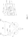
- FIG. 7 is a schematic diagram of reception according to an example of the present invention.
- FIG. 7 may be an example of FIG. 6 .
- Two TRPs TRP 1 -TRP 2 communicate with each other according to (e.g., via) a backhaul BHL.
- the TRP TRP 1 transmits a CORESET CRST 1 and a PDSCH layer group PLG 1 to a communication device CD
- the TRP TRP 2 transmits a PDSCH layer group PLG 2 to the communication device CD.
- the communication device CD includes Rx filters RF 1 -RF 2 .
- the Rx filter RF 1 belongs to a panel P 1 of the communication device CD
- the Rx filter RF 2 belongs to a panel P 2 of the communication device CD.
- the communication device CD is configured with correspondences between a TCI field (indicating TCI codepoints), TCI states, QCL parameter(s) and corresponding RSs according to the higher layer signaling.
- the communication device CD receives the CORESET CRST 1 for scheduling the PDSCH layer groups PLG 1 and PLG 2 from the TRP TRP 1 via the Rx filter RF 1 .
- X-axis represents a slot n for a time dimension “t” and Y-axis represents a frequency dimension “f”, wherein n is a non-negative integer.
- the communication CD device receives the PDSCH layer group PLG 1 according to the Rx filter RF 1 corresponding to the RS “A0”.
- the communication CD device receives the PDSCH layer group PLG 2 by determining (e.g., assuming) that at least one DM-RS port of the PDSCH layer group PLG 2 is QCLed with a RS “C0” with respect to the spatial QCL assumption associated with the second TCI state corresponding to the lowest codepoint “C0” of the TCI codepoints.
- the communication CD device receives the PDSCH layer group PLG 2 according to the Rx filter RF 2 corresponding to the RS “C0”.
- the first TCI state is determined according to (e.g., a first DCI in) a CORESET with the lowest CORESET ID in a slot.
- the first DCI (or the CORESET) is in the latest slot (e.g., from the slot the communication device is scheduled to receive the first PDSCH) in which at least one CORESET are monitored by the communication device.
- a offset between a first time instant for receiving the first DCI and a second time instant for receiving the first PDSCH is less than a threshold.
- the threshold is a time period for decoding the first DCI, e.g., 7, 14, or 28 OFDM symbols.
- the second TCI state is determined according to a TCI field.
- the TCI field is in a second DCI.
- the second DCI is for scheduling the second PDSCH.
- a offset between a third time instant for receiving the second DCI and a fourth time instant for receiving the second PDSCH is less than a threshold.
- the threshold is a time period for decoding the second DCI, e.g., 7, 14, or 28 OFDM symbols.
- the TCI field is configured according to (e.g., via) a higher layer signaling, e.g., a RRC signaling or a MAC CE signaling.
- FIG. 8 is a schematic diagram of reception according to an example of the present invention.
- FIG. 8 may be an example of FIG. 6 .
- Two TRPs TRP 1 -TRP 2 communicate with each other according to (e.g., via) a backhaul BHL.
- the TRP TRP 1 transmits a CORESET CRST 1 to a communication device CD
- the TRP TRP 2 transmits a CORESET CRST 2 and a PDSCH PSC 2 to the communication device CD.
- the communication device CD includes Rx filters RF 1 -RF 4 .
- the Rx filters RF 1 and RF 3 belong to a panel P 1 of the communication device CD
- the Rx filters RF 2 and RF 4 belong to a panel P 2 of the communication device CD.
- the communication device CD is configured with correspondences between a TCI field (indicating TCI codepoints), TCI states, QCL parameter(s) and corresponding RSs according to the higher layer signaling.
- the communication device CD receives the CORESET CRST 1 from the TRP TRP 1 , and receives the CORESET CRST 2 for scheduling the PDSCH PSC 2 from the TRP TRP 2 .
- X-axis represents a slot n for a time dimension “t” and Y-axis represents a frequency dimension “f”, wherein n is a non-negative integer.
- the communication device CD determines the Rx filter RF 1 according to a CORESET with the lowest CORESET ID in a slot n, i.e., the CORESET CRST 1 , and receives the CORESET CRST 1 according to the Rx filter RF 1 .
- the communication device CD determines the Rx filter RF 3 according to a CORESET for scheduling the PDSCH PSC 2 , i.e., the CORESET CRST 2 (e.g., a TCI state indicated by the lowest TCI codepoint in a TCI field.
- the communication device CD may assume that at least one DM-RS port of the PDSCH PSC 2 are QCLed with at least one RS in one of the TCI states with the lowest, the highest or a pre-defined TCI state ID, and receives the PDSCH PSC 2 according to the Rx filter RF 3 .
- FIG. 9 is a schematic diagram of reception according to an example of the present invention.
- Two TRPs TRP 1 -TRP 2 communicate with each other according to (e.g., via) a backhaul BHL.
- the TRP TRP 1 transmits a CORESET CRST 1 and a PDSCH PSC 1 to a communication device CD
- the TRP TRP 2 transmits a CORESET CRST 2 and a PDSCH PSC 2 to the communication device CD.
- the communication device CD includes Rx filters RF 1 -RF 4 .
- the Rx filters RF 1 and RF 3 belong to a panel P 1 of the communication device CD
- the Rx filters RF 2 and RF 4 belong to a panel P 2 of the communication device CD.
- the communication device CD receives the CORESET CRST 1 for scheduling the PDSCH PSC 1 from the TRP TRP 1 , and receives the CORESET CRST 2 for scheduling the PDSCH PSC 2 from the TRP TRP 2
- X-axis represents a slot n and a slot (n+1) for a time dimension “t” and Y-axis represents a frequency dimension “f”, wherein n is a non-negative integer. If a offset TO 1 between time instants for receiving the CORESET CRST 1 and receiving the PDSCH PSC 1 is less than a threshold TH for decoding the CORESET CRST 1 and a offset TO 2 between time instants for receiving the CORESET CRST 2 and receiving the PDSCH PSC 2 is greater than the threshold TH for decoding the CORESET CRST 2 , the communication device CD determines the Rx filter RF 1 according to a CORESET with the lowest CORESET ID in the slot n, i.e., the CORESET CRST 1 and receives the CORESET CRST 1 according to the Rx filter RF 1 .
- the communication device CD determines the Rx filter RF 3 according to a CORESET for scheduling the PDSCH PSC 2 , i.e., the CORESET CRST 2 (e.g., a TCI state indicated by the lowest N bits information in a TCI field. If the TCI codepoint of the TCI field indicates more than one TCI states, the communication device may assume that the at least one DM-RS port of the PDSCH are QCLed with at least one RS in one of the TCI states with the lowest, the highest or a pre-defined TCI state ID, and receives the PDSCH PSC 2 according to the Rx filter RF 3 .
- a CORESET for scheduling the PDSCH PSC 2
- the CORESET CRST 2 e.g., a TCI state indicated by the lowest N bits information in a TCI field. If the TCI codepoint of the TCI field indicates more than one TCI states, the communication device may assume that the at least one DM-RS port of the PD
- the second TCI state is determined according to a plurality of TCI states.
- the plurality of TCI states include the first TCI state and the second TCI state.
- the plurality of TCI states are configured according to (e.g., via) a higher layer signaling, e.g., a RRC signaling or a MAC CE signaling.
- the second TCI state is determined (e.g., selected) differently from the first TCI state, when a first plurality of Rx filters (e.g., a first panel of the communication device) to which the first Rx filter belongs is different from a second plurality of Rx filters (e.g., a second panel of the communication device) to which the second Rx filter belongs. That is, the first Rx filter and the second Rx filter belong to different plurality of Rx filters (e.g., different panels).
- a first plurality of Rx filters e.g., a first panel of the communication device
- second plurality of Rx filters e.g., a second panel of the communication device
- a first RS indicated by the first TCI state and a second RS indicated by the second TCI state are received simultaneously according to (e.g., via) a single spatial domain Rx filter, a plurality of simultaneous Rx filters (e.g., Rx filters), or different panels.
- FIG. 10 is a schematic diagram of reception according to an example of the present invention.
- Two TRPs TRP 1 -TRP 2 communicate with each other according to (e.g., via) a backhaul BHL.
- the TRP TRP 1 transmits a CORESET CRST 1 to a communication device CD
- the TRP TRP 2 transmits a CORESET CRST 2 and a PDSCH PSC 2 to the communication device CD.
- the communication device CD includes Rx filters RF 1 -RF 4 .
- the Rx filters RF 1 and RF 3 belong to a panel P 1 of the communication device CD
- the Rx filters RF 2 and RF 4 belong to a panel P 2 of the communication device CD.
- the communication device CD is configured with a plurality of TCI states TS including at least a first TCI state TS 1 and a second TCI state TS 2 . Similar to the scenario of FIG. 8 , a offset between time instants for receiving the CORESET CRST 2 and receiving the PDSCH PSC 2 is less than the threshold for decoding the CORESET CRST 2 .
- the communication device CD determines the Rx filter RF 1 according to a CORESET with the lowest CORESET ID in the slot n (e.g., the CORESET CRST 1 , and the first TCI state TS 1 is indicated in the CORESET CRST 1 ), and receives the CORESET CRST 1 according to the Rx filter RF 1 .
- the communication device CD determines the Rx filter RF 3 according to the second TCI state TS 2 , and receives the PDSCH PSC 2 according to the Rx filter RF 3 .
- the second TCI state TS 2 is determined (e.g., selected) from the plurality of TCI states TS and is determined (e.g., selected) differently from the first TCI state TS 1 , when the panel P 1 to which the Rx filter RF 1 belongs is different from the panel P 2 to which the Rx filter RF 3 belongs.
- the communication device CD determines the Rx filter RF 4 according to a CORESET with the lowest CORESET ID in the slot n (e.g., the CORESET CRST 1 and the first TCI state TS 1 is indicated in the CORESET CRST 1 ), and receives the CORESET CRST 1 according to the Rx filter RF 4 .
- the communication device CD determines the Rx filter RF 1 according to the second TCI state TS 2 , and receives the PDSCH PSC 2 according to the Rx filter RF 1 .
- the second TCI state TS 2 is determined (e.g., selected) from the plurality of TCI states TS and is determined (e.g., selected) differently from the first TCI state TS 1 , when the panel P 2 to which the Rx filter RF 4 belongs is different from the panel P 1 to which the Rx filter RF 1 belongs.
- the first TCI state and the second TCI state are configured in a CORESET, e.g., a CORESET with the lowest CORESET ID.
- the communication device determines a first Rx filter corresponding to (e.g., a RS of) the first TCI state, and receives at least one CORESET (e.g., the CORESET) according to (e.g., via) the first Rx filter.
- the communication device determines a second Rx filter corresponding to (e.g., a RS of) the second TCI state, and receives at least one PDSCH according to (e.g., via) the second Rx filter.
- the communication device receives an indicator, and determines whether the second TCI state is activated or presented according to the indicator. For example, the communication device determines that the second TCI state is activated or presented in the CORESET, if the indicator indicating “1”. For example, the communication device determines that the second TCI state is deactivated or presented in the CORESET, if the indicator indicating “0”.
- FIG. 11 is a schematic diagram of a schematic diagram of a CORESET-TCI state mapping table 110 according to an example of the present invention.
- FIG. 11 follows the scenario of FIG. 8 .
- a communication device is configured with a CORESET CRST with the lowest CORESET ID, i.e., “CRST 1 ”
- a first TCI state is corresponding to a TCI state “A0” (e.g., for a spatial QCL assumption)
- a second TCI state is corresponding to a TCI state “C0” (e.g., for the spatial QCL assumption).
- the communication device determines (e.g., to use) a first Rx filter corresponding to (e.g., a RS of) the TCI state “A0”, and receives the CORESET CRST 1 and/or the CORESET CRST 2 according to (e.g., via) the first Rx filter.
- the communication device determines (e.g., to use) a second Rx filter corresponding to (e.g., a RS of) the TCI state “C0”, and receives the PDSCH PSC 2 according to (e.g., via) the second Rx filter.
- FIG. 12 is a flowchart of a process 120 according to an example of the present invention.
- the process 120 may be utilized in a communication device (e.g., the communication device shown in FIG. 1 ), to handle a reception.
- the process 120 may be compiled into the program codes 214 and includes the following steps:
- Step 1200 Start.
- Step 1202 Receive a DCI from a CORESET.
- Step 1204 Receive a PDSCH according to the DCI, wherein the CORESET is configured with a CORESET pool index.
- Step 1206 End.
- the communication device receives a DCI from a CORESET (e.g., of a serving cell, which may belong to the TRP TRP 1 or the TRP TPR 2 in FIG. 1 ).
- the communication device receives (e.g., decodes) a PDSCH according to the DCI.
- the CORESET is configured with a CORESET pool index.
- Realization of the process 120 is not limited to the above description. The following examples may be applied for realizing the process 120 .
- the communication device determines (e.g., calculates, obtains, selects and/or generates) a Rx filter according to the CORESET pool index, and receives the PDSCH according to (e.g., via) the Rx filter.
- the communication device receives the PDSCH by determining (e.g., assuming) that at least one DM-RS port of the PDSCH is QCLed with at least one RS with respect to at least one QCL parameter (e.g., spatial, time or frequency QCL assumption) used for physical DL control channel (PDCCH) QCL indication of a CORESET with the lowest CORESET ID among at least one CORESET, wherein the at least one CORESET is configured with the same value of another CORESET pool index.
- the another CORESET pool index and the CORESET pool index described in the process 120 may be the same or different.
- the DCI (or the CORESET) is in the latest slot (e.g., from the slot the communication device is scheduled to receive the PDSCH) in which the at least one CORESET are monitored by the communication device.
- the CORESET with the lowest CORESET ID is the same as or different from different from the CORESET configured with the CORESET pool index described in the process 120 .
- the CORESET pool index is associated with at least one of a Rx filter, a TRP, a PDCCH configuration, a scrambling ID and a cell.
- the CORESET group configured with the CORESET pool index is transmitted from the associated TRP.
- the CORESET pool index indicates a CORESET group.
- the CORESET group includes at least one CORESET.
- a offset (e.g., a time offset) between a first time instant for receiving the DCI and a second time instant for receiving the PDSCH is less than a threshold.
- the offset is indicated according to (e.g., by using) the DCI.
- the threshold is configured according to (e.g., via) a higher layer signaling, e.g., a RRC signaling or a MAC CE signaling.
- the threshold is a time period for decoding the DCI.
- the threshold includes (e.g., is) at least one OFDM symbol, e.g., 7, 14, or 28 OFDM symbols.
- the CORESET is configured according to (e.g., via) a higher layer signaling, e.g., a RRC signaling or a MAC CE signaling.
- a higher layer signaling e.g., a RRC signaling or a MAC CE signaling.
- FIG. 13 is a schematic diagram of reception according to an example of the present invention.
- Two TRPs TRP 1 -TRP 2 communicate with each other according to (e.g., via) a backhaul BHL.
- the communication device CD includes Rx filters RF 1 -RF 4 .
- the Rx filters RF 1 and RF 2 belong to a panel P 1 of the communication device CD, and the Rx filters RF 3 and RF 4 belong to a panel P 2 of the communication device CD.
- the communication device CD receives (e.g., is configured with) CORESETs CRST 1 , CRST 2 , CRST 3 and CRST 4 .
- the CORESET CRST 2 and CRST 4 are configured with the same value of a CORESET pool index, i.e., “CG 2 ”.
- the CORESET CRST 1 and CRST 3 are configured with the same value of a CORESET pool index, i.e., “CG 1 ”. Similar to the scenario of FIG. 8 , a offset TO between time instants for receiving the CORESET CRST 2 and receiving a PDSCH PSC 2 is less than a threshold TH for decoding the CORESET CRST 2 , or similar to the scenario of FIG.
- a offset TO 1 between time instants for receiving the CORESET CRST 1 and receiving a PDSCH PSC 1 is less than a threshold TH for decoding the CORESET CRST 1 and a offset TO 2 between time instants for receiving the CORESET CRST 2 and receiving the PDSCH PSC 2 is greater than the threshold TH for decoding the CORESET CRST 2 .
- the communication device CD receives a DCI from the CORESET CRST 2 , and receives the PDSCH PSC 2 according to the DCI.
- the communication device CD receives the PDSCH PSC 2 by determining (e.g., assuming) that at least one DM-RS port of the PDSCH PSC 2 are QCLed with at least one RS with respect to QCL parameter(s) used for PDCCH QCL indication of a CORESET with the lowest CORESET ID (e.g., CORESET CRST 2 ) among at least one CORESET (e.g., the CORESETs CRST 2 and CRST 4 ), wherein the at least one CORESET are configured with the same value of the CORESET pool index (e.g., “CG 2 ”).
- the communication device CD may receive the PDSCH PSC 2 according to (e.g., via) the Rx filter RF 3 corresponding to the CORESET pool index, i.e., “CG 2 ”.
- the communication device CD receives the PDSCH PSC 1 by determining (e.g., assuming) that at least one DM-RS port of the PDSCH PSC 1 are QCLed with at least one RS with respect to QCL parameter(s) used for PDCCH QCL indication of a CORESET with the lowest CORESET ID (e.g., CORESET CRST 1 ) among at least one CORESET (e.g., the CORESETs CRST 1 and CRST 3 ), wherein the at least one CORESET are configured with the same value of the CORESET pool index (e.g., “CG 1 ”).
- the communication device CD may receive the PDSCH PSC 1 according to (e.g., via) the Rx filter RF 1 corresponding to the C
- FIG. 14 is a schematic diagram of a reporting before a reception according to an example of the present invention.
- Two TRPs TRP 1 -TRP 2 communicate with each other according to (e.g., via) a backhaul BHL.
- the TRP TRP 1 transmits (e.g., beamforms) CSI-RSs CSI-RS 1 -CSI-RS 14 to a communication device CD
- the TRP TRP 2 transmits (e.g., beamforms) CSI-RSs CSI-RS 5 -CSI-RS 8 to the communication device CD.
- the communication device CD includes Rx filters RF 1 -RF 2 .
- the Rx filter RF 1 belongs to a panel P 1 of the communication device CD
- the Rx filter RF 2 belongs to a panel P 2 of the communication device CD.
- the communication device CD measures the CSI-RSs CSI-RS 1 -CSI-RS 4 according to (e.g., by using) the Rx filter RF 1
- the communication device CD reports the CSI-RS CSI-RS 3 with a panel index of the panel P 1 (e.g., “P 1 ”) and the CSI-RS CSI-RS 4 with “P 1 ” to the TRP TRP 1 , and reports the CSI-RS CSI-RS 5 with a panel index of the panel P 2 (e.g., “P 2 ”) and the CSI-RS CSI-RS 6 with “P 2 ” to the TRP TRP 2 .
- the TRP TRP 1 obtains that the CSI-RSs CSI-RS 3 and CSI-RS 4 are received via the same panel and cannot be received simultaneously.
- the TRP TRP 2 obtains that the CSI-RSs CSI-RS 5 and CSI-RS 6 are received via the same panel and cannot be received simultaneously.
- FIG. 15 is a schematic diagram of a reporting before a reception according to an example of the present invention.
- Two TRPs TRP 1 -TRP 2 communicate with each other according to (e.g., via) a backhaul BHL.
- the TRP TRP 1 transmits (e.g., beamforms) a CORESET CRST and CSI-RSs CSI-RS 1 and CSI-RS 2 to a communication device CD.
- the TRP TRP 2 transmits (e.g., beamforms) CSI-RSs CSI-RS 3 and CSI-RS 4 to the communication device CD.
- the communication device CD includes Rx filters RF 1 -RF 2 .
- the communication device CD measures the CSI-RSs CSI-RS 1 and CSI-RS 2 according to (e.g., by using) the Rx filter RF 1 , and measures the CSI-RSs CSI-RS 3 and CSI-RS 4 according to according to (e.g., by using) the Rx filter RF 2 . Then, the communication device CD reports the CSI-RS CSI-RS 2 with a one-bit flag “1” to the TRP TRP 1 , and reports the CSI-RS CSI-RS 3 with a one-bit flag “0” to the TRP TRP 2 .
- the TRP TRP 1 and/or the TRP TRP 2 obtains that the CSI-RS CSI-RS 2 is received via a Rx filter determined according to (i.e., is QCLed with a RS in) a preconfigured/fixed TCI state indicated in the CORESET CRST. That is, the Rx filter for receiving the CSI-RS CSI-RS 2 is the same as the Rx filter for receiving the CORESET CRST.
- the TRP TRP 1 and/or the TRP TRP 2 obtains that the CSI-RS CSI-RS 3 is not received via the Rx filter determined according to (i.e., is not QCLed with a RS in) the preconfigured/fixed TCI state indicated in the CORESET CRST. That is, the Rx filter for receiving the CSI-RS CSI-RS 2 is different from the Rx filter for receiving the CORESET CRST.
- FIG. 16 is a schematic diagram of a reporting before a reception according to an example of the present invention.
- Two TRPs TRP 1 -TRP 2 communicate with each other according to (e.g., via) a backhaul BHL.
- the TRP TRP 1 transmits (e.g., beamforms) CSI-RSs CSI-RS 1 -CSI-RS 4 to a communication device CD
- the TRP TRP 2 transmits (e.g., beamforms) CSI-RSs CSI-RS 5 -CSI-RS 8 to the communication device CD.
- the communication device CD includes Rx filters RF 1 -RF 4 .
- the Rx filters RF 1 and RF 2 belong to a panel P 1 of the communication device CD, and the Rx filters RF 3 and RF 4 belong to a panel P 2 of the communication device CD.
- the communication device CD measures CSI-RSs CSI-RS 1 -CSI-RS 4 according to (e.g., by using) the Rx filter RF 1 , and measures CSI-RSs CSI-RS 5 -CSI-RS 8 according to (e.g., by using) the Rx filter RF 2 .
- the communication device CD reports the CSI-RSs CSI-RS 3 and CSI-RS 4 in a first group CRG 1 to the TRP TRP 1 , and reports the CSI-RS CSI-RS 5 and CSI-RS 6 in a second group CRG 2 to the TRP TRP 2 , wherein the CSI-RSs CSI-RS 3 and CSI-RS 4 in the first group CRG 1 may not be received simultaneously and the CSI-RSs CSI-RS 5 and CSI-RS 6 in the second group CRG 2 may not be received simultaneously. That is, CSI-RSs in the same group not be received simultaneously, and CSI-RSs in different groups may be received simultaneously.
- FIG. 17 is a schematic diagram of a reporting before a reception according to an example of the present invention.
- Two TRPs TRP 1 -TRP 2 communicate with each other via according to (e.g., via) a backhaul BHL.
- the TRP TRP 1 transmits (e.g., beamforms) CSI-RSs CSI-RS 1 -CSI-RS 4 to a communication device CD
- the TRP TRP 2 transmits (e.g., beamforms) CSI-RSs CSI-RS 5 -CSI-RS 8 to the communication device CD.
- the communication device CD includes Rx filters RF 1 -RF 4 .
- the Rx filters RF 1 and RF 2 belong to a panel P 1 of the communication device CD, and the Rx filters RF 3 and RF 4 belong to a panel P 2 of the communication device CD.
- the communication device CD is configured to perform two measurement reports according to two measurement configurations MC 1 and MC 2 , wherein the measurement configuration MC 1 is for measuring the CSI-RSs CSI-RS 1 -CSI-RS 4 and the measurement configuration MC 2 is for measuring the CSI-RSs CSI-RS 5 -CSI-RS 8 .
- the communication device CD measures the CSI-RSs CSI-RS 1 -CSI-RS 4 according to the measurement configuration MC 1 according to (e.g., by using) the Rx filter RF 1 , and measures CSI-RSs CSI-RS 5 -CSI-RS 8 according to the measurement configuration MC 2 according to (e.g., by using) the Rx filter RF 1 . Then, the communication device CD reports the CSI-RSs CSI-RS 3 and CSI-RS 4 in a first report to the TRP TRP 1 , and reports the CSI-RS CSI-RS 5 and CSI-RS 6 in a second report to the TRP TRP 2 .
- the communication device CD determines that CSI-RSs in different reports (e.g., the CSI-RSs CSI-RS 3 and CSI-RS 6 , or the CSI-RSs CSI-RS 4 and CSI-RS 5 ) may be received simultaneously.
- CSI-RSs in different reports e.g., the CSI-RSs CSI-RS 3 and CSI-RS 6 , or the CSI-RSs CSI-RS 4 and CSI-RS 5 .
- the TRP may be replaced by a cell, a serving cell, an unlicensed cell, an unlicensed serving cell, an unlicensed TRP, a gNB, an eNB, but is not limited herein.
- the Rx filter may be replaced by a spatial Rx filter, a Rx beam, a spatial Rx parameter, a spatial domain Rx filter, but is not limited herein.
- the beam may be replaced by an antenna, an antenna port, an antenna element, a group of antennas, a group of antenna ports, a group of antenna elements, a spatial domain filter, a reference signal resource, but is not limited herein.
- a beam may be represented by an antenna port, a group of antenna ports or a spatial domain filter.
- the operation of “determine” or “assume” described above may be replaced by the operation of “compute”, “calculate”, “obtain”, “generate”, “output, “use”, “choose/select” or “decide”.
- the operation of “transmit” described above may be replaced by the operation of “beamform” or “signal”.
- the term of “according to” described above may be replaced by “via” or “by using”.
- the term of “via” described above may be replaced by “on”, “in” or “at”.
- the phrase of “corresponding to” described above may be replaced by “of” or “associated with”.
- Examples of the hardware may include analog circuit(s), digital circuit (s) and/or mixed circuit (s).
- the hardware may include ASIC(s), field programmable gate array(s) (FPGA(s)), programmable logic device(s), coupled hardware components or combination thereof.
- the hardware may include general-purpose processor(s), microprocessor(s), controller(s), digital signal processor(s) (DSP(s)) or combination thereof.
- Examples of the software may include set(s) of codes, set(s) of instructions and/or set(s) of functions retained (e.g., stored) in a storage unit, e.g., a computer-readable medium.
- the computer-readable medium may include SIM, ROM, flash memory, RAM, CD-ROM/DVD-ROM/BD-ROM, magnetic tape, hard disk, optical data storage device, non-volatile storage unit, or combination thereof.
- the computer-readable medium (e.g., storage unit) may be coupled to at least one processor internally (e.g., integrated) or externally (e.g., separated).
- the at least one processor which may include one or more modules may (e.g., be configured to) execute the software in the computer-readable medium.
- the set(s) of codes, the set(s) of instructions and/or the set(s) of functions may cause the at least one processor, the module(s), the hardware and/or the electronic system to perform the related steps.
- Examples of the electronic system may include a system on chip (SoC), system in package (SiP), a computer on module (CoM), a computer program product, an apparatus, a mobile phone, a laptop, a tablet computer, an electronic book or a portable computer system, and the communication device 20 .
- SoC system on chip
- SiP system in package
- CoM computer on module
- a computer program product an apparatus, a mobile phone, a laptop, a tablet computer, an electronic book or a portable computer system, and the communication device 20 .
- the present invention provides a communication device and method for handling a reception.
- the communication device knows how to receive the signal from the TRPs. As a result, efficiency of resource utilization is improved.
Landscapes
- Engineering & Computer Science (AREA)
- Signal Processing (AREA)
- Computer Networks & Wireless Communication (AREA)
- Physics & Mathematics (AREA)
- General Physics & Mathematics (AREA)
- Mobile Radio Communication Systems (AREA)
- Financial Or Insurance-Related Operations Such As Payment And Settlement (AREA)
- Circuits Of Receivers In General (AREA)
- Input Circuits Of Receivers And Coupling Of Receivers And Audio Equipment (AREA)
- Quality & Reliability (AREA)
- Electromagnetism (AREA)
Priority Applications (9)
| Application Number | Priority Date | Filing Date | Title |
|---|---|---|---|
| US16/989,847 US11284385B2 (en) | 2019-08-13 | 2020-08-10 | Device and method for handling a reception |
| TW109127212A TWI768429B (zh) | 2019-08-13 | 2020-08-11 | 處理接收的裝置及方法 |
| EP20190440.6A EP3780471A1 (en) | 2019-08-13 | 2020-08-11 | Device and method for handling a reception |
| JP2020136774A JP2021035056A (ja) | 2019-08-13 | 2020-08-13 | 受信を処理するためのデバイスおよび方法 |
| AU2020217415A AU2020217415B9 (en) | 2019-08-13 | 2020-08-13 | Device and method for handling a reception |
| CN202010810947.4A CN112399604B (zh) | 2019-08-13 | 2020-08-13 | 处理接收的装置及方法 |
| KR1020200101736A KR102443683B1 (ko) | 2019-08-13 | 2020-08-13 | 수신을 처리하기 위한 기기 및 방법 |
| AU2021215290A AU2021215290B2 (en) | 2019-08-13 | 2021-08-13 | Device and method for handling a reception |
| KR1020220114373A KR102553791B1 (ko) | 2019-08-13 | 2022-09-08 | 수신을 처리하기 위한 기기 및 방법 |
Applications Claiming Priority (2)
| Application Number | Priority Date | Filing Date | Title |
|---|---|---|---|
| US201962885831P | 2019-08-13 | 2019-08-13 | |
| US16/989,847 US11284385B2 (en) | 2019-08-13 | 2020-08-10 | Device and method for handling a reception |
Publications (2)
| Publication Number | Publication Date |
|---|---|
| US20210051635A1 US20210051635A1 (en) | 2021-02-18 |
| US11284385B2 true US11284385B2 (en) | 2022-03-22 |
Family
ID=72046729
Family Applications (1)
| Application Number | Title | Priority Date | Filing Date |
|---|---|---|---|
| US16/989,847 Active 2040-11-03 US11284385B2 (en) | 2019-08-13 | 2020-08-10 | Device and method for handling a reception |
Country Status (7)
| Country | Link |
|---|---|
| US (1) | US11284385B2 (zh) |
| EP (1) | EP3780471A1 (zh) |
| JP (1) | JP2021035056A (zh) |
| KR (2) | KR102443683B1 (zh) |
| CN (1) | CN112399604B (zh) |
| AU (2) | AU2020217415B9 (zh) |
| TW (1) | TWI768429B (zh) |
Families Citing this family (8)
| Publication number | Priority date | Publication date | Assignee | Title |
|---|---|---|---|---|
| US20220322410A1 (en) * | 2019-08-08 | 2022-10-06 | Ntt Docomo, Inc. | Terminal and radio communication method |
| US11910416B2 (en) * | 2019-10-11 | 2024-02-20 | Qualcomm Incorporated | Default quasi-colocation for single downlink control information-based multiple transmission reception points |
| US20230069777A1 (en) * | 2020-03-16 | 2023-03-02 | Lg Electronics Inc. | Method and device for transmitting/receiving signal on basis of spatial parameters in wireless communication system |
| US20240205695A1 (en) * | 2021-04-13 | 2024-06-20 | Telefonaktiebolaget Lm Ericsson (Publ) | Common spatial filter updates for multi-downlink control information (dci) based multi-transmission reception point (trp) systems |
| US20230022602A1 (en) * | 2021-07-20 | 2023-01-26 | Samsung Electronics Co., Ltd. | Methods and apparatuses for tci state indication in a wireless communications system |
| WO2023132071A1 (ja) * | 2022-01-07 | 2023-07-13 | 株式会社Nttドコモ | 端末、無線通信方法及び基地局 |
| US20230309112A1 (en) * | 2022-03-23 | 2023-09-28 | Samsung Electronics Co., Ltd. | Method and apparatus for dci based dynamic beam indication |
| WO2023195779A1 (ko) * | 2022-04-07 | 2023-10-12 | 엘지전자 주식회사 | 무선 통신 시스템에서 상향링크 송수신 방법 및 그 장치 |
Citations (11)
| Publication number | Priority date | Publication date | Assignee | Title |
|---|---|---|---|---|
| US20180343653A1 (en) | 2017-05-26 | 2018-11-29 | Samsung Electronics Co., Ltd. | Method and apparatus for beam indication in next generation wireless systems |
| US20190037540A1 (en) | 2016-03-16 | 2019-01-31 | Lg Electronics Inc. | Method for transmitting and receiving control information in wireless communication system, and apparatus therefor |
| US20190141693A1 (en) | 2017-11-08 | 2019-05-09 | Samsung Electronics Co., Ltd | Method and apparatus for beam management in the unlicensed spectrum |
| WO2019099659A1 (en) | 2017-11-15 | 2019-05-23 | Idac Holdings, Inc. | Beam management in a wireless network |
| US20190222289A1 (en) * | 2018-01-12 | 2019-07-18 | Qualcomm Incorporated | Transmission configuration indication based beam switching |
| US20190239093A1 (en) | 2018-03-19 | 2019-08-01 | Intel Corporation | Beam indication information transmission |
| US20190246395A1 (en) | 2018-02-07 | 2019-08-08 | Asustek Computer Inc. | Method and apparatus for monitoring for interrupted transmission indication in a wireless communication system |
| US20190260532A1 (en) * | 2018-02-16 | 2019-08-22 | Qualcomm Incorporated | Transmission configuration indication states with quasi-collocation groups |
| US20200045672A1 (en) * | 2017-09-15 | 2020-02-06 | Guangdong Oppo Mobile Telecommunications Corp., Ltd | Data Transmission Method, Network Device, and Terminal Device |
| US20200107352A1 (en) * | 2018-09-27 | 2020-04-02 | Mediatek Inc. | Enhancements on qcl frameworks for multiple trp operation |
| US20200221432A1 (en) * | 2019-01-07 | 2020-07-09 | Qualcomm Incorporated | Scrambling sequence generation for a multi-transmit receive point configuration |
Family Cites Families (7)
| Publication number | Priority date | Publication date | Assignee | Title |
|---|---|---|---|---|
| KR102164967B1 (ko) * | 2017-01-06 | 2020-10-13 | 한국전자통신연구원 | 통신 시스템에서 제어 채널의 송수신 방법 및 장치 |
| US10383142B2 (en) * | 2017-01-13 | 2019-08-13 | Acer Incorporated | Device and method of handling channel status information reports for transmission time intervals |
| WO2019097478A1 (en) * | 2017-11-16 | 2019-05-23 | Telefonaktiebolaget Lm Ericsson (Publ) | Configuring spatial qcl reference in a tci state |
| EP3740014A4 (en) * | 2018-01-11 | 2021-09-08 | Ntt Docomo, Inc. | USER TERMINAL DEVICE AND WIRELESS COMMUNICATION PROCEDURE |
| CN110049561B (zh) * | 2018-01-16 | 2023-03-28 | 华硕电脑股份有限公司 | 不连续传送指示的准共址关联指示的方法和设备 |
| CN108199819A (zh) * | 2018-02-26 | 2018-06-22 | 中兴通讯股份有限公司 | 控制信令的发送、接收以及信息的确定方法及装置 |
| US20220322410A1 (en) * | 2019-08-08 | 2022-10-06 | Ntt Docomo, Inc. | Terminal and radio communication method |
-
2020
- 2020-08-10 US US16/989,847 patent/US11284385B2/en active Active
- 2020-08-11 TW TW109127212A patent/TWI768429B/zh active
- 2020-08-11 EP EP20190440.6A patent/EP3780471A1/en active Pending
- 2020-08-13 KR KR1020200101736A patent/KR102443683B1/ko active IP Right Grant
- 2020-08-13 AU AU2020217415A patent/AU2020217415B9/en active Active
- 2020-08-13 JP JP2020136774A patent/JP2021035056A/ja active Pending
- 2020-08-13 CN CN202010810947.4A patent/CN112399604B/zh active Active
-
2021
- 2021-08-13 AU AU2021215290A patent/AU2021215290B2/en active Active
-
2022
- 2022-09-08 KR KR1020220114373A patent/KR102553791B1/ko active IP Right Grant
Patent Citations (11)
| Publication number | Priority date | Publication date | Assignee | Title |
|---|---|---|---|---|
| US20190037540A1 (en) | 2016-03-16 | 2019-01-31 | Lg Electronics Inc. | Method for transmitting and receiving control information in wireless communication system, and apparatus therefor |
| US20180343653A1 (en) | 2017-05-26 | 2018-11-29 | Samsung Electronics Co., Ltd. | Method and apparatus for beam indication in next generation wireless systems |
| US20200045672A1 (en) * | 2017-09-15 | 2020-02-06 | Guangdong Oppo Mobile Telecommunications Corp., Ltd | Data Transmission Method, Network Device, and Terminal Device |
| US20190141693A1 (en) | 2017-11-08 | 2019-05-09 | Samsung Electronics Co., Ltd | Method and apparatus for beam management in the unlicensed spectrum |
| WO2019099659A1 (en) | 2017-11-15 | 2019-05-23 | Idac Holdings, Inc. | Beam management in a wireless network |
| US20190222289A1 (en) * | 2018-01-12 | 2019-07-18 | Qualcomm Incorporated | Transmission configuration indication based beam switching |
| US20190246395A1 (en) | 2018-02-07 | 2019-08-08 | Asustek Computer Inc. | Method and apparatus for monitoring for interrupted transmission indication in a wireless communication system |
| US20190260532A1 (en) * | 2018-02-16 | 2019-08-22 | Qualcomm Incorporated | Transmission configuration indication states with quasi-collocation groups |
| US20190239093A1 (en) | 2018-03-19 | 2019-08-01 | Intel Corporation | Beam indication information transmission |
| US20200107352A1 (en) * | 2018-09-27 | 2020-04-02 | Mediatek Inc. | Enhancements on qcl frameworks for multiple trp operation |
| US20200221432A1 (en) * | 2019-01-07 | 2020-07-09 | Qualcomm Incorporated | Scrambling sequence generation for a multi-transmit receive point configuration |
Non-Patent Citations (14)
| Title |
|---|
| 3GPP TS 38.214 V15.6.0 (Jun. 2019); 3rd Generation Partnership Project; Technical Specification Group Radio Access Network; NR; Physical layer procedures for data (Release 15), pp. 1-105, Jun. 2019. |
| 3GPP TS 38.321 V15.6.0 (Jun. 2019); 3rd Generation Partnership Project; Technical Specification Group Radio Access Network; NR; Medium Access Control (MAC) protocol specification (Release 15), pp. 1-77, Jun. 2019. |
| Huawei, Hisilicon, Remaining details for DL design on multi-TRP/panel transmission for eMBB, 3GPP TSG RAN WG1 #97, Reno, USA, May 13-17, 2019, R1-1906040, XP051727497. |
| Huawei, Hisilicon, Single NR-PDCCH based non-coherent JT in Rel-15, 3GPP TSG RAN WG1 NR Ad Hoc Meeting#4, Vancouver, Canada, Jan. 22-26, 2017, R1-1800530, XP051384908. |
| HUAWEI, HISILICON: "Remaining details for DL design on multi-TRP/panel transmission for eMBB", 3GPP DRAFT; R1-1906040, 3RD GENERATION PARTNERSHIP PROJECT (3GPP), MOBILE COMPETENCE CENTRE ; 650, ROUTE DES LUCIOLES ; F-06921 SOPHIA-ANTIPOLIS CEDEX ; FRANCE, vol. RAN WG1, no. Reno, USA; 20190513 - 20190517, R1-1906040, 13 May 2019 (2019-05-13), Mobile Competence Centre ; 650, route des Lucioles ; F-06921 Sophia-Antipolis Cedex ; France , XP051727497 |
| HUAWEI, HISILICON: "Single NR-PDCCH based non-coherent JT in Rel-15", 3GPP DRAFT; R1-1800530, 3RD GENERATION PARTNERSHIP PROJECT (3GPP), MOBILE COMPETENCE CENTRE ; 650, ROUTE DES LUCIOLES ; F-06921 SOPHIA-ANTIPOLIS CEDEX ; FRANCE, vol. RAN WG1, no. Vancouver, Canada; 20170122 - 20170126, R1-1800530, 13 January 2018 (2018-01-13), Mobile Competence Centre ; 650, route des Lucioles ; F-06921 Sophia-Antipolis Cedex ; France , XP051384908 |
| Intel Corporation, Summary for simultaneous Tx and Rx of channels and RS, 3GPP TSG RAN WG1 Meeting #95, Spokane, USA, Nov. 12-16, 2018, pp. 1/10-10/10, R1-1813896, XP051494400. |
| INTEL CORPORATION: "Summary for simultaneous Tx and Rx of channels and RS", 3GPP DRAFT; R1-1813896_SUMMARY, 3RD GENERATION PARTNERSHIP PROJECT (3GPP), MOBILE COMPETENCE CENTRE ; 650, ROUTE DES LUCIOLES ; F-06921 SOPHIA-ANTIPOLIS CEDEX ; FRANCE, vol. RAN WG1, no. Spokane, USA; 20181112 - 20181116, R1-1813896_summary, 14 November 2018 (2018-11-14), Mobile Competence Centre ; 650, route des Lucioles ; F-06921 Sophia-Antipolis Cedex ; France , XP051494400 |
| Mediatek Inc., Enhancements on multi-TRP/panel transmission, 3GPP TSG RAN WG1 Meeting #95, Spokane, USA, Nov. 12-16, 2018, R1-1812349, XP051478542. |
| MEDIATEK INC.: "Enhancements on multi-TRP/panel transmission", 3GPP DRAFT; R1-1812349 ENHANCEMENTS ON MULTI-TRPPANEL TRANSMISSION, 3RD GENERATION PARTNERSHIP PROJECT (3GPP), MOBILE COMPETENCE CENTRE ; 650, ROUTE DES LUCIOLES ; F-06921 SOPHIA-ANTIPOLIS CEDEX ; FRANCE, vol. RAN WG1, no. Spokane, USA; 20181112 - 20181116, R1-1812349 Enhancements on multi-TRPpanel transmis, 3 November 2018 (2018-11-03), Mobile Competence Centre ; 650, route des Lucioles ; F-06921 Sophia-Antipolis Cedex ; France , XP051478542 |
| Oppo, Enhancements on multi-TRP and multi-panel transmission, 3GPP TSG RAN WG1 Meeting #97, R1-1906287, Reno, USA, May 13-17, 2019. |
| Qualcomm Incorporated, Details on simultaneous reception/transmission of PHY channels and RS in FR2, 3GPP TSG RAN WG1 Meeting #94bis, Chengdu, China, Oct. 8-12, 2018, R1-1811233, XP051518634. |
| QUALCOMM INCORPORATED: "Details on simultaneous reception/transmission of PHY channels and RS in FR2", 3GPP DRAFT; R1-1811233, 3RD GENERATION PARTNERSHIP PROJECT (3GPP), MOBILE COMPETENCE CENTRE ; 650, ROUTE DES LUCIOLES ; F-06921 SOPHIA-ANTIPOLIS CEDEX ; FRANCE, R1-1811233, 29 September 2018 (2018-09-29), Mobile Competence Centre ; 650, route des Lucioles ; F-06921 Sophia-Antipolis Cedex ; France , pages 1 - 4, XP051518634 |
| ZTE, Enhancements on Multi-TRP and Multi-panel Transmission, Agenda item 7.2.8.2, 3GPP TSG RAN WG1 #97, R1-1906236, Reno, USA, May 13-17, 2019. |
Also Published As
| Publication number | Publication date |
|---|---|
| AU2020217415B2 (en) | 2021-09-09 |
| TWI768429B (zh) | 2022-06-21 |
| AU2020217415B9 (en) | 2021-10-21 |
| CN112399604A (zh) | 2021-02-23 |
| AU2021215290A1 (en) | 2021-09-02 |
| AU2021215290B2 (en) | 2023-01-12 |
| TW202107917A (zh) | 2021-02-16 |
| KR20220129516A (ko) | 2022-09-23 |
| US20210051635A1 (en) | 2021-02-18 |
| CN112399604B (zh) | 2023-08-08 |
| EP3780471A1 (en) | 2021-02-17 |
| KR20210020827A (ko) | 2021-02-24 |
| AU2020217415A1 (en) | 2021-03-04 |
| JP2021035056A (ja) | 2021-03-01 |
| KR102553791B1 (ko) | 2023-07-07 |
| KR102443683B1 (ko) | 2022-09-14 |
Similar Documents
| Publication | Publication Date | Title |
|---|---|---|
| US11284385B2 (en) | Device and method for handling a reception | |
| US10383142B2 (en) | Device and method of handling channel status information reports for transmission time intervals | |
| US11172543B2 (en) | Device and method of handling physical downlink shared channels in bandwidth parts | |
| CN113924754B (zh) | 非均匀解调参考信号捆绑 | |
| US20200322901A1 (en) | Device and Method of Handling Power Headroom Report for Multiple Time Intervals | |
| KR102702190B1 (ko) | 사운딩 참조 신호를 사용하여 업링크 송신을 처리하는 기기 및 방법 | |
| WO2020132289A1 (en) | Beam switching robustness in unlicensed radio frequency spectrum band | |
| US11159290B2 (en) | Device and method for handling a sounding reference signal transmission | |
| CN117941276A (zh) | 用于多个面板用户设备的信道状态信息报告 | |
| US9867061B2 (en) | Method of handling measurement pattern for TDD system and related communication device | |
| US20230042313A1 (en) | Device and Method for Handling a Hybrid Automatic Repeat Request Transmission | |
| US20170272981A1 (en) | Device and Method of Handling Transmission in Unlicensed Band | |
| AU2022215252B2 (en) | Device and method for handling a reference signal reporting | |
| US10085241B2 (en) | Device of reporting control information | |
| AU2023201831A1 (en) | Device and method for handling a multi-cell scheduling |
Legal Events
| Date | Code | Title | Description |
|---|---|---|---|
| AS | Assignment |
Owner name: ACER INCORPORATED, TAIWAN Free format text: ASSIGNMENT OF ASSIGNORS INTEREST;ASSIGNORS:LO, LI-CHUNG;LEE, CHIEN-MIN;REEL/FRAME:053450/0698 Effective date: 20200805 |
|
| FEPP | Fee payment procedure |
Free format text: ENTITY STATUS SET TO UNDISCOUNTED (ORIGINAL EVENT CODE: BIG.); ENTITY STATUS OF PATENT OWNER: LARGE ENTITY |
|
| STPP | Information on status: patent application and granting procedure in general |
Free format text: DOCKETED NEW CASE - READY FOR EXAMINATION |
|
| STPP | Information on status: patent application and granting procedure in general |
Free format text: NOTICE OF ALLOWANCE MAILED -- APPLICATION RECEIVED IN OFFICE OF PUBLICATIONS |
|
| STCF | Information on status: patent grant |
Free format text: PATENTED CASE |