US11280195B2 - Single-anchor centrally grouted full-length anchored steel wire bundle and supporting method thereof - Google Patents

Single-anchor centrally grouted full-length anchored steel wire bundle and supporting method thereof Download PDF

Info

Publication number
US11280195B2
US11280195B2 US16/624,541 US201816624541A US11280195B2 US 11280195 B2 US11280195 B2 US 11280195B2 US 201816624541 A US201816624541 A US 201816624541A US 11280195 B2 US11280195 B2 US 11280195B2
Authority
US
United States
Prior art keywords
steel wire
wire bundle
slurry
length
steel
Prior art date
Legal status (The legal status is an assumption and is not a legal conclusion. Google has not performed a legal analysis and makes no representation as to the accuracy of the status listed.)
Active, expires
Application number
US16/624,541
Other versions
US20210340872A1 (en
Inventor
Nong Zhang
Zhengzheng XIE
Junyao Zhou
Qun Wei
Current Assignee (The listed assignees may be inaccurate. Google has not performed a legal analysis and makes no representation or warranty as to the accuracy of the list.)
China University of Mining and Technology Beijing CUMTB
Original Assignee
China University of Mining and Technology Beijing CUMTB
Priority date (The priority date is an assumption and is not a legal conclusion. Google has not performed a legal analysis and makes no representation as to the accuracy of the date listed.)
Filing date
Publication date
Application filed by China University of Mining and Technology Beijing CUMTB filed Critical China University of Mining and Technology Beijing CUMTB
Assigned to CHINA UNIVERSITY OF MINING AND TECHNOLOGY reassignment CHINA UNIVERSITY OF MINING AND TECHNOLOGY PATENT ASSIGNMENT Assignors: WEI, QUN, Xie, Zhengzheng, ZHANG, NONG, ZHOU, Junyao
Publication of US20210340872A1 publication Critical patent/US20210340872A1/en
Application granted granted Critical
Publication of US11280195B2 publication Critical patent/US11280195B2/en
Active legal-status Critical Current
Adjusted expiration legal-status Critical

Links

Images

Classifications

    • EFIXED CONSTRUCTIONS
    • E21EARTH OR ROCK DRILLING; MINING
    • E21DSHAFTS; TUNNELS; GALLERIES; LARGE UNDERGROUND CHAMBERS
    • E21D20/00Setting anchoring-bolts
    • E21D20/02Setting anchoring-bolts with provisions for grouting
    • E21D20/025Grouting with organic components, e.g. resin
    • E21D20/026Cartridges; Grouting charges
    • EFIXED CONSTRUCTIONS
    • E21EARTH OR ROCK DRILLING; MINING
    • E21DSHAFTS; TUNNELS; GALLERIES; LARGE UNDERGROUND CHAMBERS
    • E21D21/00Anchoring-bolts for roof, floor in galleries or longwall working, or shaft-lining protection
    • E21D21/0026Anchoring-bolts for roof, floor in galleries or longwall working, or shaft-lining protection characterised by constructional features of the bolts
    • E21D21/0033Anchoring-bolts for roof, floor in galleries or longwall working, or shaft-lining protection characterised by constructional features of the bolts having a jacket or outer tube
    • EFIXED CONSTRUCTIONS
    • E21EARTH OR ROCK DRILLING; MINING
    • E21DSHAFTS; TUNNELS; GALLERIES; LARGE UNDERGROUND CHAMBERS
    • E21D20/00Setting anchoring-bolts
    • E21D20/003Machines for drilling anchor holes and setting anchor bolts
    • EFIXED CONSTRUCTIONS
    • E21EARTH OR ROCK DRILLING; MINING
    • E21DSHAFTS; TUNNELS; GALLERIES; LARGE UNDERGROUND CHAMBERS
    • E21D20/00Setting anchoring-bolts
    • E21D20/02Setting anchoring-bolts with provisions for grouting
    • E21D20/021Grouting with inorganic components, e.g. cement
    • EFIXED CONSTRUCTIONS
    • E21EARTH OR ROCK DRILLING; MINING
    • E21DSHAFTS; TUNNELS; GALLERIES; LARGE UNDERGROUND CHAMBERS
    • E21D20/00Setting anchoring-bolts
    • E21D20/02Setting anchoring-bolts with provisions for grouting
    • E21D20/025Grouting with organic components, e.g. resin
    • EFIXED CONSTRUCTIONS
    • E21EARTH OR ROCK DRILLING; MINING
    • E21DSHAFTS; TUNNELS; GALLERIES; LARGE UNDERGROUND CHAMBERS
    • E21D21/00Anchoring-bolts for roof, floor in galleries or longwall working, or shaft-lining protection
    • E21D21/0006Anchoring-bolts for roof, floor in galleries or longwall working, or shaft-lining protection characterised by the bolt material
    • EFIXED CONSTRUCTIONS
    • E21EARTH OR ROCK DRILLING; MINING
    • E21DSHAFTS; TUNNELS; GALLERIES; LARGE UNDERGROUND CHAMBERS
    • E21D21/00Anchoring-bolts for roof, floor in galleries or longwall working, or shaft-lining protection
    • E21D21/0026Anchoring-bolts for roof, floor in galleries or longwall working, or shaft-lining protection characterised by constructional features of the bolts
    • E21D21/006Anchoring-bolts made of cables or wires

Definitions

  • Various embodiments described herein are related to a single-anchor centrally grouted full-length anchored steel wire bundle and a supporting method thereof, which are especially suitable for use in the supporting engineering for the deep dynamic pressure roadway or soft rock roadway.
  • the anchor rods are too short to control the deformation of deep surrounding rock; the anchor ropes are too long to provide effective support within their ranges, so that the problem of large deformation of the roadway cannot be solved; moreover, the alternative construction of anchor rods and anchor ropes severely restricts the improvement of the roadway tunneling speed and the mining imbalance of the mine becomes more prominent. Therefore, it is urgent to develop a novel supporting material and a supporting method thereof, which can control the deformation of surrounding rock in deep roadway and meet the requirement for quick roadway tunneling as well.
  • FIG. 1 is a schematic view of the steel wire bundle according various embodiments
  • FIG. 2 is a sectional view of the steel wire bundle according to the present invention.
  • FIG. 3 is a sectional view of the central pipe according to the present invention.
  • FIG. 4 is a schematic view of the slurry output bracket according to the present invention.
  • FIG. 5 is a schematic view of the large stirring jacket according to the present invention.
  • FIG. 6 is a schematic view of the threaded casing according to the present invention.
  • FIG. 7 is a schematic view of the slurry stop plug according to the present invention.
  • 1 multiple parallel steel wires
  • 2 central pipe
  • 2 - 1 steel pipe
  • 2 - 2 plastic hose
  • 2 - 3 barb
  • 3 slurry output bracket
  • 3 - 1 pressure bearing body
  • 3 - 2 limit groove
  • 3 - 3 slurry outlet
  • 3 - 4 interface
  • 4 large stirring jacket
  • 4 - 1 welding groove I
  • 4 - 2 thread
  • 5 threaded casing
  • 5 - 1 welding groove II
  • 5 - 2 thread
  • 6 slurry stop plug
  • 7 clampp.
  • the various embodiments described herein provide a single-anchor centrally grouted full-length anchored steel wire bundle and a supporting method thereof, wherein, the requirement for length is met, the rod body is under uniform stress, the installation is easy and the cost is low.
  • a single-anchor centrally grouted full-length anchored steel wire bundle provided in the various embodiments described herein provide a main body of steel wire bundle and a tray and a nut arranged on a tail end of the main body of steel wire bundle, the main body of steel wire bundle comprises a central pipe and multiple strands of parallel steel wires which are arranged in parallel around the central pipe and in the same length as the central pipe, the central pipe is provided with a slurry output bracket which divides the main body of steel wire bundle into a front part and a rear part, the front part of the main body of steel wire bundle is provided with a plurality of large stirring jackets, the rear part of the main body of steel wire bundle is provided with a plurality of clamps at intervals, a threaded casing is provided on the tail end of the rear part of the main body of steel wire bundle, a slurry stop plug is provided on the main body of steel wire bundle at the front end of the threaded casing, the threaded casing
  • the central pipe is hollow and comprises a steel pipe and a plastic hose, the plastic hose is arranged at the front end, the steel pipe is arranged at the rear end, the threaded casing and the slurry stop plug are arranged outside the main body of steel wire bundle at the steel pipe, the central pipe in the remaining part of the main body of steel wire bundle is the plastic hose, barbs are arranged in the interior of a port of the plastic hose, the plastic hose is connected with the steel pipe via the barbs, the central pipe has a wall thickness of 1.5 mm ⁇ 2.5 mm and a length of 3,000 mm ⁇ 4,000 mm, the steel pipe has a length of 400 mm ⁇ 600 mm, the plastic hose has a length of 2,500 mm ⁇ 3,500 mm, and the steel pipe is connected with the plastic hose via the barbs so that the central pipe is sealed at the joint.
  • the slurry output bracket comprises a hollow spindle-shaped pressure bearing body, U-shaped limit grooves matching the number and diameter of the parallel steel wires and a plurality of slurry outlets connected with the interior of the central pipe are arranged on the thickest part of a middle section of the pressure bearing body, the tail end of the pressure bearing body is provided with an interface for connection with the central pipe, the parallel steel wires fix the slurry output bracket by means of the limit grooves, the surfaces of the spindle-shaped pressure bearing body are fitted to the parallel steel wires, the bottom of the limit groove has a diameter of 5 mm ⁇ 9 mm at the position where the steel wire is fixed, the slurry outlets and the limit grooves are arranged in misalignment, the slurry outlets has a diameter of 3 mm ⁇ 6 mm for discharge of the slurry, and the plurality of slurry outlets decrease the probability of grouting failure resulted from clogging of the slurry outlets.
  • the large stirring jacket is a hollow tubular structure and have a plurality of welding grooves I on both ends respectively, the welding grooves on the front end and the rear end of the large stirring jacket are located at the grooves between two parallel steel wires, stirring threads with the height of 5 mm and the thickness of 1 mm are arranged on the middle part of the large stirring jacket to facilitate stirring of an anchoring agent.
  • the welding groove of the threaded casing is located at the groove between two parallel steel wires, and has threads on the tail part, and the inner diameter of the threaded casing is 12-24 mm.
  • the slurry stop plug is a rubber product in a horn shape, the inner diameter of a narrower opening of which is 12-24 mm, the inner diameter of a wider opening of which is 15-30 mm and the wall thickness of which is 2 mm, for sealing the slurry and preventing the slurry from flowing out of the hole.
  • the clamps have a width of 8 mm and a thickness of 1 mm for fastening the steel wire bundle, and the number of the clamps is determined according to the length of the steel wire bundle.
  • a single-anchor centrally grouting full-length anchoring supporting method using a single-anchor centrally grouted full-length anchored steel wire bundle comprising the following steps:
  • the steel wire bundle comprises 6 parallel steel wires, which bear the stress uniformly under working load, thereby avoiding stress concentration in the rod body of the steel wire bundle, reducing potential safety hazard and improving the safety factor of roadway supporting;
  • the steel wire bundle is made of flexible material, and the length of the steel wire bundle may be selected according to the geologic condition and the mining environment of the mine, and is not limited by the dimensions of the cross section of the roadway;
  • a plurality of large stirring jackets are provided at the front end of the steel wire bundle to stir the resin cartridge thoroughly, thereby enhancing the anchoring effect and avoiding anchoring failures.
  • the tail end of the steel wire bundle is provided with a threaded casing, and pre-tightening force can be applied via the threaded casing in the mounting process of the steel wire bundle; thus, the mounting is more convenient, and the working efficiency is improved;
  • a single-anchor centrally grouted full-length anchored steel wire bundle provided in the present embodiment comprises a main body of steel wire bundle and a tray and a nut arranged on a tail end of the main body of steel wire bundle, the main body of steel wire bundle comprises a central pipe 2 , the central pipe 2 is hollow and comprises a steel pipe 2 - 1 and a plastic hose 2 - 2 , the plastic hose 2 - 2 is arranged at the front end, the steel pipe 2 - 1 is arranged at the rear end, the threaded casing 5 and the slurry stop plug are arranged outside the main body of steel wire bundle at the steel pipe 2 - 1 , the central pipe 2 in the remaining part of the main body of steel wire bundle is the plastic hose 2 - 2 , as shown in FIG.
  • barbs 2 - 3 are arranged in the interior of a port of the plastic hose 2 - 2 , the plastic hose 2 - 2 is connected with the steel pipe 2 - 1 via the barbs 2 - 3 , the central pipe 2 has a wall thickness of 1.5 mm ⁇ 2.5 mm and a length of 3,000 mm ⁇ 4,000 mm, the steel pipe 2 - 1 has a length of 400 mm ⁇ 600 mm, the plastic hose 2 - 2 has a length of 2,500 mm ⁇ 3,500 mm, and the steel pipe 2 - 1 is connected with the plastic hose 2 - 2 via the barbs so that the central pipe is sealed at the joint; multiple strands of parallel steel wires 1 are arranged in parallel around the central pipe 2 , there are 6 strands of parallel steel wires 1 , which are made of cold-drawn low-carbon steel wires with the diameter of 4 mm ⁇ 8 mm and the length of 3,000 mm ⁇ 4,000 mm, the parallel steel wires 1 are of the
  • the slurry output bracket 3 comprises a hollow spindle-shaped pressure bearing body 3 - 1 , U-shaped limit grooves 3 - 2 matching the number and diameter of the parallel steel wires 1 and a plurality of slurry outlets 3 - 3 connected with the interior of the central pipe 2 are arranged on the thickest part of a middle section of the pressure bearing body 3 - 1 , the tail end of the pressure bearing body 3 - 1 is provided with an interface 3 - 4 for connection with the central pipe 2 , the parallel steel wires 1 fix the slurry output bracket 3 by means of the limit grooves 3 - 2 , the surfaces of the spindle-shaped pressure bearing body 3 - 1 are fitted to the parallel steel wires 1 , the bottom of the limit groove 3 - 2 has a diameter of 5 mm ⁇ 9 mm at the position where the steel wire is fixed, the slurry outlets 3 - 3 and the limit grooves 3 - 2 are arranged in misalignment, the slurry outlets 3 - 3 has a diameter of
  • the front part of the main body of steel wire bundle is provided with a plurality of large stirring jackets 4
  • the large stirring jacket 4 is a hollow tubular structure and have a plurality of welding grooves I 4 - 1 on both ends respectively, the welding grooves on the front end and the rear end of the large stirring jacket 4 are located at the grooves between two parallel steel wires, stirring threads 4 - 2 with the height of 5 mm and the thickness of 1 mm are arranged on the middle part of the large stirring jacket to facilitate stirring of an anchoring agent
  • the rear part of the main body of steel wire bundle is provided with a plurality of clamps 7 at intervals, the clamps 7 have a width of 8 mm and a thickness of 1 mm for fastening the steel wire bundle, and the number of the clamps 7 is determined according to the length of the steel wire bundle;
  • a threaded casing 5 is provided on the tail end of the rear part of the main body of steel wire bundle, a slurry stop plug is provided on the main body of steel wire bundle at the front end of the threaded casing 5 , the threaded casing 5 is divided into a front part and a rear part, the front part of the threaded casing 5 is provided with a plurality of welding grooves II 5 - 1 , the rear part of the threaded casing 5 is provided with threads 5 - 2 on the outside, and the tray and the nut are arranged on the threads 5 - 2 , the welding groove 5 - 1 of the threaded casing 5 is located at the groove between two parallel steel wires 1 , and has threads 5 - 2 on the tail part, and the inner diameter of the threaded casing 5 is 12-24 mm, as shown in FIG.
  • the slurry stop plug 6 is a rubber product in a horn shape, the inner diameter of a narrower opening of which is 12-24 mm, the inner diameter of a wider opening of which is 15-30 mm and the wall thickness of which is 2 mm, for sealing the slurry and preventing the slurry from flowing out of the hole.
  • the steel wire bundle consists of parallel steel wires and a central pipe, wherein multiple strands of parallel steel wires are arranged around the central pipe, the central pipe is provided with a slurry output bracket which divides the parallel steel wires into a front part and a rear part, the front part is provided with large stirring jackets, and the rear part is provided with a threaded casing on its tail end.
  • the steel wire bundle is anchored at the ends, and the roadway tunneling speed is increased on a premise of ensuring roadway safety; central grouting is carried out for the steel wire bundle with a pump truck without affecting the quick roadway tunneling, so as to anchor the steel wire bundle in full length and ensure long-time stability of the roadway.
  • the length of the steel wire bundle may be selected according to the geological conditions and the mining environment of the mine, and is not limited by the height of the roadway; the single-anchor centrally grouted supporting method realizes full-length anchoring of the steel wire bundle, and it not only improves the roadway tunneling speed and relieves mining imbalance in the mine, but also solves the problem of large deformation of the roadway.

Landscapes

  • Engineering & Computer Science (AREA)
  • Mining & Mineral Resources (AREA)
  • Structural Engineering (AREA)
  • Life Sciences & Earth Sciences (AREA)
  • General Life Sciences & Earth Sciences (AREA)
  • Geochemistry & Mineralogy (AREA)
  • Geology (AREA)
  • Chemical & Material Sciences (AREA)
  • Inorganic Chemistry (AREA)
  • Piles And Underground Anchors (AREA)

Abstract

A single-anchor centrally grouted full-length anchored steel wire bundle and a supporting method thereof are described herein. The steel wire bundle consists of parallel steel wires and a central pipe, wherein multiple strands of parallel steel wires are arranged around the central pipe, the central pipe is provided with a slurry output bracket which divides the parallel steel wires into a front part and a rear part, the front part is provided with large stirring jackets, and the rear part is provided with a threaded casing on its tail end. After the coal is cut by a tunneling machine and a roadway is formed, the steel wire bundle is anchored at the ends, and the roadway tunneling speed is increased; central grouting is carried out for the steel wire bundle so as to anchor the steel wire bundle in full length and ensure long-time stability of the roadway.

Description

CROSS REFERENCE TO RELATED APPLICATIONS
The present application is a 371 U.S. National Stage of International Application No. PCT/CN2018/0112375, filed Oct. 29, 2018, entitled “A SINGLE-ANCHOR CENTRALLY GROUTED FULL-LENGTH ANCHORED STEEL WIRE BUNDLE AND SUPPORTING METHOD THEREOF” which in turn claims priority to Chinese Application 201810947765.4 with the same title filed Aug. 20, 2018, both of which are incorporated herein by reference in their entirety.
TECHNICAL FIELD
Various embodiments described herein are related to a single-anchor centrally grouted full-length anchored steel wire bundle and a supporting method thereof, which are especially suitable for use in the supporting engineering for the deep dynamic pressure roadway or soft rock roadway.
BACKGROUND
As large quantities of coal resources have been exploited, shallow coal resources cannot meet the need for national development. In order to realize sustainable development of the coal industry, deep mining has become a major subject that must be solved in the coal industry.
For the deep roadway, it will be affected by greater ground stress. After a roadway is excavated, large stress concentration may occur and large deformation of the roadway is a prominent problem since the original stress balance in the surrounding rock is broken. Besides, in a roadway with secondary dynamic pressure, the roadway is affected by twice mining operations at the working face, and the roadway deformation problem is especially prominent. In the existing anchor rod-rope supporting systems, the anchor rods are too short to control the deformation of deep surrounding rock; the anchor ropes are too long to provide effective support within their ranges, so that the problem of large deformation of the roadway cannot be solved; moreover, the alternative construction of anchor rods and anchor ropes severely restricts the improvement of the roadway tunneling speed and the mining imbalance of the mine becomes more prominent. Therefore, it is urgent to develop a novel supporting material and a supporting method thereof, which can control the deformation of surrounding rock in deep roadway and meet the requirement for quick roadway tunneling as well.
BRIEF DESCRIPTION OF THE DRAWINGS
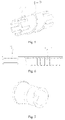
FIG. 1 is a schematic view of the steel wire bundle according various embodiments;
FIG. 2 is a sectional view of the steel wire bundle according to the present invention;
FIG. 3 is a sectional view of the central pipe according to the present invention;
FIG. 4 is a schematic view of the slurry output bracket according to the present invention;
FIG. 5 is a schematic view of the large stirring jacket according to the present invention;
FIG. 6 is a schematic view of the threaded casing according to the present invention; and
FIG. 7 is a schematic view of the slurry stop plug according to the present invention.
In the figures: 1—multiple parallel steel wires; 2—central pipe; 2-1—steel pipe; 2-2—plastic hose; 2-3—barb; 3—slurry output bracket; 3-1—pressure bearing body; 3-2—limit groove; 3-3—slurry outlet; 3-4—interface; 4—large stirring jacket; 4-1—welding groove I; 4-2—thread; 5—threaded casing; 5-1—welding groove II; 5-2—thread; 6—slurry stop plug; and 7—clamp.
DETAILED DESCRIPTION Technical Problem
in view of the above-mentioned drawbacks in the prior art, the various embodiments described herein provide a single-anchor centrally grouted full-length anchored steel wire bundle and a supporting method thereof, wherein, the requirement for length is met, the rod body is under uniform stress, the installation is easy and the cost is low.
Technical Scheme
to attain the above technical objects, a single-anchor centrally grouted full-length anchored steel wire bundle provided in the various embodiments described herein provide a main body of steel wire bundle and a tray and a nut arranged on a tail end of the main body of steel wire bundle, the main body of steel wire bundle comprises a central pipe and multiple strands of parallel steel wires which are arranged in parallel around the central pipe and in the same length as the central pipe, the central pipe is provided with a slurry output bracket which divides the main body of steel wire bundle into a front part and a rear part, the front part of the main body of steel wire bundle is provided with a plurality of large stirring jackets, the rear part of the main body of steel wire bundle is provided with a plurality of clamps at intervals, a threaded casing is provided on the tail end of the rear part of the main body of steel wire bundle, a slurry stop plug is provided on the main body of steel wire bundle at the front end of the threaded casing, the threaded casing is divided into a front part and a rear part, the front part of the threaded casing is provided with a plurality of welding grooves II, the rear part of the threaded casing is provided with threads on the outside, and the tray and the nut are arranged on the threads.
The central pipe is hollow and comprises a steel pipe and a plastic hose, the plastic hose is arranged at the front end, the steel pipe is arranged at the rear end, the threaded casing and the slurry stop plug are arranged outside the main body of steel wire bundle at the steel pipe, the central pipe in the remaining part of the main body of steel wire bundle is the plastic hose, barbs are arranged in the interior of a port of the plastic hose, the plastic hose is connected with the steel pipe via the barbs, the central pipe has a wall thickness of 1.5 mm˜2.5 mm and a length of 3,000 mm˜4,000 mm, the steel pipe has a length of 400 mm˜600 mm, the plastic hose has a length of 2,500 mm˜3,500 mm, and the steel pipe is connected with the plastic hose via the barbs so that the central pipe is sealed at the joint.
The slurry output bracket comprises a hollow spindle-shaped pressure bearing body, U-shaped limit grooves matching the number and diameter of the parallel steel wires and a plurality of slurry outlets connected with the interior of the central pipe are arranged on the thickest part of a middle section of the pressure bearing body, the tail end of the pressure bearing body is provided with an interface for connection with the central pipe, the parallel steel wires fix the slurry output bracket by means of the limit grooves, the surfaces of the spindle-shaped pressure bearing body are fitted to the parallel steel wires, the bottom of the limit groove has a diameter of 5 mm˜9 mm at the position where the steel wire is fixed, the slurry outlets and the limit grooves are arranged in misalignment, the slurry outlets has a diameter of 3 mm˜6 mm for discharge of the slurry, and the plurality of slurry outlets decrease the probability of grouting failure resulted from clogging of the slurry outlets.
The large stirring jacket is a hollow tubular structure and have a plurality of welding grooves I on both ends respectively, the welding grooves on the front end and the rear end of the large stirring jacket are located at the grooves between two parallel steel wires, stirring threads with the height of 5 mm and the thickness of 1 mm are arranged on the middle part of the large stirring jacket to facilitate stirring of an anchoring agent.
There are 6 strands of parallel steel wires, which are made of cold-drawn low-carbon steel wires with the diameter of 4 mm˜8 mm and the length of 3,000 mm˜4,000 mm. The welding groove of the threaded casing is located at the groove between two parallel steel wires, and has threads on the tail part, and the inner diameter of the threaded casing is 12-24 mm. The slurry stop plug is a rubber product in a horn shape, the inner diameter of a narrower opening of which is 12-24 mm, the inner diameter of a wider opening of which is 15-30 mm and the wall thickness of which is 2 mm, for sealing the slurry and preventing the slurry from flowing out of the hole. The clamps have a width of 8 mm and a thickness of 1 mm for fastening the steel wire bundle, and the number of the clamps is determined according to the length of the steel wire bundle.
A single-anchor centrally grouting full-length anchoring supporting method using a single-anchor centrally grouted full-length anchored steel wire bundle, comprising the following steps:
a. after cutting the coal with a tunneling machine, drilling an anchor rod borehole in the roadway roof with a jumbolter, wherein the length of the borehole is 100 mm˜150 mm smaller than the length of anchor rod;
b. putting a resin cartridge into the borehole and then the steel wire bundle, screwing the steel wire bundle into the borehole with the jumbolter, and utilizing the large stirring jacket at the front end of the steel wire bundle to stir the resin cartridge thoroughly to enhance the cohesion force between the resin cartridge and the roof strata;
c. mounting a slurry stop plug, a tray and a nut on the tail end of the steel wire bundle sequentially, then applying pre-tightening force to the steel wire bundle; thus, the anchoring work of the ends of the steel wire bundle is finished;
d. subsequently, performing central grouting for the steel wire bundle with a mobile pump truck without affecting quick tunneling of the working face; connecting a plurality of grouting pipes on the mobile pump truck to the central pipe in the steel wire bundle and starting grouting, so that the slurry flows through the central pipe via the grouting pipes and flows out of the slurry outlets of the slurry output bracket, after the entire borehole is fully filled with the slurry, loading the grouting pressure to 2 MPa and maintaining the grouting pressure for 5 min, then stopping the grouting and waiting for curing; thus, the steel wire bundle is anchored in full length so that the multiple strands of parallel steel wires form an organic whole and bear the stress uniformly when the rock mass deforms, and thereby the problem of large deformation and instability of the roadway is solved.
Benefits: with the above-mentioned technical solution, the various embodiments described herein have one or more of the following advantages over the prior art:
1) The steel wire bundle comprises 6 parallel steel wires, which bear the stress uniformly under working load, thereby avoiding stress concentration in the rod body of the steel wire bundle, reducing potential safety hazard and improving the safety factor of roadway supporting;
2) The steel wire bundle is made of flexible material, and the length of the steel wire bundle may be selected according to the geologic condition and the mining environment of the mine, and is not limited by the dimensions of the cross section of the roadway;
3) A plurality of large stirring jackets are provided at the front end of the steel wire bundle to stir the resin cartridge thoroughly, thereby enhancing the anchoring effect and avoiding anchoring failures.
4) The tail end of the steel wire bundle is provided with a threaded casing, and pre-tightening force can be applied via the threaded casing in the mounting process of the steel wire bundle; thus, the mounting is more convenient, and the working efficiency is improved;
5) The roof is supported solely by means of steel wire bundles; thus, the drawbacks of alternative construction with anchor rods and anchor ropes are avoided, the construction procedures are simplified, the roadway tunneling speed is increased, and safe and efficient production in the mine can be realized;
6) In the construction process, the ends of the steel wire bundle are anchored first, then central grouting is carried out for the steel wire bundle with a mobile pump truck to realize full-length anchoring without affecting the quick tunneling of the working face, thereby a thick anchoring rock beam for the roof can be formed, the problem of large deformation of a deep roadway can be solved, and the stability of the surrounding rock of the roadway is ensured; besides, since the later-stage central grouting for the steel wire bundle does not affect the normal construction at the working face, the tunneling speed is further improved, and mining imbalance in the mine is relieved greatly.
Hereunder example embodiments will be further described with reference to the drawings.
As shown in FIGS. 1 and 2, a single-anchor centrally grouted full-length anchored steel wire bundle provided in the present embodiment comprises a main body of steel wire bundle and a tray and a nut arranged on a tail end of the main body of steel wire bundle, the main body of steel wire bundle comprises a central pipe 2, the central pipe 2 is hollow and comprises a steel pipe 2-1 and a plastic hose 2-2, the plastic hose 2-2 is arranged at the front end, the steel pipe 2-1 is arranged at the rear end, the threaded casing 5 and the slurry stop plug are arranged outside the main body of steel wire bundle at the steel pipe 2-1, the central pipe 2 in the remaining part of the main body of steel wire bundle is the plastic hose 2-2, as shown in FIG. 3, barbs 2-3 are arranged in the interior of a port of the plastic hose 2-2, the plastic hose 2-2 is connected with the steel pipe 2-1 via the barbs 2-3, the central pipe 2 has a wall thickness of 1.5 mm˜2.5 mm and a length of 3,000 mm˜4,000 mm, the steel pipe 2-1 has a length of 400 mm˜600 mm, the plastic hose 2-2 has a length of 2,500 mm˜3,500 mm, and the steel pipe 2-1 is connected with the plastic hose 2-2 via the barbs so that the central pipe is sealed at the joint; multiple strands of parallel steel wires 1 are arranged in parallel around the central pipe 2, there are 6 strands of parallel steel wires 1, which are made of cold-drawn low-carbon steel wires with the diameter of 4 mm˜8 mm and the length of 3,000 mm˜4,000 mm, the parallel steel wires 1 are of the same length as the central pipe 2, the central pipe 2 is provided with a slurry output bracket 3 which divides the main body of steel wire bundle into a front part and a rear part as shown in FIG. 4, the slurry output bracket 3 comprises a hollow spindle-shaped pressure bearing body 3-1, U-shaped limit grooves 3-2 matching the number and diameter of the parallel steel wires 1 and a plurality of slurry outlets 3-3 connected with the interior of the central pipe 2 are arranged on the thickest part of a middle section of the pressure bearing body 3-1, the tail end of the pressure bearing body 3-1 is provided with an interface 3-4 for connection with the central pipe 2, the parallel steel wires 1 fix the slurry output bracket 3 by means of the limit grooves 3-2, the surfaces of the spindle-shaped pressure bearing body 3-1 are fitted to the parallel steel wires 1, the bottom of the limit groove 3-2 has a diameter of 5 mm˜9 mm at the position where the steel wire is fixed, the slurry outlets 3-3 and the limit grooves 3-2 are arranged in misalignment, the slurry outlets 3-3 has a diameter of 3 mm˜6 mm for discharge of the slurry, and the plurality of slurry outlets 3-3 decrease the probability of grouting failure resulted from clogging of the slurry outlets;
As shown in FIG. 5, the front part of the main body of steel wire bundle is provided with a plurality of large stirring jackets 4, the large stirring jacket 4 is a hollow tubular structure and have a plurality of welding grooves I 4-1 on both ends respectively, the welding grooves on the front end and the rear end of the large stirring jacket 4 are located at the grooves between two parallel steel wires, stirring threads 4-2 with the height of 5 mm and the thickness of 1 mm are arranged on the middle part of the large stirring jacket to facilitate stirring of an anchoring agent, the rear part of the main body of steel wire bundle is provided with a plurality of clamps 7 at intervals, the clamps 7 have a width of 8 mm and a thickness of 1 mm for fastening the steel wire bundle, and the number of the clamps 7 is determined according to the length of the steel wire bundle;
As shown in FIG. 6, a threaded casing 5 is provided on the tail end of the rear part of the main body of steel wire bundle, a slurry stop plug is provided on the main body of steel wire bundle at the front end of the threaded casing 5, the threaded casing 5 is divided into a front part and a rear part, the front part of the threaded casing 5 is provided with a plurality of welding grooves II 5-1, the rear part of the threaded casing 5 is provided with threads 5-2 on the outside, and the tray and the nut are arranged on the threads 5-2, the welding groove 5-1 of the threaded casing 5 is located at the groove between two parallel steel wires 1, and has threads 5-2 on the tail part, and the inner diameter of the threaded casing 5 is 12-24 mm, as shown in FIG. 7, the slurry stop plug 6 is a rubber product in a horn shape, the inner diameter of a narrower opening of which is 12-24 mm, the inner diameter of a wider opening of which is 15-30 mm and the wall thickness of which is 2 mm, for sealing the slurry and preventing the slurry from flowing out of the hole.
A single-anchor centrally grouting full-length anchoring supporting method using the single-anchor centrally grouted full-length anchored steel wire bundle, wherein, it comprises the following steps:
a. after cutting the coal with a tunneling machine, drilling an anchor rod borehole in the roadway roof with a jumbolter, wherein the length of the borehole is 100 mm˜150 mm smaller than the length of anchor rod;
b. putting a resin cartridge into the borehole and then the steel wire bundle, screwing the steel wire bundle into the borehole with the jumbolter, and utilizing the large stirring jacket 4 at the front end of the steel wire bundle to stir the resin cartridge thoroughly to enhance the cohesion force between the resin cartridge and the roof strata;
c. mounting a slurry stop plug 6, a tray and a nut on the tail end of the steel wire bundle sequentially, then applying pre-tightening force to the steel wire bundle; thus, the anchoring work of the ends of the steel wire bundle is finished;
d. subsequently, performing central grouting for the steel wire bundle with a mobile pump truck without affecting quick tunneling of the working face; connecting a plurality of grouting pipes on the mobile pump truck to the central pipe 2 in the steel wire bundle and starting grouting, so that the slurry flows through the central pipe 2 via the grouting pipes and flows out of the slurry outlets of the slurry output bracket 4, after the entire borehole is fully filled with the slurry, loading the grouting pressure to 2 MPa and maintaining the grouting pressure for 5 min, then stopping the grouting and waiting for curing; thus, the steel wire bundle is anchored in full length so that the multiple strands of parallel steel wires form an organic whole and bear the stress uniformly when the rock mass deforms, and thereby the problem of large deformation and instability of the roadway is solved.
A single-anchor centrally grouted full-length anchored steel wire bundle and a supporting method thereof, which are suitable for use in supporting engineering for the deep dynamic pressure roadway or soft rock roadway. The steel wire bundle consists of parallel steel wires and a central pipe, wherein multiple strands of parallel steel wires are arranged around the central pipe, the central pipe is provided with a slurry output bracket which divides the parallel steel wires into a front part and a rear part, the front part is provided with large stirring jackets, and the rear part is provided with a threaded casing on its tail end. After the coal is cut by a tunneling machine and a roadway is formed, the steel wire bundle is anchored at the ends, and the roadway tunneling speed is increased on a premise of ensuring roadway safety; central grouting is carried out for the steel wire bundle with a pump truck without affecting the quick roadway tunneling, so as to anchor the steel wire bundle in full length and ensure long-time stability of the roadway. The length of the steel wire bundle may be selected according to the geological conditions and the mining environment of the mine, and is not limited by the height of the roadway; the single-anchor centrally grouted supporting method realizes full-length anchoring of the steel wire bundle, and it not only improves the roadway tunneling speed and relieves mining imbalance in the mine, but also solves the problem of large deformation of the roadway.

Claims (9)

The invention claimed is:
1. A single-anchor centrally grouted full-length anchored steel wire bundle, comprising a main body of steel wire bundle and a tray and a nut arranged on a tail end of the main body of steel wire bundle, wherein, the main body of steel wire bundle comprises a central pipe and multiple strands of parallel steel wires which are arranged in parallel around the central pipe and in the same length as the central pipe, the central pipe is provided with a slurry output bracket which divides the main body of steel wire bundle into a front part and a rear part, the front part of the main body of steel wire bundle is provided with a large stirring jacket, the rear part of the main body of steel wire bundle is provided with a plurality of clamps at intervals, a threaded casing is provided on the tail end of the rear part of the main body of steel wire bundle, a slurry stop plug is provided on the main body of steel wire bundle at the front end of the threaded casing, the threaded casing is divided into a front part and a rear part, the front part of the threaded casing is provided with a plurality of first welding grooves, the rear part of the threaded casing is provided with threads on the outside, and the tray and the nut are arranged on the threads.
2. The single-anchor centrally grouted full-length anchored steel wire bundle according to claim 1, wherein, the central pipe is hollow and comprises a steel pipe and a plastic hose, the plastic hose is arranged at the front end, the steel pipe is arranged at the rear end, the threaded casing and the slurry stop plug are arranged outside the main body of steel wire bundle at the steel pipe, the central pipe in the remaining part of the main body of steel wire bundle is the plastic hose, barbs are arranged in the interior of a port of the plastic hose, the plastic hose is connected with the steel pipe-via the barbs, the central pipe has a wall thickness of 1.5 millimeter (mm)-2.5 mm and a length of 3,000 mm-4,000 mm, the steel pipe has a length of 400 mm-600 mm, the plastic hose has a length of 2,500 mm-3,500 mm, and the steel pipe is connected with the plastic hose-via the barbs so that the central pipe is sealed at the joint.
3. The single-anchor centrally grouted full-length anchored steel wire bundle according to claim 1, wherein, the slurry output bracket comprises a hollow spindle-shaped pressure bearing body, U-shaped limit grooves matching the number and diameter of the parallel steel wires and a plurality of slurry outlets connected with the interior of the central pipe are arranged on the thickest part of a middle section of the pressure bearing body, the tail end of the pressure bearing body is provided with an interface for connection with the central pipe, the parallel steel wires fix the slurry output bracket by means of the limit grooves, the surfaces of the spindle-shaped pressure bearing body are fitted to the parallel steel wires, the bottom of the limit groove has a diameter of 5 millimeter (mm)-9 mm at the position where the steel wire is fixed, the slurry outlets and the limit grooves are arranged in misalignment, the slurry outlets has a diameter of 3 mm-6 mm for discharge of the slurry, and the plurality of slurry outlets decrease the probability of grouting failure resulted from clogging of the slurry outlets.
4. The single-anchor centrally grouted full-length anchored steel wire bundle according to claim 1, wherein, the large stirring jacket is a hollow tubular structure and have a plurality of second welding grooves on both ends respectively, the second welding grooves on the front end and the rear end of the large stirring jacket are located at the grooves between two parallel steel wires, stirring threads with the height of 5 millimeter (mm) and the thickness of 1 mm are arranged on the middle part of the large stirring jacket to facilitate stirring of an anchoring agent.
5. The single-anchor centrally grouted full-length anchored steel wire bundle according to claim 1, wherein, there are 6 strands of parallel steel wires, which are made of cold-drawn low-carbon steel wires with the diameter of 4 millimeter (mm)-8 mm and the length of 3,000 mm-4,000 mm.
6. The single-anchor centrally grouted full-length anchored steel wire bundle according to claim 1, wherein, the first welding groove of the threaded casing is located at the groove between two parallel steel wires, and the tail end of the threaded casing is provided with threads, and the inner diameter of the threaded casing is 12-24 millimeter (mm).
7. The single-anchor centrally grouted full-length anchored steel wire bundle according to claim 1, wherein, the slurry stop plug is a rubber product in a horn shape, the inner diameter of a narrower opening of which is 12-24 millimeter (mm), the inner diameter of a wider opening of which is 15-30 mm and the wall thickness of which is 2 mm, for sealing the slurry and preventing the slurry from flowing out of a hole.
8. The single-anchor centrally grouted full-length anchored steel wire bundle according to claim 1, wherein, the clamps have a width of 8 millimeter (mm) and a thickness of 1 mm for fastening the steel wire bundle, and the number of the clamps is determined according to the length of the steel wire bundle.
9. A supporting method using the single-anchor centrally grouted full-length anchored steel wire bundle according to claim 1, wherein, it comprises the following steps:
after cutting coal with a tunneling machine, drilling a borehole in the roadway roof with an anchor rod of a jumbolter, wherein the length of the borehole is 100 millimeter (mm) 150 mm smaller than the length of the anchor rod;
putting a resin cartridge into the borehole and then the steel wire bundle, screwing the steel wire bundle into the borehole with the jumbolter, and utilizing the large stirring jacket at the front end of the steel wire bundle to stir the resin cartridge thoroughly to enhance the cohesion force between the resin cartridge and the roof strata;
mounting the slurry stop plug, the tray and the nut on the tail end of the steel wire bundle sequentially, then applying pre-tightening force to the steel wire bundle; thus, the anchoring work of the ends of the steel wire bundle is finished; and
subsequently, performing central grouting for the steel wire bundle with a mobile pump truck without affecting quick tunneling of the working face; connecting a plurality of grouting pipes on the mobile pump truck to the central pipe in the steel wire bundle and starting grouting, so that the slurry flows through the central pipe via the grouting pipes and flows out of a plurality of slurry outlets of the slurry output bracket after the entire borehole is fully filled with the slurry, loading the grouting pressure to 2 Megapascals (MPa) and maintaining the grouting pressure for 5 minutes, then stopping the grouting and waiting for curing; thus, the steel wire bundle is anchored in full length so that the multiple strands of parallel steel wires form an organic whole and bear the stress uniformly when the rock mass deforms, and thereby the problem of large deformation and instability of the roadway is solved.
US16/624,541 2018-08-20 2018-10-29 Single-anchor centrally grouted full-length anchored steel wire bundle and supporting method thereof Active 2039-05-18 US11280195B2 (en)

Applications Claiming Priority (3)

Application Number Priority Date Filing Date Title
CN201810947765.4 2018-08-20
CN201810947765.4A CN109098742B (en) 2018-08-20 2018-08-20 A single-anchor-injection-type full-length anchoring steel wire bundle and its supporting method
PCT/CN2018/112375 WO2020037815A1 (en) 2018-08-20 2018-10-29 Single anchor concentrated grouting full-length anchored steel wire tendon and method for supporting same

Publications (2)

Publication Number Publication Date
US20210340872A1 US20210340872A1 (en) 2021-11-04
US11280195B2 true US11280195B2 (en) 2022-03-22

Family

ID=64850460

Family Applications (1)

Application Number Title Priority Date Filing Date
US16/624,541 Active 2039-05-18 US11280195B2 (en) 2018-08-20 2018-10-29 Single-anchor centrally grouted full-length anchored steel wire bundle and supporting method thereof

Country Status (5)

Country Link
US (1) US11280195B2 (en)
CN (1) CN109098742B (en)
AU (1) AU2018425105B2 (en)
CA (1) CA3063370C (en)
WO (1) WO2020037815A1 (en)

Families Citing this family (13)

* Cited by examiner, † Cited by third party
Publication number Priority date Publication date Assignee Title
CN109681249B (en) * 2019-01-25 2020-06-23 山东焱鑫矿用材料加工有限公司 Construction method of grouting anchor cable for medium-exhaust mine
CN111395775B (en) * 2020-04-07 2021-09-24 中铁十二局集团建筑安装工程有限公司 Construction method for plugging outer wall base mortar of sandwich insulation board of fabricated building
CN113062754B (en) * 2021-04-27 2023-07-25 常凤琴 Grouting end slurry stopping method for steel pipe grouting
CN113202531B (en) * 2021-06-24 2024-08-20 徐州矿务集团有限公司 Multi-layer layered fixed-length grouting device for roof of coal roadway under multiple disturbance and anchoring method
CN114087000B (en) * 2021-11-18 2023-08-04 甘肃公航旅永积高速公路项目管理有限公司 Recyclable positioning grouting anchor pipe and positioning grouting anchoring method
CN114352332B (en) * 2021-12-20 2025-03-04 淮北矿业股份有限公司 An automatic and precise pressure control device for grouting anchor rod
CN114483129A (en) * 2022-01-26 2022-05-13 嵩县山金矿业有限公司 Full-length anchoring method for prestressed long anchor cable of underground broken surrounding rock large-span chamber
CN115234254B (en) * 2022-08-04 2025-03-04 山西潞安环保能源开发股份有限公司常村煤矿 A directional grouting device for mine tunnel reinforcement
CN115628092A (en) * 2022-10-26 2023-01-20 山东安科矿山支护技术有限公司 Anchor hole grouting device and anchor grouting method of anchor rod (cable)
CN116792132B (en) * 2023-07-10 2026-01-09 中国矿业大学 A recyclable spray-type segmented grouting pressure-relieving anchor bolt device and its application method
CN117266904B (en) * 2023-10-17 2025-08-29 中国矿业大学 A flexible hollow anchor rod and construction method integrating digital monitoring
CN117386423B (en) * 2023-11-08 2024-05-10 烟台佑利技术有限公司 Full-length cementation anchor cable with sizing hierarchical control structure and use method
CN120426083A (en) * 2025-05-06 2025-08-05 中国矿业大学 A full-length anchoring method for thixotropic anchoring agent

Citations (12)

* Cited by examiner, † Cited by third party
Publication number Priority date Publication date Assignee Title
DE3532070A1 (en) 1985-09-09 1987-03-26 Bwz Berg Ind Tech Roof bolt, in particular for mining
US4664555A (en) * 1985-03-05 1987-05-12 Dyckerhoff & Widmann Aktiengesellschaft Tension member for a rock anchor or the like
US6189281B1 (en) * 1997-08-16 2001-02-20 International Intec Patent Holding Establishment Injection anchor
US6428243B1 (en) * 1996-09-09 2002-08-06 Quantax Pty Ltd Cable bolt
US20040136788A1 (en) * 2001-06-04 2004-07-15 Hindle David John Rock bolt and method of use
CN201507317U (en) 2009-09-15 2010-06-16 济南澳科矿山工程技术有限公司 Anchoring-grouting anchor rope
CN102828760A (en) 2012-09-05 2012-12-19 淮南市顺辉锚固有限公司 Pre-stress spiral rib hollow grouting anchor rope
CN102852144A (en) 2012-09-25 2013-01-02 天津银龙预应力材料股份有限公司 Novel anchor rod
CN103898904A (en) 2014-03-06 2014-07-02 天津银龙预应力材料股份有限公司 Hollow anchor rod
CN105221171A (en) 2015-10-23 2016-01-06 于守东 A kind of anti-skidding self-styled cellular type grouting cable anchor
CN205206857U (en) 2015-12-21 2016-05-04 新泰惠众经贸有限公司 Practical cavity slip casting anchor rope
CN207261029U (en) 2017-09-28 2018-04-20 李华诚 Novel hollow grouting cable anchor

Family Cites Families (6)

* Cited by examiner, † Cited by third party
Publication number Priority date Publication date Assignee Title
CN2572005Y (en) * 2002-09-13 2003-09-10 王永伯 Support frame for anchor end of anchorage cable
CN2771484Y (en) * 2005-07-19 2006-04-12 山东清大实业集团有限公司 Underground engineering slip casting anchorage cable
CN102535458A (en) * 2010-12-31 2012-07-04 中航勘察设计研究院有限公司 Reinforced cement-soil anchor bolt and construction method thereof
CN103382847B (en) * 2013-07-26 2015-08-19 中国矿业大学 Prestressed drilling, anchoring and grouting anchor cable and supporting method
CN103615272A (en) * 2013-11-07 2014-03-05 山东交通学院 Hollow anchor rod with rebar framework and construction method of hollow anchor rod
CN104405424A (en) * 2014-11-17 2015-03-11 神华集团有限责任公司 Full-length-anchoring anchor rod and anchoring method

Patent Citations (12)

* Cited by examiner, † Cited by third party
Publication number Priority date Publication date Assignee Title
US4664555A (en) * 1985-03-05 1987-05-12 Dyckerhoff & Widmann Aktiengesellschaft Tension member for a rock anchor or the like
DE3532070A1 (en) 1985-09-09 1987-03-26 Bwz Berg Ind Tech Roof bolt, in particular for mining
US6428243B1 (en) * 1996-09-09 2002-08-06 Quantax Pty Ltd Cable bolt
US6189281B1 (en) * 1997-08-16 2001-02-20 International Intec Patent Holding Establishment Injection anchor
US20040136788A1 (en) * 2001-06-04 2004-07-15 Hindle David John Rock bolt and method of use
CN201507317U (en) 2009-09-15 2010-06-16 济南澳科矿山工程技术有限公司 Anchoring-grouting anchor rope
CN102828760A (en) 2012-09-05 2012-12-19 淮南市顺辉锚固有限公司 Pre-stress spiral rib hollow grouting anchor rope
CN102852144A (en) 2012-09-25 2013-01-02 天津银龙预应力材料股份有限公司 Novel anchor rod
CN103898904A (en) 2014-03-06 2014-07-02 天津银龙预应力材料股份有限公司 Hollow anchor rod
CN105221171A (en) 2015-10-23 2016-01-06 于守东 A kind of anti-skidding self-styled cellular type grouting cable anchor
CN205206857U (en) 2015-12-21 2016-05-04 新泰惠众经贸有限公司 Practical cavity slip casting anchor rope
CN207261029U (en) 2017-09-28 2018-04-20 李华诚 Novel hollow grouting cable anchor

Non-Patent Citations (2)

* Cited by examiner, † Cited by third party
Title
English translation of International Search Report for International Application No. PCT/CN2018/112375, dated Feb. 27, 2019.
International Search Report and Written Opinion for PCT/CN2018/112375 in Chinese, nine (9) pages, English translation not available.

Also Published As

Publication number Publication date
CN109098742A (en) 2018-12-28
AU2018425105B2 (en) 2021-02-18
AU2018425105A1 (en) 2020-03-05
CA3063370C (en) 2022-11-15
CN109098742B (en) 2019-11-08
WO2020037815A1 (en) 2020-02-27
CA3063370A1 (en) 2020-02-20
US20210340872A1 (en) 2021-11-04

Similar Documents

Publication Publication Date Title
US11280195B2 (en) Single-anchor centrally grouted full-length anchored steel wire bundle and supporting method thereof
CN110939456B (en) High-stress roadway combined ring body beam supporting structure and construction method thereof
CA3156369C (en) Flexible anchor rod
AU2011289463B2 (en) Fully grouted cable bolt
CN201236718Y (en) Inner slip-casting anchor cable
CN109083668A (en) A kind of grouting and reinforcing anchor pole suitable for high stress breaking surrounding rock supporting
CN109681249B (en) Construction method of grouting anchor cable for medium-exhaust mine
CN104405423A (en) Mining grouting anchor rope
CN102704971A (en) Grouting and Grouting-stopping anchor cable inside hole
CN115182765A (en) Slip casting NPR anchor cable
CN116677436A (en) A multi-hole yielding pressure bolt device capable of segmental grouting and its application method
CN206916739U (en) A kind of mountain area side slope prestress anchorage cable
CN102748048A (en) Hole wall grouting anchor cable
CN109854287A (en) A kind of Novel hollow grouting cable anchor and preparation method thereof
CN205858371U (en) A kind of colliery big cross section digging laneway combined support structure
CN114215531A (en) Coal mine tunnel ultra-soft surrounding rock modification method and structure
CN204327134U (en) A kind of prestressing force balance anchor cable
CN104612150B (en) A kind of anchor cable and its Inner bolt head administered for rock side slope
CN210194627U (en) Hole wall guniting device
CN218093096U (en) Anchor hole grouting device, anchor grouting anchor rod and anchor grouting anchor cable
CN107060855A (en) A kind of new type mining anchor cable
CN118088240A (en) Expansion shell type controllable deformation anchor rod
CN109098744A (en) A kind of anchor pole squash type Anchor Agent connecting pipe and application method
CN212406765U (en) Main body supporting structure applied to roadway surrounding rock supporting
CN212272259U (en) Whole set grouting anchor cable

Legal Events

Date Code Title Description
AS Assignment

Owner name: CHINA UNIVERSITY OF MINING AND TECHNOLOGY, CHINA

Free format text: PATENT ASSIGNMENT;ASSIGNORS:ZHANG, NONG;XIE, ZHENGZHENG;ZHOU, JUNYAO;AND OTHERS;REEL/FRAME:051378/0302

Effective date: 20191120

FEPP Fee payment procedure

Free format text: ENTITY STATUS SET TO UNDISCOUNTED (ORIGINAL EVENT CODE: BIG.); ENTITY STATUS OF PATENT OWNER: SMALL ENTITY

FEPP Fee payment procedure

Free format text: ENTITY STATUS SET TO SMALL (ORIGINAL EVENT CODE: SMAL); ENTITY STATUS OF PATENT OWNER: SMALL ENTITY

STPP Information on status: patent application and granting procedure in general

Free format text: NON FINAL ACTION MAILED

STPP Information on status: patent application and granting procedure in general

Free format text: RESPONSE TO NON-FINAL OFFICE ACTION ENTERED AND FORWARDED TO EXAMINER

STPP Information on status: patent application and granting procedure in general

Free format text: NOTICE OF ALLOWANCE MAILED -- APPLICATION RECEIVED IN OFFICE OF PUBLICATIONS

STCF Information on status: patent grant

Free format text: PATENTED CASE

MAFP Maintenance fee payment

Free format text: PAYMENT OF MAINTENANCE FEE, 4TH YR, SMALL ENTITY (ORIGINAL EVENT CODE: M2551); ENTITY STATUS OF PATENT OWNER: SMALL ENTITY

Year of fee payment: 4