US11276594B2 - Systems, apparatus, and methods for an improved load port backplane - Google Patents
Systems, apparatus, and methods for an improved load port backplane Download PDFInfo
- Publication number
- US11276594B2 US11276594B2 US16/742,567 US202016742567A US11276594B2 US 11276594 B2 US11276594 B2 US 11276594B2 US 202016742567 A US202016742567 A US 202016742567A US 11276594 B2 US11276594 B2 US 11276594B2
- Authority
- US
- United States
- Prior art keywords
- block
- leveling
- hole
- backplane
- slotted
- Prior art date
- Legal status (The legal status is an assumption and is not a legal conclusion. Google has not performed a legal analysis and makes no representation as to the accuracy of the status listed.)
- Active, expires
Links
Images


Classifications
-
- H—ELECTRICITY
- H01—ELECTRIC ELEMENTS
- H01L—SEMICONDUCTOR DEVICES NOT COVERED BY CLASS H10
- H01L21/00—Processes or apparatus adapted for the manufacture or treatment of semiconductor or solid state devices or of parts thereof
- H01L21/67—Apparatus specially adapted for handling semiconductor or electric solid state devices during manufacture or treatment thereof; Apparatus specially adapted for handling wafers during manufacture or treatment of semiconductor or electric solid state devices or components ; Apparatus not specifically provided for elsewhere
- H01L21/673—Apparatus specially adapted for handling semiconductor or electric solid state devices during manufacture or treatment thereof; Apparatus specially adapted for handling wafers during manufacture or treatment of semiconductor or electric solid state devices or components ; Apparatus not specifically provided for elsewhere using specially adapted carriers or holders; Fixing the workpieces on such carriers or holders
- H01L21/6735—Closed carriers
- H01L21/67383—Closed carriers characterised by substrate supports
-
- H—ELECTRICITY
- H01—ELECTRIC ELEMENTS
- H01L—SEMICONDUCTOR DEVICES NOT COVERED BY CLASS H10
- H01L21/00—Processes or apparatus adapted for the manufacture or treatment of semiconductor or solid state devices or of parts thereof
- H01L21/67—Apparatus specially adapted for handling semiconductor or electric solid state devices during manufacture or treatment thereof; Apparatus specially adapted for handling wafers during manufacture or treatment of semiconductor or electric solid state devices or components ; Apparatus not specifically provided for elsewhere
- H01L21/677—Apparatus specially adapted for handling semiconductor or electric solid state devices during manufacture or treatment thereof; Apparatus specially adapted for handling wafers during manufacture or treatment of semiconductor or electric solid state devices or components ; Apparatus not specifically provided for elsewhere for conveying, e.g. between different workstations
- H01L21/67763—Apparatus specially adapted for handling semiconductor or electric solid state devices during manufacture or treatment thereof; Apparatus specially adapted for handling wafers during manufacture or treatment of semiconductor or electric solid state devices or components ; Apparatus not specifically provided for elsewhere for conveying, e.g. between different workstations the wafers being stored in a carrier, involving loading and unloading
- H01L21/67772—Apparatus specially adapted for handling semiconductor or electric solid state devices during manufacture or treatment thereof; Apparatus specially adapted for handling wafers during manufacture or treatment of semiconductor or electric solid state devices or components ; Apparatus not specifically provided for elsewhere for conveying, e.g. between different workstations the wafers being stored in a carrier, involving loading and unloading involving removal of lid, door, cover
-
- H—ELECTRICITY
- H01—ELECTRIC ELEMENTS
- H01L—SEMICONDUCTOR DEVICES NOT COVERED BY CLASS H10
- H01L21/00—Processes or apparatus adapted for the manufacture or treatment of semiconductor or solid state devices or of parts thereof
- H01L21/67—Apparatus specially adapted for handling semiconductor or electric solid state devices during manufacture or treatment thereof; Apparatus specially adapted for handling wafers during manufacture or treatment of semiconductor or electric solid state devices or components ; Apparatus not specifically provided for elsewhere
- H01L21/677—Apparatus specially adapted for handling semiconductor or electric solid state devices during manufacture or treatment thereof; Apparatus specially adapted for handling wafers during manufacture or treatment of semiconductor or electric solid state devices or components ; Apparatus not specifically provided for elsewhere for conveying, e.g. between different workstations
- H01L21/67763—Apparatus specially adapted for handling semiconductor or electric solid state devices during manufacture or treatment thereof; Apparatus specially adapted for handling wafers during manufacture or treatment of semiconductor or electric solid state devices or components ; Apparatus not specifically provided for elsewhere for conveying, e.g. between different workstations the wafers being stored in a carrier, involving loading and unloading
- H01L21/67775—Docking arrangements
-
- H—ELECTRICITY
- H01—ELECTRIC ELEMENTS
- H01L—SEMICONDUCTOR DEVICES NOT COVERED BY CLASS H10
- H01L21/00—Processes or apparatus adapted for the manufacture or treatment of semiconductor or solid state devices or of parts thereof
- H01L21/67—Apparatus specially adapted for handling semiconductor or electric solid state devices during manufacture or treatment thereof; Apparatus specially adapted for handling wafers during manufacture or treatment of semiconductor or electric solid state devices or components ; Apparatus not specifically provided for elsewhere
- H01L21/677—Apparatus specially adapted for handling semiconductor or electric solid state devices during manufacture or treatment thereof; Apparatus specially adapted for handling wafers during manufacture or treatment of semiconductor or electric solid state devices or components ; Apparatus not specifically provided for elsewhere for conveying, e.g. between different workstations
- H01L21/67763—Apparatus specially adapted for handling semiconductor or electric solid state devices during manufacture or treatment thereof; Apparatus specially adapted for handling wafers during manufacture or treatment of semiconductor or electric solid state devices or components ; Apparatus not specifically provided for elsewhere for conveying, e.g. between different workstations the wafers being stored in a carrier, involving loading and unloading
- H01L21/67778—Apparatus specially adapted for handling semiconductor or electric solid state devices during manufacture or treatment thereof; Apparatus specially adapted for handling wafers during manufacture or treatment of semiconductor or electric solid state devices or components ; Apparatus not specifically provided for elsewhere for conveying, e.g. between different workstations the wafers being stored in a carrier, involving loading and unloading involving loading and unloading of wafers
Definitions
- the present application relates to electronic device manufacturing systems, and more specifically to systems, apparatus, and methods for an improved load port backplane.
- Equipment front end modules sometimes referred to as factory interfaces (FIs) provide a non-reactive environment for transferring substrates from carriers to processing tools. This is achieved by sealing the interior volume of the EFEM as much as is practical and flooding the interior volume with a gas such as nitrogen that is generally non-reactive with substrate materials. The non-reactive gas forces out any reactive gases such as oxygen from the EFEM.
- a load port for docking a substrate carrier is typically attached to the front face of an EFEM.
- the load port includes a backplane that ideally is sealed against the face of the EFEM. However, it can be difficult to reliably seal a conventional backplane against the EFEM. Thus, what is needed are systems, apparatus, and methods for an improved load port backplane.
- a load port system in some embodiments, includes a backplane assembly supporting a docking tray and a substrate carrier opener, wherein the backplane assembly includes a backplane; a leveling block coupleable to an equipment front end module (EFEM); a conical hole adjustment assembly coupled between the leveling block and the backplane; and a slotted hole adjustment assembly coupled between the leveling block and the backplane.
- the conical hole adjustment assembly includes a conical hole block coupled to the leveling block at a first end; a threaded block coupled to the backplane; and an adjustment bolt coupled to the conical hole block and the threaded block.
- a backplane assembly includes a backplane; a leveling block coupleable to an equipment front end module (EFEM); a conical hole adjustment assembly coupled between the leveling block and the backplane; and a slotted hole adjustment assembly coupled between the leveling block and the backplane.
- the conical hole adjustment assembly includes a conical hole block coupled to the leveling block at a first end; a threaded block coupled to the backplane; and an adjustment bolt coupled to the conical hole block and the threaded block.
- a method of sealing a load port backplane to an Equipment Front End Module includes providing a load port including a backplane assembly having a leveling block coupled to a backplane of the load port with a conical hole adjustment assembly and a slotted adjustment assembly; coupling the leveling block to the EFEM; and rotating a leveling adjustment bolt in the conical hole adjustment assembly to adjust roll of the backplane.
- EFEM Equipment Front End Module
- FIG. 1 is a block diagram depicting an example of an electronic device processing system according to some embodiments.
- FIG. 2A is a front isometric view diagram depicting example load port according to some embodiments.
- FIG. 2B is a rear isometric view diagram depicting an example load port according to some embodiments.
- FIG. 3 is a rear plan view diagram depicting an example load port backplane assembly according to some embodiments.
- FIG. 4A is a cross-sectional view diagram depicting a first backplane adjustment mechanism according to some embodiments.
- FIG. 4B is a cross-sectional view diagram depicting a second backplane adjustment mechanism according to some embodiments.
- FIG. 5 is a flowchart illustrating an example method according to some embodiments.
- Embodiments described herein provide systems, apparatus, and methods for an improved load port backplane that allows a load port to be reliably sealed to an equipment front end module (EFEM) of an electronic device manufacturing system.
- An EFEM typically includes a transfer robot in an enclosed, positive pressure, non-reactive gas (e.g., nitrogen) environment and the EFEM is mounted to a substrate processing tool.
- the EFEM enables transfer of substrates (e.g., without exposure to reactive gases or other contamination) between a substrate carrier docked on a load port (e.g., in a cleanroom environment) and the substrate processing tool.
- a seal is maintained between the backplane of the load port and the EFEM.
- conventional backplanes do not include mounting hardware that easily enables adjustment of the backplane relative to the front face of the EFEM.
- novel embodiments described herein include the use of a leveling block with spherical washers and a conical hole mounting block that facilitate both pitch and roll adjustments to the orientation of the backplane so that the surface of the backplane can be aligned with and made coplanar with the front surface of the EFEM so a sealing member can be evenly compressed.
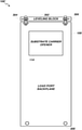
- FIG. 1 a block diagram of an example electronic device processing system 100 according to some embodiments is shown.
- the system 100 includes a substrate processing tool 102 coupled to an EFEM 104 .
- the EFEM 104 is coupled to a backplane 106 of a load port 108 .
- a docking tray 110 of the load port 108 is adapted to support a substrate carrier 112 which can be opened by a substrate carrier opener 114 of the load port 108 .
- the backplane 106 is mounted on the EFEM 104 with a compressible seal 116 that runs along the periphery of the major surface of the backplane 106 .
- FIGS. 2A and 2B depict front and rear isometric views of the load port 108 , respectively.
- the compressible seal 116 is shown on the rear surface of the backplane 106 .
- FIG. 3 a detailed front plan view of a backplane assembly 106 ′ is shown.
- the backplane assembly 106 ′ includes a leveling block 302 , conical hole adjustment hardware 304 , slotted adjustment hardware 306 , and lower attachment assembly 308 (e.g., bolts, screws, or other fasteners).
- the leveling block 302 attaches to the face of the EFEM 104 .
- the leveling block 302 can be bolted directly to the front facing surface of the EFEM 104 .
- FIGS. 3 a detailed front plan view of a backplane assembly 106 ′ is shown.
- the backplane assembly 106 ′ includes a leveling block 302 , conical hole adjustment hardware 304 , slotted adjustment hardware 306 , and lower attachment assembly 308 (e.g., bolts, screws, or other fasteners).
- the leveling block 302 attaches to the face of the EFEM 104 .
- the leveling block 302 can
- conical hole adjustment hardware 304 and slot adjustment hardware 306 both support the backplane 106 and allow the backplane 106 to be adjusted in terms of pitch (e.g., tilt backward into and forward out of the paper) and roll (e.g., clockwise and counter-clockwise rotation).
- FIG. 4A is a magnified cross-section view of the conical hole adjustment hardware 304 .
- a leveling adjustment bolt 402 A extends from the leveling block 302 to the backplane 106 .
- the leveling adjustment bolt 402 A is coupled to the leveling block 302 via a conical hole block 404 A which is coupled to the leveling block 302 via bolts 405 A.
- the leveling adjustment bolt 402 A is coupled to the backplane 106 via a threaded hole block 406 A which is coupled to the backplane 106 via bolts 407 A.
- the head 408 A of the leveling adjustment bolt 402 A rests on a first spherical washer pair 410 A which rests on the conical hole block 404 A.
- a second spherical washer pair 412 A is secured against the conical hole block 404 A by a first lock nut 414 A.
- a second lock nut 416 A is used to secure the leveling adjustment bolt 402 A in the threaded hole block 406 A.
- the conical hole block 404 A includes a hole that is expanded in the lower portion of the block to create an annular gap 418 A around the leveling adjustment bolt 402 A.
- This annular gap 418 A provides space for the leveling adjustment bolt 402 A to swivel when adjustments are made.
- the annular gap 418 A can be formed by making the through hole in the conical hole block 404 A have two different diameters (e.g., smaller in the upper portion and larger in the lower portion) or by forming the through hole with a conical or tapering shape. As shown in FIG. 4A , the top and bottom openings of the through hole in the conical hole block 404 A can be beveled to provide further clearance for swivel of the leveling adjustment bolt 402 A.
- the annular gap 418 A is large enough to accommodate approximately 0.25 degrees to approximately 2 degrees of swivel during adjustment.
- the through hole in the conical hole block 404 A is approximately 1.05 times to approximately 1.1 times the diameter of the leveling adjustment bolt 402 A. Further, by using the first and second spherical washer pairs 410 A, 412 A, binding of the leveling adjustment bolt 402 A (e.g., due to the weight of the supported backplane 106 ) is avoided and the leveling adjustment bolt 402 A is better able to swivel in the conical hole block 404 A.
- the leveling adjustment bolt 402 A In operation, before the lock nuts 414 A, 416 A are tightened, turning the leveling adjustment bolt 402 A clockwise, raises the left side of the backplane 106 (e.g., adjusts the roll of the backplane 106 in the clockwise direction) and turning the leveling adjustment bolt 402 A counter-clockwise, lowers the left side of the backplane 106 (e.g., adjusts the roll of the backplane 106 in the counter-clockwise direction) As the roll of the backplane 106 is adjusted, the leveling adjustment bolt 402 A swivels in the conical hole block 404 A.
- FIG. 4B is a magnified cross-section view of the slotted adjustment hardware 306 .
- a leveling adjustment bolt 402 B extends from the leveling block 302 to the backplane 106 .
- the leveling adjustment bolt 402 B is coupled to the leveling block 302 via a slotted block 404 B which is coupled to the leveling block 302 via bolts 405 B.
- the leveling adjustment bolt 402 B is coupled to the backplane 106 via a threaded hole block 406 B which is coupled to the backplane 106 via bolts 407 B.
- the head 408 B of the leveling adjustment bolt 402 B rests on a first spherical washer pair 410 B which rests on the slotted block 404 B.
- a second spherical washer pair 412 B is secured against the slotted block 404 B by a first lock nut 414 B.
- a second lock nut 416 B is used to secure the leveling adjustment bolt 402 B in the threaded hole block 406 B.
- the slotted block 404 B includes a slot 418 B that has a longitudinal dimension that extends in the same direction as the longitudinal dimension of the slotted block 404 B. This arrangement allows freedom of motion in the roll directions but restricts motion in the pitch directions. In other words, the leveling adjustment bolt 402 B is free to swivel clockwise and counter-clockwise but is restricted from tilting forward and back.
- the leveling adjustment bolt 402 B In operation, before the lock nuts 414 B, 416 B are tightened, turning the leveling adjustment bolt 402 B clockwise, raises the right side of the backplane 106 (e.g., adjusts the roll of the backplane 106 in the counter-clockwise direction) and turning the leveling adjustment bolt 402 B counter-clockwise, lowers the right side of the backplane 106 (e.g., adjusts the roll of the backplane 106 in the clockwise direction). As the roll of the backplane 106 is adjusted, the leveling adjustment bolt 402 B swivels in the slotted block 404 B.
- a conical hole block 404 A on one side of the leveling block 302 that restricts the leveling adjustment bolt 402 A to a fixed position but allows both pitch and roll swivel
- a slotted block 404 B on the other side that accommodates lateral adjustment and roll swivel
- Another benefit of the conical hole block 404 A and slotted block 404 B configuration is to ensure positional repeatability of the load port backplane 106 with respect to the EFEM 104 .
- the hole block 404 A arrangement can serve as the reference point about which all other load port position/orientation adjustments are made.
- FIG. 5 a flowchart depicting an example method 500 of sealing a load port backplane to an EFEM is depicted.
- a load port including a backplane assembly having a leveling block coupled to a backplane of the load port with conical hole adjustment hardware 304 on one of the leveling block and slotted adjustment hardware 306 on the other end is provided ( 502 ).
- the leveling block is coupled to the EFEM ( 504 ).
- a leveling adjustment bolt in the conical hole adjustment hardware is rotated to adjust the roll of the backplane to align a seal on the backplane relative to a desired position on the EFEM ( 506 ).
- a leveling adjustment bolt in the slotted adjustment hardware is rotated to further adjust the roll to align the seal on the backplane relative to the desired position on the EFEM ( 508 ).
- Adjustment bolts attaching the leveling block to the EFEM are adjusted to bring the backplane coplanar with the front surface of the EFEM ( 510 ).
Abstract
A method is for sealing a backplane component of a load port system to an equipment front end module (EFEM). The method includes mounting a leveling block to the EFEM. A conical hole adjustment assembly is coupled between a first distal end of the leveling block and the backplane component. The method further includes rotating a first leveling adjustment bolt in the conical hole adjustment assembly to align the backplane component with the EFEM.
Description
This application is a divisional application of U.S. patent application Ser. No. 15/348,964, filed on Nov. 10, 2016, the entire content of which is incorporated by reference herein.
The present application relates to electronic device manufacturing systems, and more specifically to systems, apparatus, and methods for an improved load port backplane.
Equipment front end modules (EFEMs), sometimes referred to as factory interfaces (FIs), provide a non-reactive environment for transferring substrates from carriers to processing tools. This is achieved by sealing the interior volume of the EFEM as much as is practical and flooding the interior volume with a gas such as nitrogen that is generally non-reactive with substrate materials. The non-reactive gas forces out any reactive gases such as oxygen from the EFEM. A load port for docking a substrate carrier is typically attached to the front face of an EFEM. The load port includes a backplane that ideally is sealed against the face of the EFEM. However, it can be difficult to reliably seal a conventional backplane against the EFEM. Thus, what is needed are systems, apparatus, and methods for an improved load port backplane.
In some embodiments, a load port system is provided. The system includes a backplane assembly supporting a docking tray and a substrate carrier opener, wherein the backplane assembly includes a backplane; a leveling block coupleable to an equipment front end module (EFEM); a conical hole adjustment assembly coupled between the leveling block and the backplane; and a slotted hole adjustment assembly coupled between the leveling block and the backplane. The conical hole adjustment assembly includes a conical hole block coupled to the leveling block at a first end; a threaded block coupled to the backplane; and an adjustment bolt coupled to the conical hole block and the threaded block.
In some other embodiments, a backplane assembly is provided. The backplane assembly includes a backplane; a leveling block coupleable to an equipment front end module (EFEM); a conical hole adjustment assembly coupled between the leveling block and the backplane; and a slotted hole adjustment assembly coupled between the leveling block and the backplane. The conical hole adjustment assembly includes a conical hole block coupled to the leveling block at a first end; a threaded block coupled to the backplane; and an adjustment bolt coupled to the conical hole block and the threaded block.
In yet other embodiments, a method of sealing a load port backplane to an Equipment Front End Module (EFEM) is provided. The method includes providing a load port including a backplane assembly having a leveling block coupled to a backplane of the load port with a conical hole adjustment assembly and a slotted adjustment assembly; coupling the leveling block to the EFEM; and rotating a leveling adjustment bolt in the conical hole adjustment assembly to adjust roll of the backplane.
Still other features, aspects, and advantages of embodiments will become more fully apparent from the following detailed description, the appended claims, and the accompanying drawings by illustrating a number of exemplary embodiments and implementations, including the best mode contemplated for carrying out the embodiments. Embodiments of may also be capable of other and different applications, and its several details may be modified in various respects, all without departing from the spirit and scope of the disclosed embodiments. Accordingly, the drawings and descriptions are to be regarded as illustrative in nature, and not as restrictive. The drawings are not necessarily drawn to scale. The description is intended to cover all modifications, equivalents, and alternatives falling within the spirit and scope of the claims.
Embodiments described herein provide systems, apparatus, and methods for an improved load port backplane that allows a load port to be reliably sealed to an equipment front end module (EFEM) of an electronic device manufacturing system. An EFEM typically includes a transfer robot in an enclosed, positive pressure, non-reactive gas (e.g., nitrogen) environment and the EFEM is mounted to a substrate processing tool. The EFEM enables transfer of substrates (e.g., without exposure to reactive gases or other contamination) between a substrate carrier docked on a load port (e.g., in a cleanroom environment) and the substrate processing tool. A seal is maintained between the backplane of the load port and the EFEM. However, due to the weight of the load port, it can be difficult to secure a conventional load port backplane to the front face of the EFEM so that the two surfaces are coplanar and the seal is evenly compressed. In other words, conventional backplanes do not include mounting hardware that easily enables adjustment of the backplane relative to the front face of the EFEM. Unlike conventional backplane mounting systems, the novel embodiments described herein include the use of a leveling block with spherical washers and a conical hole mounting block that facilitate both pitch and roll adjustments to the orientation of the backplane so that the surface of the backplane can be aligned with and made coplanar with the front surface of the EFEM so a sealing member can be evenly compressed.
Turning to FIG. 1 , a block diagram of an example electronic device processing system 100 according to some embodiments is shown. The system 100 includes a substrate processing tool 102 coupled to an EFEM 104. The EFEM 104 is coupled to a backplane 106 of a load port 108. A docking tray 110 of the load port 108 is adapted to support a substrate carrier 112 which can be opened by a substrate carrier opener 114 of the load port 108. The backplane 106 is mounted on the EFEM 104 with a compressible seal 116 that runs along the periphery of the major surface of the backplane 106. To compress the seal 116 evenly, the major surface of the backplane 106 facing the EFEM 104 is adjusted to be aligned with and coplanar with the EFEM 104 front facing surface. FIGS. 2A and 2B depict front and rear isometric views of the load port 108, respectively. The compressible seal 116 is shown on the rear surface of the backplane 106.
Turning to FIG. 3 , a detailed front plan view of a backplane assembly 106′ is shown. In addition to the backplane 106, the backplane assembly 106′ includes a leveling block 302, conical hole adjustment hardware 304, slotted adjustment hardware 306, and lower attachment assembly 308 (e.g., bolts, screws, or other fasteners). The leveling block 302 attaches to the face of the EFEM 104. For example, the leveling block 302 can be bolted directly to the front facing surface of the EFEM 104. As will be described in more detail below with respect to FIGS. 4A and 4B , conical hole adjustment hardware 304 and slot adjustment hardware 306 both support the backplane 106 and allow the backplane 106 to be adjusted in terms of pitch (e.g., tilt backward into and forward out of the paper) and roll (e.g., clockwise and counter-clockwise rotation).
The conical hole block 404A includes a hole that is expanded in the lower portion of the block to create an annular gap 418A around the leveling adjustment bolt 402A. This annular gap 418A provides space for the leveling adjustment bolt 402A to swivel when adjustments are made. In some embodiments, the annular gap 418A can be formed by making the through hole in the conical hole block 404A have two different diameters (e.g., smaller in the upper portion and larger in the lower portion) or by forming the through hole with a conical or tapering shape. As shown in FIG. 4A , the top and bottom openings of the through hole in the conical hole block 404A can be beveled to provide further clearance for swivel of the leveling adjustment bolt 402A. In some embodiments, the annular gap 418A is large enough to accommodate approximately 0.25 degrees to approximately 2 degrees of swivel during adjustment. In some embodiments, the through hole in the conical hole block 404A is approximately 1.05 times to approximately 1.1 times the diameter of the leveling adjustment bolt 402A. Further, by using the first and second spherical washer pairs 410A, 412A, binding of the leveling adjustment bolt 402A (e.g., due to the weight of the supported backplane 106) is avoided and the leveling adjustment bolt 402A is better able to swivel in the conical hole block 404A.
In operation, before the lock nuts 414A, 416A are tightened, turning the leveling adjustment bolt 402A clockwise, raises the left side of the backplane 106 (e.g., adjusts the roll of the backplane 106 in the clockwise direction) and turning the leveling adjustment bolt 402A counter-clockwise, lowers the left side of the backplane 106 (e.g., adjusts the roll of the backplane 106 in the counter-clockwise direction) As the roll of the backplane 106 is adjusted, the leveling adjustment bolt 402A swivels in the conical hole block 404A.
The slotted block 404B includes a slot 418B that has a longitudinal dimension that extends in the same direction as the longitudinal dimension of the slotted block 404B. This arrangement allows freedom of motion in the roll directions but restricts motion in the pitch directions. In other words, the leveling adjustment bolt 402B is free to swivel clockwise and counter-clockwise but is restricted from tilting forward and back.
In operation, before the lock nuts 414B, 416B are tightened, turning the leveling adjustment bolt 402B clockwise, raises the right side of the backplane 106 (e.g., adjusts the roll of the backplane 106 in the counter-clockwise direction) and turning the leveling adjustment bolt 402B counter-clockwise, lowers the right side of the backplane 106 (e.g., adjusts the roll of the backplane 106 in the clockwise direction). As the roll of the backplane 106 is adjusted, the leveling adjustment bolt 402B swivels in the slotted block 404B.
The combination a conical hole block 404A on one side of the leveling block 302 (that restricts the leveling adjustment bolt 402A to a fixed position but allows both pitch and roll swivel) and a slotted block 404B on the other side (that accommodates lateral adjustment and roll swivel) enables improved ease of mounting and adjusting of the load port backplane 106 to the EFEM 104. Another benefit of the conical hole block 404A and slotted block 404B configuration is to ensure positional repeatability of the load port backplane 106 with respect to the EFEM 104. Thus, the hole block 404A arrangement can serve as the reference point about which all other load port position/orientation adjustments are made.
Turning now to FIG. 5 , a flowchart depicting an example method 500 of sealing a load port backplane to an EFEM is depicted. A load port including a backplane assembly having a leveling block coupled to a backplane of the load port with conical hole adjustment hardware 304 on one of the leveling block and slotted adjustment hardware 306 on the other end is provided (502). The leveling block is coupled to the EFEM (504). A leveling adjustment bolt in the conical hole adjustment hardware is rotated to adjust the roll of the backplane to align a seal on the backplane relative to a desired position on the EFEM (506). A leveling adjustment bolt in the slotted adjustment hardware is rotated to further adjust the roll to align the seal on the backplane relative to the desired position on the EFEM (508). Adjustment bolts attaching the leveling block to the EFEM are adjusted to bring the backplane coplanar with the front surface of the EFEM (510).
Numerous embodiments are described in this disclosure, and are presented for illustrative purposes only. The described embodiments are not, and are not intended to be, limiting in any sense. The presently disclosed embodiments are widely applicable to numerous other embodiments, as is readily apparent from the disclosure. One of ordinary skill in the art will recognize that the disclosed embodiments may be practiced with various modifications and alterations, such as structural, logical, software, and electrical modifications. Although particular features of the disclosed embodiments may be described with reference to one or more particular embodiments and/or drawings, it should be understood that such features are not limited to usage in the one or more particular embodiments or drawings with reference to which they are described, unless expressly specified otherwise.
The present disclosure is neither a literal description of all embodiments nor a listing of features of the embodiments that must be present in all embodiments. The present disclosure provides, to one of ordinary skill in the art, an enabling description of several embodiments. Some of these embodiments may not be claimed in the present application, but may nevertheless be claimed in one or more continuing applications that claim the benefit of priority of the present application.
The foregoing description discloses only example embodiments. Modifications of the above-disclosed apparatus, systems and methods which fall within the scope of the claims will be readily apparent to those of ordinary skill in the art. Accordingly, while the embodiments have been disclosed in connection with exemplary embodiments thereof, it should be understood that other embodiments may fall within the intended spirit and scope, as defined by the following claims.
Claims (20)
1. A method of sealing a backplane component of a load port system to an equipment front end module (EFEM), the method comprising:
mounting a leveling block to the EFEM, wherein a hole adjustment assembly is coupled between a first distal end of the leveling block and the backplane component; and
rotating a first leveling adjustment bolt in the hole adjustment assembly to align the backplane component with the EFEM.
2. The method of claim 1 further comprising:
mounting a hole block of the hole adjustment assembly to the first distal end of the leveling block;
mounting a first threaded block of the hole adjustment assembly to the backplane component; and
coupling, via the first leveling adjustment bolt of the hole adjustment assembly, the hole block with the first threaded block.
3. The method of claim 2 further comprising disposing first spherical washers adjacent the hole block on the first leveling adjustment bolt, wherein the hole adjustment assembly is a conical hole adjustment assembly.
4. The method of claim 1 , wherein the hole adjustment assembly forms a through-hole having:
a first diameter at a lower end large enough to allow the first leveling adjustment bolt to swivel in the through-hole; and
a second diameter at an upper end small enough to retain the first leveling adjustment bolt at a fixed location.
5. The method of claim 1 , wherein a slotted adjustment assembly is coupled between a second distal end of the leveling block and the backplane component.
6. The method of claim 5 further comprising:
coupling a first pitch adjustment bolt to the first distal end of the leveling block;
coupling a second pitch adjustment bolt to the second distal end of the leveling block; and
rotating one or more of the first pitch adjustment bolt or the second pitch adjustment bolt to cause the backplane component to be substantially coplanar with the EFEM.
7. The method of claim 5 , wherein the backplane component comprises a seal, and wherein the hole adjustment assembly and the slotted adjustment assembly are operable to align the seal with the EFEM.
8. The method of claim 5 further comprising rotating a second leveling adjustment bolt in the slotted adjustment assembly to further align the backplane component with the EFEM.
9. The method of claim 8 further comprising:
mounting a slotted block of the slotted adjustment assembly to the second distal end of the leveling block;
mounting a second threaded block of the slotted adjustment assembly to the backplane component; and
coupling, via the second leveling adjustment bolt of the slotted adjustment assembly, the slotted block with the second threaded block.
10. The method of claim 9 further comprising disposing second spherical washers adjacent the slotted block on the second leveling adjustment bolt.
11. A method of sealing a backplane component of a load port system to an equipment front end module (EFEM), the method comprising:
mounting a leveling block to the EFEM, wherein a slotted adjustment assembly is coupled between a first distal end of the leveling block and the backplane component; and
rotating a first leveling adjustment bolt in the slotted adjustment assembly to align the backplane component with the EFEM.
12. The method of claim 11 further comprising:
mounting a slotted block of the slotted adjustment assembly to the first distal end of the leveling block;
mounting a first threaded block of the slotted adjustment assembly to the backplane component; and
coupling, via the first leveling adjustment bolt of the slotted adjustment assembly, the slotted block with the first threaded block.
13. The method of claim 12 further comprising disposing first spherical washers adjacent the slotted block on the first leveling adjustment bolt.
14. The method of claim 11 , wherein a hole adjustment assembly is coupled between a second distal end of the leveling block and the backplane component.
15. The method of claim 14 further comprising:
coupling a first pitch adjustment bolt to the first distal end of the leveling block;
coupling a second pitch adjustment bolt to the second distal end of the leveling block; and
rotating one or more of the first pitch adjustment bolt or the second pitch adjustment bolt to cause the backplane component to be substantially coplanar with the EFEM.
16. The method of claim 14 , wherein the backplane component comprises a seal, and wherein the slotted adjustment assembly and the hole adjustment assembly are operable to align the seal with the EFEM.
17. The method of claim 14 further comprising rotating a second leveling adjustment bolt in the hole adjustment assembly to further align the backplane component with the EFEM.
18. The method of claim 17 further comprising:
mounting a hole block of the hole adjustment assembly to the second distal end of the leveling block;
mounting a second threaded block of the hole adjustment assembly to the backplane component; and
coupling, via the second leveling adjustment bolt of the hole adjustment assembly, the hole block with the second threaded block.
19. The method of claim 18 , wherein the hole block forms a through-hole having:
a first diameter at a lower end large enough to allow the first leveling adjustment bolt to swivel in the through-hole; and
a second diameter at an upper end small enough to retain the first leveling adjustment bolt at a fixed location.
20. The method of claim 18 further comprising disposing second spherical washers adjacent the hole block on the second leveling adjustment bolt.
Priority Applications (1)
| Application Number | Priority Date | Filing Date | Title |
|---|---|---|---|
| US16/742,567 US11276594B2 (en) | 2016-11-10 | 2020-01-14 | Systems, apparatus, and methods for an improved load port backplane |
Applications Claiming Priority (2)
| Application Number | Priority Date | Filing Date | Title |
|---|---|---|---|
| US15/348,964 US10541165B2 (en) | 2016-11-10 | 2016-11-10 | Systems, apparatus, and methods for an improved load port backplane |
| US16/742,567 US11276594B2 (en) | 2016-11-10 | 2020-01-14 | Systems, apparatus, and methods for an improved load port backplane |
Related Parent Applications (1)
| Application Number | Title | Priority Date | Filing Date |
|---|---|---|---|
| US15/348,964 Division US10541165B2 (en) | 2016-11-10 | 2016-11-10 | Systems, apparatus, and methods for an improved load port backplane |
Publications (2)
| Publication Number | Publication Date |
|---|---|
| US20200152497A1 US20200152497A1 (en) | 2020-05-14 |
| US11276594B2 true US11276594B2 (en) | 2022-03-15 |
Family
ID=62065204
Family Applications (2)
| Application Number | Title | Priority Date | Filing Date |
|---|---|---|---|
| US15/348,964 Active 2038-01-13 US10541165B2 (en) | 2016-11-10 | 2016-11-10 | Systems, apparatus, and methods for an improved load port backplane |
| US16/742,567 Active 2036-12-25 US11276594B2 (en) | 2016-11-10 | 2020-01-14 | Systems, apparatus, and methods for an improved load port backplane |
Family Applications Before (1)
| Application Number | Title | Priority Date | Filing Date |
|---|---|---|---|
| US15/348,964 Active 2038-01-13 US10541165B2 (en) | 2016-11-10 | 2016-11-10 | Systems, apparatus, and methods for an improved load port backplane |
Country Status (6)
| Country | Link |
|---|---|
| US (2) | US10541165B2 (en) |
| JP (1) | JP6860664B2 (en) |
| KR (1) | KR102323414B1 (en) |
| CN (1) | CN109937474B (en) |
| TW (1) | TWI770077B (en) |
| WO (1) | WO2018089701A1 (en) |
Families Citing this family (8)
| Publication number | Priority date | Publication date | Assignee | Title |
|---|---|---|---|---|
| US10453727B2 (en) | 2016-11-10 | 2019-10-22 | Applied Materials, Inc. | Electronic device manufacturing load port apparatus, systems, and methods |
| US10262884B2 (en) | 2016-11-10 | 2019-04-16 | Applied Materials, Inc. | Systems, apparatus, and methods for an improved load port |
| US10453726B2 (en) | 2016-11-10 | 2019-10-22 | Applied Materials, Inc. | Electronic device manufacturing load port apparatus, systems, and methods |
| US10446428B2 (en) | 2017-03-14 | 2019-10-15 | Applied Materials, Inc. | Load port operation in electronic device manufacturing apparatus, systems, and methods |
| US10388547B2 (en) | 2017-06-23 | 2019-08-20 | Applied Materials, Inc. | Side storage pods, equipment front end modules, and methods for processing substrates |
| TWI676089B (en) | 2017-06-23 | 2019-11-01 | 美商應用材料股份有限公司 | Side storage pod, electronic device processing systems, and methods of processing substrates |
| US10763134B2 (en) | 2018-02-27 | 2020-09-01 | Applied Materials, Inc. | Substrate processing apparatus and methods with factory interface chamber filter purge |
| WO2024018872A1 (en) * | 2022-07-19 | 2024-01-25 | シンフォニアテクノロジー株式会社 | Load port mounting position adjustment mechanism |
Citations (22)
| Publication number | Priority date | Publication date | Assignee | Title |
|---|---|---|---|---|
| US4674939A (en) * | 1984-07-30 | 1987-06-23 | Asyst Technologies | Sealed standard interface apparatus |
| US20030000898A1 (en) | 2001-06-30 | 2003-01-02 | Elliott Martin R. | Shelf module adapted to store substrate carriers |
| US20030044268A1 (en) | 2001-08-31 | 2003-03-06 | Bonora Anthony C. | Unified frame for semiconductor material handling system |
| US20030091409A1 (en) | 2001-07-16 | 2003-05-15 | Mark Danna | Integrated system for tool front-end workpiece handling |
| US20040006883A1 (en) | 2002-07-15 | 2004-01-15 | Taiwan Semiconductor Manufacturing Co., Ltd. | Precise mechanism for load port adjustment |
| US20040013498A1 (en) | 2000-06-30 | 2004-01-22 | Soucy Alan J. | Apparatus and methods for semiconductor wafer processing equipment |
| US6883770B1 (en) | 1999-05-18 | 2005-04-26 | Tdk Corporation | Load port mounting mechanism |
| US20060120833A1 (en) | 2001-08-31 | 2006-06-08 | Bonora Anthony C | Wafer engine |
| US20070009345A1 (en) | 2005-07-11 | 2007-01-11 | Hall Daniel A | Load port module |
| WO2008008738A2 (en) | 2006-07-10 | 2008-01-17 | Asyst Technologies, Inc. | Variable lot size load port |
| US20090110518A1 (en) | 2007-10-27 | 2009-04-30 | Applied Materials, Inc. | Sealed substrate carriers and systems and methods for transporting |
| US20130152859A1 (en) | 2008-05-02 | 2013-06-20 | Applied Materials, Inc. | System and method for pedestal adjustment |
| US20130162117A1 (en) | 2010-06-08 | 2013-06-27 | Shiro Hara | Coupling transfer system |
| US20130306832A1 (en) | 2012-05-17 | 2013-11-21 | Shenzhen China Star Optoelectronics Technology Co. Ltd. | Supporting Apparatus for Glass Substrate Cartridge |
| US20140263938A1 (en) | 2011-12-01 | 2014-09-18 | National Institute Of Advanced Industrial Science And Technology | Mounting structure of movable manufacturing device, fixing structure and movable manufacturing device |
| US20150045961A1 (en) | 2013-08-12 | 2015-02-12 | Applied Materials, Inc. | Substrate processing systems, apparatus, and methods with factory interface environmental controls |
| US20150221538A1 (en) | 2014-01-31 | 2015-08-06 | Sinfonia Technology Co., Ltd. | Load port and efem |
| US20160147235A1 (en) | 2014-11-25 | 2016-05-26 | Applied Materials, Inc. | Substrate processing systems, apparatus, and methods with substrate carrier and purge chamber environmental controls |
| US10159169B2 (en) | 2016-10-27 | 2018-12-18 | Applied Materials, Inc. | Flexible equipment front end module interfaces, environmentally-controlled equipment front end modules, and assembly methods |
| US10262884B2 (en) | 2016-11-10 | 2019-04-16 | Applied Materials, Inc. | Systems, apparatus, and methods for an improved load port |
| US10453726B2 (en) | 2016-11-10 | 2019-10-22 | Applied Materials, Inc. | Electronic device manufacturing load port apparatus, systems, and methods |
| US10453727B2 (en) | 2016-11-10 | 2019-10-22 | Applied Materials, Inc. | Electronic device manufacturing load port apparatus, systems, and methods |
Family Cites Families (13)
| Publication number | Priority date | Publication date | Assignee | Title |
|---|---|---|---|---|
| JP3529320B2 (en) * | 2000-03-31 | 2004-05-24 | Tdk株式会社 | Load port mounting position adjustment mechanism |
| JP2000332079A (en) * | 1999-05-18 | 2000-11-30 | Tdk Corp | Loading port for semiconductor manufacture device, load port fixing mechanism and load port fixing method |
| CN1461251A (en) * | 2000-11-21 | 2003-12-10 | Memc电子材料有限公司 | Semiconductor wafer, polishing apparatus and method |
| JP3871535B2 (en) | 2001-09-17 | 2007-01-24 | 大日本スクリーン製造株式会社 | Load port device and attachment mechanism between this device and host device |
| JP2003347387A (en) | 2002-05-29 | 2003-12-05 | Shinko Electric Co Ltd | Mounting position adjusting apparatus and mounting position adjusting method |
| WO2006014411A1 (en) * | 2004-07-02 | 2006-02-09 | Strasbaugh | Method and system for processing wafers |
| JP4904995B2 (en) * | 2006-08-28 | 2012-03-28 | シンフォニアテクノロジー株式会社 | Load port device |
| KR101336582B1 (en) * | 2010-12-03 | 2013-12-05 | 로체 시스템즈(주) | Loadport |
| US9058586B2 (en) * | 2011-07-29 | 2015-06-16 | International Business Machines Corporation | Identification of a person located proximite to a contact identified in an electronic communication client |
| JP5988076B2 (en) * | 2012-02-24 | 2016-09-07 | Tdk株式会社 | Load port device mounting mechanism |
| JP2013181652A (en) * | 2012-03-05 | 2013-09-12 | Suzuki Motor Corp | Spacer |
| CN105051861B (en) * | 2013-03-15 | 2017-11-14 | 应用材料公司 | It is suitable for handling processing system, the device and method of substrate in electronic device manufactures |
| KR102204689B1 (en) * | 2013-04-18 | 2021-01-19 | 가부시키가이샤 니콘 | Scanning exposure device |
-
2016
- 2016-11-10 US US15/348,964 patent/US10541165B2/en active Active
-
2017
- 2017-11-09 JP JP2019524272A patent/JP6860664B2/en active Active
- 2017-11-09 TW TW106138730A patent/TWI770077B/en active
- 2017-11-09 WO PCT/US2017/060952 patent/WO2018089701A1/en active Application Filing
- 2017-11-09 KR KR1020197015809A patent/KR102323414B1/en active IP Right Grant
- 2017-11-09 CN CN201780069199.5A patent/CN109937474B/en active Active
-
2020
- 2020-01-14 US US16/742,567 patent/US11276594B2/en active Active
Patent Citations (22)
| Publication number | Priority date | Publication date | Assignee | Title |
|---|---|---|---|---|
| US4674939A (en) * | 1984-07-30 | 1987-06-23 | Asyst Technologies | Sealed standard interface apparatus |
| US6883770B1 (en) | 1999-05-18 | 2005-04-26 | Tdk Corporation | Load port mounting mechanism |
| US20040013498A1 (en) | 2000-06-30 | 2004-01-22 | Soucy Alan J. | Apparatus and methods for semiconductor wafer processing equipment |
| US20030000898A1 (en) | 2001-06-30 | 2003-01-02 | Elliott Martin R. | Shelf module adapted to store substrate carriers |
| US20030091409A1 (en) | 2001-07-16 | 2003-05-15 | Mark Danna | Integrated system for tool front-end workpiece handling |
| US20030044268A1 (en) | 2001-08-31 | 2003-03-06 | Bonora Anthony C. | Unified frame for semiconductor material handling system |
| US20060120833A1 (en) | 2001-08-31 | 2006-06-08 | Bonora Anthony C | Wafer engine |
| US20040006883A1 (en) | 2002-07-15 | 2004-01-15 | Taiwan Semiconductor Manufacturing Co., Ltd. | Precise mechanism for load port adjustment |
| US20070009345A1 (en) | 2005-07-11 | 2007-01-11 | Hall Daniel A | Load port module |
| WO2008008738A2 (en) | 2006-07-10 | 2008-01-17 | Asyst Technologies, Inc. | Variable lot size load port |
| US20090110518A1 (en) | 2007-10-27 | 2009-04-30 | Applied Materials, Inc. | Sealed substrate carriers and systems and methods for transporting |
| US20130152859A1 (en) | 2008-05-02 | 2013-06-20 | Applied Materials, Inc. | System and method for pedestal adjustment |
| US20130162117A1 (en) | 2010-06-08 | 2013-06-27 | Shiro Hara | Coupling transfer system |
| US20140263938A1 (en) | 2011-12-01 | 2014-09-18 | National Institute Of Advanced Industrial Science And Technology | Mounting structure of movable manufacturing device, fixing structure and movable manufacturing device |
| US20130306832A1 (en) | 2012-05-17 | 2013-11-21 | Shenzhen China Star Optoelectronics Technology Co. Ltd. | Supporting Apparatus for Glass Substrate Cartridge |
| US20150045961A1 (en) | 2013-08-12 | 2015-02-12 | Applied Materials, Inc. | Substrate processing systems, apparatus, and methods with factory interface environmental controls |
| US20150221538A1 (en) | 2014-01-31 | 2015-08-06 | Sinfonia Technology Co., Ltd. | Load port and efem |
| US20160147235A1 (en) | 2014-11-25 | 2016-05-26 | Applied Materials, Inc. | Substrate processing systems, apparatus, and methods with substrate carrier and purge chamber environmental controls |
| US10159169B2 (en) | 2016-10-27 | 2018-12-18 | Applied Materials, Inc. | Flexible equipment front end module interfaces, environmentally-controlled equipment front end modules, and assembly methods |
| US10262884B2 (en) | 2016-11-10 | 2019-04-16 | Applied Materials, Inc. | Systems, apparatus, and methods for an improved load port |
| US10453726B2 (en) | 2016-11-10 | 2019-10-22 | Applied Materials, Inc. | Electronic device manufacturing load port apparatus, systems, and methods |
| US10453727B2 (en) | 2016-11-10 | 2019-10-22 | Applied Materials, Inc. | Electronic device manufacturing load port apparatus, systems, and methods |
Non-Patent Citations (2)
| Title |
|---|
| International Search Report and Written Opinion dated Feb. 22, 2018 PCT/US2017/060952. |
| International Search Report and Written Opinion of International Application No. PCT/US2017/060985, dated Feb. 22, 2018. |
Also Published As
| Publication number | Publication date |
|---|---|
| JP6860664B2 (en) | 2021-04-21 |
| US10541165B2 (en) | 2020-01-21 |
| TW201834122A (en) | 2018-09-16 |
| KR20190067924A (en) | 2019-06-17 |
| CN109937474A (en) | 2019-06-25 |
| CN109937474B (en) | 2023-07-14 |
| WO2018089701A1 (en) | 2018-05-17 |
| US20180130684A1 (en) | 2018-05-10 |
| JP2019536272A (en) | 2019-12-12 |
| TWI770077B (en) | 2022-07-11 |
| US20200152497A1 (en) | 2020-05-14 |
| KR102323414B1 (en) | 2021-11-05 |
Similar Documents
| Publication | Publication Date | Title |
|---|---|---|
| US11276594B2 (en) | Systems, apparatus, and methods for an improved load port backplane | |
| US7121414B2 (en) | Semiconductor cassette reducer | |
| US9202738B2 (en) | Pneumatic end effector apparatus and substrate transportation systems with annular flow channel | |
| US6138721A (en) | Tilt and go load port interface alignment system | |
| US20180124960A1 (en) | Flexible equipment front end module interfaces, environmentally-controlled equipment front end modules, and assembly methods | |
| US20120235335A1 (en) | Substrate holding device | |
| EP1596075B1 (en) | Three-dimensionally adjustable mounting device | |
| US8297319B2 (en) | Carrier gas system and coupling substrate carrier to a loadport | |
| US8985935B2 (en) | Mass damper for semiconductor wafer handling end effector | |
| KR100615102B1 (en) | Pod door to port door retention system | |
| JP4985171B2 (en) | Load port device mounting device | |
| JP2007281254A (en) | Substrate support and substrate transfer mechanism | |
| JP2007081170A (en) | Substrate treatment equipment, cor-treatment module and substrate lifting device | |
| US5637024A (en) | Method of combining plate members and plate member combining device for carrying out the method | |
| US8221050B2 (en) | Robotic assembly providing leveling and joint stress reduction | |
| CN213598865U (en) | Angle fine-adjustment device | |
| US20210231913A1 (en) | Adjustable alignment mount | |
| JP2010177229A (en) | Thin-film forming apparatus | |
| JP2013175558A (en) | Load port device fitting mechanism | |
| CN219017617U (en) | Wafer positioning structure | |
| JP2001284429A (en) | Position adjusting mechanism for fixing load port | |
| CN117748127A (en) | Portable lightweight universal type multi-degree-of-freedom loudspeaker adjusting device and method | |
| KR20230168803A (en) | Auto-leveling apparatus for substrate processing equipment | |
| CN112497121A (en) | Positioning assembly and positioning method of fragile annular product | |
| KR20220063086A (en) | Teaching method for industrial robot |
Legal Events
| Date | Code | Title | Description |
|---|---|---|---|
| FEPP | Fee payment procedure |
Free format text: ENTITY STATUS SET TO UNDISCOUNTED (ORIGINAL EVENT CODE: BIG.); ENTITY STATUS OF PATENT OWNER: LARGE ENTITY |
|
| STPP | Information on status: patent application and granting procedure in general |
Free format text: DOCKETED NEW CASE - READY FOR EXAMINATION |
|
| STPP | Information on status: patent application and granting procedure in general |
Free format text: NON FINAL ACTION MAILED |
|
| STPP | Information on status: patent application and granting procedure in general |
Free format text: RESPONSE TO NON-FINAL OFFICE ACTION ENTERED AND FORWARDED TO EXAMINER |
|
| STPP | Information on status: patent application and granting procedure in general |
Free format text: NOTICE OF ALLOWANCE MAILED -- APPLICATION RECEIVED IN OFFICE OF PUBLICATIONS |
|
| STCF | Information on status: patent grant |
Free format text: PATENTED CASE |