US11268776B1 - Expansion chamber assembly and a method of manufacturing the same - Google Patents
Expansion chamber assembly and a method of manufacturing the same Download PDFInfo
- Publication number
- US11268776B1 US11268776B1 US15/987,833 US201815987833A US11268776B1 US 11268776 B1 US11268776 B1 US 11268776B1 US 201815987833 A US201815987833 A US 201815987833A US 11268776 B1 US11268776 B1 US 11268776B1
- Authority
- US
- United States
- Prior art keywords
- expansion chamber
- outer tube
- chamber assembly
- tube
- cap
- Prior art date
- Legal status (The legal status is an assumption and is not a legal conclusion. Google has not performed a legal analysis and makes no representation as to the accuracy of the status listed.)
- Active
Links
Images


Classifications
-
- F—MECHANICAL ENGINEERING; LIGHTING; HEATING; WEAPONS; BLASTING
- F41—WEAPONS
- F41A—FUNCTIONAL FEATURES OR DETAILS COMMON TO BOTH SMALLARMS AND ORDNANCE, e.g. CANNONS; MOUNTINGS FOR SMALLARMS OR ORDNANCE
- F41A21/00—Barrels; Gun tubes; Muzzle attachments; Barrel mounting means
- F41A21/28—Gas-expansion chambers; Barrels provided with gas-relieving ports
-
- F—MECHANICAL ENGINEERING; LIGHTING; HEATING; WEAPONS; BLASTING
- F41—WEAPONS
- F41A—FUNCTIONAL FEATURES OR DETAILS COMMON TO BOTH SMALLARMS AND ORDNANCE, e.g. CANNONS; MOUNTINGS FOR SMALLARMS OR ORDNANCE
- F41A21/00—Barrels; Gun tubes; Muzzle attachments; Barrel mounting means
- F41A21/30—Silencers
Definitions
- the present invention relates to a firearm. More particularly, the present invention relates to an expansion chamber assembly for a firearm.
- FIG. 1 a depicts expansion chamber assembly according to some embodiments presently disclosed.
- FIG. 1 b depicts an exploded view of the expansion chamber assembly shown in FIG. 1 a.
- FIG. 2 depicts the expansion chamber assembly shown in FIG. 1 a coupled with a barrel of a firearm.
- FIG. 3 a depicts a cut away view of the expansion chamber assembly shown in FIG. 1 a.
- FIG. 3 b depicts another cut away view of the expansion chamber assembly shown in FIG. 1 a.
- FIG. 3 c depicts a cut away, exploded view of the expansion chamber assembly shown in FIG. 1 a.
- FIG. 4 a depicts a perspective view of the front cap according to some embodiments presently disclosed.
- FIG. 4 b depicts a top view of the front cap shown in FIG. 4 a.
- FIG. 4 c depicts a side, cut away view of the front cap shown in FIG. 4 a.
- FIG. 5 a depicts a perspective view of the rear cap according to some embodiments presently disclosed.
- FIG. 5 b depicts a top view of the rear cap shown in FIG. 5 a.
- FIG. 5 c depicts a side, cut away view of the rear cap shown in FIG. 5 a.
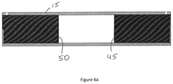
- FIG. 6 a depicts a side, cut away view of the outer tube according to some embodiments presently disclosed.
- FIG. 6 b depicts another side, cut away view of the outer tube according to some embodiments presently disclosed.
- FIG. 7 a depicts a side, cut away view of the expansion chamber assembly according to some embodiments presently disclosed.
- FIG. 7 b depicts another side, cut away view of the expansion chamber assembly according to some embodiments presently disclosed.
- FIG. 8 a depicts an exploded view of the expansion chamber assembly according to some embodiments presently disclosed.
- FIG. 8 b depicts another exploded view of the expansion chamber assembly according to some embodiments presently disclosed.
- FIG. 9 depicts a side, cut away view of the expansion chamber assembly according to some embodiments presently disclosed.
- FIG. 10 a depicts a perspective view of a sound absorbing material according to some embodiments presently disclosed.
- FIG. 10 b depicts a front view of the sound absorbing material shown in FIG. 10 a.
- FIG. 11 a depicts a perspective view of another sound absorbing material according to some embodiments presently disclosed.
- FIG. 11 b depicts a front view of the sound absorbing material shown in FIG. 11 a.
- FIG. 12 a depicts an exploded view of the expansion chamber assembly according to some embodiments presently disclosed.
- FIG. 12 b depicts an assembled view of the expansion chamber shown in FIG. 12 a.
- FIG. 13 a depicts a perspective view of a tool according to some embodiments presently disclosed.
- FIG. 13 b depicts a top view of the tool shown in FIG. 13 a.
- FIG. 14 a depicts a perspective view of another tool according to some embodiments presently disclosed.
- FIG. 14 b depicts a side view of the tool shown in FIG. 14 a.
- the expansion chamber assembly 10 comprises an outer tube 15 , an inner tube 20 , a front cap 25 , and a rear cap 30 .
- the expansion chamber assembly 10 is coupled with an exit end of a barrel 70 (shown in FIG. 2 ) from a firearm.
- the barrel 70 is shown as a rifle barrel, it is to be understood that the expansion chamber assembly 10 can be coupled with a rifle barrel or a handgun barrel.
- the expansion chamber assembly 10 is removably coupled with the barrel 70 or the expansion chamber assembly 10 integral with the barrel 70 .
- the expansion chamber assembly 10 is welded with the exit end of the barrel 70 .
- the expansion chamber assembly 10 may be pinned with the exit end of the barrel 70 .
- the outer tube 15 comprises a first diameter and the inner tube 20 comprises a second diameter, wherein the first diameter is larger than the second diameter. According to some embodiments, the outer tube 15 has a diameter sufficient to accommodate the inner tube 20 . According to some embodiments, the outer tube 15 and the inner tube 20 are hollow cylinders wherein the outer tube 15 has a diameter sufficient to accommodate the inner tube 20 .
- the inner tube 20 is retained inside the outer tube 15 with the front cap 25 and the rear cap 30 as shown in FIGS. 3 a - b .
- the front cap 25 and/or the rear cap 30 are coupled with the outer tube 15 .
- the front cap 25 and/or the rear cap 30 are removably coupled with the outer tube 15 .
- the front cap 25 and/or the rear cap 30 are welded with the outer tube 15 .
- the front cap 25 and/or the rear cap 30 are coupled with the outer tube 15 by one or more fasteners 75 .
- the fasteners 75 are a pin, a screw, a set screw, a full dog point set screw, or a dogleg set screw.
- the front cap 25 comprises a through aperture 26 (as shown in FIGS. 4 a - c ) and an outer thread 28 (as shown in FIGS. 4 a and 4 c ).
- the rear cap 30 comprises a through aperture 31 (as shown in FIGS. 5 a - c ) and an outer thread 32 (as shown in FIGS. 5 a and 5 c ).
- the outer tube 15 comprises a front end 35 and a rear end 40 (shown in FIG. 1 b ).
- the front end 35 may comprise an inner screw threads 45 (shown in cutaway FIGS. 3 a - c ) configured to accommodate and/or engage the outer thread 28 of the front cap 25 .
- the rear end 40 may comprise an inner screw threads 50 (shown in cutaway FIGS. 3 a - c ) configured to accommodate and/or engage the outer thread 32 of the rear cap 30 .
- the inner tube 20 is retained inside the outer tube 15 by screwing the front cap 25 in the front end 35 and screwing the rear cap 30 in the rear end 40 .
- the inner tube 20 is sandwiched inside the outer tube 15 between the front cap 25 and the rear cap 30 .
- the front cap 25 comprises a through aperture 26 (as shown in FIGS. 4 a - c ) with an inner thread (not shown).
- the rear cap 30 comprises a through aperture 31 (as shown in FIGS. 5 a - c ) with an inner thread (not shown).
- the outer tube 15 comprises a front end 35 and a rear end 40 (shown in FIG. 1 b ).
- the front end 35 may comprise an outer screw threads (not shown) configured to accommodate and/or engage the inner thread of the front cap 25 .
- the rear end 40 may comprise an outer screw threads (not shown) configured to accommodate and/or engage the inner thread of the rear cap 30 .
- the inner tube 20 is sandwiched inside the outer tube 15 between the front cap 25 and the rear cap 30 .
- At least a portion of the through aperture 31 of the rear cap 30 comprises an inner thread 34 (shown in FIGS. 5 a and 5 c ) configured to accommodate and/or engage at least a portion of an outer thread 71 (shown in FIG. 12 a ) on the exit end of the barrel 70 .
- the entire through aperture 31 of the rear cap 30 comprises an inner thread 34 (shown in FIGS. 5 a and 5 c ) configured to accommodate at least a portion of an outer thread 71 (shown in FIG. 12 a ) on the exit end of the barrel 70 .
- a bullet fired from a firearm, travels through the firearm's barrel 70 , through the aperture 31 , through the inner tube 20 , and through the aperture 26 of the expansion chamber assembly 10 . Similar to the bullet, the expanding gasses formed by the firing of the bullet also travel through the firearm's barrel 70 and into the expansion chamber assembly 10 as shown by arrow 190 in FIGS. 3 a - b.
- the inner tube 20 comprises one or more through apertures 22 to allow at least another portion of the expanding gasses to enter the outer tube 15 as shown by the arrow 200 in FIGS. 3 a - b .
- the through apertures 22 are round, rectangular, oval, circular or any other geometric shape.
- the expanding gasses located between the outer tube 15 and the inner tube 20 may exit the expansion chamber assembly 10 through one or more exit through apertures (not shown) in the outer tube 15 .
- the expanding gasses located between the outer tube 15 and the inner tube 20 may exit the expansion chamber assembly 10 through one or more exit through apertures 36 in the rear cap 30 as shown by arrow 210 in FIG. 3 a .
- the expanding gasses located between the outer tube 15 and the inner tube 20 may exit the expansion chamber assembly 10 through one or more exit apertures (not shown) in the front cap 25 .
- one or more exit through apertures 36 are in communication with the space between the outer tube 15 and the inner tube 20 .
- the inner screw threads 45 extend into the outer tube 15 (as shown in FIGS. 6 a and 7 a ) and are positioned to interact with the expanding gasses located between the outer tube 15 and the inner tube 20 .
- the inner screw threads 50 extend into the outer tube 15 (as shown in FIGS. 6 a and 7 a ) and are positioned to interact with the expanding gasses located between the outer tube 15 and the inner tube 20 .
- the inner screw threads 45 and the inner screw thread 50 are the same inner screw thread 101 that spans the entire length of the outer tube 15 (as shown in FIGS.
- the inner screw threads 45 , the inner screw threads 50 and/or the inner screw threads 101 are positioned to interact with the expanding gasses located between the outer tube 15 and the inner tube 20 and configured to minimize the sound generated by the bullet fired from the firearm.
- the expansion chamber assembly 10 reduces recoil of the firearm by allowing a portion of the expanding gasses to exit through the apertures 36 located in the rear cap 30 . According to some embodiments, the expansion chamber assembly 10 reduces recoil of the firearm by allowing a portion of the expanding gases to exit the expansion chamber assembly 10 in a direction opposite a direction of travel of the bullet being fired from the firearm.
- the through apertures 36 are 0.125 inches in diameter. According to some embodiments, the through apertures 36 are round, rectangular, oval, circular or any other geometric shape. According to some embodiments, the rear cap 30 comprises eight (8) through apertures 36 . According to some embodiments, the rear cap 30 comprises eight (8) through apertures 36 evenly spaced around the perimeter of the rear cap 30 . According to some embodiments, the through apertures 36 are evenly spaced around the perimeter of the rear cap 30 .
- the expansion chamber assembly 10 is configured to decelerate and cool at least a portion of the expanding gasses thereby reducing the noise and/or flash created when the bullet is fired from the firearm.
- the expansion chamber assembly 10 comprises one or more sound absorbing materials 105 (as shown in FIGS. 8 a - b ) configured to further reduce the noise created when the bullet is fired from the firearm.
- the sound absorbing materials 105 may be hollow cylinders wherein the outer tube 15 has a diameter sufficient to accommodate the sound absorbing materials 105 and the inner tube 20 (as shown in FIG. 9 ).
- the sound absorbing materials 105 may be hollow cylinders with a diameter sufficient to accommodate the inner tube 20 (as shown in FIG. 9 ).
- the absorbing materials 105 comprises a round cross section as shown in FIG. 10 a - b .
- the sound absorbing materials 105 comprises a star shaped cross section as shown in FIG. 11 a - b .
- the sound absorbing materials 105 is a flat, rectangular piece of material that can be rolled into a cylinder.
- the sound absorbing materials 105 is a flat, rectangular piece of material that can be rolled around the inner tube 20 .
- the sound absorbing materials 105 comprises muffler packing material, oil filter packing material, fiberglass material, steel mesh material, steel wool material, foam material, and/or any other type of sound reducing materials.
- a tool 115 may be used to couple the rear cap 30 with the outer tube 15 and/or to couple the expansion chamber assembly 10 with the barrel 70 .
- the tool 115 comprises two or more protrusions 116 positioned and shaped to mate with two or more through apertures 36 .
- the rear cap 30 may be coupled with the outer tube 15 by inserting the two or more protrusions 116 into the apertures 36 and rotating the rear cap 30 about the outer tube 15 so as to engage the inner screw threads 50 with the outer thread 32 of the rear cap 30 .
- the rear cap 30 may be coupled with the barrel 70 by inserting the two or more protrusions 116 into the apertures 36 and rotating the rear cap 30 about the barrel 70 so as to engage the inner screw threads 34 of the rear cap 30 with the barrel 70 's outer thread 71 .
- the tool 115 comprises a substantially semi-circular portion 117 to accommodate the barrel 70 .
- the tool 115 comprises a handle 118 to allow a user to operate the tool 115 .
- a tool 120 may be used to couple the front cap 25 with the outer tube 15 .
- the tool 120 comprises two or more protrusions 122 positioned and shaped to mate with two or more apertures 125 (shown in FIGS. 4 b - c ) in the front cap 25 .
- the front cap 25 may be coupled with the outer tube 15 by inserting the two or more protrusions 122 into the apertures 125 and rotating the front cap 25 about the outer tube 15 so as to engage the inner screw threads 45 with the outer thread 28 of the front cap 25 .
- the tool 120 comprises a handle 123 to allow a user to operate the tool 120 .
- the threads described above are continuous. According to some embodiments, the one or more threads described above are V-Thread, Square Thread, Buttress Thread, Reverse Buttress Thread or a combination of two or more of these threads.
Abstract
A expansion chamber assembly for a firearm is disclosed. The expansion chamber contains an outer tube containing a front end and a rear end, a front cap coupled with the outer tube at the front end, a rear cap coupled with the outer tube at the rear end, an inner tube retained within the outer tube by the front cap and the rear cap, wherein the inner cap contains one or more through apertures to allow expanding gasses to move from the inner tube into the outer tube, and one or more exit apertures to allow expensing gases to exit the expansion chamber assembly.
Description
This application claims the benefit of U.S. Provisional Application No. 62/510,707, filed on May 24, 2017, which is incorporated herein by reference in its entirety.
The present invention relates to a firearm. More particularly, the present invention relates to an expansion chamber assembly for a firearm.
Firing a bullet from a firearm creates a loud noise. The firearm silencers known in the art have various baffles and intermediate spacers that attempt to decrease the noise level created by the firearm when firing a bullet. These silencers are heavy, use lots of different types of parts and/or are difficult to assemble thereby making them expensive to manufacture and quite costly for ultimate consumers. In addition, many prior art silencers do not significantly reduce muzzle flash and/or recoil generated by the firearm when firing the bullet. Therefore, a need exists for a way to reduce noise levels, flash and/or recoil when firing a firearm.
In the following description, like reference numbers are used to identify like elements. Furthermore, the drawings are intended to illustrate major features of exemplary embodiments in a diagrammatic manner. The drawings are not intended to depict every feature of every implementation nor relative dimensions of the depicted elements, and are not drawn to scale.
In the following description, like reference numbers are used to identify like elements. Furthermore, the drawings are intended to illustrate major features of exemplary embodiments in a diagrammatic manner. The drawings are not intended to depict every feature of every implementation nor relative dimensions of the depicted elements, and are not drawn to scale.
In the following description, numerous specific details are set forth to clearly describe various specific embodiments disclosed herein. One skilled in the art, however, will understand that the presently claimed invention may be practiced without all of the specific details discussed below. In other instances, well known features have not been described so as not to obscure the invention.
Referring to FIGS. 1a-b , an expansion chamber assembly 10 is shown according to some embodiments presently disclosed. According to some embodiments, the expansion chamber assembly 10 comprises an outer tube 15, an inner tube 20, a front cap 25, and a rear cap 30. According to some embodiments, the expansion chamber assembly 10 is coupled with an exit end of a barrel 70 (shown in FIG. 2 ) from a firearm. Although the barrel 70 is shown as a rifle barrel, it is to be understood that the expansion chamber assembly 10 can be coupled with a rifle barrel or a handgun barrel. It is to be further understood that the expansion chamber assembly 10 is removably coupled with the barrel 70 or the expansion chamber assembly 10 integral with the barrel 70. According to some embodiments, the expansion chamber assembly 10 is welded with the exit end of the barrel 70. According to some embodiments, the expansion chamber assembly 10 may be pinned with the exit end of the barrel 70.
According to some embodiments, the outer tube 15 comprises a first diameter and the inner tube 20 comprises a second diameter, wherein the first diameter is larger than the second diameter. According to some embodiments, the outer tube 15 has a diameter sufficient to accommodate the inner tube 20. According to some embodiments, the outer tube 15 and the inner tube 20 are hollow cylinders wherein the outer tube 15 has a diameter sufficient to accommodate the inner tube 20.
According to some embodiments, the inner tube 20 is retained inside the outer tube 15 with the front cap 25 and the rear cap 30 as shown in FIGS. 3a-b . According to some embodiments, the front cap 25 and/or the rear cap 30 are coupled with the outer tube 15. According to some embodiments, the front cap 25 and/or the rear cap 30 are removably coupled with the outer tube 15. According to some embodiments, the front cap 25 and/or the rear cap 30 are welded with the outer tube 15. According to some embodiments, the front cap 25 and/or the rear cap 30 are coupled with the outer tube 15 by one or more fasteners 75. According to some embodiments, the fasteners 75 are a pin, a screw, a set screw, a full dog point set screw, or a dogleg set screw.
According to some embodiments, the front cap 25 comprises a through aperture 26 (as shown in FIGS. 4a-c ) and an outer thread 28 (as shown in FIGS. 4a and 4c ). According to some embodiments, the rear cap 30 comprises a through aperture 31 (as shown in FIGS. 5a-c ) and an outer thread 32 (as shown in FIGS. 5a and 5c ). According to some embodiments, the outer tube 15 comprises a front end 35 and a rear end 40 (shown in FIG. 1b ). The front end 35 may comprise an inner screw threads 45 (shown in cutaway FIGS. 3a-c ) configured to accommodate and/or engage the outer thread 28 of the front cap 25. The rear end 40 may comprise an inner screw threads 50 (shown in cutaway FIGS. 3a-c ) configured to accommodate and/or engage the outer thread 32 of the rear cap 30. According to some embodiments, the inner tube 20 is retained inside the outer tube 15 by screwing the front cap 25 in the front end 35 and screwing the rear cap 30 in the rear end 40. According to some embodiments, the inner tube 20 is sandwiched inside the outer tube 15 between the front cap 25 and the rear cap 30.
According to some embodiments, the front cap 25 comprises a through aperture 26 (as shown in FIGS. 4a-c ) with an inner thread (not shown). According to some embodiments, the rear cap 30 comprises a through aperture 31 (as shown in FIGS. 5a-c ) with an inner thread (not shown). According to some embodiments, the outer tube 15 comprises a front end 35 and a rear end 40 (shown in FIG. 1b ). The front end 35 may comprise an outer screw threads (not shown) configured to accommodate and/or engage the inner thread of the front cap 25. The rear end 40 may comprise an outer screw threads (not shown) configured to accommodate and/or engage the inner thread of the rear cap 30. According to some embodiments, the inner tube 20 is sandwiched inside the outer tube 15 between the front cap 25 and the rear cap 30.
According to some embodiments, at least a portion of the through aperture 31 of the rear cap 30 comprises an inner thread 34 (shown in FIGS. 5a and 5c ) configured to accommodate and/or engage at least a portion of an outer thread 71 (shown in FIG. 12a ) on the exit end of the barrel 70. According to some embodiments, the entire through aperture 31 of the rear cap 30 comprises an inner thread 34 (shown in FIGS. 5a and 5c ) configured to accommodate at least a portion of an outer thread 71 (shown in FIG. 12a ) on the exit end of the barrel 70.
According to some embodiments, a bullet, fired from a firearm, travels through the firearm's barrel 70, through the aperture 31, through the inner tube 20, and through the aperture 26 of the expansion chamber assembly 10. Similar to the bullet, the expanding gasses formed by the firing of the bullet also travel through the firearm's barrel 70 and into the expansion chamber assembly 10 as shown by arrow 190 in FIGS. 3a -b.
According to some embodiments, at least a portion of the expanding gasses exit with the bullet through the aperture 26 of the front cap 25 of the expansion chamber assembly 10. According to some embodiments, the inner tube 20 comprises one or more through apertures 22 to allow at least another portion of the expanding gasses to enter the outer tube 15 as shown by the arrow 200 in FIGS. 3a-b . According to some embodiments, the through apertures 22 are round, rectangular, oval, circular or any other geometric shape.
According to some embodiments, the expanding gasses located between the outer tube 15 and the inner tube 20 may exit the expansion chamber assembly 10 through one or more exit through apertures (not shown) in the outer tube 15. According to some embodiments, the expanding gasses located between the outer tube 15 and the inner tube 20 may exit the expansion chamber assembly 10 through one or more exit through apertures 36 in the rear cap 30 as shown by arrow 210 in FIG. 3a . According to some embodiments, the expanding gasses located between the outer tube 15 and the inner tube 20 may exit the expansion chamber assembly 10 through one or more exit apertures (not shown) in the front cap 25. According to some embodiments, one or more exit through apertures 36 are in communication with the space between the outer tube 15 and the inner tube 20.
According to some embodiments, the inner screw threads 45 extend into the outer tube 15 (as shown in FIGS. 6a and 7a ) and are positioned to interact with the expanding gasses located between the outer tube 15 and the inner tube 20. According to some embodiments, the inner screw threads 50 extend into the outer tube 15 (as shown in FIGS. 6a and 7a ) and are positioned to interact with the expanding gasses located between the outer tube 15 and the inner tube 20. According to some embodiments, the inner screw threads 45 and the inner screw thread 50 are the same inner screw thread 101 that spans the entire length of the outer tube 15 (as shown in FIGS. 6b and 7b ) and positioned to interact with the expanding gasses located between the outer tube 15 and the inner tube 20. According to some embodiments, the inner screw threads 45, the inner screw threads 50 and/or the inner screw threads 101 are positioned to interact with the expanding gasses located between the outer tube 15 and the inner tube 20 and configured to minimize the sound generated by the bullet fired from the firearm.
According to some embodiments, the expansion chamber assembly 10 reduces recoil of the firearm by allowing a portion of the expanding gasses to exit through the apertures 36 located in the rear cap 30. According to some embodiments, the expansion chamber assembly 10 reduces recoil of the firearm by allowing a portion of the expanding gases to exit the expansion chamber assembly 10 in a direction opposite a direction of travel of the bullet being fired from the firearm.
According to some embodiments, the through apertures 36 are 0.125 inches in diameter. According to some embodiments, the through apertures 36 are round, rectangular, oval, circular or any other geometric shape. According to some embodiments, the rear cap 30 comprises eight (8) through apertures 36. According to some embodiments, the rear cap 30 comprises eight (8) through apertures 36 evenly spaced around the perimeter of the rear cap 30. According to some embodiments, the through apertures 36 are evenly spaced around the perimeter of the rear cap 30.
According to some embodiments presently disclosed, the expansion chamber assembly 10 is configured to decelerate and cool at least a portion of the expanding gasses thereby reducing the noise and/or flash created when the bullet is fired from the firearm.
According to some embodiments presently disclosed, the expansion chamber assembly 10 comprises one or more sound absorbing materials 105 (as shown in FIGS. 8a-b ) configured to further reduce the noise created when the bullet is fired from the firearm. The sound absorbing materials 105 may be hollow cylinders wherein the outer tube 15 has a diameter sufficient to accommodate the sound absorbing materials 105 and the inner tube 20 (as shown in FIG. 9 ). The sound absorbing materials 105 may be hollow cylinders with a diameter sufficient to accommodate the inner tube 20 (as shown in FIG. 9 ).
According to some embodiments presently disclosed, the absorbing materials 105 comprises a round cross section as shown in FIG. 10a-b . According to some embodiments presently disclosed, the sound absorbing materials 105 comprises a star shaped cross section as shown in FIG. 11a-b . According to some embodiments presently disclosed, the sound absorbing materials 105 is a flat, rectangular piece of material that can be rolled into a cylinder. According to some embodiments presently disclosed, the sound absorbing materials 105 is a flat, rectangular piece of material that can be rolled around the inner tube 20.
According to some embodiments presently disclosed, the sound absorbing materials 105 comprises muffler packing material, oil filter packing material, fiberglass material, steel mesh material, steel wool material, foam material, and/or any other type of sound reducing materials.
Referring to FIGS. 12a-b , a tool 115 may be used to couple the rear cap 30 with the outer tube 15 and/or to couple the expansion chamber assembly 10 with the barrel 70. Referring to FIGS. 13a-b , the tool 115 comprises two or more protrusions 116 positioned and shaped to mate with two or more through apertures 36. The rear cap 30 may be coupled with the outer tube 15 by inserting the two or more protrusions 116 into the apertures 36 and rotating the rear cap 30 about the outer tube 15 so as to engage the inner screw threads 50 with the outer thread 32 of the rear cap 30. The rear cap 30 may be coupled with the barrel 70 by inserting the two or more protrusions 116 into the apertures 36 and rotating the rear cap 30 about the barrel 70 so as to engage the inner screw threads 34 of the rear cap 30 with the barrel 70's outer thread 71. According to some embodiments, the tool 115 comprises a substantially semi-circular portion 117 to accommodate the barrel 70. According to some embodiments, the tool 115 comprises a handle 118 to allow a user to operate the tool 115.
Referring to FIGS. 12a-b , a tool 120 may be used to couple the front cap 25 with the outer tube 15. Referring to FIGS. 14a-b , the tool 120 comprises two or more protrusions 122 positioned and shaped to mate with two or more apertures 125 (shown in FIGS. 4b-c ) in the front cap 25. The front cap 25 may be coupled with the outer tube 15 by inserting the two or more protrusions 122 into the apertures 125 and rotating the front cap 25 about the outer tube 15 so as to engage the inner screw threads 45 with the outer thread 28 of the front cap 25. According to some embodiments, the tool 120 comprises a handle 123 to allow a user to operate the tool 120.
According to some embodiments, the threads described above are continuous. According to some embodiments, the one or more threads described above are V-Thread, Square Thread, Buttress Thread, Reverse Buttress Thread or a combination of two or more of these threads.
While several illustrative embodiments of the invention have been shown and described, numerous variations and alternative embodiments will occur to those skilled in the art. Such variations and alternative embodiments are contemplated, and can be made without departing from the scope of the invention as defined in the appended claims.
As used in this specification and the appended claims, the singular forms “a,” “an,” and “the” include plural referents unless the content clearly dictates otherwise. The term “plurality” includes two or more referents unless the content clearly dictates otherwise. Unless defined otherwise, all technical and scientific terms used herein have the same meaning as commonly understood by one of ordinary skill in the art to which the disclosure pertains.
Claims (10)
1. A expansion chamber assembly for a firearm, the expansion chamber assembly comprising:
an outer tube comprising a front end and a rear end;
a front cap coupled with the outer tube at the front end;
a rear cap coupled with the outer tube at the rear end, wherein the rear cap comprises an inner thread configured to engage at least a portion of an outer thread on an exit end of a barrel; and
an inner tube removably retained within the outer tube by the front cap and the rear cap, wherein the inner tube comprises one or more through apertures to allow a portion of expanding gasses to move from the inner tube into the outer tube;
wherein the portion of expanding gases move from the inner tube into the outer tube through one or more through apertures;
wherein the portion of expanding gasses move from the outer tube to outside the expansion chamber assembly directly through one or more exit apertures located in the rear cap.
2. The expansion chamber assembly of claim 1 further comprising a sound absorbing materials positioned between the inner tube and the outer tube.
3. The expansion chamber assembly of claim 1 , wherein the one or more through apertures allow expanding gasses to move from the inner tube directly into the outer tube.
4. A expansion chamber assembly for a firearm, the expansion chamber assembly comprising:
an outer tube comprising a front end and a rear end;
a front cap coupled with the outer tube at the front end;
a rear cap coupled with the outer tube at the rear end; and
an inner tube removably retained within the outer tube by the front cap and the rear cap, wherein the inner tube is positioned between the front cap and the rear cap;
wherein the rear cap comprises a first through aperture to allow expanding gasses to move from a barrel into the inner tube;
wherein the inner tube comprises one or more through apertures to allow a portion of the expanding gasses to move from the inner tube into the outer tube; and
wherein the rear cap comprises one or more exit apertures to allow the portion of the expanding gases to exit the expansion chamber assembly.
5. The expansion chamber assembly of claim 4 , wherein expanding gasses moving from the barrel into the inner tube travel in a direction that is opposite to the portion of the expanding gases that exit the expansion chamber assembly through the one or more exit apertures.
6. The expansion chamber assembly of claim 4 , wherein the portion of the expanding gases exit the expansion chamber assembly adjacent to where the expanding gasses move from the barrel into the inner tube.
7. The expansion chamber assembly of claim 1 , wherein the rear cap comprises an outer thread for removably coupling with an inner thread of the outer tube.
8. The expansion chamber assembly of claim 4 , wherein the rear cap comprises an outer thread for removably coupling with an inner thread of the outer tube.
9. The expansion chamber assembly of claim 1 , wherein the front cap comprises an outer thread for removably coupling with an inner thread of the outer tube.
10. The expansion chamber assembly of claim 4 , wherein the front cap comprises an outer thread for removably coupling with an inner thread of the outer tube.
Priority Applications (2)
| Application Number | Priority Date | Filing Date | Title |
|---|---|---|---|
| US15/987,833 US11268776B1 (en) | 2017-05-24 | 2018-05-23 | Expansion chamber assembly and a method of manufacturing the same |
| US17/590,708 US20230003478A1 (en) | 2017-05-24 | 2022-02-01 | Expansion chamber assembly and a method of manufacturing the same |
Applications Claiming Priority (2)
| Application Number | Priority Date | Filing Date | Title |
|---|---|---|---|
| US201762510707P | 2017-05-24 | 2017-05-24 | |
| US15/987,833 US11268776B1 (en) | 2017-05-24 | 2018-05-23 | Expansion chamber assembly and a method of manufacturing the same |
Related Child Applications (1)
| Application Number | Title | Priority Date | Filing Date |
|---|---|---|---|
| US17/590,708 Continuation US20230003478A1 (en) | 2017-05-24 | 2022-02-01 | Expansion chamber assembly and a method of manufacturing the same |
Publications (1)
| Publication Number | Publication Date |
|---|---|
| US11268776B1 true US11268776B1 (en) | 2022-03-08 |
Family
ID=80473305
Family Applications (2)
| Application Number | Title | Priority Date | Filing Date |
|---|---|---|---|
| US15/987,833 Active US11268776B1 (en) | 2017-05-24 | 2018-05-23 | Expansion chamber assembly and a method of manufacturing the same |
| US17/590,708 Pending US20230003478A1 (en) | 2017-05-24 | 2022-02-01 | Expansion chamber assembly and a method of manufacturing the same |
Family Applications After (1)
| Application Number | Title | Priority Date | Filing Date |
|---|---|---|---|
| US17/590,708 Pending US20230003478A1 (en) | 2017-05-24 | 2022-02-01 | Expansion chamber assembly and a method of manufacturing the same |
Country Status (1)
| Country | Link |
|---|---|
| US (2) | US11268776B1 (en) |
Cited By (5)
| Publication number | Priority date | Publication date | Assignee | Title |
|---|---|---|---|---|
| US20210356224A1 (en) * | 2019-09-05 | 2021-11-18 | Centre Firearms Co., Inc. | Monolithic noise suppression device with cooling features |
| US20220349667A1 (en) * | 2019-07-10 | 2022-11-03 | American Nano Llc. | Sound suppressors and suppressor sleeves incorporating silica fibers |
| US20230003478A1 (en) * | 2017-05-24 | 2023-01-05 | F.M. Products Inc | Expansion chamber assembly and a method of manufacturing the same |
| US11598610B2 (en) * | 2019-10-15 | 2023-03-07 | Daniel Dentler | Mounting device for a telescopic sight on a hunting or sports weapon with at least one resilient stay bolt |
| US20240044600A1 (en) * | 2022-08-04 | 2024-02-08 | WHG Properties, LLC | Firearm suppressor |
Citations (54)
| Publication number | Priority date | Publication date | Assignee | Title |
|---|---|---|---|---|
| US4307652A (en) * | 1979-11-02 | 1981-12-29 | Leonard Witt | Muzzle-guard for firearms |
| US20030010187A1 (en) * | 2001-07-13 | 2003-01-16 | Muirhead Todd A. | Heat sink for firearm barrels and method for attachment and use |
| US20030145718A1 (en) * | 2000-02-15 | 2003-08-07 | Hausken Hans Petter | Firearm silencer |
| US20110186377A1 (en) * | 2008-02-20 | 2011-08-04 | Korey Kline | Firearm silencer and methods for manufacturing and fastening a silencer onto a firearm |
| US8025003B1 (en) * | 2009-10-14 | 2011-09-27 | The United States Of America As Represented By The Secretary Of The Navy | Fluted firearm barrel |
| US20120011757A1 (en) * | 2008-04-14 | 2012-01-19 | Yost Bill R | Shotgun gas exchanger |
| US20120152649A1 (en) * | 2010-12-21 | 2012-06-21 | Larue Mark C | Suppressor for attachment to firearm barrel |
| US8261651B2 (en) * | 2007-01-12 | 2012-09-11 | Gamo Outdoor, S.L. | Air or fire rifle with noise dampener |
| US20130180797A1 (en) * | 2012-01-12 | 2013-07-18 | Surefire, Llc | Firearm sound suppressor with blast deflector |
| US20130319790A1 (en) * | 2010-10-05 | 2013-12-05 | John William Bladen | Sound suppressor for firearms |
| US20140059913A1 (en) * | 2012-03-14 | 2014-03-06 | Advanced Innovation and Manufacturing, Inc. | Suppressor sleeves and heat resistant weapon accessories |
| US20140224574A1 (en) * | 2013-01-03 | 2014-08-14 | Gemtech | Weapon Silencers and Baffles for Weapon Silencers |
| US20140231168A1 (en) * | 2003-11-06 | 2014-08-21 | Surefire, Llc | Firearm sound suppressor |
| US20140262605A1 (en) * | 2013-03-15 | 2014-09-18 | Center Firearms Co., Inc. | Monolithic noise suppression device for firearm |
| US20150001001A1 (en) * | 2012-12-21 | 2015-01-01 | Bert John WILSON | Suppressors and their methods of manufacture |
| US8939057B1 (en) * | 2013-09-12 | 2015-01-27 | Richard A. Edsall | Firearm suppressor |
| US20150090105A1 (en) * | 2013-09-30 | 2015-04-02 | William Pope Pace | Firearm Receiver Having an Integral Suppressor Assembly |
| US8997621B1 (en) * | 2014-08-29 | 2015-04-07 | Gemini Technologies | Quick mount adapter for firearm suppressor |
| US20150136519A1 (en) * | 2013-11-19 | 2015-05-21 | FN America, LLC | Sound Suppressor for a Firearm |
| US20150241159A1 (en) * | 2012-03-14 | 2015-08-27 | Frank J. Michal | Barrel and suppressor sleeves and heat resistant weapon accessories |
| US20150260472A1 (en) * | 2013-12-05 | 2015-09-17 | Ra Brands, L.L.C. | Silencer with improved mount |
| US20150285575A1 (en) * | 2015-05-29 | 2015-10-08 | Michael L. Sclafani | Firearm Silencer with a Replacement Core |
| US20150308776A1 (en) * | 2013-12-30 | 2015-10-29 | Smith Enterprise, Inc. | Methods and apparatus for flash suppression |
| US20150354422A1 (en) * | 2014-06-09 | 2015-12-10 | Emporeum Plastics, LLC | Porous Matrix Sound Suppressor |
| US20150377577A1 (en) * | 2014-06-30 | 2015-12-31 | Steven Michael Pappas | Harmonically De-Tuned Flash Suppressor for Firearms |
| US20160010935A1 (en) * | 2013-12-30 | 2016-01-14 | The United States Of America As Represented By The Secretary Of The Navy | Integral multi-chambered valved suppressor |
| US20160018179A1 (en) * | 2014-07-17 | 2016-01-21 | Freedom Armory Inc. | Suppressor with configurable baffles |
| US20160054086A1 (en) * | 2014-08-21 | 2016-02-25 | William Westlake | Gun sound moderator |
| US20160061551A1 (en) * | 2014-08-28 | 2016-03-03 | Delta P Design, Inc. | Firearm suppressor insert retained by encapsulating parent material |
| US20160123689A1 (en) * | 2013-05-29 | 2016-05-05 | Hiromi Maeda | Muzzle brake and firearm |
| US20160161203A1 (en) * | 2012-12-21 | 2016-06-09 | Bert John WILSON | Suppressors and their methods of manufacture |
| US20160209149A1 (en) * | 2013-07-05 | 2016-07-21 | Andreas STEINDL | Silencer |
| US9500427B1 (en) * | 2015-10-29 | 2016-11-22 | Mark C. LaRue | Firearm sound and flash suppressor having low pressure discharge |
| US9658010B1 (en) * | 2014-10-13 | 2017-05-23 | Paul Oglesby | Heat shielding and thermal venting system |
| US9677839B1 (en) * | 2016-06-16 | 2017-06-13 | Joseph Phoenix | Firearm suppressor and methods of manufacturing the same |
| US20170199002A1 (en) * | 2016-01-13 | 2017-07-13 | Fortis Manufacturing, Inc. | Systems and methods for a blast control device for a firearm |
| US20180031346A1 (en) * | 2013-03-15 | 2018-02-01 | Centre Firearms Co., Inc. | Monolithic noise suppression device for firearm with structural connecting core |
| US20180038663A1 (en) * | 2016-08-08 | 2018-02-08 | Mark C. LaRue | Suppressed upper receiver group having locking suppressor with through brake |
| US20180058789A1 (en) * | 2016-08-03 | 2018-03-01 | Robert Lindsey Dorne | Modular gun silencer |
| US20180252489A1 (en) * | 2017-03-03 | 2018-09-06 | CGS Group. LLC | Suppressor with varying core diameter |
| US10107581B2 (en) * | 2016-01-17 | 2018-10-23 | Ascendance International LLC | Firearm suppression device |
| US20180321008A1 (en) * | 2017-05-08 | 2018-11-08 | AMTAC, Inc ., d.b.a. AMTAC Suppressors | Firearm suppressor |
| US10126084B1 (en) * | 2014-10-13 | 2018-11-13 | Paul Oglesby | 3-D printed suppressor element |
| US20190017767A1 (en) * | 2017-06-26 | 2019-01-17 | Travis Griffis | Firearm sound suppressor |
| US20190017768A1 (en) * | 2017-03-23 | 2019-01-17 | Gerald R. Thomas | Suppressor for firearms |
| US20190033030A1 (en) * | 2016-01-18 | 2019-01-31 | Prime Manufacturing Group Limited (BVI) | Device for releasably mounting a silencer and silencer arrangement |
| US10234230B1 (en) * | 2015-11-09 | 2019-03-19 | Paul A. Oglesby | Flash suppressor and flash suppressor assembly |
| US10337819B1 (en) * | 2017-01-16 | 2019-07-02 | David B. Stark | Reduction of first shot noise in firearm sound suppressors |
| US10502513B2 (en) * | 2017-12-20 | 2019-12-10 | Benjamin R. Ellison | Firearm sound suppressor and methods of manufacture |
| US20200072571A1 (en) * | 2018-09-04 | 2020-03-05 | Centre Firearms Co., Inc. | Monolithic noise suppression device with purposely induced porosity for firearm |
| US20200141679A1 (en) * | 2016-01-17 | 2020-05-07 | Ascendance International, LLC | Firearm suppression device |
| US20200166304A1 (en) * | 2018-10-11 | 2020-05-28 | Scott R. Martin | Integrally suppressed firearm utilizing segregated expansion chambers |
| US20200173751A1 (en) * | 2018-12-04 | 2020-06-04 | Mad Minute Ip Holdco Inc. | Modular gun silencer with heat dissipator |
| US20200232740A1 (en) * | 2019-01-18 | 2020-07-23 | Surefire, Llc | Recoil booster for firearm suppressor |
Family Cites Families (10)
| Publication number | Priority date | Publication date | Assignee | Title |
|---|---|---|---|---|
| US20160003570A1 (en) * | 2014-07-07 | 2016-01-07 | Eric T. Tonkin | Weapon Barrel Having Integrated Suppressor |
| RU2670666C9 (en) * | 2015-02-05 | 2018-12-19 | Фар Лиг С.Р.Л. | Automatic submachine gun, in which the energy of receiving is used, containing two operating leverages of the trigger, one of which is related to the single fire regime, and another – with the mode of shooting in rounds |
| US10386146B2 (en) * | 2016-02-22 | 2019-08-20 | Radical Firearms, LLC | Handguard and barrel assembly with sound suppressor for a firearm |
| US10222162B2 (en) * | 2016-04-13 | 2019-03-05 | APD Manufacturing, LLC | Firearm sound suppressor |
| BR112018073292B1 (en) * | 2016-05-12 | 2022-06-28 | Dieter Christandl | MUFFLER FOR A FIREGUN |
| US10731940B2 (en) * | 2016-09-26 | 2020-08-04 | U.S. Arms Company Llc | Muzzle brake device |
| US11933566B2 (en) * | 2017-01-17 | 2024-03-19 | Bernard De Sousa | Ported baffle firearm suppressor |
| US11268776B1 (en) * | 2017-05-24 | 2022-03-08 | F.M. Products Inc | Expansion chamber assembly and a method of manufacturing the same |
| US10890403B2 (en) * | 2018-01-23 | 2021-01-12 | Delta P Design, Inc. | Suppressor with blowout panel |
| US11118856B2 (en) * | 2018-02-09 | 2021-09-14 | DK Precision Outdoor, LLC | Self-cleaning firearms suppressor |
-
2018
- 2018-05-23 US US15/987,833 patent/US11268776B1/en active Active
-
2022
- 2022-02-01 US US17/590,708 patent/US20230003478A1/en active Pending
Patent Citations (56)
| Publication number | Priority date | Publication date | Assignee | Title |
|---|---|---|---|---|
| US4307652A (en) * | 1979-11-02 | 1981-12-29 | Leonard Witt | Muzzle-guard for firearms |
| US20030145718A1 (en) * | 2000-02-15 | 2003-08-07 | Hausken Hans Petter | Firearm silencer |
| US20030010187A1 (en) * | 2001-07-13 | 2003-01-16 | Muirhead Todd A. | Heat sink for firearm barrels and method for attachment and use |
| US20140231168A1 (en) * | 2003-11-06 | 2014-08-21 | Surefire, Llc | Firearm sound suppressor |
| US8261651B2 (en) * | 2007-01-12 | 2012-09-11 | Gamo Outdoor, S.L. | Air or fire rifle with noise dampener |
| US20110186377A1 (en) * | 2008-02-20 | 2011-08-04 | Korey Kline | Firearm silencer and methods for manufacturing and fastening a silencer onto a firearm |
| US20120011757A1 (en) * | 2008-04-14 | 2012-01-19 | Yost Bill R | Shotgun gas exchanger |
| US8025003B1 (en) * | 2009-10-14 | 2011-09-27 | The United States Of America As Represented By The Secretary Of The Navy | Fluted firearm barrel |
| US20130319790A1 (en) * | 2010-10-05 | 2013-12-05 | John William Bladen | Sound suppressor for firearms |
| US20120152649A1 (en) * | 2010-12-21 | 2012-06-21 | Larue Mark C | Suppressor for attachment to firearm barrel |
| US20130180797A1 (en) * | 2012-01-12 | 2013-07-18 | Surefire, Llc | Firearm sound suppressor with blast deflector |
| US20150241159A1 (en) * | 2012-03-14 | 2015-08-27 | Frank J. Michal | Barrel and suppressor sleeves and heat resistant weapon accessories |
| US20140059913A1 (en) * | 2012-03-14 | 2014-03-06 | Advanced Innovation and Manufacturing, Inc. | Suppressor sleeves and heat resistant weapon accessories |
| US20150001001A1 (en) * | 2012-12-21 | 2015-01-01 | Bert John WILSON | Suppressors and their methods of manufacture |
| US20160161203A1 (en) * | 2012-12-21 | 2016-06-09 | Bert John WILSON | Suppressors and their methods of manufacture |
| US9102010B2 (en) * | 2012-12-21 | 2015-08-11 | Bert John WILSON | Suppressors and their methods of manufacture |
| US20140224574A1 (en) * | 2013-01-03 | 2014-08-14 | Gemtech | Weapon Silencers and Baffles for Weapon Silencers |
| US9982959B2 (en) * | 2013-03-15 | 2018-05-29 | Centre Firearms Co., Inc. | Monolithic noise suppression device for firearm |
| US20140262605A1 (en) * | 2013-03-15 | 2014-09-18 | Center Firearms Co., Inc. | Monolithic noise suppression device for firearm |
| US20180031346A1 (en) * | 2013-03-15 | 2018-02-01 | Centre Firearms Co., Inc. | Monolithic noise suppression device for firearm with structural connecting core |
| US20160123689A1 (en) * | 2013-05-29 | 2016-05-05 | Hiromi Maeda | Muzzle brake and firearm |
| US20160209149A1 (en) * | 2013-07-05 | 2016-07-21 | Andreas STEINDL | Silencer |
| US8939057B1 (en) * | 2013-09-12 | 2015-01-27 | Richard A. Edsall | Firearm suppressor |
| US20150090105A1 (en) * | 2013-09-30 | 2015-04-02 | William Pope Pace | Firearm Receiver Having an Integral Suppressor Assembly |
| US20150136519A1 (en) * | 2013-11-19 | 2015-05-21 | FN America, LLC | Sound Suppressor for a Firearm |
| US20150260472A1 (en) * | 2013-12-05 | 2015-09-17 | Ra Brands, L.L.C. | Silencer with improved mount |
| US20160010935A1 (en) * | 2013-12-30 | 2016-01-14 | The United States Of America As Represented By The Secretary Of The Navy | Integral multi-chambered valved suppressor |
| US20150308776A1 (en) * | 2013-12-30 | 2015-10-29 | Smith Enterprise, Inc. | Methods and apparatus for flash suppression |
| US20150354422A1 (en) * | 2014-06-09 | 2015-12-10 | Emporeum Plastics, LLC | Porous Matrix Sound Suppressor |
| US20150377577A1 (en) * | 2014-06-30 | 2015-12-31 | Steven Michael Pappas | Harmonically De-Tuned Flash Suppressor for Firearms |
| US20160018179A1 (en) * | 2014-07-17 | 2016-01-21 | Freedom Armory Inc. | Suppressor with configurable baffles |
| US20160054086A1 (en) * | 2014-08-21 | 2016-02-25 | William Westlake | Gun sound moderator |
| US20160061551A1 (en) * | 2014-08-28 | 2016-03-03 | Delta P Design, Inc. | Firearm suppressor insert retained by encapsulating parent material |
| US8997621B1 (en) * | 2014-08-29 | 2015-04-07 | Gemini Technologies | Quick mount adapter for firearm suppressor |
| US9658010B1 (en) * | 2014-10-13 | 2017-05-23 | Paul Oglesby | Heat shielding and thermal venting system |
| US10126084B1 (en) * | 2014-10-13 | 2018-11-13 | Paul Oglesby | 3-D printed suppressor element |
| US20150285575A1 (en) * | 2015-05-29 | 2015-10-08 | Michael L. Sclafani | Firearm Silencer with a Replacement Core |
| US9500427B1 (en) * | 2015-10-29 | 2016-11-22 | Mark C. LaRue | Firearm sound and flash suppressor having low pressure discharge |
| US10234230B1 (en) * | 2015-11-09 | 2019-03-19 | Paul A. Oglesby | Flash suppressor and flash suppressor assembly |
| US20170199002A1 (en) * | 2016-01-13 | 2017-07-13 | Fortis Manufacturing, Inc. | Systems and methods for a blast control device for a firearm |
| US20200141679A1 (en) * | 2016-01-17 | 2020-05-07 | Ascendance International, LLC | Firearm suppression device |
| US10107581B2 (en) * | 2016-01-17 | 2018-10-23 | Ascendance International LLC | Firearm suppression device |
| US20190033030A1 (en) * | 2016-01-18 | 2019-01-31 | Prime Manufacturing Group Limited (BVI) | Device for releasably mounting a silencer and silencer arrangement |
| US9677839B1 (en) * | 2016-06-16 | 2017-06-13 | Joseph Phoenix | Firearm suppressor and methods of manufacturing the same |
| US20180058789A1 (en) * | 2016-08-03 | 2018-03-01 | Robert Lindsey Dorne | Modular gun silencer |
| US20180038663A1 (en) * | 2016-08-08 | 2018-02-08 | Mark C. LaRue | Suppressed upper receiver group having locking suppressor with through brake |
| US10337819B1 (en) * | 2017-01-16 | 2019-07-02 | David B. Stark | Reduction of first shot noise in firearm sound suppressors |
| US20180252489A1 (en) * | 2017-03-03 | 2018-09-06 | CGS Group. LLC | Suppressor with varying core diameter |
| US20190017768A1 (en) * | 2017-03-23 | 2019-01-17 | Gerald R. Thomas | Suppressor for firearms |
| US20180321008A1 (en) * | 2017-05-08 | 2018-11-08 | AMTAC, Inc ., d.b.a. AMTAC Suppressors | Firearm suppressor |
| US20190017767A1 (en) * | 2017-06-26 | 2019-01-17 | Travis Griffis | Firearm sound suppressor |
| US10502513B2 (en) * | 2017-12-20 | 2019-12-10 | Benjamin R. Ellison | Firearm sound suppressor and methods of manufacture |
| US20200072571A1 (en) * | 2018-09-04 | 2020-03-05 | Centre Firearms Co., Inc. | Monolithic noise suppression device with purposely induced porosity for firearm |
| US20200166304A1 (en) * | 2018-10-11 | 2020-05-28 | Scott R. Martin | Integrally suppressed firearm utilizing segregated expansion chambers |
| US20200173751A1 (en) * | 2018-12-04 | 2020-06-04 | Mad Minute Ip Holdco Inc. | Modular gun silencer with heat dissipator |
| US20200232740A1 (en) * | 2019-01-18 | 2020-07-23 | Surefire, Llc | Recoil booster for firearm suppressor |
Cited By (7)
| Publication number | Priority date | Publication date | Assignee | Title |
|---|---|---|---|---|
| US20230003478A1 (en) * | 2017-05-24 | 2023-01-05 | F.M. Products Inc | Expansion chamber assembly and a method of manufacturing the same |
| US20220349667A1 (en) * | 2019-07-10 | 2022-11-03 | American Nano Llc. | Sound suppressors and suppressor sleeves incorporating silica fibers |
| US20210356224A1 (en) * | 2019-09-05 | 2021-11-18 | Centre Firearms Co., Inc. | Monolithic noise suppression device with cooling features |
| US11725897B2 (en) * | 2019-09-05 | 2023-08-15 | Centre Firearms Co., Inc. | Monolithic noise suppression device with cooling features |
| US20230296342A1 (en) * | 2019-09-05 | 2023-09-21 | Centre Firearms Co., Inc. | Monolithic noise suppression device with purposely induced porosity for firearm |
| US11598610B2 (en) * | 2019-10-15 | 2023-03-07 | Daniel Dentler | Mounting device for a telescopic sight on a hunting or sports weapon with at least one resilient stay bolt |
| US20240044600A1 (en) * | 2022-08-04 | 2024-02-08 | WHG Properties, LLC | Firearm suppressor |
Also Published As
| Publication number | Publication date |
|---|---|
| US20230003478A1 (en) | 2023-01-05 |
Similar Documents
| Publication | Publication Date | Title |
|---|---|---|
| US11268776B1 (en) | Expansion chamber assembly and a method of manufacturing the same | |
| USRE47932E1 (en) | Sound suppressor | |
| US9097482B1 (en) | Sound suppressor for a firearm | |
| US9261317B2 (en) | Suppressor assembly for a firearm | |
| US10393463B1 (en) | Self-tightening suppressor mount and system | |
| US9709355B2 (en) | Recoil compensator for firearm | |
| US10480885B2 (en) | Sound suppressor | |
| US20150253099A1 (en) | Baffles for firearm noise suppressor | |
| US8991550B2 (en) | Baffle for use in a sound suppressor for a firearm | |
| US9228789B1 (en) | Muzzle brake | |
| EP2867607B1 (en) | Silencer for a firearm | |
| US8015908B2 (en) | Firearm silencer and methods for manufacturing and fastening a silencer onto a firearm | |
| US9080829B1 (en) | Stabilizer brake for firearm | |
| US7905171B1 (en) | Noise reducing booster insert | |
| US20120246987A1 (en) | Recoil, sound and flash suppressor | |
| US11609059B2 (en) | Firearm suppressor | |
| US20210172694A1 (en) | Modular firearm muzzle device | |
| US20200182578A1 (en) | Multi-Configuration Suppressor | |
| EP2977708A1 (en) | Sound suppressor for a firearm | |
| DE102011010639B4 (en) | Muffler for a handgun | |
| US11486669B2 (en) | Baffle component for a sound suppressor | |
| US10845150B1 (en) | Flash suppressor | |
| US20100180758A1 (en) | Extreme choke | |
| EP3992566B1 (en) | Silencer for a handgun | |
| DE202013004331U1 (en) | Silencer with impulse transmitter for handguns (long and short weapons) |
Legal Events
| Date | Code | Title | Description |
|---|---|---|---|
| FEPP | Fee payment procedure |
Free format text: ENTITY STATUS SET TO UNDISCOUNTED (ORIGINAL EVENT CODE: BIG.); ENTITY STATUS OF PATENT OWNER: SMALL ENTITY |
|
| FEPP | Fee payment procedure |
Free format text: ENTITY STATUS SET TO SMALL (ORIGINAL EVENT CODE: SMAL); ENTITY STATUS OF PATENT OWNER: SMALL ENTITY |
|
| STCF | Information on status: patent grant |
Free format text: PATENTED CASE |