US11230062B2 - Method and apparatus for additive manufacturing - Google Patents
Method and apparatus for additive manufacturing Download PDFInfo
- Publication number
- US11230062B2 US11230062B2 US16/280,851 US201916280851A US11230062B2 US 11230062 B2 US11230062 B2 US 11230062B2 US 201916280851 A US201916280851 A US 201916280851A US 11230062 B2 US11230062 B2 US 11230062B2
- Authority
- US
- United States
- Prior art keywords
- tooling
- scanning
- spheres
- scanned
- scanner
- Prior art date
- Legal status (The legal status is an assumption and is not a legal conclusion. Google has not performed a legal analysis and makes no representation as to the accuracy of the status listed.)
- Active
Links
Images


Classifications
-
- B—PERFORMING OPERATIONS; TRANSPORTING
- B29—WORKING OF PLASTICS; WORKING OF SUBSTANCES IN A PLASTIC STATE IN GENERAL
- B29C—SHAPING OR JOINING OF PLASTICS; SHAPING OF MATERIAL IN A PLASTIC STATE, NOT OTHERWISE PROVIDED FOR; AFTER-TREATMENT OF THE SHAPED PRODUCTS, e.g. REPAIRING
- B29C64/00—Additive manufacturing, i.e. manufacturing of three-dimensional [3D] objects by additive deposition, additive agglomeration or additive layering, e.g. by 3D printing, stereolithography or selective laser sintering
- B29C64/30—Auxiliary operations or equipment
- B29C64/386—Data acquisition or data processing for additive manufacturing
- B29C64/393—Data acquisition or data processing for additive manufacturing for controlling or regulating additive manufacturing processes
-
- B—PERFORMING OPERATIONS; TRANSPORTING
- B29—WORKING OF PLASTICS; WORKING OF SUBSTANCES IN A PLASTIC STATE IN GENERAL
- B29C—SHAPING OR JOINING OF PLASTICS; SHAPING OF MATERIAL IN A PLASTIC STATE, NOT OTHERWISE PROVIDED FOR; AFTER-TREATMENT OF THE SHAPED PRODUCTS, e.g. REPAIRING
- B29C64/00—Additive manufacturing, i.e. manufacturing of three-dimensional [3D] objects by additive deposition, additive agglomeration or additive layering, e.g. by 3D printing, stereolithography or selective laser sintering
- B29C64/30—Auxiliary operations or equipment
- B29C64/386—Data acquisition or data processing for additive manufacturing
-
- B—PERFORMING OPERATIONS; TRANSPORTING
- B23—MACHINE TOOLS; METAL-WORKING NOT OTHERWISE PROVIDED FOR
- B23Q—DETAILS, COMPONENTS, OR ACCESSORIES FOR MACHINE TOOLS, e.g. ARRANGEMENTS FOR COPYING OR CONTROLLING; MACHINE TOOLS IN GENERAL CHARACTERISED BY THE CONSTRUCTION OF PARTICULAR DETAILS OR COMPONENTS; COMBINATIONS OR ASSOCIATIONS OF METAL-WORKING MACHINES, NOT DIRECTED TO A PARTICULAR RESULT
- B23Q17/00—Arrangements for observing, indicating or measuring on machine tools
- B23Q17/20—Arrangements for observing, indicating or measuring on machine tools for indicating or measuring workpiece characteristics, e.g. contour, dimension, hardness
-
- B—PERFORMING OPERATIONS; TRANSPORTING
- B23—MACHINE TOOLS; METAL-WORKING NOT OTHERWISE PROVIDED FOR
- B23Q—DETAILS, COMPONENTS, OR ACCESSORIES FOR MACHINE TOOLS, e.g. ARRANGEMENTS FOR COPYING OR CONTROLLING; MACHINE TOOLS IN GENERAL CHARACTERISED BY THE CONSTRUCTION OF PARTICULAR DETAILS OR COMPONENTS; COMBINATIONS OR ASSOCIATIONS OF METAL-WORKING MACHINES, NOT DIRECTED TO A PARTICULAR RESULT
- B23Q17/00—Arrangements for observing, indicating or measuring on machine tools
- B23Q17/22—Arrangements for observing, indicating or measuring on machine tools for indicating or measuring existing or desired position of tool or work
- B23Q17/2233—Arrangements for observing, indicating or measuring on machine tools for indicating or measuring existing or desired position of tool or work for adjusting the tool relative to the workpiece
-
- B—PERFORMING OPERATIONS; TRANSPORTING
- B23—MACHINE TOOLS; METAL-WORKING NOT OTHERWISE PROVIDED FOR
- B23Q—DETAILS, COMPONENTS, OR ACCESSORIES FOR MACHINE TOOLS, e.g. ARRANGEMENTS FOR COPYING OR CONTROLLING; MACHINE TOOLS IN GENERAL CHARACTERISED BY THE CONSTRUCTION OF PARTICULAR DETAILS OR COMPONENTS; COMBINATIONS OR ASSOCIATIONS OF METAL-WORKING MACHINES, NOT DIRECTED TO A PARTICULAR RESULT
- B23Q17/00—Arrangements for observing, indicating or measuring on machine tools
- B23Q17/24—Arrangements for observing, indicating or measuring on machine tools using optics or electromagnetic waves
- B23Q17/2428—Arrangements for observing, indicating or measuring on machine tools using optics or electromagnetic waves for measuring existing positions of tools or workpieces
-
- B—PERFORMING OPERATIONS; TRANSPORTING
- B23—MACHINE TOOLS; METAL-WORKING NOT OTHERWISE PROVIDED FOR
- B23Q—DETAILS, COMPONENTS, OR ACCESSORIES FOR MACHINE TOOLS, e.g. ARRANGEMENTS FOR COPYING OR CONTROLLING; MACHINE TOOLS IN GENERAL CHARACTERISED BY THE CONSTRUCTION OF PARTICULAR DETAILS OR COMPONENTS; COMBINATIONS OR ASSOCIATIONS OF METAL-WORKING MACHINES, NOT DIRECTED TO A PARTICULAR RESULT
- B23Q17/00—Arrangements for observing, indicating or measuring on machine tools
- B23Q17/24—Arrangements for observing, indicating or measuring on machine tools using optics or electromagnetic waves
- B23Q17/2452—Arrangements for observing, indicating or measuring on machine tools using optics or electromagnetic waves for measuring features or for detecting a condition of machine parts, tools or workpieces
- B23Q17/2471—Arrangements for observing, indicating or measuring on machine tools using optics or electromagnetic waves for measuring features or for detecting a condition of machine parts, tools or workpieces of workpieces
-
- B—PERFORMING OPERATIONS; TRANSPORTING
- B29—WORKING OF PLASTICS; WORKING OF SUBSTANCES IN A PLASTIC STATE IN GENERAL
- B29C—SHAPING OR JOINING OF PLASTICS; SHAPING OF MATERIAL IN A PLASTIC STATE, NOT OTHERWISE PROVIDED FOR; AFTER-TREATMENT OF THE SHAPED PRODUCTS, e.g. REPAIRING
- B29C64/00—Additive manufacturing, i.e. manufacturing of three-dimensional [3D] objects by additive deposition, additive agglomeration or additive layering, e.g. by 3D printing, stereolithography or selective laser sintering
- B29C64/10—Processes of additive manufacturing
- B29C64/188—Processes of additive manufacturing involving additional operations performed on the added layers, e.g. smoothing, grinding or thickness control
-
- B—PERFORMING OPERATIONS; TRANSPORTING
- B29—WORKING OF PLASTICS; WORKING OF SUBSTANCES IN A PLASTIC STATE IN GENERAL
- B29C—SHAPING OR JOINING OF PLASTICS; SHAPING OF MATERIAL IN A PLASTIC STATE, NOT OTHERWISE PROVIDED FOR; AFTER-TREATMENT OF THE SHAPED PRODUCTS, e.g. REPAIRING
- B29C64/00—Additive manufacturing, i.e. manufacturing of three-dimensional [3D] objects by additive deposition, additive agglomeration or additive layering, e.g. by 3D printing, stereolithography or selective laser sintering
- B29C64/20—Apparatus for additive manufacturing; Details thereof or accessories therefor
- B29C64/205—Means for applying layers
- B29C64/209—Heads; Nozzles
-
- B—PERFORMING OPERATIONS; TRANSPORTING
- B29—WORKING OF PLASTICS; WORKING OF SUBSTANCES IN A PLASTIC STATE IN GENERAL
- B29C—SHAPING OR JOINING OF PLASTICS; SHAPING OF MATERIAL IN A PLASTIC STATE, NOT OTHERWISE PROVIDED FOR; AFTER-TREATMENT OF THE SHAPED PRODUCTS, e.g. REPAIRING
- B29C64/00—Additive manufacturing, i.e. manufacturing of three-dimensional [3D] objects by additive deposition, additive agglomeration or additive layering, e.g. by 3D printing, stereolithography or selective laser sintering
- B29C64/20—Apparatus for additive manufacturing; Details thereof or accessories therefor
- B29C64/245—Platforms or substrates
-
- B—PERFORMING OPERATIONS; TRANSPORTING
- B33—ADDITIVE MANUFACTURING TECHNOLOGY
- B33Y—ADDITIVE MANUFACTURING, i.e. MANUFACTURING OF THREE-DIMENSIONAL [3D] OBJECTS BY ADDITIVE DEPOSITION, ADDITIVE AGGLOMERATION OR ADDITIVE LAYERING, e.g. BY 3D PRINTING, STEREOLITHOGRAPHY OR SELECTIVE LASER SINTERING
- B33Y50/00—Data acquisition or data processing for additive manufacturing
-
- G—PHYSICS
- G01—MEASURING; TESTING
- G01B—MEASURING LENGTH, THICKNESS OR SIMILAR LINEAR DIMENSIONS; MEASURING ANGLES; MEASURING AREAS; MEASURING IRREGULARITIES OF SURFACES OR CONTOURS
- G01B11/00—Measuring arrangements characterised by the use of optical techniques
- G01B11/24—Measuring arrangements characterised by the use of optical techniques for measuring contours or curvatures
- G01B11/25—Measuring arrangements characterised by the use of optical techniques for measuring contours or curvatures by projecting a pattern, e.g. one or more lines, moiré fringes on the object
-
- G—PHYSICS
- G01—MEASURING; TESTING
- G01B—MEASURING LENGTH, THICKNESS OR SIMILAR LINEAR DIMENSIONS; MEASURING ANGLES; MEASURING AREAS; MEASURING IRREGULARITIES OF SURFACES OR CONTOURS
- G01B7/00—Measuring arrangements characterised by the use of electric or magnetic techniques
- G01B7/28—Measuring arrangements characterised by the use of electric or magnetic techniques for measuring contours or curvatures
-
- G—PHYSICS
- G05—CONTROLLING; REGULATING
- G05B—CONTROL OR REGULATING SYSTEMS IN GENERAL; FUNCTIONAL ELEMENTS OF SUCH SYSTEMS; MONITORING OR TESTING ARRANGEMENTS FOR SUCH SYSTEMS OR ELEMENTS
- G05B19/00—Program-control systems
- G05B19/02—Program-control systems electric
- G05B19/18—Numerical control [NC], i.e. automatically operating machines, in particular machine tools, e.g. in a manufacturing environment, so as to execute positioning, movement or co-ordinated operations by means of program data in numerical form
- G05B19/4097—Numerical control [NC], i.e. automatically operating machines, in particular machine tools, e.g. in a manufacturing environment, so as to execute positioning, movement or co-ordinated operations by means of program data in numerical form characterised by using design data to control NC machines, e.g. CAD/CAM
- G05B19/4099—Surface or curve machining, making three-dimensional [3D] objects, e.g. desktop manufacturing
-
- G—PHYSICS
- G06—COMPUTING OR CALCULATING; COUNTING
- G06F—ELECTRIC DIGITAL DATA PROCESSING
- G06F30/00—Computer-aided design [CAD]
-
- G—PHYSICS
- G06—COMPUTING OR CALCULATING; COUNTING
- G06T—IMAGE DATA PROCESSING OR GENERATION, IN GENERAL
- G06T17/00—Three-dimensional [3D] modelling for computer graphics
-
- G—PHYSICS
- G06—COMPUTING OR CALCULATING; COUNTING
- G06T—IMAGE DATA PROCESSING OR GENERATION, IN GENERAL
- G06T7/00—Image analysis
- G06T7/30—Determination of transform parameters for the alignment of images, i.e. image registration
- G06T7/33—Determination of transform parameters for the alignment of images, i.e. image registration using feature-based methods
-
- B—PERFORMING OPERATIONS; TRANSPORTING
- B33—ADDITIVE MANUFACTURING TECHNOLOGY
- B33Y—ADDITIVE MANUFACTURING, i.e. MANUFACTURING OF THREE-DIMENSIONAL [3D] OBJECTS BY ADDITIVE DEPOSITION, ADDITIVE AGGLOMERATION OR ADDITIVE LAYERING, e.g. BY 3D PRINTING, STEREOLITHOGRAPHY OR SELECTIVE LASER SINTERING
- B33Y10/00—Processes of additive manufacturing
-
- B—PERFORMING OPERATIONS; TRANSPORTING
- B33—ADDITIVE MANUFACTURING TECHNOLOGY
- B33Y—ADDITIVE MANUFACTURING, i.e. MANUFACTURING OF THREE-DIMENSIONAL [3D] OBJECTS BY ADDITIVE DEPOSITION, ADDITIVE AGGLOMERATION OR ADDITIVE LAYERING, e.g. BY 3D PRINTING, STEREOLITHOGRAPHY OR SELECTIVE LASER SINTERING
- B33Y30/00—Apparatus for additive manufacturing; Details thereof or accessories therefor
-
- B—PERFORMING OPERATIONS; TRANSPORTING
- B33—ADDITIVE MANUFACTURING TECHNOLOGY
- B33Y—ADDITIVE MANUFACTURING, i.e. MANUFACTURING OF THREE-DIMENSIONAL [3D] OBJECTS BY ADDITIVE DEPOSITION, ADDITIVE AGGLOMERATION OR ADDITIVE LAYERING, e.g. BY 3D PRINTING, STEREOLITHOGRAPHY OR SELECTIVE LASER SINTERING
- B33Y50/00—Data acquisition or data processing for additive manufacturing
- B33Y50/02—Data acquisition or data processing for additive manufacturing for controlling or regulating additive manufacturing processes
-
- G—PHYSICS
- G01—MEASURING; TESTING
- G01B—MEASURING LENGTH, THICKNESS OR SIMILAR LINEAR DIMENSIONS; MEASURING ANGLES; MEASURING AREAS; MEASURING IRREGULARITIES OF SURFACES OR CONTOURS
- G01B2210/00—Aspects not specifically covered by any group under G01B, e.g. of wheel alignment, caliper-like sensors
- G01B2210/52—Combining or merging partially overlapping images to an overall image
-
- G—PHYSICS
- G06—COMPUTING OR CALCULATING; COUNTING
- G06F—ELECTRIC DIGITAL DATA PROCESSING
- G06F2113/00—Details relating to the application field
- G06F2113/10—Additive manufacturing, e.g. three-dimensional [3D] printing
Definitions
- the disclosed embodiments relate generally to additive and subtractive manufacturing and more particularly, but not exclusively, to part location of additively manufactured structures and method for post-processing the same.
- Three-dimensional (3D) printing also known as additive manufacturing, is a technique that deposits materials only where needed, thus resulting in significantly less material wastage than traditional manufacturing techniques, which typically form parts by reducing or removing material from a bulk material. While the first 3D printed articles were generally models, the industry is quickly advancing by creating 3D printed articles that may be functional parts in more complex systems, such as hinges, tools, structural elements.
- a 3D object is created by forming layers of material under computer control.
- Computer-aided manufacturing includes the use of software to control machine tools in 3D space.
- post-processing to further refine the object can include subtractive manufacturing techniques such as drilling, milling, or turning to modify the printed geometry of the 3D object.
- a milling process using one or more rotary cutters can be used to remove material from the printed 3D object by feeding the cutter into the object at a certain direction.
- the computer-controlled system In order to post-process the printed 3D object, it first must be moved from the 3D printer to a separate hardware device, such as a milling machine or a five-axis router. Alternatively, a cutting tool can be moved to the 3D object, such as by rotating a cutting/turning tool into position relative to the 3D object. Nevertheless, the computer-controlled system must always identify where the 3D object is relative to the tool to avoid even minor deviations in cuts and other processing. Particularly for larger, arbitrarily-shaped objects, it can be difficult for the computer-controlled system to locate the object that either has been moved, for example, on the milling machine or is disposed near a newly placed cutting edge of a turning tool.
- an operator after fixing the printed 3D object onto the milling table, an operator provides the exact location of the object to the computer-controlled system using the cutting tools.
- the operator assigns a program zero (or starting point) for cutting tools on turning centers—a process known as “touching off” with the tools.
- this approach is not precise and can introduce human error, particularly where the 3D object does not have prominent geometry. If a vehicle-sized part is even slightly out of position, the entire part can be damaged or require significant rework.
- FIG. 1 is an exemplary diagram illustrating a system for additive manufacturing.
- FIG. 2 is an exemplary diagram illustrating an embodiment of a large-scale router for post-processing of a large-scale printed object that can be printed with the manufacturing system of FIG. 1 .
- FIG. 3A is an exemplary diagram illustrating an embodiment of a scanner and a support system for locating the large-scale printed object of FIG. 2 .
- FIG. 3B is an exemplary diagram illustrating another embodiment of a scanner and a support system for locating the large-scale printed object of FIG. 2 .
- FIG. 4 is an exemplary top-level flow chart illustrating an embodiment of one process for part location using the scanner of FIGS. 3A-B .
- FIG. 5 is an exemplary top-level flow chart illustrating an alternative embodiment of the process for part location of FIG. 4 .
- FIGS. 6A-B are exemplary screenshots illustrating one embodiment of the scans produced by the scanner of FIGS. 3A-B .
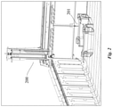
- FIG. 7 is an exemplary screenshot illustrating one embodiment of a scan of the router and object of FIG. 2 produced by the scanner of FIGS. 3A-B .
- FIG. 8 is an exemplary diagram illustrating an embodiment of a control system for controlling the system of FIGS. 3A-B .
- additive and/or subtractive manufacturing processes for scanning and locating structures for any post-processing of a 3D object can prove desirable and provide a basis for a wide range of applications, such as additive and subtractive manufacturing for vehicles and/or architectural structures.
- FIG. 1 shows an exemplary system 100 for additive manufacturing.
- the system 100 can print 3D articles via extrusion deposition (or material extrusion).
- a print head 120 is shown as including a nozzle configured to deposit one or more polymer layers onto a print bed 140 to form the 3D printed article.
- the print bed 140 can include a heated table and/or previously deposited layers.
- FIG. 1 shows additive manufacturing as being implemented by the system 100 using extrusion deposition
- any other systems or processes for implementing additive manufacturing can be used in the present disclosure.
- Exemplary processes for additive manufacturing can include binder jetting, directed energy deposition, material jetting, powder bed fusion, sheet lamination, vat photopolymerization, stereolithography, or a combination thereof.
- Additive manufacturing for making a 3D article on a large-scale can be referred to as large-scale additive manufacturing.
- a system (or technique) for large-scale additive manufacturing can be referred to as large-scale additive manufacturing system (or technique).
- Exemplary large-scale additive manufacturing systems include, for example, the Big Area Additive Manufacturing (BAAM) 100 ALPHA available from Cincinnati Incorporated located in Harrison, Ohio, or the Large Scale Additive Manufacturing (LSAM) machine available from Thermwood Corporation located in Dale, Ind.
- An exemplary system 100 that uses extrusion deposition for large-scale additive manufacturing includes the BAAM 100 ALPHA.
- the structures and methods as set forth in the present disclosure are applied to solve technical problems in large-scale additive and/or subtractive manufacturing, the structures and methods can be applied to any smaller-scale additive manufacturing, such as medium-scale and/or small-scale additive manufacturing, without limitation.
- an exemplary router 200 can post-process a printed object 201 .
- the exemplary router 200 can also operate on small-scale objects and/or other scaled objects without limitation.
- the printed object 201 shown in FIG. 2 can represent a large-scale additive manufacturing product produced by the additive manufacturing system 100 .
- shape geometry and physical constraints e.g., a small scanning space
- the systems and methods disclosed herein advantageously scan and locate parts in machine space independent of shape geometry.
- the printed object 201 may have some rounded corners, experience some drooping or deformation through the additive manufacturing process, and/or lack fine 3D geometry due to the material deposited, all of which can make the object 201 difficult to locate in machine space via reference points. Accordingly, in some embodiments, the systems and methods disclosed herein can scan and locate the printed object 201 without manual intervention.
- the scanner 300 can measure the three-dimensional shape of an object using projected light patterns and a camera system.
- structured light scanners can be used or laser scanning using red light-emitting diodes attached to the scanner can be used.
- a single scanner 300 is shown, those of ordinary skill in the art would understand that one or more scanners can be used.
- the scanner 300 can be maintained on a support system 350 , such as a tripod shown in FIG. 3A .
- the support system 350 can be stationary or placed on a mobile platform (not shown).
- the scanner 300 can include any combination of short-range scanners and/or long-range scanners.
- Short-range scanners can also include portable handheld scanners, such as shown in FIGS. 3A-3B .
- one or more long-range scanners are used for large objects. Long-range scanners advantageously reduce the need to move the scanner around the large part (e.g., around the milling machine) where there may not be a safe walkway for the operator to maneuver.
- a long-range scanner is discussed herein for exemplary purposes, those of ordinary skill in the art understand that one or more short-range scanners can be used. For example, a FaroArm from FARO in Lake Mary, Fla. can be used to scan the printed 3D object.
- FIG. 4 an exemplary method 4000 of scanning and locating the large object 201 using the scanner 300 on a mobile platform is shown.
- An operator begins the scanning routine, at 4010 .
- the scanner 300 begins a first scan, at 4020 .
- An exemplary scan 201 A of a portion of the object 201 is shown in FIG. 6A .
- the scanner 300 is selected with a scanning range to include at least one reference point of the object 201 in each scan.
- a machine coordinate system reference can be included in each scan.
- three tooling spheres such as tooling spheres 601 shown in FIG. 6A , can be attached to the router table.
- Three tooling spheres 601 are used in the preferred embodiment to advantageously lock in both the correct position and orientation of the machine/CAD origin.
- each scan includes at least one reference point of the object 201 , such as the tooling spheres discussed above.
- the reference points of each scan can be unique or common among scans. However, in yet another embodiment, not all scans need to include the reference points.
- an alignment reference (or locating feature) is determined, at 4040 .
- the alignment reference includes the reference point of each scan and/or a reference sphere.
- the alignment reference is a common reference system across one or more images that can be used to track location on an object for aligning the images. For example, adhesive reflective tabs and/or natural features of an object can be used to identify a specific location on an object across one or more images.
- the locating feature can include any common reference point surrounding the object 201 that can be determined, at 4040 .
- a corner of a table where the object 201 is placed can be used.
- each scan includes fiducial markers and at least a portion of the scanned object in the same scan.
- the scans can be aligned and merged, at 4050 , to create a complete 3D model of the object, such as shown in FIG. 6B .
- the scans are aligned to create a complete 3D model 201 B based on tooling spheres 601 .
- a best fit alignment can be used to align individual scans of the object 201 .
- a reference point then can be selected from one of the scans following the best fit alignment to ensure proper alignment to a fiducial marker.
- the scans are aligned and merged to a computer aided design (CAD) model (not shown) of the object 201 , at 4060 .
- FIG. 7 illustrates an exemplary complete scan of the router 200 and object 201 from FIG. 2 .
- the presence of scanned fiducial makers in the same file as the scanned object 201 enables a translation of physical machine space into a computer coordinate space.
- the system advantageously maps virtual coordinates, such as from the CAD file, to physical machine space locations, such as for use with CAM software.
- the alignment of the scans is based on a best fit.
- FIG. 5 the exemplary method 4000 scanning and locating a large object using one or more long-range scanners 300 that are each stationary is shown.
- each scanner 300 scans the object from their own position, at 4070 .
- each position provides a unique angle of the 3D object 201 .
- a reference point is determined, at 4040 .
- the reference point can be determined from a subset of the scans as at least a subset of the scans will include a reference point.
- each scan includes at least one reference point of the object 201 , such as the tooling spheres discussed above.
- adhesive reflective tabs and/or natural features of an object can be used to identify a specific location on an object across the plurality of scans.
- the scans can be aligned and merged, at 4050 , to create a complete 3D model of the object.
- a best fit alignment can be used to align individual scans of the object 201 .
- a reference point then can be selected from one of the scans following the best fit alignment to ensure proper alignment to a fiducial marker.
- the scans are aligned and merged to a computer aided design (CAD) model (not shown) of the object 201 , at 4060 .
- CAD computer aided design
- the presence of scanned fiducial makers in the same file as the scanned object 201 enables a translation of physical machine space into a computer coordinate space.
- the system advantageously maps virtual coordinates, such as from the CAD file, to physical machine space locations, such as for use with CAM software.
- the alignment of the scans is based on a best fit.
- the control system 500 can be configured for controlling the print head 120 (shown in FIG. 1 ), the router 200 (shown in FIG. 2 ), and/or the scanner 300 (shown in FIGS. 3A-B ).
- the control system 500 can include a processor 510 .
- the processor 510 can include one or more general-purpose microprocessors (for example, single or multi-core processors), application-specific integrated circuits, application-specific instruction-set processors, graphics processing units, physics processing units, digital signal processing units, coprocessors, network processing units, encryption processing units, and the like.
- the processor 510 can execute instructions for implementing the control system 500 and/or scanner 300 .
- the instructions include one or more additive and/or subtractive manufacturing software programs.
- the programs can operate to control the system 100 with multiple printing options, settings and techniques for implementing additive printing of large components.
- the programs can include a computer-aided design (CAD) program to generate a 3D computer model of the object. Additionally and/or alternatively, the 3D computer model can be imported from another computer system (not shown).
- the 3D computer model can be solid, surface or mesh file format in an industry standard.
- the programs can load the 3D computer model, create a print model and generate the machine code for controlling the system 100 to print, scan, locate, and/or post-process the object (e.g., via subtractive manufacturing).
- Exemplary programs can include LSAM Print 3D , available from Thermwood Corporation located in Dale, Ind. Additionally and/or alternatively, exemplary programs can include Unfolder Module Software, Bend Simulation Software, Laser Programming and/or Nesting Software available from Cincinnati Incorporated located in Harrison, Ohio.
- the control system 500 can include one or more additional hardware components as desired.
- Exemplary additional hardware components include, but are not limited to, a memory 520 (alternatively referred to herein as a non-transitory computer readable medium).
- Exemplary memory 520 can include, for example, random access memory (RAM), static RAM, dynamic RAM, read-only memory (ROM), programmable ROM, erasable programmable ROM, electrically erasable programmable ROM, flash memory, secure digital (SD) card, and/or the like.
- RAM random access memory
- ROM read-only memory
- programmable ROM programmable read-only memory
- erasable programmable ROM erasable programmable ROM
- electrically erasable programmable ROM flash memory
- SD secure digital
- control system 500 can include a communication module 530 .
- the communication module 530 can include any conventional hardware and software that operates to exchange data and/or instruction between the control system 500 and another computer system (not shown) using any wired and/or wireless communication methods.
- the control system 500 can receive computer-design data corresponding to the scans of the scanner 300 via the communication module 530 .
- Exemplary communication methods include, for example, radio, Wireless Fidelity (Wi-Fi), cellular, satellite, broadcasting, or a combination thereof.
- control system 500 can include a display device 540 .
- the display device 540 can include any device that operates to presenting programming instructions for operating the control system 500 and/or presenting data related to the print head 120 .
- control system 500 can include one or more input/output devices 550 (for example, buttons, a keyboard, keypad, trackball), as desired.
- the processor 510 , the memory 520 , the communication module 530 , the display device 540 , and/or the input/output device 550 can be configured to communicate, for example, using hardware connectors and buses and/or in a wireless manner.
Landscapes
- Engineering & Computer Science (AREA)
- Chemical & Material Sciences (AREA)
- Materials Engineering (AREA)
- Physics & Mathematics (AREA)
- Manufacturing & Machinery (AREA)
- Mechanical Engineering (AREA)
- Optics & Photonics (AREA)
- General Physics & Mathematics (AREA)
- Theoretical Computer Science (AREA)
- Automation & Control Theory (AREA)
- Human Computer Interaction (AREA)
- Geometry (AREA)
- Computer Vision & Pattern Recognition (AREA)
- Software Systems (AREA)
- Computer Graphics (AREA)
- Computer Hardware Design (AREA)
- Evolutionary Computation (AREA)
- General Engineering & Computer Science (AREA)
- Powder Metallurgy (AREA)
- Architecture (AREA)
Abstract
Description
Claims (19)
Priority Applications (1)
| Application Number | Priority Date | Filing Date | Title |
|---|---|---|---|
| US16/280,851 US11230062B2 (en) | 2018-02-20 | 2019-02-20 | Method and apparatus for additive manufacturing |
Applications Claiming Priority (2)
| Application Number | Priority Date | Filing Date | Title |
|---|---|---|---|
| US201862632560P | 2018-02-20 | 2018-02-20 | |
| US16/280,851 US11230062B2 (en) | 2018-02-20 | 2019-02-20 | Method and apparatus for additive manufacturing |
Publications (2)
| Publication Number | Publication Date |
|---|---|
| US20190255777A1 US20190255777A1 (en) | 2019-08-22 |
| US11230062B2 true US11230062B2 (en) | 2022-01-25 |
Family
ID=65686065
Family Applications (1)
| Application Number | Title | Priority Date | Filing Date |
|---|---|---|---|
| US16/280,851 Active US11230062B2 (en) | 2018-02-20 | 2019-02-20 | Method and apparatus for additive manufacturing |
Country Status (8)
| Country | Link |
|---|---|
| US (1) | US11230062B2 (en) |
| EP (1) | EP3755499A1 (en) |
| JP (1) | JP2021513924A (en) |
| KR (1) | KR20200120952A (en) |
| CN (1) | CN111757790A (en) |
| CA (1) | CA3091010A1 (en) |
| MX (1) | MX2020008679A (en) |
| WO (1) | WO2019164973A1 (en) |
Families Citing this family (6)
| Publication number | Priority date | Publication date | Assignee | Title |
|---|---|---|---|---|
| WO2017106965A1 (en) * | 2015-12-21 | 2017-06-29 | Ord Solutions Inc. | Method and apparatus for large format three-dimensional printing |
| IL312269B2 (en) * | 2020-07-27 | 2025-09-01 | Stratasys Ltd | Method and system for three-dimensional printing on fabric |
| CA3257133A1 (en) * | 2022-05-13 | 2023-11-16 | Firestorm Labs, Inc. | Mission-adaptable aerial vehicle and methods for in-field assembly and use |
| CN220721406U (en) * | 2022-06-09 | 2024-04-05 | 影石创新科技股份有限公司 | Unmanned aerial vehicle |
| CN115574754A (en) * | 2022-10-11 | 2023-01-06 | 杭州电子科技大学 | A Calibration Method of Articulated Coordinate Measuring Machine Based on Virtual Calibration Parts |
| US12486017B2 (en) | 2024-03-13 | 2025-12-02 | Firestorm Labs, Inc. | Additive manufactured integral fastening system for mission adaptable unmanned aerial vehicles |
Citations (23)
| Publication number | Priority date | Publication date | Assignee | Title |
|---|---|---|---|---|
| US5207371A (en) * | 1991-07-29 | 1993-05-04 | Prinz Fritz B | Method and apparatus for fabrication of three-dimensional metal articles by weld deposition |
| US20060173541A1 (en) | 2005-02-01 | 2006-08-03 | Mr. Timothy P. Friel | Ocular prosthesis and fabrication method of same |
| US20080181486A1 (en) * | 2007-01-26 | 2008-07-31 | Conversion Works, Inc. | Methodology for 3d scene reconstruction from 2d image sequences |
| US20090104585A1 (en) | 2007-10-19 | 2009-04-23 | Denis John Diangelo | Dental framework |
| US20090323121A1 (en) * | 2005-09-09 | 2009-12-31 | Robert Jan Valkenburg | A 3D Scene Scanner and a Position and Orientation System |
| US20100332196A1 (en) * | 2004-07-23 | 2010-12-30 | Rune Fisker | Adaptive 3d scanning |
| JP2012024920A (en) | 2003-04-28 | 2012-02-09 | 3D Scanners Ltd | Cmm arm with exoskeleton |
| US20120323345A1 (en) | 2010-03-04 | 2012-12-20 | Metrology Software Products Limited | Measurement method and apparatus |
| US20140035182A1 (en) * | 2012-07-31 | 2014-02-06 | Makerbot Industries, Llc | Augmented three-dimensional printing |
| US20140125658A1 (en) * | 2012-02-24 | 2014-05-08 | Matterport, Inc. | Capturing and aligning three-dimensional scenes |
| US20150061170A1 (en) | 2013-09-02 | 2015-03-05 | Thomas Engel | Method and arrangement for producing a workpiece by using additive manufacturing techniques |
| US20160335771A1 (en) * | 2015-05-15 | 2016-11-17 | Adobe Systems Incorporated | Incremental global non-rigid alignment of three-dimensional scans |
| US20160368220A1 (en) * | 2015-06-17 | 2016-12-22 | Xerox Corporation | System and method for evaluation of a three-dimensional (3d) object during formation of the object |
| US20160374431A1 (en) | 2012-07-18 | 2016-12-29 | Adam P. Tow | Systems and Methods for Manufacturing of Multi-Property Anatomically Customized Devices |
| US20170066193A1 (en) * | 2015-09-04 | 2017-03-09 | Electronics And Telecommunications Research Institute | 3d multifunctional device with 3d scanning function and 3d printing function and operation method thereof |
| US20170068756A1 (en) * | 2015-09-09 | 2017-03-09 | Xerox Corporation | System and method for internal structural defect analysis using three-dimensional sensor data |
| US9600929B1 (en) * | 2014-12-01 | 2017-03-21 | Ngrain (Canada) Corporation | System, computer-readable medium and method for 3D-differencing of 3D voxel models |
| US20170109888A1 (en) * | 2015-10-20 | 2017-04-20 | Hewlett-Packard Development Company, L.P. | Alignment of images of a three-dimensional object |
| US20170144242A1 (en) | 2015-11-24 | 2017-05-25 | Western Michigan University Research Foundation | 3d metal printing device and process |
| WO2017106965A1 (en) | 2015-12-21 | 2017-06-29 | Ord Solutions Inc. | Method and apparatus for large format three-dimensional printing |
| US20170287162A1 (en) * | 2014-08-29 | 2017-10-05 | Toyota Motor Europe | Method and system for scanning an object using an rgb-d sensor |
| EP3238865A1 (en) | 2016-04-29 | 2017-11-01 | Oxford Performance Materials, Inc. | Additive manufacturing process with in situ inspection of metallic objects |
| US20180130255A1 (en) * | 2016-11-04 | 2018-05-10 | Aquifi, Inc. | System and method for portable active 3d scanning |
Family Cites Families (11)
| Publication number | Priority date | Publication date | Assignee | Title |
|---|---|---|---|---|
| JP4130813B2 (en) * | 2004-05-26 | 2008-08-06 | 松下電工株式会社 | Three-dimensional shaped object manufacturing apparatus and light beam irradiation position and processing position correction method thereof |
| JP4957242B2 (en) * | 2006-12-28 | 2012-06-20 | ソニー株式会社 | Stereolithography equipment |
| EP2537642A1 (en) * | 2011-06-23 | 2012-12-26 | Raytheon BBN Technologies Corp. | Robot fabricator |
| US9003670B2 (en) * | 2012-03-08 | 2015-04-14 | United Technologies Corporation | System and method for measuring a workpiece relative to a common measurement coordinate system |
| CN203509463U (en) * | 2013-07-30 | 2014-04-02 | 华南理工大学 | Composite manufacturing device with conformal cooling channel injection mold |
| EP2887011B1 (en) * | 2013-12-20 | 2017-02-08 | Hexagon Technology Center GmbH | Coordinate measuring machine with high precision 3D printing functionality |
| US9789541B2 (en) * | 2014-03-07 | 2017-10-17 | Arcam Ab | Method for additive manufacturing of three-dimensional articles |
| CN106132668B (en) * | 2014-03-25 | 2018-05-15 | Dws有限公司 | Improved computer-implemented method for defining development points of support elements of objects manufactured by means of stereolithography processes |
| US20160297149A1 (en) * | 2015-04-08 | 2016-10-13 | Funfare, Llc | System, apparatus, and method for 3d scanning and printing |
| CN105844712B (en) * | 2016-03-16 | 2018-11-13 | 山东大学 | A kind of improved halftoning projection and model generating method towards 3D printing |
| CN106827514A (en) * | 2017-02-10 | 2017-06-13 | 上海联泰科技股份有限公司 | Layering builds image processing method, Method of printing and the 3D printing equipment of object |
-
2019
- 2019-02-20 WO PCT/US2019/018806 patent/WO2019164973A1/en not_active Ceased
- 2019-02-20 CA CA3091010A patent/CA3091010A1/en not_active Abandoned
- 2019-02-20 MX MX2020008679A patent/MX2020008679A/en unknown
- 2019-02-20 EP EP19709279.4A patent/EP3755499A1/en not_active Withdrawn
- 2019-02-20 KR KR1020207026790A patent/KR20200120952A/en not_active Ceased
- 2019-02-20 CN CN201980014512.4A patent/CN111757790A/en active Pending
- 2019-02-20 US US16/280,851 patent/US11230062B2/en active Active
- 2019-02-20 JP JP2020543491A patent/JP2021513924A/en active Pending
Patent Citations (24)
| Publication number | Priority date | Publication date | Assignee | Title |
|---|---|---|---|---|
| US5207371A (en) * | 1991-07-29 | 1993-05-04 | Prinz Fritz B | Method and apparatus for fabrication of three-dimensional metal articles by weld deposition |
| JP2012024920A (en) | 2003-04-28 | 2012-02-09 | 3D Scanners Ltd | Cmm arm with exoskeleton |
| US20100332196A1 (en) * | 2004-07-23 | 2010-12-30 | Rune Fisker | Adaptive 3d scanning |
| US20060173541A1 (en) | 2005-02-01 | 2006-08-03 | Mr. Timothy P. Friel | Ocular prosthesis and fabrication method of same |
| US20090323121A1 (en) * | 2005-09-09 | 2009-12-31 | Robert Jan Valkenburg | A 3D Scene Scanner and a Position and Orientation System |
| US20080181486A1 (en) * | 2007-01-26 | 2008-07-31 | Conversion Works, Inc. | Methodology for 3d scene reconstruction from 2d image sequences |
| US20090104585A1 (en) | 2007-10-19 | 2009-04-23 | Denis John Diangelo | Dental framework |
| US20120323345A1 (en) | 2010-03-04 | 2012-12-20 | Metrology Software Products Limited | Measurement method and apparatus |
| US20140125658A1 (en) * | 2012-02-24 | 2014-05-08 | Matterport, Inc. | Capturing and aligning three-dimensional scenes |
| US20140125767A1 (en) | 2012-02-24 | 2014-05-08 | Matterport, Inc. | Capturing and aligning three-dimensional scenes |
| US20160374431A1 (en) | 2012-07-18 | 2016-12-29 | Adam P. Tow | Systems and Methods for Manufacturing of Multi-Property Anatomically Customized Devices |
| US20140035182A1 (en) * | 2012-07-31 | 2014-02-06 | Makerbot Industries, Llc | Augmented three-dimensional printing |
| US20150061170A1 (en) | 2013-09-02 | 2015-03-05 | Thomas Engel | Method and arrangement for producing a workpiece by using additive manufacturing techniques |
| US20170287162A1 (en) * | 2014-08-29 | 2017-10-05 | Toyota Motor Europe | Method and system for scanning an object using an rgb-d sensor |
| US9600929B1 (en) * | 2014-12-01 | 2017-03-21 | Ngrain (Canada) Corporation | System, computer-readable medium and method for 3D-differencing of 3D voxel models |
| US20160335771A1 (en) * | 2015-05-15 | 2016-11-17 | Adobe Systems Incorporated | Incremental global non-rigid alignment of three-dimensional scans |
| US20160368220A1 (en) * | 2015-06-17 | 2016-12-22 | Xerox Corporation | System and method for evaluation of a three-dimensional (3d) object during formation of the object |
| US20170066193A1 (en) * | 2015-09-04 | 2017-03-09 | Electronics And Telecommunications Research Institute | 3d multifunctional device with 3d scanning function and 3d printing function and operation method thereof |
| US20170068756A1 (en) * | 2015-09-09 | 2017-03-09 | Xerox Corporation | System and method for internal structural defect analysis using three-dimensional sensor data |
| US20170109888A1 (en) * | 2015-10-20 | 2017-04-20 | Hewlett-Packard Development Company, L.P. | Alignment of images of a three-dimensional object |
| US20170144242A1 (en) | 2015-11-24 | 2017-05-25 | Western Michigan University Research Foundation | 3d metal printing device and process |
| WO2017106965A1 (en) | 2015-12-21 | 2017-06-29 | Ord Solutions Inc. | Method and apparatus for large format three-dimensional printing |
| EP3238865A1 (en) | 2016-04-29 | 2017-11-01 | Oxford Performance Materials, Inc. | Additive manufacturing process with in situ inspection of metallic objects |
| US20180130255A1 (en) * | 2016-11-04 | 2018-05-10 | Aquifi, Inc. | System and method for portable active 3d scanning |
Non-Patent Citations (5)
| Title |
|---|
| Chinese First Office Action, Application No. 201980014512.4 dated Jun. 25, 2021. |
| Examination Report, Application No. 3091010, dated Oct. 15, 2021. |
| Korean Office Action, Application No. 10-2020-7026790 dated Jun. 24, 2021. |
| Tyler Koslow, "Water Under World's First 3D Printed Pedestrian Bridge Completed in Madrid," https://all3dp.com/3d-printed-pedestrian-bridge/, Dec. 20, 2016 (Year: 2016). * |
| WO, International Report & Written Opinion, Application No. PCT/US2019/018806, dated Jul. 31, 2019. |
Also Published As
| Publication number | Publication date |
|---|---|
| KR20200120952A (en) | 2020-10-22 |
| CN111757790A (en) | 2020-10-09 |
| JP2021513924A (en) | 2021-06-03 |
| MX2020008679A (en) | 2020-09-25 |
| CA3091010A1 (en) | 2019-08-29 |
| US20190255777A1 (en) | 2019-08-22 |
| WO2019164973A1 (en) | 2019-08-29 |
| EP3755499A1 (en) | 2020-12-30 |
Similar Documents
| Publication | Publication Date | Title |
|---|---|---|
| US11230062B2 (en) | Method and apparatus for additive manufacturing | |
| US11048231B2 (en) | Beam tool pathing for 3D compound contours using machining path surfaces to maintain a single solid representation of objects | |
| US10369746B2 (en) | Three-dimensional data generation device, three-dimensional shaping device, and shaped object shaping method | |
| CN102473009B (en) | Automatic programming device and method | |
| CN104249221B (en) | The method of processing mould surface by using laser | |
| CN112692440B (en) | Laser marking method, system, device and storage medium | |
| Haipeng et al. | Generation and optimization of slice profile data in rapid prototyping and manufacturing | |
| Balabokhin et al. | Iso-scallop tool path building algorithm “based on tool performance metric” for generalized cutter and arbitrary milling zones in 3-axis CNC milling of free-form triangular meshed surfaces | |
| US20170165732A1 (en) | Metrology Assisted Part Forming System and Method | |
| EP4410518A1 (en) | Method and apparatus for determining 3d model printing position, a device, and a storage medium | |
| JP2001209417A (en) | Automatic programming system and recorded medium recording sheet metal graphic generation program | |
| CN110153582A (en) | Welding scheme generation method, device and welding system | |
| CN115222956A (en) | Multi-layer imported measurement system and its measurement method | |
| JP7508979B2 (en) | Data generation program and three-dimensional modeling system | |
| WO2014096412A2 (en) | Method for determining the workpiece location | |
| CN104755225A (en) | Automatic programming device and method | |
| CN120038441A (en) | Processing area adjusting method, device, equipment and storage medium | |
| JP6110692B2 (en) | Machining data creation system and method using original abutting tip and abutting position defining method | |
| Anamova et al. | Multiprocessing and correction algorithm of 3D-models for additive manufacturing | |
| WO2025023935A1 (en) | Mesh offsetting method | |
| US6681144B1 (en) | Process and system for working a workpiece through numerically controlled machine tools | |
| US20170115653A1 (en) | System and Method for Performing Operations of Numerical Control Machines | |
| JP7262655B2 (en) | DIMENSIONING DEVICE, DIMENSIONING METHOD AND PROGRAM | |
| JPH01155403A (en) | Method for generating processing path | |
| Cai et al. | Spiral tool path generation for high-speed milling of multi-connected surface based on quasi-conformal theory |
Legal Events
| Date | Code | Title | Description |
|---|---|---|---|
| FEPP | Fee payment procedure |
Free format text: ENTITY STATUS SET TO UNDISCOUNTED (ORIGINAL EVENT CODE: BIG.); ENTITY STATUS OF PATENT OWNER: SMALL ENTITY |
|
| FEPP | Fee payment procedure |
Free format text: ENTITY STATUS SET TO SMALL (ORIGINAL EVENT CODE: SMAL); ENTITY STATUS OF PATENT OWNER: SMALL ENTITY |
|
| AS | Assignment |
Owner name: LOCAL MOTORS IP, LLC, ARIZONA Free format text: ASSIGNMENT OF ASSIGNORS INTEREST;ASSIGNORS:FIECHTER, ALEXIS;NOVIKOV, TIMOFEI;BEDSOLE, ROBERT;AND OTHERS;SIGNING DATES FROM 20190326 TO 20190613;REEL/FRAME:049463/0909 |
|
| STPP | Information on status: patent application and granting procedure in general |
Free format text: NON FINAL ACTION MAILED |
|
| STPP | Information on status: patent application and granting procedure in general |
Free format text: FINAL REJECTION MAILED |
|
| STPP | Information on status: patent application and granting procedure in general |
Free format text: DOCKETED NEW CASE - READY FOR EXAMINATION |
|
| STPP | Information on status: patent application and granting procedure in general |
Free format text: NON FINAL ACTION MAILED |
|
| STPP | Information on status: patent application and granting procedure in general |
Free format text: RESPONSE TO NON-FINAL OFFICE ACTION ENTERED AND FORWARDED TO EXAMINER |
|
| STPP | Information on status: patent application and granting procedure in general |
Free format text: AWAITING TC RESP., ISSUE FEE NOT PAID |
|
| STPP | Information on status: patent application and granting procedure in general |
Free format text: NOTICE OF ALLOWANCE MAILED -- APPLICATION RECEIVED IN OFFICE OF PUBLICATIONS |
|
| STPP | Information on status: patent application and granting procedure in general |
Free format text: PUBLICATIONS -- ISSUE FEE PAYMENT RECEIVED |
|
| STPP | Information on status: patent application and granting procedure in general |
Free format text: PUBLICATIONS -- ISSUE FEE PAYMENT VERIFIED |
|
| STPP | Information on status: patent application and granting procedure in general |
Free format text: WITHDRAW FROM ISSUE AWAITING ACTION |
|
| STPP | Information on status: patent application and granting procedure in general |
Free format text: PUBLICATIONS -- ISSUE FEE PAYMENT VERIFIED |
|
| STCF | Information on status: patent grant |
Free format text: PATENTED CASE |
|
| AS | Assignment |
Owner name: CAPSTONE HOLDINGS, INC., FLORIDA Free format text: SECURITY INTEREST;ASSIGNOR:LOCAL MOTORS IP, LLC;REEL/FRAME:058793/0022 Effective date: 20220124 Owner name: FW LOCAL MOTORS, L.P., TEXAS Free format text: SECURITY INTEREST;ASSIGNOR:LOCAL MOTORS IP, LLC;REEL/FRAME:058793/0022 Effective date: 20220124 |
|
| AS | Assignment |
Owner name: RAPIDFLIGHT HOLDINGS, LLC, VIRGINIA Free format text: ASSIGNMENT OF ASSIGNORS INTEREST;ASSIGNOR:LMOTORS;REEL/FRAME:061661/0787 Effective date: 20220714 Owner name: LMOTORS, CALIFORNIA Free format text: ASSIGNMENT OF ASSIGNORS INTEREST;ASSIGNOR:LOCAL MOTORS IP, LLC;REEL/FRAME:061661/0683 Effective date: 20220125 |
|
| AS | Assignment |
Owner name: LMOTORS (ASSIGNMENT FOR THE BENEFIT OF CREDITORS), LLC, CALIFORNIA Free format text: CORRECTIVE ASSIGNMENT TO CORRECT THE ASSIGNEE'S NAME ON THE COVER SHEET PREVIOUSLY RECORDED AT REEL: 061661 FRAME: 0683. ASSIGNOR(S) HEREBY CONFIRMS THE ASSIGNMENT;ASSIGNOR:LOCAL MOTORS IP, LLC;REEL/FRAME:062101/0943 Effective date: 20220125 Owner name: RAPIDFLIGHT HOLDINGS, LLC, VIRGINIA Free format text: CORRECTIVE ASSIGNMENT TO CORRECT THE ASSIGNOR'S NAME ON THE COVER SHEET PREVIOUSLY RECORDED AT REEL: 061661 FRAME: 0787. ASSIGNOR(S) HEREBY CONFIRMS THE ASSIGNMENT;ASSIGNOR:LMOTORS (ASSIGNMENT FOR THE BENEFIT OF CREDITORS), LLC;REEL/FRAME:062101/0982 Effective date: 20220714 |
|
| FEPP | Fee payment procedure |
Free format text: ENTITY STATUS SET TO UNDISCOUNTED (ORIGINAL EVENT CODE: BIG.); ENTITY STATUS OF PATENT OWNER: LARGE ENTITY |
|
| MAFP | Maintenance fee payment |
Free format text: PAYMENT OF MAINTENANCE FEE, 4TH YEAR, LARGE ENTITY (ORIGINAL EVENT CODE: M1551); ENTITY STATUS OF PATENT OWNER: LARGE ENTITY Year of fee payment: 4 |
|
| AS | Assignment |
Owner name: LOCAL MOTORS IP, LLC, ARIZONA Free format text: RELEASE BY SECURED PARTY;ASSIGNORS:FW LOCAL MOTORS, L.P.;CAPSTONE HOLDINGS, INC.;REEL/FRAME:072284/0262 Effective date: 20220724 |
|
| AS | Assignment |
Owner name: AEVEX AEROSPACE, LLC, CALIFORNIA Free format text: ASSIGNMENT OF ASSIGNORS INTEREST;ASSIGNOR:RAPIDFLIGHT HOLDINGS, LLC;REEL/FRAME:073319/0845 Effective date: 20250825 |