JP2012024920A - Cmm arm with exoskeleton - Google Patents
Cmm arm with exoskeleton Download PDFInfo
- Publication number
- JP2012024920A JP2012024920A JP2011168620A JP2011168620A JP2012024920A JP 2012024920 A JP2012024920 A JP 2012024920A JP 2011168620 A JP2011168620 A JP 2011168620A JP 2011168620 A JP2011168620 A JP 2011168620A JP 2012024920 A JP2012024920 A JP 2012024920A
- Authority
- JP
- Japan
- Prior art keywords
- probe
- cmm arm
- reporting device
- robot
- movable
- Prior art date
- Legal status (The legal status is an assumption and is not a legal conclusion. Google has not performed a legal analysis and makes no representation as to the accuracy of the status listed.)
- Granted
Links
- 239000000523 sample Substances 0.000 claims abstract description 813
- 238000000034 method Methods 0.000 claims abstract description 283
- 230000005540 biological transmission Effects 0.000 claims abstract description 257
- 230000033001 locomotion Effects 0.000 claims description 91
- 210000000707 wrist Anatomy 0.000 claims description 8
- 230000000452 restraining effect Effects 0.000 claims description 3
- 238000005259 measurement Methods 0.000 abstract description 379
- 230000003287 optical effect Effects 0.000 abstract description 168
- 230000008569 process Effects 0.000 description 151
- 238000004519 manufacturing process Methods 0.000 description 83
- HOPMUCXYRNOABF-UHFFFAOYSA-N 1,2,3,4-tetrachloro-5-(2,3,5-trichlorophenyl)benzene Chemical compound ClC1=CC(Cl)=C(Cl)C(C=2C(=C(Cl)C(Cl)=C(Cl)C=2)Cl)=C1 HOPMUCXYRNOABF-UHFFFAOYSA-N 0.000 description 66
- 230000008901 benefit Effects 0.000 description 61
- 230000005484 gravity Effects 0.000 description 55
- 238000013461 design Methods 0.000 description 47
- 239000000463 material Substances 0.000 description 46
- PAYFWJAKKLILIT-UHFFFAOYSA-N 1,2,3,4,5-pentachloro-6-(2,3-dichlorophenyl)benzene Chemical compound ClC1=CC=CC(C=2C(=C(Cl)C(Cl)=C(Cl)C=2Cl)Cl)=C1Cl PAYFWJAKKLILIT-UHFFFAOYSA-N 0.000 description 40
- 238000005452 bending Methods 0.000 description 38
- 238000010586 diagram Methods 0.000 description 38
- 230000036961 partial effect Effects 0.000 description 38
- 230000006870 function Effects 0.000 description 33
- 238000012545 processing Methods 0.000 description 31
- 210000003128 head Anatomy 0.000 description 27
- 238000007689 inspection Methods 0.000 description 25
- 230000001133 acceleration Effects 0.000 description 24
- 239000013013 elastic material Substances 0.000 description 23
- 238000012856 packing Methods 0.000 description 20
- 230000002829 reductive effect Effects 0.000 description 20
- 230000009977 dual effect Effects 0.000 description 19
- 238000005516 engineering process Methods 0.000 description 17
- 238000004891 communication Methods 0.000 description 16
- 239000006260 foam Substances 0.000 description 16
- 230000008859 change Effects 0.000 description 15
- 230000000694 effects Effects 0.000 description 14
- 239000007787 solid Substances 0.000 description 14
- 230000009467 reduction Effects 0.000 description 12
- 230000003068 static effect Effects 0.000 description 12
- 230000001360 synchronised effect Effects 0.000 description 12
- 238000012935 Averaging Methods 0.000 description 11
- 241000350052 Daniellia ogea Species 0.000 description 11
- 238000004458 analytical method Methods 0.000 description 11
- 230000000875 corresponding effect Effects 0.000 description 11
- 229910052751 metal Inorganic materials 0.000 description 11
- 239000002184 metal Substances 0.000 description 11
- 230000006378 damage Effects 0.000 description 10
- 239000002783 friction material Substances 0.000 description 10
- 229920001971 elastomer Polymers 0.000 description 9
- 238000003754 machining Methods 0.000 description 9
- 238000002360 preparation method Methods 0.000 description 9
- 230000004044 response Effects 0.000 description 9
- 230000002441 reversible effect Effects 0.000 description 9
- 238000012546 transfer Methods 0.000 description 9
- 230000004913 activation Effects 0.000 description 8
- 238000009826 distribution Methods 0.000 description 8
- 230000007246 mechanism Effects 0.000 description 8
- 150000003071 polychlorinated biphenyls Chemical class 0.000 description 8
- 238000000926 separation method Methods 0.000 description 8
- 229910052782 aluminium Inorganic materials 0.000 description 7
- XAGFODPZIPBFFR-UHFFFAOYSA-N aluminium Chemical compound [Al] XAGFODPZIPBFFR-UHFFFAOYSA-N 0.000 description 7
- 230000007613 environmental effect Effects 0.000 description 7
- 238000009434 installation Methods 0.000 description 7
- 238000013507 mapping Methods 0.000 description 7
- 238000000691 measurement method Methods 0.000 description 7
- 230000008439 repair process Effects 0.000 description 7
- 230000035939 shock Effects 0.000 description 7
- 230000009471 action Effects 0.000 description 6
- 238000001514 detection method Methods 0.000 description 6
- 239000007789 gas Substances 0.000 description 6
- 238000003780 insertion Methods 0.000 description 6
- 230000037431 insertion Effects 0.000 description 6
- 210000002414 leg Anatomy 0.000 description 6
- 238000003801 milling Methods 0.000 description 6
- 238000012544 monitoring process Methods 0.000 description 6
- 238000012795 verification Methods 0.000 description 6
- 235000011960 Brassica ruvo Nutrition 0.000 description 5
- 239000011248 coating agent Substances 0.000 description 5
- 238000000576 coating method Methods 0.000 description 5
- 230000001276 controlling effect Effects 0.000 description 5
- 230000008878 coupling Effects 0.000 description 5
- 238000010168 coupling process Methods 0.000 description 5
- 238000005859 coupling reaction Methods 0.000 description 5
- 230000007423 decrease Effects 0.000 description 5
- 238000006073 displacement reaction Methods 0.000 description 5
- 238000002372 labelling Methods 0.000 description 5
- 239000004033 plastic Substances 0.000 description 5
- 229920003023 plastic Polymers 0.000 description 5
- 230000001681 protective effect Effects 0.000 description 5
- 238000012360 testing method Methods 0.000 description 5
- 238000012800 visualization Methods 0.000 description 5
- 229920000049 Carbon (fiber) Polymers 0.000 description 4
- 239000000853 adhesive Substances 0.000 description 4
- 230000001070 adhesive effect Effects 0.000 description 4
- 230000009286 beneficial effect Effects 0.000 description 4
- 238000004422 calculation algorithm Methods 0.000 description 4
- 239000004917 carbon fiber Substances 0.000 description 4
- 238000012937 correction Methods 0.000 description 4
- 210000004247 hand Anatomy 0.000 description 4
- VNWKTOKETHGBQD-UHFFFAOYSA-N methane Chemical compound C VNWKTOKETHGBQD-UHFFFAOYSA-N 0.000 description 4
- 230000001629 suppression Effects 0.000 description 4
- 238000011144 upstream manufacturing Methods 0.000 description 4
- 239000004593 Epoxy Substances 0.000 description 3
- 238000001816 cooling Methods 0.000 description 3
- 238000005520 cutting process Methods 0.000 description 3
- 230000005670 electromagnetic radiation Effects 0.000 description 3
- 230000001788 irregular Effects 0.000 description 3
- 239000003562 lightweight material Substances 0.000 description 3
- 238000009877 rendering Methods 0.000 description 3
- 238000004441 surface measurement Methods 0.000 description 3
- 230000009466 transformation Effects 0.000 description 3
- 230000000007 visual effect Effects 0.000 description 3
- 238000007794 visualization technique Methods 0.000 description 3
- 238000003466 welding Methods 0.000 description 3
- 239000006096 absorbing agent Substances 0.000 description 2
- 238000013459 approach Methods 0.000 description 2
- 238000003491 array Methods 0.000 description 2
- 230000000712 assembly Effects 0.000 description 2
- 238000000429 assembly Methods 0.000 description 2
- 230000015572 biosynthetic process Effects 0.000 description 2
- 230000000903 blocking effect Effects 0.000 description 2
- 239000002131 composite material Substances 0.000 description 2
- 230000008602 contraction Effects 0.000 description 2
- 230000003247 decreasing effect Effects 0.000 description 2
- 239000003344 environmental pollutant Substances 0.000 description 2
- 230000007274 generation of a signal involved in cell-cell signaling Effects 0.000 description 2
- 239000011521 glass Substances 0.000 description 2
- 230000006872 improvement Effects 0.000 description 2
- 238000002955 isolation Methods 0.000 description 2
- 229910052743 krypton Inorganic materials 0.000 description 2
- DNNSSWSSYDEUBZ-UHFFFAOYSA-N krypton atom Chemical compound [Kr] DNNSSWSSYDEUBZ-UHFFFAOYSA-N 0.000 description 2
- 229910001095 light aluminium alloy Inorganic materials 0.000 description 2
- 239000007788 liquid Substances 0.000 description 2
- 238000012423 maintenance Methods 0.000 description 2
- 230000013011 mating Effects 0.000 description 2
- 239000011159 matrix material Substances 0.000 description 2
- 230000000737 periodic effect Effects 0.000 description 2
- 229920001084 poly(chloroprene) Polymers 0.000 description 2
- 239000004810 polytetrafluoroethylene Substances 0.000 description 2
- 229920001343 polytetrafluoroethylene Polymers 0.000 description 2
- 230000007704 transition Effects 0.000 description 2
- 238000013519 translation Methods 0.000 description 2
- RXRLRYZUMSYVLS-UHFFFAOYSA-N 1,2,3,4-tetrachloro-5-(2,4,6-trichlorophenyl)benzene Chemical compound ClC1=CC(Cl)=CC(Cl)=C1C1=CC(Cl)=C(Cl)C(Cl)=C1Cl RXRLRYZUMSYVLS-UHFFFAOYSA-N 0.000 description 1
- MFRCZYUUKMFJQJ-UHFFFAOYSA-N 1,4-dioxane-2,5-dione;1,3-dioxan-2-one Chemical compound O=C1OCCCO1.O=C1COC(=O)CO1 MFRCZYUUKMFJQJ-UHFFFAOYSA-N 0.000 description 1
- 102100029272 5-demethoxyubiquinone hydroxylase, mitochondrial Human genes 0.000 description 1
- 101100024440 Globodera rostochiensis MSP-3 gene Proteins 0.000 description 1
- 101000770593 Homo sapiens 5-demethoxyubiquinone hydroxylase, mitochondrial Proteins 0.000 description 1
- 229910001374 Invar Inorganic materials 0.000 description 1
- 206010061258 Joint lock Diseases 0.000 description 1
- 125000002066 L-histidyl group Chemical group [H]N1C([H])=NC(C([H])([H])[C@](C(=O)[*])([H])N([H])[H])=C1[H] 0.000 description 1
- HCUVEUVIUAJXRB-UHFFFAOYSA-N OC1=C(C=C(CNC(CCCC=2SC=CC=2)=O)C=C1)OC Chemical compound OC1=C(C=C(CNC(CCCC=2SC=CC=2)=O)C=C1)OC HCUVEUVIUAJXRB-UHFFFAOYSA-N 0.000 description 1
- 239000004699 Ultra-high molecular weight polyethylene Substances 0.000 description 1
- 208000027418 Wounds and injury Diseases 0.000 description 1
- 238000009825 accumulation Methods 0.000 description 1
- 238000004026 adhesive bonding Methods 0.000 description 1
- 239000003570 air Substances 0.000 description 1
- 230000029777 axis specification Effects 0.000 description 1
- 238000004364 calculation method Methods 0.000 description 1
- 238000005266 casting Methods 0.000 description 1
- 230000015556 catabolic process Effects 0.000 description 1
- 239000000919 ceramic Substances 0.000 description 1
- 239000003795 chemical substances by application Substances 0.000 description 1
- 239000004927 clay Substances 0.000 description 1
- 238000004140 cleaning Methods 0.000 description 1
- 230000006835 compression Effects 0.000 description 1
- 238000007906 compression Methods 0.000 description 1
- 239000000470 constituent Substances 0.000 description 1
- 238000010276 construction Methods 0.000 description 1
- 239000000356 contaminant Substances 0.000 description 1
- 238000007796 conventional method Methods 0.000 description 1
- 230000002596 correlated effect Effects 0.000 description 1
- 230000007797 corrosion Effects 0.000 description 1
- 238000005260 corrosion Methods 0.000 description 1
- 238000013481 data capture Methods 0.000 description 1
- 238000005034 decoration Methods 0.000 description 1
- 238000006731 degradation reaction Methods 0.000 description 1
- 230000003111 delayed effect Effects 0.000 description 1
- 230000008021 deposition Effects 0.000 description 1
- 238000012938 design process Methods 0.000 description 1
- 238000011161 development Methods 0.000 description 1
- 230000018109 developmental process Effects 0.000 description 1
- 238000011143 downstream manufacturing Methods 0.000 description 1
- 238000005553 drilling Methods 0.000 description 1
- 239000003814 drug Substances 0.000 description 1
- 230000005611 electricity Effects 0.000 description 1
- 238000005265 energy consumption Methods 0.000 description 1
- 239000004744 fabric Substances 0.000 description 1
- 238000005242 forging Methods 0.000 description 1
- 238000007710 freezing Methods 0.000 description 1
- 230000008014 freezing Effects 0.000 description 1
- 239000000446 fuel Substances 0.000 description 1
- 238000007429 general method Methods 0.000 description 1
- 239000003365 glass fiber Substances 0.000 description 1
- 239000010438 granite Substances 0.000 description 1
- 238000000227 grinding Methods 0.000 description 1
- 238000003384 imaging method Methods 0.000 description 1
- 208000014674 injury Diseases 0.000 description 1
- 230000002452 interceptive effect Effects 0.000 description 1
- 238000005304 joining Methods 0.000 description 1
- 210000000629 knee joint Anatomy 0.000 description 1
- 238000011068 loading method Methods 0.000 description 1
- 230000007774 longterm Effects 0.000 description 1
- 238000012986 modification Methods 0.000 description 1
- 230000004048 modification Effects 0.000 description 1
- 238000000465 moulding Methods 0.000 description 1
- 238000011017 operating method Methods 0.000 description 1
- 238000005457 optimization Methods 0.000 description 1
- 230000008520 organization Effects 0.000 description 1
- 238000013021 overheating Methods 0.000 description 1
- 239000003973 paint Substances 0.000 description 1
- 238000010422 painting Methods 0.000 description 1
- 230000000149 penetrating effect Effects 0.000 description 1
- 230000035515 penetration Effects 0.000 description 1
- 239000002985 plastic film Substances 0.000 description 1
- 238000007781 pre-processing Methods 0.000 description 1
- 238000007639 printing Methods 0.000 description 1
- 238000004080 punching Methods 0.000 description 1
- 238000012797 qualification Methods 0.000 description 1
- 238000000275 quality assurance Methods 0.000 description 1
- 230000005855 radiation Effects 0.000 description 1
- 230000002285 radioactive effect Effects 0.000 description 1
- 238000011084 recovery Methods 0.000 description 1
- 230000000630 rising effect Effects 0.000 description 1
- 238000002432 robotic surgery Methods 0.000 description 1
- 238000005070 sampling Methods 0.000 description 1
- 230000009528 severe injury Effects 0.000 description 1
- 238000010008 shearing Methods 0.000 description 1
- 238000004088 simulation Methods 0.000 description 1
- 230000007480 spreading Effects 0.000 description 1
- 238000003892 spreading Methods 0.000 description 1
- 230000003746 surface roughness Effects 0.000 description 1
- 238000011477 surgical intervention Methods 0.000 description 1
- 230000002195 synergetic effect Effects 0.000 description 1
- 230000009897 systematic effect Effects 0.000 description 1
- 230000002123 temporal effect Effects 0.000 description 1
- 210000003813 thumb Anatomy 0.000 description 1
- 238000000844 transformation Methods 0.000 description 1
- 230000001960 triggered effect Effects 0.000 description 1
- 238000007514 turning Methods 0.000 description 1
- 229920000785 ultra high molecular weight polyethylene Polymers 0.000 description 1
- 238000002604 ultrasonography Methods 0.000 description 1
- 239000013598 vector Substances 0.000 description 1
- 238000009423 ventilation Methods 0.000 description 1
- 238000005303 weighing Methods 0.000 description 1
Images


Classifications
-
- B—PERFORMING OPERATIONS; TRANSPORTING
- B25—HAND TOOLS; PORTABLE POWER-DRIVEN TOOLS; MANIPULATORS
- B25J—MANIPULATORS; CHAMBERS PROVIDED WITH MANIPULATION DEVICES
- B25J13/00—Controls for manipulators
- B25J13/08—Controls for manipulators by means of sensing devices, e.g. viewing or touching devices
- B25J13/088—Controls for manipulators by means of sensing devices, e.g. viewing or touching devices with position, velocity or acceleration sensors
-
- G—PHYSICS
- G01—MEASURING; TESTING
- G01B—MEASURING LENGTH, THICKNESS OR SIMILAR LINEAR DIMENSIONS; MEASURING ANGLES; MEASURING AREAS; MEASURING IRREGULARITIES OF SURFACES OR CONTOURS
- G01B11/00—Measuring arrangements characterised by the use of optical techniques
- G01B11/02—Measuring arrangements characterised by the use of optical techniques for measuring length, width or thickness
- G01B11/03—Measuring arrangements characterised by the use of optical techniques for measuring length, width or thickness by measuring coordinates of points
-
- G—PHYSICS
- G01—MEASURING; TESTING
- G01B—MEASURING LENGTH, THICKNESS OR SIMILAR LINEAR DIMENSIONS; MEASURING ANGLES; MEASURING AREAS; MEASURING IRREGULARITIES OF SURFACES OR CONTOURS
- G01B5/00—Measuring arrangements characterised by the use of mechanical techniques
- G01B5/004—Measuring arrangements characterised by the use of mechanical techniques for measuring coordinates of points
- G01B5/008—Measuring arrangements characterised by the use of mechanical techniques for measuring coordinates of points using coordinate measuring machines
-
- G—PHYSICS
- G05—CONTROLLING; REGULATING
- G05B—CONTROL OR REGULATING SYSTEMS IN GENERAL; FUNCTIONAL ELEMENTS OF SUCH SYSTEMS; MONITORING OR TESTING ARRANGEMENTS FOR SUCH SYSTEMS OR ELEMENTS
- G05B2219/00—Program-control systems
- G05B2219/30—Nc systems
- G05B2219/37—Measurements
- G05B2219/37274—Strain gauge
-
- G—PHYSICS
- G05—CONTROLLING; REGULATING
- G05B—CONTROL OR REGULATING SYSTEMS IN GENERAL; FUNCTIONAL ELEMENTS OF SUCH SYSTEMS; MONITORING OR TESTING ARRANGEMENTS FOR SUCH SYSTEMS OR ELEMENTS
- G05B2219/00—Program-control systems
- G05B2219/30—Nc systems
- G05B2219/40—Robotics, robotics mapping to robotics vision
- G05B2219/40305—Exoskeleton, human robot interaction, extenders
Landscapes
- Engineering & Computer Science (AREA)
- Physics & Mathematics (AREA)
- General Physics & Mathematics (AREA)
- Human Computer Interaction (AREA)
- Robotics (AREA)
- Mechanical Engineering (AREA)
- Manipulator (AREA)
- A Measuring Device Byusing Mechanical Method (AREA)
- Length Measuring Devices With Unspecified Measuring Means (AREA)
- Testing Or Calibration Of Command Recording Devices (AREA)
- Machine Tool Sensing Apparatuses (AREA)
Abstract
Description
[発明の分野]
本発明は、高精度な測定及び動作を行うための外骨格を有するCMMアームに関する装置及び方法に関する。
[Field of the Invention]
The present invention relates to an apparatus and a method related to a CMM arm having an exoskeleton for performing highly accurate measurement and operation.
[発明の背景]
既存の自動測定法
中型から大型のサイズの物体を自動測定するには、0.05mm(+/−2シグマ)、通常は0.025mm(+/−2シグマ)以上の測定機精度が必要である。「シグマ」とは、1標準偏差を意味する。自動測定は現在、主に2つの方法、(i)3つ以上の軸を有する大型で高価な従来のコンピュータ数値制御座標測定機(CNC CMM)、(ii)自動車生産ラインの終端にある専用セルに通常は位置付けられる、静的光学プローブの剛性構造、で行われている。従来のCMMでは、光学プローブが静止物体の周りを極めて制御された方法で移動して、正確なデータを生成する。第2の場合では、光学プローブ及び物体の両方が静止しており、位置決めが較正されることにより正確なデータが可能になる。従来のCMMのほとんどは、移動ブリッジ又は水平アームの構造であり、Zeiss(ドイツ)、Hexagon Brown&Sharpe(スウェーデン)、及びLK(英国)を含む企業がこれらを生産している。従来のCMMに取り付けられる機械式タッチプローブは、Renishaw(英国)を含む企業により供給されている。従来のCMMに取り付けられる光学プローブは、Metris(ベルギー)を含む企業により供給されている。Renishaw Autojoint等の自動プローブマウントは、高精度まで再現可能であり、自動プローブ交換のためのプローブラックとともに供給される。静的光学プローブの剛構造は、Perceptron(米国)により供給されている。従来のCMM及び静的光学プローブの両方が、以下の欠点を有する。すなわち、従来のCMM及び静的光学プローブは、生産ラインにおいて、通常は測定のためだけに用いられて生産作業には用いられないセル空間を使い切り、通常はラインの終端に設置され、下流のプロセスにデータを供給することができず、高価であり、投資回収を考えても正当化し難い。さらに、光学プローブの剛構造は、生産ラインにおいて急速に変化するモデルに対応する柔軟性がない。既存の高精度測定システムの欠点により、今日では、従来のプロセスよりも高速、高性能、且つ安価であるが高精度位置決めを必要とするロボットを用いる効率的な生産プロセスを、生産ラインで利用することはできない。
[Background of the invention]
Existing automatic measurement method Automatic measurement of medium to large size objects requires a measuring machine accuracy of 0.05mm (+/- 2 sigma), usually 0.025mm (+/- 2 sigma) or higher. is there. “Sigma” means one standard deviation. Automatic measurement currently has two main methods: (i) a large and expensive conventional computer numerical control coordinate measuring machine (CNC CMM) with more than two axes; (ii) a dedicated cell at the end of the automobile production line It is usually done with a rigid structure of a static optical probe, which is positioned. In a conventional CMM, an optical probe moves around a stationary object in a highly controlled manner to generate accurate data. In the second case, both the optical probe and the object are stationary and the positioning is calibrated to allow accurate data. Most conventional CMMs are moving bridge or horizontal arm structures, which are produced by companies including Zeiss (Germany), Hexagon Brown & Sharpe (Sweden), and LK (UK). Mechanical touch probes attached to conventional CMMs are supplied by companies including Renishaw (UK). Optical probes attached to conventional CMMs are supplied by companies including Metris (Belgium). Automatic probe mounts such as Renishaw Autojoin are reproducible to high precision and are supplied with a probe rack for automatic probe replacement. The rigid structure of the static optical probe is supplied by Perceptron (USA). Both conventional CMM and static optical probes have the following disadvantages. In other words, conventional CMMs and static optical probes use up cell space that is normally used only for measurement and not for production work in the production line, and is usually installed at the end of the line, downstream processes. Data cannot be supplied to the network, it is expensive, and it is difficult to justify it even considering investment recovery. Furthermore, the rigid structure of the optical probe is not flexible to accommodate rapidly changing models in the production line. Due to the shortcomings of existing high-precision measurement systems, today, the production line uses an efficient production process that uses robots that are faster, perform better, and cheaper than conventional processes but require high-precision positioning. It is not possible.
ロボット自動測定
1960年代以来、各企業により、短いサイクルタイム及び再現性を必要とする用途のために、重いロボットアームが開発されてきた。しかしながら、主に温度、磨耗、及び振動の問題から、これらのロボットアームの精度は低い。ロボットは、自動測定用のプローブを担持するために用いられてきた。ロボットアームは、特に自動車産業において、ほとんどの自動測定の厳しい要件を満たすのに十分な精度を有さない。ロボットアームの高い再現性により、「準静的な」測定は自動車産業が少なからず取り入れる解決手段となった。「準静的な」測定では、プローブは或る位置から次の位置へ移動し、静止しているかゆっくりと移動している場合にのみデータを取る。測定は、接触プローブ又は非接触プローブのいずれでも行うことができる。ロボットアームの測定プローブは、通常は10mm/秒〜200mm/秒(但し、それよりも速くても遅くてもよい)の速度で移動しながら、物体の表面から3次元データを取るが、精度は低い。ロボットアームを生産する企業には、Fanuc(日本)及びKuka(ドイツ)が含まれる。Perceptron及びLMI-Diffracto(米国)は、ロボットアーム及び光学プローブを用いる解決手段を提供している。3D Scanners及びKukaは、フランクフルトでのユーロモールド(Euromold)2001見本市において、リアルタイム光学検査による解決手段を示したが、その精度は0.5〜1mmのオーダであった。標準的な産業ロボットの熱成長は、リーチ1メートル当たり1℃の温度上昇につき約10ミクロンであり、500ミクロンを超える誤差は、生産ライン状態で記録され得る。LMI-Diffractoは、Kukaにより供給されている、それぞれが光学プローブを担持する標準的な産業ロボットを4つ備える自動生産ライン設備を有し、このロボットは熱成長が補償されるため、生産ライン状態の熱誤差が100ミクロン未満に減る可能性がある。Perceptronに譲渡されたGreerによる米国特許第6,078,846号では、ロボットの熱成長の補償は、光学プローブにより固定アーチファクトを測定することにより実行される。光学プローブは、ロボットが移動間で静止している間に測定を行う。誤差マッピングがロボットの精度を高めた。Krypton(オランダ)製又はNorthern Digital(カナダ)製のもの等の写真測量システムを用いて測定を行いながら、計画的な移動のプログラムの間ロボットを揺動させる(dancing)ことを含む、いくつかの手法がある。続いて、測定値を用いて誤差マップが作成される。荷重の誤差補償は、サーボにより用いられる電力を測定して、アームにかかる荷重を自動的に計算することにより、すでに行われている。複数のタイプの誤差補償を用いた場合でも、自動車生産ラインで多く見られるタイプ及びリーチのロボットでは0.2mm(+/−2シグマ)の精度しか得られなかった。走査中にプローブと物体との間で相対移動が行われる走査プローブを担持するロボットアームに関する問題は、システムが有用となるのに十分な精度を有さないことである。
Automatic Robot Measurement Since the 1960s, companies have developed heavy robot arms for applications that require short cycle times and repeatability. However, the accuracy of these robot arms is low, mainly due to temperature, wear, and vibration problems. Robots have been used to carry probes for automatic measurement. Robot arms do not have sufficient accuracy to meet the stringent requirements of most automatic measurements, especially in the automotive industry. Due to the high reproducibility of the robotic arm, “quasi-static” measurements have become a solution that is more or less adopted by the automotive industry. In a “quasi-static” measurement, the probe moves from one position to the next and takes data only when it is stationary or moving slowly. The measurement can be performed with either a contact probe or a non-contact probe. The measurement probe of the robot arm usually takes 3D data from the surface of the object while moving at a speed of 10 mm / sec to 200 mm / sec (however, it may be faster or slower). Low. Companies that produce robot arms include Fanuc (Japan) and Kuka (Germany). Perceptron and LMI-Diffracto (USA) provide solutions using robotic arms and optical probes. 3D Scanners and Kuka showed solutions by real-time optical inspection at the Euromold 2001 trade show in Frankfurt, but the accuracy was on the order of 0.5-1 mm. Typical industrial robot thermal growth is about 10 microns for a 1 ° C. temperature rise per meter reach, and errors over 500 microns can be recorded in production line conditions. LMI-Diffracto has an automatic production line facility supplied by Kuka with four standard industrial robots each carrying an optical probe, which is compensated for thermal growth so that the production line condition Can be reduced to less than 100 microns. In US Pat. No. 6,078,846 to Greer, assigned to Perceptron, compensation for robot thermal growth is performed by measuring fixed artifacts with an optical probe. The optical probe performs measurements while the robot is stationary between movements. Error mapping increases the accuracy of the robot. Several measures, including dancing the robot during a planned movement program while taking measurements using a photogrammetry system such as those from Krypton (Netherlands) or Northern Digital (Canada) There is a technique. Subsequently, an error map is created using the measured values. Load error compensation has already been performed by measuring the power used by the servo and automatically calculating the load on the arm. Even when multiple types of error compensation were used, only 0.2 mm (+/− 2 sigma) accuracy was obtained with the type and reach robots often found in automobile production lines. A problem with a robotic arm carrying a scanning probe in which relative movement between the probe and object occurs during scanning is that the system is not accurate enough to be useful.
追跡
Long他による米国特許第6,166,811号では、プローブに取り付けられた写真測量標的を写真測量システムによりリアルタイムで追跡する、物体の走査の精度を高めるための写真測量システムが開示されている。この方法には多くの欠点がある。第1に、プローブと写真測量用カメラとの間に、複数の明瞭な視線が維持される必要がある。実際には、写真測量用カメラからプローブ上の写真測量標的までの視線は、プログラムされたロボットの移動及び/又は物体の走査に必要なプローブの向きのプログラムされた変化により、遮られる場合が多い。これにより、システムの適用性は大きな制約を受けるため、システムは多くの用途で役に立たなくなってしまう。第2に、環境照明状態をほぼ理想的な状態に保たなければならず、そうしなければ写真測量システムの精度が低下するか、又はシステムの機能が停止する。実際には、これは設定が困難であり、その場所での他の照明要件と相容れない場合が多い。第3に、写真測量システムは、この用途で十分な精度を提供するのに必要な分解能及び速度の両方を有さない場合が多い。第4に、写真測量用カメラ及びロボットは、互いに対してしっかりと取り付けられなければならない。これには、所望の精度を得るために寸法の大きい剛構造が必要となる場合が多い。写真測定技術をロボット測定システムに組み込むことに関する主な問題は、得られるシステムが有用となるほど十分に小型且つ堅牢ではないことである。
Pursuit
US Pat. No. 6,166,811 by Long et al. Discloses a photogrammetry system for improving the accuracy of object scanning by tracking a photogrammetry target attached to a probe in real time by a photogrammetry system. This method has many drawbacks. First, it is necessary to maintain a plurality of clear lines of sight between the probe and the photogrammetry camera. In practice, the line of sight from the photogrammetric camera to the photogrammetric target on the probe is often obstructed by programmed changes in probe orientation required for programmed robot movement and / or object scanning. . This limits the applicability of the system, making the system useless for many applications. Second, the ambient lighting conditions must be kept approximately ideal, otherwise the photogrammetry system will be less accurate or the system will stop functioning. In practice, this is difficult to set up and is often incompatible with other lighting requirements at that location. Third, photogrammetry systems often do not have both the resolution and speed necessary to provide sufficient accuracy for this application. Fourth, the photogrammetry camera and robot must be securely attached to each other. This often requires a rigid structure with large dimensions to obtain the desired accuracy. The main problem with incorporating photographic measurement technology into robotic measurement systems is that the resulting system is not small and robust enough to be useful.
Leica Geosystemsは、6自由度のレーザトラッカLTD800を供給している。これは、1秒間に最高1000回の測定で、1つの視線で35mの範囲にわたって位置及び向きを測定することができる。その精度は、ゆっくりと移動する標的の場合は50ミクロンのオーダである。その価格は、130,000USドルを超える。ロボット測定に関するその制限の多くは、写真測量の制限と同様である。レーザトラッカ技術をロボット測定システムに組み込むことに関する主な問題は、高価であり、追跡されるプローブの向きが制限され、得られるシステムが有用となるほど十分に小型且つ堅牢ではないことである。 Leica Geosystems supplies the 6 degree of freedom laser tracker LTD800. This can measure the position and orientation over a range of 35 m with a single line of sight, with up to 1000 measurements per second. Its accuracy is on the order of 50 microns for a slowly moving target. Its price is over US $ 130,000. Many of the restrictions on robotic measurements are similar to those of photogrammetry. The main problem with incorporating laser tracker technology into a robotic measurement system is that it is expensive, the orientation of the probe being tracked is limited, and the resulting system is not small and robust enough to be useful.
ロボットコントローラ及びプログラミング
ロボットアームのコントローラは、当業者には十分に理解されている。標準的な参考文献は、Richard P Paulによる「Robot Manipulators, Mathematics Programming and Control」である。Adept Technologies(米国)は、6軸ロボットコントローラを8,500USドルの価格から供給している。動きのシーケンスをオフラインで生成し、続いてそれを後で実行するためにロボットコントローラに伝達するロボットのプログラミングに利用可能な製品は数多くあるが、一例はTenomatix(米国)のEmWorkplaceである。HA Shlatter AG(スイス)に譲渡されたRichterによる特許出願GB2036376Aでは、ロボットに取り付けられたデバイスをユーザが保持してロボットを手動でガイドすることにより、プログラミングが行われ、デバイスはユーザが意図したロボットの方向を検知する歪みゲージを備える。
Robot Controller and Programming Robot arm controllers are well understood by those skilled in the art. The standard reference is “Robot Manipulators, Mathematics Programming and Control” by Richard P Paul. Adept Technologies (USA) supplies a 6-axis robot controller starting at a price of US $ 8,500. There are many products available for robot programming that generate a sequence of movements offline and subsequently communicate them to a robot controller for later execution, one example being EmWorkplace from Tenomaxix (USA). In patent application GB2036376A by Richter, assigned to HA Shlatter AG (Switzerland), programming is performed by manually holding the device while the device is attached to the robot, and the device is the robot intended by the user. A strain gauge that detects the direction of
手動CMMアーム
1970年代以来、各企業は手動操作可能なCMMアームを製造しており、これは、主に手動CMMアームのリーチに応じて0.025mm(+/−2シグマ)〜0.005mm(+/−2シグマ)の測定精度を、接触プローブを用いて近年達成している。手動CMMアームの精度は、さらなる開発によりさらに高まると予測される。これらの手動CMMアームはすでに、多くの測定要件を満たすのに十分な精度を有しており、測定市場における成長部門である。手動CMMアームは、アクセスが困難な領域に到達することができる柔軟性を有する。手動CMMアームは、多くの用途で満足できる精度を有するが、自動化はされず、特に半熟練の作業者が必要であるため操作費用が高く、人間の作業者では人的ミスが起こりやすい。手動CMMアームを生産する企業としては、Cimcore(米国)、Faro Technologies(米国)、Romer(フランス)、Zett Mess Technik(ドイツ)、及びOGP(英国)が挙げられる。例として、Eatonによる米国特許第3,994,798号、Faro Technologiesに譲渡されたRaabによる米国特許第5,402,582号、Eatonによる米国特許第5,829,148号、及びFaro Technologiesに譲渡されたRaabによる米国特許第6,366,831号は、手動CMMアームに関する背景情報を開示している。手動CMMアームの継手に軸受を設けることは既知であり、Faro Technologiesに譲渡されたRaabによる米国特許出願第2002/0087233号は、軸受に関する背景情報を開示している。手動CMMアームの設計は、通常、継手1の中心からプローブ先端までのリーチが約2メートルに制限されるが、これは、それよりも長いとアームを用いるのに2人の作業者が必要だからである。手動CMMアームは、長くなるほど精度が低下する。概して、モジュール式の手動CMMアーム設計で、他の全ての要素が同じである場合、精度はやはり長さに反比例する。Raabによる米国特許第6,366,831号では、現場において、手動CMMアームは通常、ロボットアームの10倍以上の絶対位置精度を有すると開示されている。ロボットにおいて継手の位置ずれを含む不正確を引き起こす要因のいくつかが、米国特許第6,366,831号で言及されている。Faro Technologies及びRomerにより製造されるもの等の手動CMMアームは、概して、1人の人間が両手で操作する。作業者の手はそれぞれ、手で把持される手動CMMアームの部分に、異なる6自由度の作用を与える。用途によっては、片手しか必要としない熟練作業者もいる。手動CMMアームは、作業者がループを完結させる、閉ループ式で制御される機構である。このような制御は熟練を要する作業であり、作業者は、2つの手のみを用いて、重力の影響下で様々な異なる空間レイアウトで6つ又は7つのアーム自由軸を制御する必要がある。作業者が手動CMMアームの操作を誤り、手動CMMアームの一部又は全部が、衝突するか又は作業者が押さえるまで重力により加速することはよくある。データの取り込み中に、作業者が手動CMMアームに可変の、場合によっては過剰な力及びトルクを加えることにより、手動CMMアームが出力する測定データの精度が低下することもある。
Manual CMM Arms Since the 1970s, companies have been manufacturing manually operable CMM arms, mainly depending on the reach of manual CMM arms, from 0.025mm (+/- 2 sigma) to 0.005mm ( Measurement accuracy of (+/- 2 sigma) has recently been achieved using a contact probe. The accuracy of the Manual CMM Arm is expected to increase further with further development. These manual CMM arms already have sufficient accuracy to meet many measurement requirements and are a growing sector in the measurement market. The Manual CMM Arm has the flexibility to reach areas that are difficult to access. Manual CMM Arms have satisfactory accuracy for many applications, but are not automated, are particularly expensive because they require semi-skilled workers, and human workers are prone to human error. Companies that produce manual CMM arms include Cimcore (USA), Faro Technologies (USA), Romer (France), Zett Mess Technik (Germany), and OGP (UK). Examples include U.S. Pat. No. 3,994,798 to Eaton, U.S. Pat. No. 5,402,582 to Rab assigned to Faro Technologies, U.S. Pat. No. 5,829,148 to Eaton, and assigned to Faro Technologies. Raab, US Pat. No. 6,366,831, discloses background information on manual CMM arms. It is known to provide a bearing on the joint of a manual CMM arm, and US Patent Application No. 2002/0087233 by Raab assigned to Faro Technologies discloses background information on bearings. Manual CMM arm designs are typically limited to a reach of about 2 meters from the center of fitting 1 to the probe tip, because longer than that requires two workers to use the arm. It is. The accuracy of the manual CMM arm decreases with increasing length. In general, in a modular manual CMM arm design, if all other elements are the same, the accuracy is also inversely proportional to the length. US Pat. No. 6,366,831 by Raab discloses that in the field, a manual CMM arm typically has an absolute positional accuracy of more than 10 times that of a robot arm. Some of the factors that cause inaccuracies including joint misalignment in robots are mentioned in US Pat. No. 6,366,831. Manual CMM arms, such as those manufactured by Faro Technologies and Romer, are generally operated by one person with both hands. Each of the operator's hands exerts six different degrees of freedom on the portion of the Manual CMM Arm that is gripped by the hand. Some skilled workers require only one hand, depending on the application. The manual CMM arm is a closed-loop controlled mechanism that allows the operator to complete the loop. Such control is a skillful task and requires the operator to control six or seven arm free axes in a variety of different spatial layouts under the influence of gravity using only two hands. Often, an operator misoperates the Manual CMM Arm and some or all of the Manual CMM Arm is accelerated by gravity until it collides or is pressed by the operator. During data capture, the operator may apply variable and possibly excessive force and torque to the Manual CMM Arm, reducing the accuracy of the measurement data output by the Manual CMM Arm.
補償デバイス及び保持デバイス
手動CMMアームは通常、上腕に持ち上げ力を与えて釣り合いを取る傾向があるトルクを上腕に与える、第2の継手に内蔵される補償デバイスを有する。手動CMMアームの補償デバイスは、Raab他による米国特許第6,298,569号、Raab他による米国特許第6,253,458号、及びRaab他による米国特許出願第2003/0167647号に開示されており、これらはすべてFaro Technologiesに譲渡されている。これは、アームが軽く作業者にとって持ち上げやすくなっているため、使用時の疲労が少ないことを意味する。これは、手動CMMアームを介して伝達されるトルクがより大きいことも意味し、要件として、手動CMMアームは、必要な精度を得るためにこのような補償デバイスを有さない場合よりも重く設計されなければならない。ロボットの消費電力並びにモータのパワー、サイズ、及び重量を減らすために、ロボットを補償することが標準的な慣行である。第2003/0167647号では、垂下した向きで用いる場合、加工ばね補償デバイスを取り外し、反転させ、再び配置して、アームを補償することができるが、この手順は、工場内で行われなければならないため、ユーザにとって不都合である。手動CMMアームの中には、アームの1つ又は複数の軸を任意の空間的向きにロックする保持デバイスを有するものがあり、このような保持デバイスは、測定セットごとにアームを下に置く必要をなくす。Cimcore(米国)製の3000シリーズ手動CMMアームでは、軸2(第1の直交ヒンジ軸)にある補償デバイスに摺動ペグ固定具(sliding peg fixing)が取り付けられており、ペグが穴に滑り込むと、軸2が通る補償デバイスがロックされる。複数の軸上の空気ブレーキは、Zett Mess Technik GmbHに譲渡されたNietzによるPCT/EP01/01570に開示されており、Zett MessのAMPG−P手動CMMアーム製品の軸1〜4に設けられている。空気ブレーキは、無線遠隔制御スイッチにより解除することができ、空気ブレーキはディスクに作用する。空気ブレーキ及びディスクは、手動CMMアームに直接取り付けられ、手動CMMアームの重量を増し、手動CMMアームの軸受にモーメントを伝えることにより、その精度及び有用性を低下させる。
Compensation Device and Holding Device Manual CMM Arms typically have a compensation device built into the second joint that provides the upper arm with a torque that tends to counterbalance by lifting the upper arm. Manual CMM Arm compensation devices are disclosed in US Pat. No. 6,298,569 by Raab et al., US Pat. No. 6,253,458 by Raab et al. And US Patent Application No. 2003/0167647 by Raab et al. All of which have been transferred to Faro Technologies. This means that the arm is light and easy to lift for the operator, so there is less fatigue during use. This also means that the torque transmitted through the Manual CMM Arm is greater, and as a requirement, the Manual CMM Arm is designed to be heavier than without such a compensation device to obtain the required accuracy. It must be. It is standard practice to compensate for robots to reduce robot power consumption and motor power, size, and weight. In 2003/0167647, when used in a suspended orientation, the processing spring compensation device can be removed, flipped and repositioned to compensate the arm, but this procedure must be performed in the factory This is inconvenient for the user. Some manual CMM arms have a holding device that locks one or more axes of the arm in any spatial orientation, and such holding devices require the arm to be down for each measurement set. Is lost. In the 3000 Series Manual CMM Arm made by Cimcore (USA), a sliding peg fixing is attached to the compensation device on axis 2 (first orthogonal hinge axis) and when the peg slides into the hole , The compensation device through which
手動CMMアームの光学プローブ
手動CMMアームの光学プローブは、本発明の発明者であるCramptonにより、WO9705449を含むいくつかの特許出願に開示された。手動CMMアームの光学プローブは、特に、3D Scanners、Romer、Faro Technologies、Perceptron、Steinbichler(ドイツ)、Pulstec(日本)、及びKreon(フランス)により提供又は開発されている。光学プローブは、概して、手動CMMアームの側部にずらして取り付けられるか、又は手動CMMアームのプローブ端に取り付けられる。大別すると3つのタイプの光学プローブ、すなわちポイント光学プローブ、ライン光学プローブ、及びエリア光学プローブがある。今のところ、ポイント光学プローブ、ライン光学プローブ、及びエリア光学プローブに関する精度を測定すべき方法を規定する測定精度標準はない。市場は、実用的な方法で精度を確かめて光学プローブのタイプ間を比較することを可能にする標準試験を行うことができないという状況にある。光学プローブは、主にその測定範囲が短いことから、高精度になってきている。概して、光学プローブは、20〜40mmのオーダの測定範囲にわたって測定データを収集する。これは、手動CMMアームの端から離れている場合が多い。最も優れた手動CMMアームを最も優れた光学プローブと組み合わせた場合の精度は、すでに0.050mm(+/−2シグマ)よりも高精度であり、測定範囲が短ければ0.010mm(+/−2シグマ)よりも、さらには0.002mm(+/−2シグマ)よりも高精度になり得る。
Manual CMM Arm Optical Probes Manual CMM Arm optical probes have been disclosed in several patent applications including WO 9705449 by the inventor of the present invention, Crampton. Optical probes for manual CMM arms are provided or developed by 3D Scanners, Romer, Faro Technologies, Perceptron, Steinbichler (Germany), Pulstec (Japan), and Kreon (France), among others. The optical probe is generally mounted off the side of the manual CMM arm or attached to the probe end of the manual CMM arm. Broadly speaking, there are three types of optical probes: point optical probes, line optical probes, and area optical probes. At present, there is no measurement accuracy standard that defines how accuracy should be measured for point optical probes, line optical probes, and area optical probes. The market is in a situation where it is not possible to carry out standard tests that make it possible to compare accuracy between optical probe types in a practical way. Optical probes have become highly accurate mainly due to their short measurement range. In general, an optical probe collects measurement data over a measurement range on the order of 20-40 mm. This is often away from the end of the manual CMM arm. The accuracy when combining the best manual CMM arm with the best optical probe is already higher than 0.050 mm (+/- 2 sigma), and 0.010 mm (+/-) if the measurement range is short 2 sigma) and even higher than 0.002 mm (+/- 2 sigma).
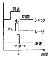
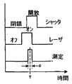
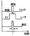
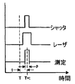
手動CMMアームの光学プローブの同期化及び補間
手動CMMアーム及び光学プローブを備えるシステムでは、それぞれからの測定値が合成されて、出力測定データが与えられる。本発明の発明者であるCramptonによるWO9705449に開示されているように、手動CMMアーム及び光学プローブを備えるシステムの測定精度は、手動CMMアームからの測定と光学プローブからの測定のタイミングを同期させることにより高まる。代替的に、WO9705449にさらに開示されているように、手動CMMアーム及び光学プローブを備えるシステムの測定精度は、手動CMMアームからの各測定値にタイムスタンプし、光学プローブからの各測定値にタイムスタンプし、その後、2つの測定値セットを補間して組み合わせた測定値セットを提供するプロセスを用いることにより高まる。しかしながら、場合によっては、システムに混乱が起こり、いずれかのデバイスからの1つ又は複数の測定値が失われる。この状況では、後半の補間プロセスが複雑になり得る。
Manual CMM Arm Optical Probe Synchronization and Interpolation In systems with a manual CMM arm and optical probe, measurements from each are combined to provide output measurement data. As disclosed in WO 9705449 by Crampton, the inventor of the present invention, the measurement accuracy of a system comprising a manual CMM arm and an optical probe synchronizes the timing of the measurement from the manual CMM arm and the measurement from the optical probe. Will increase. Alternatively, as further disclosed in WO 9705449, the measurement accuracy of a system comprising a manual CMM arm and an optical probe is time stamped on each measurement from the manual CMM arm and timed on each measurement from the optical probe. It is enhanced by using a process that stamps and then interpolates the two measurement sets to provide a combined measurement set. However, in some cases, the system is confused and one or more measurements from any device are lost. In this situation, the later interpolation process can be complicated.
ロボット及び手動CMMアームの較正及び位置合わせ
Shellによる米国特許第5,687,293号に開示されているように、ロボットは、基準球体と、ロボットに取り付けられている先端が球状のプローブとを用いて、種々のロボット空間レイアウトで先端が球状のプローブを基準球体に複数回接触させることにより、較正することができる。6軸ロボットの実施形態の39パラメータキネマティックモデルが開示されている。ロボットに対する光学プローブの位置合わせは、De Smetによる米国特許第6,321,137号(B1)に開示されている。手動CMMアームを手動で較正する方法は、Faro Technologiesに譲渡されたRaabによる米国特許第5,402,582号に開示されている。手動CMMアームは、出荷前に製造業者により較正される。Faro Technologiesを含むいくつかの供給業者は、手動CMMアームの較正は同じまま、ユーザがプローブを交換するたびに簡単にプローブ較正を行うことができるようにしている。OGP UKは、極性(Polar)手動CMMアームを供給し、ユーザが簡単な手順で極性アーム及びプローブを合わせて完全に較正することができるようにしており、この手順は、アームを様々な空間レイアウトで動かしながら、極性アームの球状プローブが置かれる複数の円錐を有する基準アーチファクトを用いて行われる。これらの6軸極性アームには39パラメータ運動力学(kinematic)モデルが用いられる。手動CMMアームの完全且つ高精度な手動較正は、通常は500の別個のポイントが数時間かかるプロセスで記録される、骨の折れるプロセスである。各ポイントで人的ミスが起こりやすい。異なる作業者が異なる場所で手動CMMアームを保持し、異なるグリップを介して異なるトルクを付与し、異なるパターンの荷重及び曲げモーメントをアームに加えるため、異なる撓み及び端部傾斜が生じる。手動で較正される手動CMMアームは、各作業者の持ち方及び使用の仕方に応じて異なった機能をすることになる。各空間的向きでどのような持ち方をしても、再現可能なパターンの荷重及び曲げモーメント下にあるような手動CMMアームが必要である。異なる作業者が用いる場合に生じる荷重及び曲げモーメントが同じパターンであるような、手動CMMアームを手動で較正する方法が必要である。その較正の再現性及び精度を高め、特に現在の手動プロセスで実用的又は費用効果的であるよりも多くのポイントを記録することを可能にする、手動CMMアームを自動で較正する方法が必要である。手動CMMアームに対する光学プローブの位置合わせ(較正又は適格化(qualification)としても知られる)は、本発明の発明者であるCramptonによるWO9705449号に開示されている。
Calibration and alignment of robots and manual CMM arms
As disclosed in US Pat. No. 5,687,293 by Shell, the robot uses a reference sphere and a probe with a spherical tip attached to the robot, and the tip is arranged in various robot space layouts. Calibration can be done by bringing the spherical probe into contact with the reference sphere multiple times. A 39-parameter kinematic model of a 6-axis robot embodiment is disclosed. The alignment of the optical probe with respect to the robot is disclosed in US Pat. No. 6,321,137 (B1) by De Smet. A method for manually calibrating a manual CMM arm is disclosed in US Pat. No. 5,402,582 by Raab assigned to Faro Technologies. The Manual CMM Arm is calibrated by the manufacturer before shipping. Several suppliers, including Faro Technologies, allow manual probe calibration to be easily performed each time the user changes the probe while the calibration of the manual CMM arm remains the same. OGP UK supplies Polar manual CMM arms, allowing users to fully calibrate polar arms and probes together in a simple procedure, which allows the arm to be placed in various spatial layouts. This is done using a reference artifact having a plurality of cones on which the spherical probe of the polar arm is placed. A 39-parameter kinematic model is used for these 6-axis polar arms. Full and accurate manual calibration of a Manual CMM Arm is a laborious process, typically 500 separate points are recorded in a process that takes several hours. Human error is likely to occur at each point. Different workers hold the Manual CMM Arm at different locations, apply different torques through different grips, and apply different patterns of loads and bending moments to the arms, resulting in different flexures and end tilts. A manual CMM arm that is manually calibrated will function differently depending on how each operator holds and uses. Whatever way you hold in each spatial orientation, you need a manual CMM arm that is under a reproducible pattern of loads and bending moments. There is a need for a method of manually calibrating a manual CMM arm such that the loads and bending moments that occur when used by different workers are in the same pattern. There is a need for a method of automatically calibrating a manual CMM Arm that increases the reproducibility and accuracy of its calibration and allows more points to be recorded than is practical or cost effective, especially with current manual processes. is there. The alignment of the optical probe to the manual CMM arm (also known as calibration or qualification) is disclosed in WO 9705449 by Crampton, the inventor of the present invention.
ロボット及び測定デバイスの取り付け
Tounai他による米国特許第5,392,384に開示されているように、6軸関節測定デバイスの先端は、ロボットを較正するためにロボットの先端に取り付けられる。Faro Technologiesに譲渡されたRaabによる米国特許第6,535,794号に開示されているように、6軸関節測定デバイスの先端は、誤差マップを生成するためにロボットの先端に取り付けられる。Bieg他による米国特許第6,519,860号に開示されているように、3軸関節測定デバイスの先端は、ロボット又は機械の空間性能を測定するためにロボット又は機械の先端に取り付けられる。これらの開示はいずれも、物体を測定するためには用いられていない。WahrburgによるWO98/27887に開示されているように、外科ロボット及び多継手センサアームがベースに取り付けられる。多継手センサアームを手動で用いて患者の測定が行われ、これらの測定に基づいてロボットプログラムが生成され、ロボットが外科的介入を実行する。この開示では、測定は自動化されていない。従来技術の2つのアイテムが、曲げによる撓み及び/又は熱膨張を受けやすいロボットアームの端点の位置及び/又は向きを測定するデバイスを開示している。Flemmingによる米国特許第4,119,212号に開示されているように、両端にしっかりと取り付けられた平面ゴニオメータを有する単純な膝継手を用いて、移動セグメントの端の場所が監視される。このデバイスは、平面での動作に制限され、面外の曲げは測定されない。したがって、このデバイスは、3D空間での位置及び向きを測定することができない。Slocumによる米国特許第4,606,696号に開示されているように、ロボットアームの端の位置及び向きを測定するデバイスは、回転軸受及びリニア軸受により繋がれる多数の測定リンクと、回転角及び直線移動を測定する測定デバイスとを備える。測定リンクは、ロボットアームの両端点にピン留めされるだけでなく、少なくとも1つの中間ヒンジ継手でロボットアームにしっかりとピン留めされる。この手法には、6軸ロボットに対して12個の高精度な回転及び直線測定デバイスが必要である。12個の測定デバイスからの誤差が積み重なるため、この手法を6軸ロボットの高精度な3D測定デバイスに発展させることが果たしてできるかどうかは疑わしくなる。付加的な回転及び直線測定デバイスが必要なく、それらに関連する誤差が積み重ならない、より単純でより堅牢なシステムが必要である。米国特許第4,119,212号及び米国特許第4,606,696号はいずれも、ロボットアームの各端に測定デバイスをしっかりと取り付けることを必要とする。プローブ端へのしっかりとした取り付けは、ロボットアームの端の位置を正確に測定するのに必須である。ロボットアームを用いてCMMアームを位置決めする場合、プローブ端へのしっかりとした取り付けは必要なく、望ましくもない。米国特許第4,119,212号及び米国特許第4,606,696号はいずれも、デバイスにおいて較正情報を用いる手段を提供していない。これらはいずれも、デバイスを座標測定機として用いることを提案していない。較正情報を用いなければ、デバイスが現在の用途で必要とされるほど高精度になり得るかどうかは疑わしい。
Installation of robot and measuring device
As disclosed in US Pat. No. 5,392,384 to Tounai et al., The tip of the six-axis articulation measurement device is attached to the tip of the robot to calibrate the robot. As disclosed in US Pat. No. 6,535,794 by Raab assigned to Faro Technologies, the tip of the six-axis articulation device is attached to the tip of the robot to generate an error map. As disclosed in US Pat. No. 6,519,860 to Bieg et al., The tip of the three-axis articulating device is attached to the tip of the robot or machine to measure the spatial performance of the robot or machine. None of these disclosures are used to measure objects. A surgical robot and a multi-joint sensor arm are attached to the base as disclosed in WO 98/27887 by Wahrburg. Patient measurements are made manually using the multi-joint sensor arm, a robot program is generated based on these measurements, and the robot performs the surgical intervention. In this disclosure, the measurement is not automated. Two items of the prior art disclose devices that measure the position and / or orientation of the end points of robotic arms that are susceptible to bending deflection and / or thermal expansion. As disclosed in U.S. Pat. No. 4,119,212 by Flemming, the location of the end of the moving segment is monitored using a simple knee joint having a planar goniometer securely attached to both ends. This device is limited to operation in a plane and no out-of-plane bending is measured. Therefore, this device cannot measure the position and orientation in 3D space. As disclosed in U.S. Pat. No. 4,606,696 to Slocum, a device for measuring the position and orientation of the end of a robot arm comprises a number of measurement links connected by rotary and linear bearings, a rotation angle and A measuring device for measuring linear movement. The measurement link is not only pinned to the end points of the robot arm, but is also firmly pinned to the robot arm with at least one intermediate hinge joint. This technique requires twelve highly accurate rotation and linear measurement devices for a 6-axis robot. Since the errors from the twelve measuring devices accumulate, it is questionable whether this technique can be developed into a highly accurate 3D measuring device for a 6-axis robot. There is a need for a simpler and more robust system that does not require additional rotational and linear measurement devices and does not accumulate the errors associated with them. U.S. Pat. No. 4,119,212 and U.S. Pat. No. 4,606,696 both require a measurement device to be securely attached to each end of the robot arm. Secure attachment to the probe end is essential to accurately measure the position of the end of the robot arm. When positioning a CMM arm using a robotic arm, a secure attachment to the probe end is not necessary or desirable. Neither US Pat. No. 4,119,212 and US Pat. No. 4,606,696 provide a means for using calibration information in the device. None of these suggests using the device as a coordinate measuring machine. Without calibration information, it is questionable whether the device can be as accurate as needed in current applications.
他の背景
GoochによるPCT/GB01/01590に開示されているように、ロボットのプローブ端に光学プローブ及び工具の両方が取り付けられるロボットが示され、このロボットを用いて、光学プローブでの測定及び工具での作業を選択的に行うことができる。しかしながら、測定精度を得るために、上述の欠点の全てを有する光学追跡システムが用いられる。GoochによるPCT/GB01/01590にさらに開示されているように、ロボットは、移動式であり、例えばレール上に取り付けられて、測定中の大きな物体の周りにアクセスできるようにする。このさらなる開示も、光学追跡の欠点を有する。Faroのアームを利用する手動罫書き(marking out)システム及びKuka製の産業ロボットを利用するロボット罫書きシステムが、GoochによるPCT/GB01/03865に開示されている。これら2つのシステムは、高精度であるか又は自動化されているが、両方を兼ね備えてはいない。手動CMMアームに取り付けられた非接触センサによる、回転テーブル上の物体の手動走査は、本発明の発明者であるCramptonにより、WO9705449に開示されている。大きな物体のフライス削り(milling)は、標準的な5軸又は6軸の産業ロボットにより実行されているが、得られる物体は、標準的な産業ロボットの精度が限られているため高精度ではなく、通常は、種々の向きからの切削が行われる手仕上げが必要である。大きな物体のフライス削りは、Mecof spa(イタリア)により製造されるもの等の大型の5軸マシニングセンターと、Zeiss製及びLK Tool製のもの等の大型の5軸水平アームCMMとで、正確に行われることが普通である。加工され得る物体の種類は、直交座標型機械(Cartesian machine type)により制限され、例えば、水平アームはコーナの周りを曲がることができない。Delcam(英国)は、5軸及び6軸の産業ロボット用のフライス削りプログラムを生成することが可能な、PowerShapeと呼ばれるソフトウェアを提供している。
Other background
As disclosed in PCT / GB01 / 01590 by Gooch, a robot is shown in which both an optical probe and a tool are attached to the probe end of the robot, using this robot to measure with an optical probe and work with a tool Can be selectively performed. However, to obtain measurement accuracy, an optical tracking system having all of the above-mentioned drawbacks is used. As further disclosed in PCT / GB01 / 01590 by Gooch, the robot is mobile, for example mounted on a rail, allowing access around a large object being measured. This further disclosure also has the disadvantage of optical tracking. A manual marking out system using Faro's arm and a robot marking system using an industrial robot made by Kuka are disclosed in PCT / GB01 / 03865 by Gooch. These two systems are either highly accurate or automated, but not both. Manual scanning of an object on a rotary table by a non-contact sensor attached to a manual CMM arm is disclosed in WO 9705449 by Crampton, the inventor of the present invention. Large object milling is performed by standard 5-axis or 6-axis industrial robots, but the resulting object is not highly accurate due to the limited accuracy of standard industrial robots. Usually, hand finishing is required in which cutting is performed from various directions. Milling of large objects is performed accurately with large 5-axis machining centers such as those manufactured by Mecof spa (Italy) and large 5-axis horizontal arms CMM such as those made by Zeiss and LK Tool. It is normal. The types of objects that can be machined are limited by Cartesian machine types, for example, horizontal arms cannot bend around corners. Delcam (UK) offers software called PowerShape that can generate milling programs for 5-axis and 6-axis industrial robots.
精度の必要性
ユーザは、自身の手動CMMアームからさらに高い精度を得ることを望んでいる。作業者が手動CMMアームに過大な応力を加えること、種々のハンドグリップ位置からアームに加わるモーメントにばらつきがあること、及び組み込まれている釣合い重りが軸受にモーメントを与えることから、手動CMMアームにおいてかなりの誤差が生じる。CMMアームに対する荷重が持ち方の影響を受けず、かなり精度が高い、より再現性が高い手動CMMアームが必要である。人的ミスをなくすように自動化された、より精度が高い較正プロセスがさらに必要である。
Need for accuracy Users want to get even higher accuracy from their manual CMM Arm. In manual CMM arms, the operator applies excessive stress to the manual CMM arm, there are variations in the moment applied to the arm from various handgrip positions, and the built-in counterweight gives moment to the bearing. A considerable error occurs. There is a need for a manual CMM arm that is highly reproducible and highly reproducible, with the load on the CMM arm being unaffected by how it is held. There is a further need for a more accurate calibration process that is automated to eliminate human error.
自動化の必要性
光学プローブを有する手動CMMアームは、通常は連続で長時間用いられる。この時間の大半の間、作業者は、自身から離れた場所にある、多くの場合は不便な場所にある手動CMMアームを保持する。離れて支持される重量は、長い手動CMMアームの場合は数キログラムであり得る。これは重労働であり、多くの作業者を、特に体が小さい人ほど疲労させる。作業者の疲労は一般的な問題であり、これは、病気、機能喪失、又は傷害に至る可能性がある。手動CMMアームを用いて行われる作業の大半は、一度しか光学検査を必要としない独特な構成部品に対するものである。多くの場合、検査される表面は、直接アクセス可能ではなく、アームを操作できるように作業者が上る一時的なガントリが必要である。走査中にプローブと物体との間で相対移動が行われる、走査プローブを担持する手動CMMアームに関する問題は、これらが十分な精度を有していても、システムは自動的に動作することができないため、システムの使用に疲労が伴い、作業者のミス又は手動CMMアームへの過大な応力により、不正確なデータが出力され得ることである。
The need for automation Manual CMM arms with optical probes are usually used continuously for extended periods of time. During most of this time, the operator holds a manual CMM arm that is remote from him, often in an inconvenient location. The remotely supported weight can be several kilograms for a long manual CMM arm. This is hard work and fatigues many workers, especially those with a small body. Worker fatigue is a common problem, which can lead to illness, loss of function, or injury. Most of the work done with the Manual CMM Arm is for unique components that only require optical inspection once. In many cases, the surface to be inspected is not directly accessible, but requires a temporary gantry that allows the operator to climb up to operate the arm. The problem with manual CMM arms carrying scanning probes where relative movement occurs between the probe and the object during scanning is that the system cannot operate automatically even if they have sufficient accuracy Thus, the use of the system is fatigued and incorrect data can be output due to operator error or excessive stress on the manual CMM arm.
アクセス性の必要性
測定すべき物体の形状と、可動部材上のプローブへのそのアクセス性は、用途ごとに異なる。物体の形状のより大きな範囲にアクセスするのに十分な柔軟性を有するCMMほど、有用性が高い。実際には、硬質セグメントにより隔てられた一連の好ましくは6つ又は7つの継手を備える関節アームCMMは、直交軸構成のCMMよりも柔軟性が高いことが、一般的に分かっている。技術の現状では、直交軸構成の自動CMMは、自動関節ロボットアームよりも精度が数オーダ高いことも、一般的に分かっている。直交軸構成の自動CMMは、自動関節アームロボットよりも組み立てライン等の製造環境への配置に適していないことも、一般的に分かっている。問題は、関節式であり十分な精度を有する自動CMM機が利用可能ではないことである。
Necessity of accessibility The shape of the object to be measured and its accessibility to the probe on the movable member vary from application to application. A CMM that is flexible enough to access a larger range of object shapes is more useful. In practice, it has generally been found that articulated arm CMMs with a series of preferably six or seven joints separated by rigid segments are more flexible than orthogonal configuration CMMs. In the current state of the art, it is also generally known that an automatic CMM with orthogonal axis configuration is several orders of magnitude more accurate than an automatic articulated robot arm. It has also been generally found that an orthogonal CMM automatic CMM is less suitable for placement in a manufacturing environment such as an assembly line than an automatic articulated arm robot. The problem is that automatic CMM machines that are articulated and have sufficient accuracy are not available.
可搬性の必要性
1990年代半ばに十分な精度を有するようになって以来、約5,000程度の可搬式手動CMMアームが購入されていることが示すように、可搬式手動CMMアームに対する需要は大きい。それに対応して、可搬式自動CMMアームも必要とされているが、現在は存在していない。
The need for portability As shown by the fact that around 5,000 portable manual CMM arms have been purchased since becoming sufficiently accurate in the mid-1990s, the demand for portable manual CMM arms is large. Correspondingly, a portable automatic CMM arm is also required, but currently does not exist.
堅牢性の必要性
手動CMMアームは、より高精度になるとともに堅牢性が低下してきている。手動CMMアームの既存の設計は、使用及び輸送の際に衝撃、モーメント、及び酷使(abuse:手荒な扱い)を受けやすい、精密測定システムを有する。輸送ケースの既存の設計は単純であるため、手動CMMアームは、特に衝撃により損傷を受ける。堅牢な可搬式手動CMMアームと、輸送時の衝撃から手動CMMアームに加わる力及びモーメントを最小限に抑える輸送ケースとが必要である。
The need for robustness Manual CMM arms have become more accurate and less robust. Existing designs of Manual CMM Arms have precision measurement systems that are susceptible to shock, moments, and abuse during use and transportation. Since the existing design of the transport case is simple, the manual CMM arm is particularly damaged by impact. There is a need for a robust, portable manual CMM arm and a transport case that minimizes the forces and moments applied to the manual CMM arm from impacts during transport.
[発明の概要]
従来技術では、Flemmingが、平面内でのみ使用可能であり面外の曲げを考慮に入れていない、測定アームが取り付けられたロボットアームを開示している。Slocumは、3D空間内で動作するロボットアームのための測定デバイスを開示している。これは、6軸ロボットに対して12個の回転及び直線測定デバイスを必要とし、複雑であり、製造費用が高く、誤差の積み重ねにより精度が制限される。
[Summary of Invention]
In the prior art, Flemming discloses a robot arm fitted with a measuring arm that can only be used in a plane and does not take into account out-of-plane bending. Slocum discloses a measuring device for a robotic arm that operates in 3D space. This requires 12 rotational and linear measuring devices for a 6-axis robot, is complex, expensive to manufacture, and accuracy is limited by error stackup.
したがって、本発明の目的の1つは、3D空間で動作し、且つ軸ごとに1つの測定デバイスしか必要としない、すなわち、6軸CMMアームには6つの角度エンコーダ、7軸CMMアームには7つの角度エンコーダしか必要としない、外骨格及び伝達手段を有するCMMアームを提供することである。これにより、Slocumのデバイスよりも著しく堅牢且つ高精度であり、Flemmingのデバイスでの制限である3D空間で動作することができる、外骨格を有するCMMアームが得られる。手動動作及び自動の両方の実施形態を有する、外骨格を有するCMMアームを提供することが、本発明のさらなる目的である。別の目的は、データを収集できる外骨格を有するCMMアームを提供することである。さらに別の目的は、作業を行うことができる外骨格を有するCMMアームを提供することである。
Thus, one of the objectives of the present invention operates in 3D space and requires only one measurement device per axis,
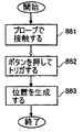
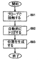
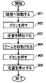
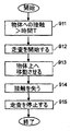
本発明の第1の実施形態では、可搬式ロボットCMMアームが、物体の測定を実行することができるように伝達手段を介して内部CMMアームを支持及び操作する、自動外骨格を備える。ロボットCMMアーム及び内部CMMアームは、ベースにしっかりと取り付けられる。外骨格及び内部CMMアームは、同じ数の軸と、ほぼ同じ継手軸の向き及び継手中心とを有する。ロボットCMMアームは、6つ又は7つの軸を有することが好ましい。外骨格が内部CMMアームの駆動及び支持の両方を行うように、外骨格と内部CMMアームとの間には伝達手段がある。伝達手段は、非硬質であり、内部CMMアームのプローブ端は、外骨格のプローブ端に対してわずかに移動することができる。この第1の実施形態は、ロボットアームのプローブ端と測定デバイスのプローブ端とをしっかりと取り付ける必要があるSlocum及びFlemmingのデバイスとは基本的に異なる。内部CMMアームのプローブ端には、少なくとも1つのプローブが取り付けられる。内部CMMアームからの位置及びプローブからの測定値が組み合わせられ、その組み合わせの曖昧性による精度不良を回避するために、新規の体系的に変化する同期ラベル及び同期方法が提案される。ロボットCMMアームのベースには、制御ボックスが組み込まれる。スリップリングが、軸方向の軸(axial axes)上での無限回転を可能にする。ロボットCMMアームは通常、20〜30kgの重量があり、可搬式であるため、測定される物体の方へ移動させることができる。物体のデータを測定するためにロボットCMMアームを位置決めする方法を提供することが、この第1の実施形態のさらなる目的である。このロボットCMMアームの発明は、新規の構造と、いずれのロボット、手動CMMアーム、又は従来のCMMも可能ではない新規の能力を有する。 In a first embodiment of the invention, the portable Robot CMM Arm comprises an automatic exoskeleton that supports and manipulates the Internal CMM Arm via a transmission means so that object measurements can be performed. The Robot CMM Arm and the Internal CMM Arm are securely attached to the base. The exoskeleton and the internal CMM arms have the same number of axes and approximately the same joint axis orientation and joint center. The Robot CMM Arm preferably has 6 or 7 axes. There is a transmission means between the exoskeleton and the internal CMM arm so that the exoskeleton both drives and supports the internal CMM arm. The transmission means is non-rigid and the probe end of the internal CMM arm can move slightly relative to the probe end of the exoskeleton. This first embodiment is fundamentally different from the Slocum and Flemming devices that require a secure attachment of the probe end of the robot arm and the probe end of the measurement device. At least one probe is attached to the probe end of the internal CMM arm. In order to combine the position from the internal CMM arm and the measurements from the probe and avoid inaccuracies due to the ambiguity of the combination, a new systematically changing synchronization label and synchronization method is proposed. A control box is incorporated in the base of the Robot CMM Arm. A slip ring allows infinite rotation on the axial axes. The Robot CMM Arm usually weighs 20-30 kg and is portable so it can be moved towards the object to be measured. It is a further object of this first embodiment to provide a method for positioning a Robot CMM Arm to measure object data. This Robot CMM Arm invention has a new structure and new capabilities that are not possible with any robot, manual CMM arm, or conventional CMM.
本発明の第2の実施形態では、産業ロボットCMMアームが、内部CMMアームを囲む外骨格を備える。産業ロボットCMMアームには、フライス削り等の作業を行うための工具を取り付けることができる。外骨格及び内部CMMアームは、プローブ端でしっかりと取り付けられることにより、内部CMMアームが工具の位置を測定して、以前のロボットのいずれよりも高精度に空間内で工具をガイドすることができる。 In the second embodiment of the present invention, the Industrial Robot CMM Arm comprises an exoskeleton surrounding the Internal CMM Arm. Tools for performing operations such as milling can be attached to the Industrial Robot CMM Arm. The exoskeleton and the internal CMM arm are securely attached at the probe end, allowing the internal CMM arm to measure the position of the tool and guide the tool in space with greater accuracy than any of the previous robots. .
第3の実施形態では、能動支持ロボットCMMアームが、正確な測定のために外骨格から内部CMMアームを支持し且つ移動させる、能動伝達手段を備える。外骨格は、内部CMMアームを揺動させて、内部CMMアームの重量を減らすとともに、内部CMMアームに対する力及びモーメントを大幅に減らす。伝達手段は非硬質であり、内部CMMアームのプローブ端は、外骨格のプローブ端に対してわずかに移動することができる。これは、能動支持ロボットCMMアームが、他のタイプのロボットCMMアームよりも高精度であることを意味する。さらなる変更形態では、内部CMMアームと外骨格との間に空気軸受が設けられる。 In a third embodiment, the active support Robot CMM Arm comprises active transmission means that support and move the Internal CMM Arm from the exoskeleton for accurate measurement. The exoskeleton swings the Internal CMM Arm, reducing the weight of the Internal CMM Arm and greatly reducing the forces and moments on the Internal CMM Arm. The transmission means is non-rigid and the probe end of the internal CMM arm can move slightly relative to the probe end of the exoskeleton. This means that the Active Support Robot CMM Arm is more accurate than other types of Robot CMM Arm. In a further modification, an air bearing is provided between the internal CMM arm and the exoskeleton.
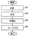
第4の実施形態では、量を計測する方法、量をモデリングする方法、量を分析する方法、量を可視化する方法、及び結果を製造プロセスにフィードバックする方法が開示される。量測定プローブが、ロボットCMMアームのプローブ端に取り付けられる。測定された量を測定中の物体のCADモデルと組み合わせる手段が設けられる。 In a fourth embodiment, a method for measuring quantities, a method for modeling quantities, a method for analyzing quantities, a method for visualizing quantities, and a method for feeding back results to a manufacturing process are disclosed. A quantity measuring probe is attached to the probe end of the Robot CMM Arm. Means are provided for combining the measured quantity with the CAD model of the object being measured.
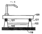
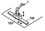
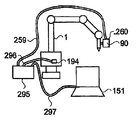
第5の実施形態では、移動式ロボットCMMアームに関する方法及び装置が開示される。ロボットCMMアームが、電気車両に組み込まれた格納可能な足を有する三脚に取り付けられ、或る測定位置から次の測定位置へ移動させられる。これは、車両又は航空機等の大きな物体を自動的に走査するために通常は用いられ、現在用いられている大型の水平タイプ又はブリッジタイプのCMMよりも低価格で柔軟性が高い代替物となる。 In a fifth embodiment, a method and apparatus for a Mobile Robot CMM Arm is disclosed. A Robot CMM Arm is attached to a tripod with retractable legs built into an electric vehicle and moved from one measurement position to the next measurement position. This is typically used to automatically scan large objects such as vehicles or aircraft, and is a cheaper and more flexible alternative to the currently used large horizontal or bridge type CMMs .
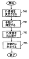
第6の実施形態では、変位可能な外骨格を有するロボットCMMアームの実施形態が開示される。内部CMMアームは、外骨格から変位し、ロボットプログラムを生成するために手動で用いられる。内部CMMアームが外骨格に戻されると、ロボットがロボットプログラムを自動的に実行する。ロボットプログラムを生成するための内部CMMアームの手動操作は、教示ペンダントの使用等の従来の方法よりも高速且つ有用であるという利点を有する。 In a sixth embodiment, an embodiment of a Robot CMM Arm having a displaceable exoskeleton is disclosed. The Internal CMM Arm is displaced from the exoskeleton and used manually to generate a robot program. When the Internal CMM Arm is returned to the exoskeleton, the robot automatically executes the robot program. Manual operation of the Internal CMM Arm to generate the robot program has the advantage of being faster and more useful than conventional methods such as using a teaching pendant.
第7の実施形態では、結合されたCMMアーム及びロボットを備えるロボットCMMアームが開示される。CMMアームは、少なくとも2つの位置、すなわちプローブ端と中間位置とにおいて、ロボットにより支持される。この実施形態は、CMMアーム付近からの熱源を移動させるという利点を有する。 In a seventh embodiment, a Robot CMM Arm comprising a coupled CMM Arm and Robot is disclosed. The CMM arm is supported by the robot in at least two positions: a probe end and an intermediate position. This embodiment has the advantage of moving the heat source from near the CMM arm.
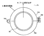
第8の実施形態では、外骨格を有する手動CMMアームが開示される。内部CMMアームは、外骨格により支持及び駆動され、外骨格はさらに作業者により支持及び移動される。現在の手動CMMアームは、作業者が同じアームで操作するように、測定機能、自立機能、及び堅牢性機能を組み合わせる。この第8の実施形態は、測定機能を内部CMMアームに与え、作業者が操作するための支持機能及び堅牢性機能を外骨格に与える。どのような方法で作業者が外骨格を持っても、内部CMMアームは各空間位置で常に全く同じように支持されるため、内部CMMアームに対する荷重が再現可能であり、較正プロセス中の荷重と同じである。この荷重パターンの再現性は、外骨格を有する手動CMMアームが、いかなる既存の手動CMMアームデバイスよりも高精度なデバイスであることを意味する。作業者が無線送信機を有するボタンユニットを外骨格の好都合な場所に取り付けるように、可撓性ボタン手段が設けられ、無線受信機がシステムに組み込まれる。望ましくない衝撃及び荷重から内部CMMアームを守るために、バンプストップ手段が外骨格に設けられる。打撃からプローブを保護し、接触プローブに対する荷重の一部を補償するために、プローブカバーが設けられる。外骨格を有する手動CMMアームと比較して、より小型であり、特に手首及びプローブ領域における操作が改善されているが、依然として著しく高い精度を有する、部分外骨格を有する複数の手動CMMアームが開示される。外骨格と複数の異なる接触プローブ及び非接触プローブとを有する手動CMMアームを用いるための、測定方法が提供される。外骨格を有する手動CMMアームのための自動較正装置及び方法が開示される。輸送中に外骨格を有する手動CMMアームに加わる衝撃荷重の大きさを最小にするために、荷重分散機構を有する輸送ケースが提供される。 In an eighth embodiment, a manual CMM arm having an exoskeleton is disclosed. The internal CMM arm is supported and driven by the exoskeleton, which is further supported and moved by the operator. Current manual CMM arms combine measurement, self-supporting, and ruggedness features so that an operator operates with the same arm. This eighth embodiment provides a measurement function to the internal CMM arm and a support function and a robust function for the operator to operate on the exoskeleton. Whatever way the operator holds the exoskeleton, the internal CMM arm is always supported in exactly the same way at each spatial position, so the load on the internal CMM arm is reproducible, and the load during the calibration process The same. This reproducibility of the load pattern means that a manual CMM arm with an exoskeleton is a more accurate device than any existing manual CMM arm device. Flexible button means are provided and a wireless receiver is incorporated into the system so that the operator can attach the button unit with the wireless transmitter to a convenient location on the exoskeleton. Bump stop means are provided on the exoskeleton to protect the internal CMM Arm from unwanted impacts and loads. A probe cover is provided to protect the probe from hitting and to compensate for some of the load on the contact probe. Disclosed are multiple manual CMM arms with partial exoskeletons that are smaller and have improved maneuverability, especially in the wrist and probe areas, but still have significantly higher accuracy compared to manual CMM arms with exoskeletons Is done. A measurement method is provided for using a manual CMM arm having an exoskeleton and a plurality of different contact and non-contact probes. An automatic calibration apparatus and method for a manual CMM arm having an exoskeleton is disclosed. In order to minimize the magnitude of the impact load applied to the manual CMM arm with the exoskeleton during transport, a transport case with a load distribution mechanism is provided.
第9の実施形態では、保持外骨格を有する手動CMMアームが開示される。外骨格における1つ又は複数の継手は、ブレーキによりロックすることができる。これは、作業者が動作の途中で中断する必要がある場合に、アームがどの位置にあってもロックすることができるため、アームを停止位置に戻す必要がなくなることを意味する。以前のブレーキシステムは、CMMアームに対して作用し、CMMアームに荷重を加えていたが、この実施形態は、内部CMMアームにいかなる荷重も加えずに、外骨格に対して作用するという利点を有する。 In a ninth embodiment, a manual CMM arm having a holding exoskeleton is disclosed. One or more joints in the exoskeleton can be locked by a brake. This means that when the operator needs to be interrupted in the middle of the operation, the arm can be locked at any position, so that it is not necessary to return the arm to the stop position. Previous brake systems acted on the CMM arm and applied a load to the CMM arm, but this embodiment has the advantage of acting on the exoskeleton without applying any load to the internal CMM arm. Have.
第10の実施形態では、本発明の内骨格を有する手動CMMアームの実施形態が開示される。CMMアームは、支持内骨格の外部にある。以前のデバイスでは、カウンターバランス機能は、Romer及びCimcoreのデバイスのようにアームと平行でアームの外部にあったか、又はアームに曲げモーメントが加わるようにアームに埋め込まれていた。本発明は、CMMアームの内側に補償機能を隠すとともに、アームに曲げモーメントを加えずに補償する。 In a tenth embodiment, an embodiment of a manual CMM arm having an endoskeleton of the present invention is disclosed. The CMM arm is outside the supporting endoskeleton. In previous devices, the counterbalance function was either parallel to the arm, like the Romer and Cimcore devices, or external to the arm, or embedded in the arm so that a bending moment was applied to the arm. The present invention hides the compensation function inside the CMM arm and compensates without applying a bending moment to the arm.
第11の実施形態では、内骨格を有するロボットCMMアームが開示される。このCMMアームは、支持及び駆動ロボット内骨格の外部にある。第1の利点は、外部CMMアームが全てのドライブ(drives:駆動機構)を隠すため、アクセスが限られている用途に適したアームが提供されることである。第2の利点は、外部CMMアームがより大きな断面を有し、且つあまり曲がらないため、より高精度になることである。 In an eleventh embodiment, a Robot CMM Arm having an endoskeleton is disclosed. This CMM arm is outside the support and drive robot endoskeleton. The first advantage is that an external CMM arm hides all the drives, thus providing an arm suitable for limited access applications. The second advantage is that the external CMM arm has a larger cross section and does not bend very much, resulting in higher accuracy.
次に、本発明の実施形態を、添付図面を参照して例としてのみ説明する。 Embodiments of the present invention will now be described by way of example only with reference to the accompanying drawings.
[好ましい実施形態の形態]
[第1の実施形態]
可搬式ロボットCMMアーム
本発明の外骨格を有するCMMアームの第1の実施形態は、可搬式ロボットCMMアームである。この可搬式ロボットCMMアームの実施形態は、外骨格によりガイドされる内部CMMアームを備える。外骨格は、高精度な測定ができるように、伝達手段を介して内部CMMアームを支持及び操作する。本発明は、多くのロボットCMMアームの関節アームレイアウトで具現することができる。本発明の第1の実施形態によるロボットCMMアームには、2つの好ましいレイアウト、すなわち、6つの継手を有する6軸型及び7つの継手を有する7軸型がある。
[Preferred Embodiment]
[First Embodiment]
Portable Robot CMM Arm A first embodiment of a CMM arm having an exoskeleton of the present invention is a portable Robot CMM Arm. This embodiment of the portable Robot CMM Arm comprises an Internal CMM Arm guided by an exoskeleton. The exoskeleton supports and manipulates the internal CMM arm via a transmission means so that highly accurate measurements can be made. The present invention can be implemented in the articulated arm layout of many Robot CMM Arms. There are two preferred layouts for the Robot CMM Arm according to the first embodiment of the invention: a 6-axis type with 6 joints and a 7-axis type with 7 joints.
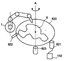
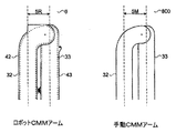
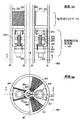
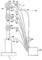
ロボットCMMアームの継手及びセグメントのレイアウト
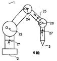
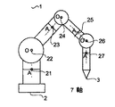
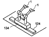
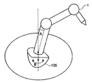
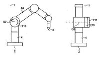
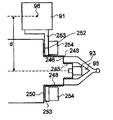
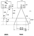
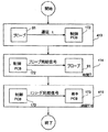
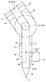
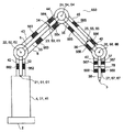
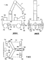
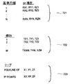
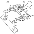
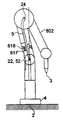
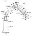
図1A及び図1Bは、本発明の第1の実施形態によるロボットCMMアーム1の好ましい6軸レイアウト及び7軸レイアウトそれぞれを示す図である。関節ロボットCMMアーム1は、ベース端2及びプローブ端3を有し、2端間に一連のセグメント及び回転継手を備える。2つのタイプの継手、軸方向継手及び直交継手がある。軸方向継手(図1A、図1Bでは「A」と記す)は、その2つの隣接するセグメントの共通軸を中心に回転する。直交継手(図1A及び図1Bでは「O」と記す)は、その2つの隣接するセグメント間のヒンジとして回転する。図1Aでは、継手のタイプは、ベース端2からプローブ端3まで順に、AOOAOAであり、これらはそれぞれ継手中心21、22、24、25、26、及び27を指す。図1Bでは、継手のタイプは、ベース端2からプローブ端3まで順に、AOAOAOAであり、これらはそれぞれ継手中心21、22、23、24、25、26、及び27を指す。6軸レイアウトは、7軸レイアウトよりも低費用であるという利点を有する。7軸レイアウトは、6軸レイアウトよりも複雑な物体へのアクセスの柔軟性が高いという利点を有する。
Robot CMM Arm Joint and Segment Layout FIGS. 1A and 1B are diagrams illustrating a preferred 6-axis layout and 7-axis layout of the
図1Bの好ましい7軸ロボットCMMアーム1は、本発明のロボットCMMアーム1のこの第1の実施形態で説明されているが、本発明は、この継手レイアウト又は図1Aの好ましい6軸レイアウトに限定されず、軸受は7つよりも多くても少なくてもよい。単純な用途では、3つの継手で十分であり得る。本発明は、回転移動軸のみに限定されない。以下で開示されるように、本発明は、ベース端2を取り付けることが好ましい1つ又は複数の直線移動軸を備えていてもよい。
Although the preferred 7-axis
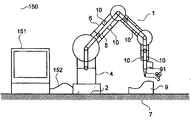
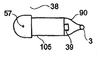
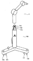
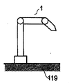
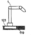
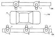
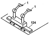
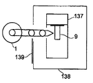
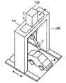
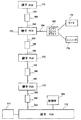
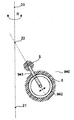
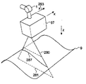
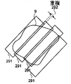
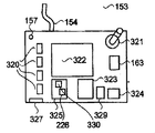
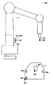
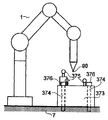
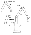
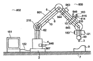
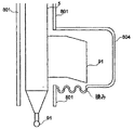
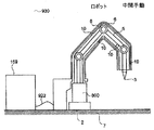
図1cは、ケーブル152によりラップトップコンピュータ151に接続されるロボットCMMアーム1を備える、ロボットCMMアームシステム150を示す。ロボットCMMアーム1は、ベース端2及びプローブ端3を有する。ロボットCMMアーム1は表面7に取り付けられる。ロボットCMMアーム1のプローブ端3には、プローブ90が取り付けられる。ロボットCMMアーム1のプローブ端3付近には、光学プローブ91も取り付けられる。ロボットCMMアーム1は、ベース4、内部CMMアーム5、外骨格6、及び伝達手段10を備える。測定される物体9は、表面7に配置される。
FIG. 1 c shows a Robot
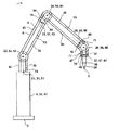
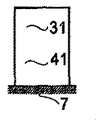
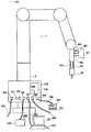
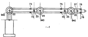
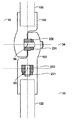
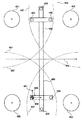
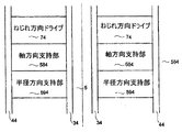
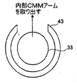
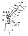
図2は、ロボットCMMアーム1の2つの主要部品、すなわち、内部CMMアーム5及び外骨格6を示し、これらは、共通のベース4と、共通の継手中心21、22、23、24、25、26、及び27とを共有する。内部CMMアーム5は、本明細書中でそれぞれCMMセグメント2〜8と呼ばれる、セグメント32、33、34、35、36、37、及び38を備える。CMMセグメント8 38は、ロボットCMMアーム1のプローブ端3に達する。共通のベース4は、CMMセグメント31とも呼ばれる。内部CMMアーム5はさらに、本明細書中でそれぞれCMM継手1〜7と呼ばれる、継手51、52、53、54、55、56、57を備える。外骨格6は、本明細書中でそれぞれ外骨格セグメント2〜8と呼ばれる、セグメント42、43、44、45、46、47、及び48を備える。外骨格セグメント8 48は、ロボットCMMアーム1のプローブ端3まで達しない。共通のベース4は、外骨格セグメント41とも呼ばれる。外骨格6はさらに、本明細書中でそれぞれ外骨格継手1〜7と呼ばれる、継手61、62、63、64、65、66、及び67を備える。ロボットCMMアーム1はさらに、本明細書中でそれぞれ伝達手段2〜8と呼ばれる、伝達手段72、73、74、75、76、77、及び78を備え、これらは内部CMMアーム5を外骨格6に取り付ける。伝達手段2 72は、CMMセグメント2 32を外骨格セグメント2 42に取り付ける。伝達手段3 73は、CMMセグメント3 33を外骨格セグメント3 43に取り付け、伝達手段4 74、5 75、6 76、7 77、及び8 78に関しても同様である。
FIG. 2 shows two main parts of a
内部CMMアームの継手及びセグメントのレイアウト
ロボットCMMアーム1の内部CMMアーム5のセグメント及び継手は、概して以下のように命名及びレイアウトされる。
Inner CMM Arm Joint and Segment Layout The segments and joints of the

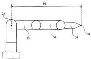
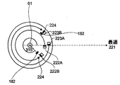
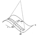
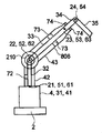
次に図3を参照すると、ロボットCMMアーム1のリーチ80は、CMM継手3〜7がこの距離を最大にするように回転する場合の、継手中心2 22からCMMセグメント8 38のプローブ端3までであると定義される。ロボットCMMアーム1のリーチ80の大部分は、CMMセグメント3 33の長さ及びCMMセグメント5 35の長さの和から成る。
Referring now to FIG. 3, the
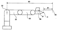
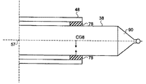
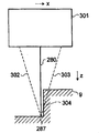
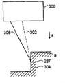
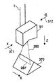
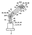
次に図4を参照すると、光学プローブ91がCMMセグメント8 38に取り付けられている場合、リーチ80は、CMMセグメント8 38のプローブ端3と測定が行われ得る測定深さの光学測定中点82との間の距離である仮想リーチ81だけ増加する。
Referring now to FIG. 4, when the
各CMMセグメントは高い剛性を有する。内部CMMアーム5に対して少しでも荷重があると、セグメントの曲げ又はねじれが生じ、内部CMMアーム5の精度を低下させることになる。重力は持続的な荷重源であり、重力の影響は、ロボットCMMアーム1の空間的向きが異なれば異なる。通常の使用時におけるロボットCMMアームの長いCMMセグメントの典型的な最大角度ねじれ傾斜(maximum angular torsional slope)は0.25秒角であるが、特にCMMセグメントの長さに応じて、それよりも大きくても小さくてもよい。通常の使用時におけるロボットCMMアームの長いCMMセグメントの典型的な最大角度曲げ傾斜(maximum angular bending slope)は0.5秒角であるが、長いCMMセグメントの材料、長さ、及び直径に応じて、それよりも大きくても小さくてもよい。
Each CMM segment is highly rigid. If any load is applied to the
各CMMセグメントは、1つ又は複数の重要なアイテムを備える。 Each CMM segment comprises one or more important items.
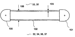
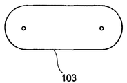
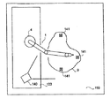
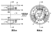
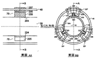
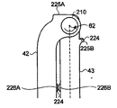
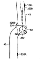
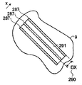
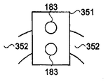
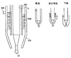
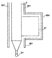
次に図5Aを参照すると、CMMセグメント3 33、5 35は、それぞれ1つの継手を収容する2つの端ハウジング100と101との間に、直径108及び肉厚109を有するリンク部材102を備える。次に図5Bを参照すると、CMMセグメント2 32、4 34、6 36、及び7 37は、各端に1つずつ2つの継手を収容するダブルハウジング103を備える。次に図5C1を参照すると、CMMセグメント8 38は、一端にCMM継手7 57を収容するプローブ端ハウジング105を備え、他端には、プローブ端3で終端するプローブ90が取り付けられるCMMプローブ取り付け手段39がある。CMM継手2 52、4 54、6 56に直交継手を設ける種々のオプションがあることが理解されるであろう。次に図5C2を参照すると、カンチレバーオプション及びインラインオプションが、CMM継手2 52に関して示される。CMM継手2 52、4 54、6 56の好ましいオプションはインライン(in-line:直列)である。ロボットCMMアーム1の範囲は、これらの継手オプションのいずれにも限定されず、任意の他の設計の直交継手を含むことができる。
Referring now to FIG. 5A,
外骨格の継手及びセグメントのレイアウト
ロボットCMMアーム1の外骨格6のセグメント及び継手は、概して以下のように命名及びレイアウトされる。
Exoskeleton Joint and Segment Layout The segments and joints of the
各外骨格セグメントは、1つ又は複数の重要なアイテムを備える。 Each exoskeleton segment comprises one or more important items.
ベースのレイアウト
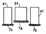
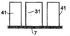
次に図5Dを参照すると、ベース4は、標準3.5インチの強力ねじ(heavy duty thread)116によって取り付け板8に螺入される、軸受中心21を有するCMM継手1 51を収容するCMMセグメント1 31と、ボルト106によってCMMセグメント 31にしっかりと取り付けられる、継手中心21を有する外骨格継手1 61を収容する外骨格セグメント1 41とを備える。取り付け板8は、取り付けボルト107等の取り付け手段104によって表面7に取り付けられる。内部CMMアーム5及び外骨格6の両方が、ベースセグメント31、41をそれぞれ有する。この第1の実施形態では、外骨格セグメント1 41は、座ぐり穴用ボルト(counter-bored bolts)106によりCMMセグメント1 31にしっかりと取り付けられる。次に図5Eを参照すると、本発明のロボットCMMアーム1の別の実施形態では、CMMセグメント1 31が外骨格セグメント1 41に取り付けられないように、CMMセグメント1 31は第1の表面7aに取り付けることができ、外骨格セグメント1 41は第2の表面7bに取り付けることができる。次に図5Fを参照すると、本発明のロボットCMMアーム1のさらなる実施形態では、CMMセグメント1 31及び外骨格セグメント1 41の両方を、同じ表面7に独立して取り付けることができる。表面7とベース2との間にベース延長セクションを設けることにより、CMM継手1 51を表面7からさらに高い位置に上昇させることができる。このようなベース延長セクションは、通常は0.075ppm/℃という低い熱膨張率を有する炭素繊維織物から成る軽量管に基づいていることが好ましい。これは、表面7に対するベース延長管を有するロボットCMMアーム1の測定が、温度の変化に大きな影響を受けないことを意味する。次に図5Gを参照すると、本発明のロボットCMMアーム1のさらなる実施形態では、CMMセグメント1 31を、表面7に取り付けられた外骨格セグメント1 41にしっかりと、又は移動可能に(flexibly)取り付けることができる。次に図5Hを参照すると、本発明のロボットCMMアームのさらなる実施形態では、CMMセグメント1 31及び外骨格セグメント1 41は、表面7に取り付けられた同じベースアイテム4であってもよく、CMMセグメント2 32及び外骨格セグメント2 42の両方が、それぞれCMM継手1 51及び外骨格継手1 61を介してこれに取り付けられる。いかなるベース取り付け形態があってもよいことが、本発明のロボットCMMアームの目的である。
Base Layout Referring now to FIG. 5D, the base 4 houses a CMM joint 151 having a bearing
ロボットCMMアームのリーチ
本発明のロボットCMMアーム1は、この第1の実施形態では、種々のリーチを有する或る範囲の可搬式ロボットCMMアームとして提供される。可搬式ロボットCMMアームのリーチ80は、0.6mから3mまで様々である。本発明の範囲は、この範囲内のリーチに限定されず、リーチ80は、0.6mよりも短くてもよく、又は3mよりも長くてもよい。
Reach of Robot CMM Arm The
内部CMMアームの構造
剛性及び質量
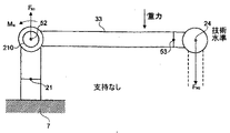
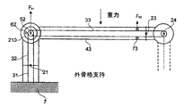
本発明の目的の1つは、内部CMMアーム5の質量を最小にすることである。これによりさらに、剛性が低くてよく、内部CMMアーム5を動かす原動力も少なくてよいため、可搬式ロボットCMMアーム1の質量を最小にすることができ、それによりロボットCMMアーム1の可搬性がより高まる。有益な相乗効果があり、内部CMMアーム5から質量を100g除去するごとに、ロボットCMMアーム1の設計から約250〜400gを除去することができることが、経験により示されている。中程度のリーチを有する内部CMMアーム5の移動部品の典型的な重量は、2.5〜4kgである。内部CMMアーム5に対する、特に内部CMMアームの継手51〜57に対する応力を最小にするために、外骨格6が内部CMMアーム5を支持及び駆動する。使用時には、外骨格6に対する荷重は、重力及び伝達手段10を介して伝達される荷重だけであるべきである。外骨格6は、内部CMMアーム5を常に同じ場所で支持するため、同じ空間的向きで再現可能に荷重が与えられる。比較すると、技術水準の手動CMMアームは、付加的な応力が作業者により加えられるような設計になっており、この応力は、内部CMMアーム5に対する応力よりも著しく高い上に、作業者が把持する位置及び把持の仕方に応じて、異なる荷重場所及び荷重方向で加えられる。これは、内部CMMアーム5が、同様のリーチを有する手動CMMアームほど高い剛性を必要とせず、より軽量であることを意味する。
Internal CMM Arm Structure Rigidity and Mass One of the purposes of the present invention is to minimize the mass of the
リンク部材の直径及び厚さ
リンク部材の直径108が大きいほど、剛性及び精度が高くなる。材料科学の進歩に伴い、より高剛性且つ軽量の新たな材料が利用可能になるにつれて、アームの剛性対重量比は大きくなっている。内部CMMアーム5は、上腕及び下腕、すなわちCMMセグメント3 33、CMMセグメント5 35に、2つの長いリンク部材102を有する。内部CMMアーム5のリンク部材直径108は、40mm〜70mmの範囲である。本発明のロボットCMMアーム1の範囲は、このリンク部材直径に制限されず、70mmよりも長いか、又は40mmよりも短いリンク部材直径を用いてもよい。作業者による操作中には、技術水準の手動CMMアームに対する力及びトルクは、特に、その時点の継手角度と、補償デバイスと、加速度と、作業者により誘発される力及びトルクとの組み合わせに関連する重力から生じる。作業者は、いずれのリンクにも曲げ力を加え得る。この理由から、手動CMMアームは通常、両方のセグメントで同じリンク直径を有する。外骨格6は、内部CMMアーム5の全てのセグメント32〜38をほぼ等しく支持する。この理由から、この第1の実施形態の内部CMMアーム5は、セグメント33及び35の両方で同じリンク部材直径108を有する。本発明のロボットCMMアームの範囲は、均一なリンク部材直径に制限されず、リンク部材直径は異なっていてもよい。リンク部材102は、本質的には、継手又は伝達手段によりいずれかの端で支持される単純なビームである。主な撓みモードは、水平である場合の重力下で生じる。リンク部材102に対して望ましくないモーメントが何もないと仮定すると、リンク部材102の撓みは、リンク部材の厚さ109とは主に無関係である。リンク部材の厚さは非常に薄くすることができ、これが内部CMMアーム5の質量を最小にするという目的と一致していることになる。内部CMMアームのリンク部材厚さ109は、セグメント33及び35の両方で1mm〜1.5mmであることが好ましい。リーチが長いアームほど、リンク部材厚さ109及び/又はリンク部材直径108は通常、剛性を維持するために増加する。リンク部材の直径及び厚さは、種々の設計仕様及び製造制約のために設計プロセスにおいて最適化されるパラメータである。
Link Member Diameter and Thickness The greater the
形状
外骨格セグメント2 42〜8 48は、組み立て中に内部CMMアームセグメントに被さる(pass down over)。内部CMMアームのCMMセグメント32〜38の形状は、できる限り小さい最大半径方向寸法を有するように制約される。最大半径方向寸法を小さくすることにより、外骨格セグメント2 42〜8 48のサイズを小さくすることができ、これにより、本発明のロボットCMMアームが小さくなり、その用途がより柔軟になる。
外骨格構造
性能
ロボットCMMアーム1が可搬式であり、その重量が最小であることが、この第1の実施形態の目的の1つである。この目的は、サイクルタイムを最小にするとともに、それに対応して継手においてより大きな角加速度を得るという要件と両立できない。最大角速度及び最大角加速度に関する性能は、リーチが長いロボットCMMアーム1よりもリーチが短いロボットCMMアームの方が高い。最大継手角速度は通常、20°/秒〜400°/秒の範囲である。外骨格継手1 61〜4 64は、トルクがより大きいため、外骨格継手5 65〜7 67よりも小さい最大角速度を有する。リーチ80が3mと長く、ロボットCMMアームの重量が35kg未満である場合、継手2は通常、20°/秒の最大角速度を有し得る。リーチ80が1m未満と短く、ロボットCMMアームの重量が約20kgである場合、継手7は、400°/秒の最大角速度を有し得る。本発明のロボットCMMアームの範囲は、この範囲の最大角速度に制限されず、継手の最大角速度は、400°/秒よりも大きくてもよく、又は20°/秒よりも小さくてもよい。
Exoskeleton Structure Performance One of the objects of the first embodiment is that the
質量及び剛性
支持機能及び駆動機能を果たすには高剛性が必要ないため、外骨格構造は内部CMMアームよりも剛性が低い。したがって、外骨格構造は軽量であり、ロボットCMMアームの可搬性がより高くなる。所与の性能基準に対して、任意の移動セグメントの質量を減らすと、あまり強力な駆動システムが必要なく、したがって軽量になるという好循環がある。或る範囲の可搬式ロボットCMMアームの通常の質量は、1mのリーチの場合18kgから3mのリーチの場合35kgまで様々である。本発明のロボットCMMアームの範囲は、この範囲の質量に制限されず、最大質量は、35kgよりも重くてもよく、又は18kgよりも軽くてもよい。
Mass and stiffness The exoskeleton structure is less rigid than the internal CMM arm because high stiffness is not required to perform the support and drive functions. Therefore, the exoskeleton structure is light and the portability of the Robot CMM Arm is higher. For a given performance criterion, reducing the mass of any moving segment has a virtuous cycle where less powerful drive systems are required and therefore lighter. The normal mass of a range of portable Robot CMM Arms varies from 18 kg for 1 m reach to 35 kg for 3 m reach. The range of the Robot CMM Arm of the present invention is not limited to this range of mass, and the maximum mass may be heavier than 35 kg or lighter than 18 kg.
形状
外骨格構造は小型であり、内部CMMアームに近接している。これは、ロボットCMMアームが、車内等の測定が困難な領域にアクセスできることを意味する。したがって、ロボットCMMアームは、カーシートを元の位置にあるままで測定することができず、まず車両から取り外さなければならない場合等、物体の大掛かりな準備なしには取り組むことができない用途に適用することができる。外骨格セグメント42〜48は、内部CMMアームセグメント32〜38が使用中に有害な固体、液体、又はガスに曝されないよう保護するために、密閉形状を形成する。外骨格セグメント42〜48は、内部CMMアームセグメント32〜38の上から嵌まるように中空である。外骨格の形状は、ロボットCMMアームを手動で使用可能にする機能も果たし、衝突の場合に内部CMMアームの部品を保護する。外骨格構造の部品は、美的理由から非機能的な表面形状を有する。外骨格の形状を決定する最大要因の1つは、モータ及びギヤボックス駆動要素のサイズ及び場所である。
Shape The exoskeleton structure is small and close to the internal CMM arm. This means that the Robot CMM Arm can access areas that are difficult to measure, such as in a car. Therefore, the Robot CMM Arm applies to applications where the car seat cannot be measured while in its original position and cannot be tackled without extensive preparation of the object, such as when it must first be removed from the vehicle. be able to. Exoskeleton segments 42-48 form a hermetic shape to protect the internal CMM arm segments 32-38 from exposure to harmful solids, liquids, or gases during use. The exoskeleton segments 42-48 are hollow so as to fit over the internal CMM arm segments 32-38. The shape of the exoskeleton also serves to manually enable the Robot CMM Arm and protects the parts of the Internal CMM Arm in the event of a collision. The parts of the exoskeleton structure have a non-functional surface shape for aesthetic reasons. One of the biggest factors determining the shape of the exoskeleton is the size and location of the motor and gearbox drive elements.
材料
内部CMMアームの材料
ハウジング100、101、103、105は、航空機用アルミニウムでできており、アルミニウムは陽極酸化される。リンク部材102は、ゼロに近い熱膨張率、高剛性、及び低密度を提供する、Toray T700等の炭素繊維織物−エポキシ複合材料からできている薄肉管から成る。リンク部材102は、当業者により十分に理解されるように、精密治具で支持しながら、エポキシ等の接着剤により端ハウジング100、101に取り付けることができる。
Material Internal CMM
外骨格の材料
継手ハウジングアイテムは、航空機用アルミニウムでできている。アルミニウムは陽極酸化される。リンクアイテムは、炭素繊維の精密成形品から成る。リンクアイテムは、精密治具で支持しながら、エポキシ等の接着剤により継手ハウジングアイテムに取り付けられる。
Exoskeleton Material The joint housing item is made of aircraft aluminum. Aluminum is anodized. The link item consists of a precision molded product of carbon fiber. The link item is attached to the joint housing item by an adhesive such as epoxy while being supported by a precision jig.
ロボットCMMアームの取り付け
本発明の目的の1つは、使用対象の用途に合うように、複数の異なる取り付け手段を用いて、ロボットCMMアームを複数の異なる構造に種々の向きで取り付けることができることである。
Attachment of Robot CMM Arm One of the objects of the present invention is that the Robot CMM Arm can be attached to different structures in different orientations using different attachment means to suit the intended application. is there.
取り付け手段
表面7へのロボットCMMアーム1の取り付けは、ボルト107によるボルト締め、磁気的取り付け(magnetic mounting:磁着)、真空取り付け、及びクランピングを含む多くの手段104により行うことができる。用いる取り付け手段104は、ロボットCMMアーム1の動作中に取り付け板8と表面7との間に移動をもたらすことにより、ロボットCMMアーム1の精度を低下させないように、十分な剛性を有する。
Attachment means Attachment of the
垂直なロボットCMMアームの向きを有する水平表面
図6を参照すると、ロボットCMMアーム1は通常、標準3.5インチ×8ねじ116を用いて可搬式スタンド110の水平取り付け表面112に取り付けられる。スタンド110は、ロックすることができる3つの車輪111を有する。スタンド10は格納可能な足113を有する。スタンド110は、転倒を避けるために大きな設置面積を有する。手動CMMアームのアーム荷重の一部を作業者の足が受けることにより、スタンド110に対するトルクが減るため、その設置面積は対応する手動CMMアームの設置面積よりも大きい。ロボットCMMアーム1は対応する手動CMMアームよりも重いため、スタンド110の質量は、対応する手動CMMアームスタンドの質量よりも重い。スタンド110は、ロボットCMMアームのベースを昇降させるための伸張可能な垂直部材115を有する。スタンド110は、剛性の高い床表面上で用いられなければならず、カーペット又は圧縮可能な床仕上げ材の上で用いてはならない。スタンド110は、ロボットCMMアームの動力学により揺動されないように、重いことが好ましい。スタンドに取り付けられる可搬式ロボットCMMアームの制御により、スタンド110の揺動及び精度の低下を避けるために、角加速度及び角速度が制限される。リーチが短いロボットCMMアームのスタンド110の一例は、重量が約100kgで、Brunson Instrument Company(米国)により製造される、短いリーチ及び中程度のリーチに適したスタンド番号231−0である。付加的な重りをスタンド110のベースにしっかりと取り付けて、その安定性を高めてもよい。リーチが長いロボットCMMアームには、より大きく頑丈なスタンドが必要である。図7Aを参照すると、ロボットCMMアーム1は、支持体122の上に配置されている防振手段121によって床119に伝わる振動から隔離することができる、光学台又は花崗岩ブロック等の安定したテーブル120に、しっかりと取り付けることができる。図7Bを参照すると、ロボットCMMアーム1は、床119に直接取り付けてもよい。図7Cを参照すると、ロボットCMMアーム1は、床119に取り付けられた定盤123に取り付けてもよい。図7Dの平面図を参照すると、ロボットCMMアーム1は、レール軸124に取り付けられ、レール軸124上で床119を移動する。ロボットCMMアーム1は、レール軸124に沿って3つの異なる位置A、B、Cで示される。これは、ロボットCMMアーム1がはるかに大きな体積の大きな物体9を測定できることを意味する。第2のロボットCMMアーム1が第2のレール軸124に取り付けられ、2つの異なる位置D及びEで示される。2つのレール軸は平行であることが好ましい。これは、2つのロボットCMMアーム1が独立して移動して、自転車、自動車、又は大型車両等の大きな物体9の両側で測定を行うことができることを意味する。レール軸124は直線状であることが好ましい。レール軸124は、取り外し及び異なる場所に設置し直すことができるように、床119の上に取り付けられることが好ましい。代替的に、レール軸124は、床119に永久的に埋め込まれてもよい。レール軸124は、手動式、好ましくはボタンを介した手動の作動に応じたモータ駆動式、又は好ましくはCNC駆動式であり得る。ロボットCMMアーム1は、レール軸124に沿った並進中は静止中ほど安定しない。ロボットCMMアーム1は、レール軸124に沿った並進中は測定を行わず、その代わりに、レール軸124を用いてロボットCMMアーム1を、AからBを経由してCへ等、或る測定場所から別の測定場所へ移動させることが好ましい。しかしながら、ロボットCMMアームは、レール軸124に沿った並進中に測定を行ってもよいが、精度は通常は低下する。この状況は、レール軸124が、ロボットCMMアーム1が取り付けられる大型機械の一部である場合に起こる可能性が最も高い。次に図7Eを参照すると、2つのロボットCMMアーム1を、同じレール軸124に取り付けて、独立して移動させることができる。レール軸124に沿った各ロボットCMMアーム1の移動は、手動式、好ましくはボタンを介した手動の作動に応じたモータ駆動式、又は好ましくはCNC駆動式であり得る。適した用途は、設計室での自動車プロトタイプの測定である。これは、2つのレール軸124それぞれの上を2つずつが独立して移動する4つのロボットCMMアーム1を有する測定設備の生産力が、各レール軸124上にロボットCMMアームが1つしかない測定設備の生産力の2倍であり得ることを意味する。次に図7Fを参照すると、ロボットCMMアーム1は、ロボットCMMアーム1のベースを垂直方向に上下移動させることができる垂直軸133に取り付けられる。垂直軸133は、レール軸124上で水平方向に移動することができる。垂直軸133は、手動式、好ましくはボタンを介した手動の作動に応じたモータ駆動式、又は好ましくはCNC駆動式であり得る。垂直軸133は、図7Dに示すツイン対向ロボットCMMアーム構成の一方又は両方のロボットCMMアーム1に対して設けてもよく、又は垂直軸133は、図7Eに示すロボットCMMアーム構成の一方又は両方のアームに対して設けてもよい。次に図7Gを参照すると、2つのロボットCMMアームが、レール軸124上を移動する移動多アームベース134に取り付けられる。作業範囲(working volume)におけるロボット間の到達不可能なギャップをなくすのに十分な作業重複となるように、2つのロボットCMMアームは、適当な距離Sだけ離れている。これは、2つの独立したロボットCMMアーム1の代わりに移動多アームベース134を1つだけ必要とする低費用で単純な設備により、高い生産力を得ることができることを意味する。先に開示したように、短いロボットCMMアームの方が、長いCMMアームよりも高精度である。水平レール124及び垂直軸133それぞれが、又はこれらの組み合わせが、より短いロボットCMMアームを用いることができることを意味することが、この実施形態の目的の1つである。これは、水平レール124及び垂直軸133がロボットCMMアームよりも長い距離にわたってより高精度であるため、水平レール124及び垂直軸133を個別に又は組み合わせて用いることにより、測定設備の総合精度が高まることを意味する。当業者は、ロボットCMMアームの長さ、水平軸、及び垂直軸の仕様を最適化して、精度を最大にすることができる。次に図7Hを参照すると、ロボットCMMアーム1は、測定すべき物体9に取り付けられる。アダプタ136が用いられる。このような物体9の一例は、腐食している表面領域又はその付近を測定されているガスパイプラインのパイプの一部である。この例では、パイプ付近に十分な安定性を有する一時的構造を設けるよりも、ロボットCMMアーム1をパイプに取り付ける方が容易且つ安価である。アダプタ136は、ロボットCMMアーム1の取り付け及び取り外しを容易にするために磁気的に取り付けられてもよく、又は任意の他の取り付け手段104を用いてもよい。物体9によっては、アダプタ136が必要なく、ロボットCMMアーム1を物体9に直接取り付けてもよい。次に図7Iを参照すると、ロボットCMMアーム1は、物体9が載置される加工機137に隣接して取り付けられる。加工機137は、自動引き戸139を有する筐体138により囲まれる。ロボットCMMアーム1は、加工機137における物体9を測定することができる。加工機137には筐体138及び引き戸139が必要であるが、それは、加工中にロボットCMMアームにとって有害であり得る環境汚染物質が筐体内に含まれるからである。加工機137によっては、ロボットCMMアーム1にとって有害な環境汚染物質を発生させず、引き戸139を有する筐体138を必要としないものもある。リーチ80が短い小型のロボットCMMアーム1は、ロボットCMMアーム1が物体9に近く、物体9に届く範囲内にあるように、加工機137に直接取り付けることができる。加工機137が有害な環境汚染物質を発生させる場合、加工機137に取り付けられたロボットCMMアーム1を保護するために、引き戸が必要である。次に図7Jを参照すると、ロボットCMMアーム1が4つの加工機137それぞれに載置された物体9を測定できるように、ロボットCMMアーム1は、4つの加工機137間に取り付けられる。ロボットCMMアーム1の周りには、いかなる数の加工機137を配置してもよい。次に図7Kを参照すると、ロボットCMMアーム1は、3つの作業領域間142間に取り付けられる。各作業領域は1つの物体9を含み得る。作業領域142は常に、物体9なし、測定すべき物体9、測定中の物体9、測定済みの物体9、又は作業領域142へ、若しくは作業領域142から移送中の物体9、のいずれかを含み得る。ロボットCMMアーム1の周りにはいかなる数の作業領域142があってもよい。作業領域142にある物体9は、ロボットCMMアーム座標系363に対して既知の位置及び向きで治具に正確に位置付けることができる。代替的に、物体9は、人間の目で物体を床上の印と位置合わせすること等、何らかの手段によりおおよその位置付けを行ってもよい。物体9は、当業者に既知の任意の方法により作業領域に位置付けることができる。各作業領域にある各物体9は、異なる部品番号を有する異なる部品であってもよく、又は各物体は同じ部品番号を有する同じ部品であってもよい。ロボットCMMアーム1の周りにいくつかの作業領域142があることの1つの利点は、自動測定のために工作物を一晩中載せたままにすることができるため、ロボットCMMアーム1の利用率が高くなることである。第2の利点は、第1の作業領域142において測定済みの物体9を未測定の物体9と交換し、その間にロボットCMMアーム1は第1の作業領域142において別の物体9を測定していることにより、ロボットCMMアーム1を完全に利用し続けることにある。次に図7Lを参照すると、ロボットCMMアーム1は、物体9が配置される作業領域142を横断する低く堅牢なブリッジ118に取り付けられる。ロボットCMMアーム1及びブリッジ118は、ロボットCMMアーム1のプローブ端3に取り付けられたプローブ90により、物体9の上側全体に対して動作を行うことができるように設計される。物体9は、ブリッジ118の下に嵌まっても依然としてその任意の領域に対して動作を行うことができるように、比較的平坦でなければならない。ロボットCMMアーム1が移動する際に大きな撓みがないように、ブリッジ118は剛性且つ堅牢であり、床119にしっかりと取り付けられる。ロボットCMMアーム1がブリッジに取り付けられるこの実施形態の主な応用分野は、シートメタルの光学検査である。第1のステップにおいて、シートメタルアイテムであり得る物体9は、プレス成形等の上流のプロセスを受ける。第2のステップにおいて、物体9は、作業領域142に手動で移送されて配置される。代替的に、自動コンベヤ又はマテハンロボット等の機構が、作業領域142にあるシートメタルを自動で配置してもよい。第3のステップにおいて、物体9は、ロボットCMMアーム1に取り付けられている少なくとも1つのプローブ90により検査される。第4のステップにおいて、検査プロセスからデータが出力される。データは、検査プロセスで取り込まれたデータを理想的な物体9のCADモデルと自動比較することにより作成することができる。データ出力は、統計的データであっても完全な検査データであってもよい。第5のステップにおいて、物体9は、手動又は自動で作業場から取り除かれる。オプションのステップでは、データ出力を用いて、上流のプロセスを制御するパラメータの変更が、直接又はプロセス統計の収集及び分析を経て行われる。代替的なオプションのステップでは、データ出力を用いて、上流のプロセスで用いられる工具類(tooling)が物理的に変更される。さらなる実施形態では、ロボットCMMアーム1を移動させて大きな物体9を検査するために、直線状のレール124がブリッジ118の上部
に設けられる。代替的な実施形態では、ロボットCMMアーム1は、ブリッジ118に取り付けられる代わりに、作業領域142の片側に取り付けられてロボットCMMアーム1を作業領域142の中央の上に位置決めする、突出支持体の端に取り付けられる。
Horizontal Surface with Vertical Robot CMM Arm Orientation Referring to FIG. 6, the
変位可能な物体及び移動する物体
ロボットCMMアーム1は、物体変位手段上に配置される物体9に対して動作を行うことができ、物体9は、動作中に少なくとも一度変位させられることが、本発明のさらなる目的である。次に図7Mを参照すると、ロボットCMMアーム1は、物体9が軸Aを中心に回転しながら位置付けられる回転テーブル820に隣接して取り付けられる。回転テーブル820は、手動で回転させて、クランプ822により新たな位置にロックすることができる。代替的に、回転テーブル820は、モータ又はサーボドライブ等の電動機構821により回転させてもよい。回転テーブル820の自動回転は、ロボットCMMアームシステム150か、又はボタン又はスレーブ制御手段を介した手動の作動等の任意の他の手段により、制御することができる。回転テーブル820の軸Aには通常、エンコーダ等の角度位置記録デバイス823が取り付けられる。通常のプロセスでは、回転テーブルを90°間隔で4つの位置に移動させることにより、物体9を4回変位させて、ロボットCMMアーム1が物体9の全象限に対して動作を行うようにアクセスできるようにする。この実施形態では、ロボットCMMアーム1は、物体9の移動中は測定等の動作を実行しない。回転テーブル820上で物体9を回転させることの利点は、ロボットCMMアーム1のリーチ80よりも大きな物体90に対して動作を行うことができることであり、これは、幅広の物体又は背の高い物体に特に適している。回転テーブル820上で物体9を回転させることの第2の利点は、各部分にアクセスしにくい複雑な物体9の場合、ロボットCMMアーム1に種々のアクセス向きが与えられることである。次に図7Nを参照すると、ロボットCMMアーム1は、物体9が軸Bに沿って直線変位して位置付けられる、リニアテーブル824に隣接して取り付けられる。リニアテーブル824は、回転テーブル820と同様の位置測定可能性、制御可能性、及び利点を有する。他の実施形態では、2つ以上の軸を有する多軸テーブルを用いて、物体を変位させることができる。各タイプのテーブル軸又は軸の組み合わせは、異なる種類の物体のサイズ及び形状にとって異なる利点を有することが、当業者には理解されるであろう。さらなる実施形態では、ロボットCMMアーム1は固定されており、物体9を移動させながら非接触測定等の動作又は工具を用いた接触動作を実行する。さらなる実施形態では、非接触測定等の動作又は工具を用いた接触動作が行われている間、ロボットCMMアーム1及び物体9の両方が同時に移動する。ロボットCMMアーム1及び物体9の両方が床に対して移動する場合、座標系を物体座標系等の共通の座標系に変換するために、さらなる制御アルゴリズムが必要である。全ての実施形態において、物体9は、物体9とテーブルとの間の相対移動をなくすために、テーブルに、クランプされるか又は他の方法で載置されてもよく、又は載置されなくてもよい。物体9が動作中に移動する全てのテーブルの実施形態において、テーブルは高精度でなければならず、正確な作業を行うことができるように、物体はテーブルに対して移動してはならない。必要なサイズ及び精度のテーブルは、通常は高価なアイテムである。
Displaceable object and moving object The
他のロボットCMMアームの向き
用途によっては、ロボットCMMアーム1は、水平表面ではなく、且つロボットCMMアーム1がほぼ垂直に直立しない向きに取り付けられる。図8Aを参照すると、ロボットCMMアーム1は、壁125に対して直角に取り付けられる。図8Bを参照すると、ロボットCMMアーム1は、ガントリ126から支持される。代替的に、ロボットCMMアーム1は、天井から支持されてもよい。図8Cを参照すると、ロボットCMMアーム1は、垂直線に対して60°の表面を有するプラットフォーム127に取り付けられる。図8D及び図8Eを参照すると、ロボットCMMアーム1は、自動車企業で用いられるような従来の大型3軸CMMに取り付けられる。水平アームCMM128及び移動ブリッジCMM129を含む、多くのタイプの従来の3軸CMMがある。ロボットCMMアーム1はかなりの質量を有し、通常はその精度及びアームのリーチに応じて18〜32kgの重量があると予測されるが、それよりも重くても軽くてもよい。従来のCMMに取り付ける場合、本発明に基づいた軽量のロボットCMMアームは、実質的に12kg未満の質量を有するように設計することができる。ロボットCMMアーム1が従来のCMMに取り付けられる自動車用途の場合、図8Eに示すように、ロボットCMMアームは、移動ブリッジCMM129に取り付けられて、ブリッジ131の垂直柱130から垂直下方に支持されることが好ましい。このモードでは、移動ブリッジCMM129の移動とロボットCMMアーム1の移動との組み合わせにより、ロボットCMMアーム1は、測定中の物体9の全部品にアクセスすることができる。本発明の範囲は、3つの直線軸を有するブリッジタイプの従来の3軸CMM131の垂直柱130から、又は同様に3つの直線軸を有する水平アームCMM128の水平アーム132から、垂直下方に取り付けられるロボットCMMアーム1に限定されない。ロボットCMMアーム1は、任意数の軸を有する任意の向きの、任意の実質的に従来のCMMから取り付けることができる。次に図8Fを参照すると、ロボットCMMアーム1は、垂直回転軸Bに対して角度Aで、回転ウェッジベース135に取り付けられる。
Other Robot CMM Arm Orientation In some applications, the
本発明の範囲は、図7A〜図7G及び図8A〜図8Fに示すロボットCMMアームの設置の実施形態に限定されない。本発明の目的の1つは、ロボットCMMアーム1を任意の向きで自由空間に取り付けることができることである。ロボットCMMアーム1を固定構造又は可動構造から取り付けることができることが、本発明のさらなる目的である。ロボットCMMアーム1を任意の移動構造に取り付けて、ロボットCMMアームを6自由度で並進させるか又は方向付けることができることが、本発明のさらなる目的である。移動構造は、測定中又は測定間のいつでも移動させることができる。ロボットCMMアーム1を、任意の数量及び任意の配置で設備に設けることができることが、本発明のさらなる目的である。
The scope of the present invention is not limited to the embodiment of the Robot CMM Arm installation shown in FIGS. 7A-7G and 8A-8F. One of the objects of the present invention is that the
硬質及び非硬質の取り付け台
ロボットCMMアーム1は、測定中の物体9に対して硬質である表面7に取り付けられることが好ましい。場合によっては、ロボットCMMアーム1と測定中の物体9との間には、大型の機械が近くで動作して床に振動を伝えることにより引き起こされるような、連続する相対移動があり得る。又は、ロボットCMMアーム1と測定中の物体9との間には、大型トラックが通り過ぎること、又は測定中の物体が偶発的な打撃を受けることにより引き起こされるような、不定期の相対移動があり得る。又は、ロボットCMMアーム1と測定中の物体9との間には、ロボットCMMアームが取り付けられるとともに物体が載置される構造の熱膨張により引き起こされるような、低速の相対移動があり得る。ロボットCMMアーム1のベース端4とロボットCMMアーム1が測定中の物体9との間の相対移動の事例を示す図9を参照すると、6自由度の相対移動を、独立した測定デバイスにより測定することができる。このような独立した測定デバイスの例は、Leica製のレーザトラッカ及び好ましくはKrypton製の写真測量トラッカ140である。ロボットCMMアーム1及び写真測量トラッカ140は、定盤123に取り付けられる。物体9は、床119に載せられ、物体9が定盤123に対して大きな相対移動をするように移動させられる。写真測量標的141は、最低3つで好ましくは4つ以上の標的が、測定プロセス中のいつでも写真測量トラッカ140に見えるように、物体9に取り付けられる。写真測量トラッカ140による相対移動の測定は、ロボットCMMアーム1の測定と時間的に同期することが重要である。時間同期は、測定デバイスを同時にトリガすること、後で処理するために共通のクロックにより全測定にタイムスタンプ(time stamping:時刻記録)することを含む、当業者には一般に既知の任意の方法により行うことができる。このような処理は、相対移動測定及びロボットCMMアームの測定が同時に行われない場合の時間的補間を含み得る。ロボットCMMアーム1の測定値に対して写真測量トラッカ140の測定値を較正するプロセスは、当業者には既知である。その結果、物体9の測定値は、ロボットCMMアーム1と物体9との間の測定された相対移動に関して補正される。
Rigid and non-rigid mounting platform The
ロボットCMMアームの範囲
ロボットCMMアーム1のリーチ80は、用途に応じて異なる。この第1の実施形態のロボットCMMアーム1は、種々のリーチ80を有する或る範囲の可搬式ロボットCMMアーム1として提供される。例示的な理由のみから、これらのリーチ80は、0.5m〜5mであり得るが、構成部品購入者が要望する可能性が最も高いのは1m〜1.5mのリーチ80であり、自動車関係の購入者が最も要望するのは2m〜3.5mのリーチ80であり、航空宇宙関係の購入者が最も要望するのは2.5m〜5mのリーチ80である。本発明のロボットCMMアーム1のリーチ80は、この開示に制限されない。ロボットCMMアームのリーチ80は、上記の範囲より長くても短くてもよい。ロボット外骨格を用いて内部CMMアームを支持することは、ロボットCMMアームが手動CMMアームの事実上の限界である2mよりも長いリーチを有することができることを意味する。これは、2mよりも長いリーチを必要とする用途(このような用途のための手動CMMアームで実用可能なものは供給されていない)が、ロボットCMMアームにより実行できることを意味する。ロボットCMMアーム1のこの第1の実施形態は、可搬式システムであり、ロボットCMMアーム1の重量を制限するために、大きな角速度及び角加速度用には設計されない。ロボットCMMアーム1の他の実施形態は、はるかに大きな角速度及び角加速度用に設計することができる。この範囲のロボットCMMアーム1全てで同じ駆動系要素を保持するために、この第1の実施形態では、リーチが長いほど受け入れられる最大角速度は小さい。この範囲内での重要な違いは、様々なリンク102の長さである。可搬式ロボットCMMアームには、2つ以上の範囲、例えば、0.6〜1.2m及び1.5〜3mのリーチ80があってもよい。
Range of Robot CMM Arm The reach 80 of the
ロボットCMMアームシステムの概説
次に図10を参照すると、ロボットCMMアームシステム150のこの第1の実施形態のアーキテクチャが記載されている。ロボットCMMアーム1のベース4には、制御ボックス159が取り付けられる。電源コネクタ195に接続された電源ケーブル155によって、電力が供給される。電源スイッチ156及びパワーLED157が設けられる。特に、プローブボックスを介してプローブボックス295をアームケーブル296に接続するために、インタフェースコネクタ194が設けられる。ラップトップコンピュータ151が、ラップトップ通信ケーブル152によってラップトップコネクタ197に接続される。ペンダント153が、ペンダント通信ケーブル154によってペンダントコネクタ198に接続される。ネットワーク200が、ネットワークコネクタ199を介して接続される。ペンダント153及びラップトップコンピュータ151はいずれも、バッテリー163、164によってしばらくの間動作することができる。ペンダントバッテリー163は、電気接点328を有する充電ポイント158にペンダントを配置することにより充電され、ペンダントが充電ポイントに正しく配置されると、自動的に電源接続が確立される。ラップトップバッテリー164は、商用電源から充電される。タッチトリガプローブ92は、ロボットCMMアーム1に取り付けられている場合、自動電源接続160及びトリガ接続を確立する。光学プローブ91は、ロボットCMMアーム1に取り付けられている場合、自動電源接続160、トリガ接続161、及び通信接続162を確立する。
Robot CMM Arm System Overview Referring now to FIG. 10, the architecture of this first embodiment of the Robot
次に図11Aを参照して、ロボットCMMアーム1の内部アーキテクチャを説明する。制御PCB172が、接地ライン165及び+5ボルトパワーレール166に接続される。各外骨格継手1 61〜7 67をそれぞれが駆動する7つのモータ176が、モータケーブル196によって7つの増幅器175に接続され、制御PCB172から増幅器175へ出力される7つの+/−10V制御信号168によって駆動される。制御PCB172は、シリアルバス169によって7つの継手PCB173に接続される。制御PCB172は、ラップトップコンピュータ151及びペンダント153とそれぞれ通信するために、2つのさらなる通信接続152及び154を有する。+24ボルトパワーレール167は、増幅器175に電力を供給する。電源ユニット171が、電源ケーブル155、バッテリー170、接地165、及びパワーレール166、167に接続される。少なくとも1つの継手PCB173が、電源160、トリガ161、及び適用可能な場合は通信162によってプローブ90に接続される。7つのモータ176全てが、継手PCB173からの信号により駆動されるブレーキ177を有する。内部CMMアーム5は、継手PCB173に取り付けられた7つのCMMエンコーダ178を備える。外骨格6を駆動する7つのモータ176に取り付けられる7つのエンコーダ179が、継手PCB173に接続される。内部CMMアーム5に取り付けられる熱電対180が、各継手PCB173に接続される。内部CMMアーム5に取り付けられる歪みゲージ181が、各継手PCB173に接続される。2つのリミットスイッチ182が、各継手PCB182に接続される。2つの作業者ボタン183が、第7の継手の継手PCB173に接続される。タッチセンサ184が、各継手PCB173に接続される。各継手PCB173は、接地ライン165及び+5ボルトパワーレール166に接続される。トリガバス174が、各継手PCB173及び制御PCB172に接続され、7つのCMMエンコーダ178をラッチするために用いられる。
Next, the internal architecture of the
次に図11Bを参照して、ケーブル配線が少なく、無限に回転する軸方向継手が可能であり、より軽量、安価、且つ堅牢である、ロボットCMMアーム1の内部アーキテクチャの代替的なシステムの実施形態を説明する。制御PCB172及び4つの継手PCB173が、各軸方向CMM継手1 51、3 53、5 55、7 57に位置する4つのスリップリングユニット188を通るバス193によって、直列に接続される。1つ〜3つの継手が各継手PCB173により駆動され、制御PCB172も1つ又は複数の継手を駆動することができる。各スリップリングユニット188は、28本分の配線容量を有するが、線(wires)の数は28本よりも多くても少なくてもよい。バス193も28本の線を有する。バス193のこれら28本の線は、内部CMMアーム5、外骨格6、及びプローブ90において継手中心 21の後に位置付けられる構成部品の全機能のための、電圧、接地、シリアルバス、制御バス、及び信号線を保持する。制御バス394は、バス193に組み込まれ、5本の線を用いる。制御バス394は、専用であってもよく、又はCANバス等標準のものであってもよい。CANバスは、高速低レイテンシ制御バスである。CANバス及び関連する回路は、7軸を駆動する場合に限界がある。制御をより高速にする解決手段は、2つのCANバスを用いて、第1のCANバスで4軸を駆動し、第2のCANバスで3軸を駆動することである。余分な5本の線を犠牲にして2つのCANバスを用いることにより、高速の1ミリ秒のサーボループが可能となる。インテリジェント駆動増幅器175が、各モータ176の隣に位置付けられ、制御バス394並びに24Vパワー及び0V接地によって継手PCB173又は制御PCB172に接続される。インテリジェント駆動増幅器175の例は、Maxon Motor(米国)により供給されているEPOS 24/1及び24/5である。代替的に、インテリジェント駆動増幅器の機能は、継手PCB173及び制御PCB172に組み込むことができる。サーボループを閉じることを含む制御機能は、制御部395で行われる。制御部395は、Trio Motion Technology(英国)により供給されているPCI208である。PCI208は、高速サーボ制御を可能にする2つの制御バス394出力を有する。これらの制御バス394出力は、CANバス標準である。CANバスの5〜10本の線は、通常はモータ176から制御部395までの全域にわたって直接配線される7つのモータ/エンコーダそれぞれのための約10本の線の代わりとなる。スリップリング188における線の数は、サイズ及び重量等の実用上の考慮事項により制限されるため、制御バス394を用いてアーム内の線の数を約60本減らすことにより、軸方向CMM継手1 51、3 53、5 55、7 57に無限回転を与えるスリップリング188の使用が可能となる。バス193は、接触式又は非接触式であり得る1つ又は複数のプローブ90に電力、信号、及び通信を提供し、プローブ90の中では、ストライププローブ97が最も一般的に用いられる。第三者が独自に開発したプローブ90をロボットCMMアーム1に取り付ける場合、本発明の目的の1つは、バス193を介してインタフェースコネクタ194から外へスルーチャネルを設けることである。このように、第三者プローブ90の提供者は、ロボットCMMアームシステム150の配線仕様制限内で要求される、電力、接地、信号、及びバスのいかなる組み合わせについても、スルーチャネルを用いることができる。スルーチャネルに設けられる線の典型的な数は9本であるが、9本より少なくても多くてもよい。インタフェースコネクタ194もまた、ロボットCMMアーム1とプローブ90とを同期させるための同期化信号接続を提供することができる。
Referring now to FIG. 11B, an alternative system implementation of the internal architecture of the
本発明の範囲は、この第1の実施形態に開示されるロボットCMMアームシステム150のアーキテクチャに限定されず、ロボットCMMアームシステム150の技術的効果を有する全てのアーキテクチャを含む。例えば、さらなる実施形態では、制御ボックス159は、ロボットCMMアーム1から分離されて、ケーブルによってロボットCMMアームのベース4に接続される。ロボットCMMアームが可搬式にされる場合、制御ボックス159内のアイテムにより、ベース4に無理なく嵌まらないほど制御ボックス159を大きくする必要があるようなロボットCMMアームには、このアーキテクチャが必要であり得る。可搬式ロボットCMMアームは、別個の制御ボックス159の製造費用及び設置面積を増やすことのない単一ユニットであるため、第1の実施形態のアーキテクチャは好ましい。さらに別の実施形態では、ラップトップコンピュータ151の代わりにフルサイズのパーソナルコンピュータを用い、制御PCB172は、パーソナルコンピュータのPCIバス等の標準バスに取り付けられる。代替的に、ラック内のいくつかのコンピュータのネットワークが用いられる。さらなる実施形態では、ペンダントは供給されず、ラップトップコンピュータ151を用いてロボットCMMアーム1が制御される。さらなる実施形態では、制御部395により駆動される1つ又は複数の外部軸をロボットCMMアーム1に接続するためのコネクタが供給される。このような外部軸の例は、直線状レール又はターンテーブルである。
The scope of the present invention is not limited to the architecture of the Robot
内部CMMアームのエンコーダ
内部CMMアーム5は、各CMM継手51〜57に角度エンコーダ178を備える。本発明の範囲は、角度エンコーダ又は任意の特定の設計の角度エンコーダに限定されず、いかなる高精度な形態の角度測定デバイスを利用してもよい。角度エンコーダの分解能及び精度は、エンコーダの直径、印刷可能なエッジの数、エッジの直線性、読み取りヘッドの直線性、補間の量、及びエンコーダの不規則性を含む、いくつかの要因により制限される。ロボットCMMアーム1の精度を最適化するために、内部CMMアーム5の先端(tip end)3側よりも、ベース端2側により高精度な角度エンコーダを有することが望ましい。これは、21、22等のベース端継手がわずかに回転すると、先端3が大きく移動するからである。一方、25、26、又は27等の先端3の継手がわずかに回転すると、先端3はわずかに移動する。他の因子が全て制御されている場合、所与の継手回転に対する先端の移動は、先端3からの継手の距離に比例する。内部CMMアーム5は、Renishaw又はMicro-E Systems(米国)により製造されているもの等のCMMエンコーダ178を用いる。CMMエンコーダ178からプローブ端3までの距離が長いため、内部CMMアーム5のベース端2側のCMM継手21、22は大径のエンコーダを有する。エンコーダ178からプローブ端3までの距離が中程度であるため、内部CMMアーム5の肘における中間継手23及び24は中径のエンコーダを有する。エンコーダ178からプローブ端3までの距離が短いため、内部CMMアーム5の手首における遠位の継手25〜27は小径のエンコーダを有する。エンコーダの直径が小さいほど、完全に伸ばした状態で作業者により保持されるアームの重量が減り、小型になり、取り扱いやすくなる。光学プローブ91により仮想リーチ81が長くなる場合、アームのプローブ端側の継手23〜27に高分解能のエンコーダを有することが重要であり得る。角度エンコーダの背景となる技術が向上し、所与の精度を有する角度エンコーダの直径及び重量が減ることが予測される。次に図12Aを参照すると、内部CMMアームエンコーダ178は、20ミクロンのスケールピッチを有するRenishaw RESR角度エンコーダ185を備え、この角度エンコーダ185は、継手ごとに1つ又は複数のRenishaw RGH20読み取りヘッド186とともに用いられる。エンコーダ185ごとに2つ以上の読み取りヘッド186が取り付けられる場合、読み取りヘッド186は、図12に示すように互いに対して90°で、又は好ましくは互いに対して180°で取り付けられるが、読み取りヘッドは互いに対して任意の他の角度であってもよい。CMM継手23〜27それぞれでは、8192カウントの52mm直径RESRが用いられ、継手ごとに+/−5.6秒角の見積もり(quoted)精度を提供する。CMM継手21及び22それぞれでは、23,600カウントの150mm直径RESRが用いられ、継手ごとに+/−1.9秒角の見積もり精度を提供する。各Renishaw読み取りヘッド186の出力は、Renishaw RGEインタポレータ187に送られる。各Renishawインタポレータ187からの出力は、継手PCB173に供給される。2つ以上の読み取りヘッドを用いる利点は2つある。第1に、エンコーダの偏心取り付け、読み取りヘッドの位置合わせ不良、エッジ印刷の非直線性、読み取りヘッドの非直線性、不規則性、及び他の機械的/位置合わせ誤差のいずれかによる誤差を、単純な平均化により改善又は補償することができる。第2に、動作時に、同じエンコーダ185に対する2つ以上のインタポレータ187からの読み取り値の平均化を、継手PCB173で行うことができ、エンコーダ精度がいくらか改善される。代替的な実施形態では、角度エンコーダシステムを、エンコーダ、1つ又は複数の読み取りヘッド、インタポレータ、平均化、及び誤差マッピングを備える単一ユニットとして設け、角度エンコーダシステムから継手PCB173までの接続を1つにすることができる。Renishaw等の企業が、0.1秒角の精度を有し約50mmの直径を有するような角度エンコーダシステムを将来提供することが予測される。
Internal CMM Arm Encoder The
デュアルパターンエンコーダ
本発明のロボットCMMアーム1に設けられるエンコーダの精度は、ロボットCMMアーム1の精度の重要な要因である。本発明の目的の1つは、2つの読み取りヘッドを有するシングルパターンエンコーダよりも高精度な、パターンごとに1つの読み取りヘッドを有する新規のデュアルパターンエンコーダを提供することである。次に図12Bを参照すると、デュアルパターンエンコーダ860は、2つの面A、Bそれぞれの円周にエッジパターン862が印刷されたエンコーダディスク861を備え、1つの読み取りヘッド186が面Aのパターン862を読み取り、第2の読み取りヘッド186が面Bのパターン862を読み取り、これら2つの読み取りヘッドは、約180°離れて配置される。次に図12Cを参照すると、Aerotech Inc(米国)により提供されるABR1000等の高精度回転ステージ864と、高精度回転ステージ864の回転部分上にディスク861をクランプする異形ボルト等の回転クランプ機構865と、互いに約180°離れて、且つディスク861の反対側に配置されることにより、パターン862が固定読み取りヘッド186に対して移動すると、第1の読み取りヘッド186が面Aのパターン862を読み取ることができ、第2の読み取りヘッド186が面Bのパターン862を読み取ることができる、2つの固定読み取りヘッド186と、ケーブル868によって高精度回転ステージ864及び読み取りヘッド186に接続されるマッピングシステム866とを備える、デュアルパターンエンコーダマッピング装置863が提供される。高精度回転ステージ864は、デュアルパターンエンコーダ860が果たすと予測される精度よりもはるかに高い精度を有する。マッピングシステム866は、(a)高精度回転ステージ864の移動を制御し、(b)読み取りヘッド186から信号を読み取り、(c)マップ867を出力する。次に図12Dを参照すると、パターンAの中心869、パターンBの中心870、及びデュアルパターンエンコーダ860を保持する継手の軸の回転中心871が表されるディスク861が示されている。マップ867は、デジタルファイルであり、(i)2つのパターン862の互いに対する位置ずれの大きさM、(ii)位置ずれの向き872、(iii)高精度回転ステージ864と各パターン862の印刷されたエッジとの間の角度誤差をマッピングし、且つ少なくとも各パターン862のエッジの印刷の非直線性をカバーする、各パターン862に関する誤差マップ、を提供するマッピング情報を含む。2つのパターン862は、印刷されて、通常は10ミクロンの軸方向位置ずれMと適切に位置合わせされるが、この位置ずれMは、10ミクロンよりも大きくても小さくてもよい。位置ずれMの向き872は、ディスク861上に手動でマーキングされる。面A及びBは、ディスク861上に手動でマーキングされる。位置ずれの向き872は通常、読み取りヘッド186により読み取られるパターン862の絶対基準マークを基準にして分かる。マップ867を生成するプロセスは、当業者には既知である。各パターン862の基準マークは、誤差マップを参照するために提供される。
Dual Pattern Encoder The accuracy of the encoder provided in the
ロボットCMMアーム1には、最大7つのマッピングされるデュアルパターンエンコーダ860を設けることができる。マップ867は、各デュアルパターンエンコーダ860に提供される。エンコーダ較正プロセスにおいて、デュアルパターンエンコーダ860があるロボットCMMアーム1の継手が、通常は5°のステップを用いて一方の回転軸限界から他方の回転軸限界へステップするが、ステップは5°よりも大きくても小さくてもよい。各読み取りヘッド186からの読み取り値が各ステップで取られて、読み取り値のセットが形成される。読み取り値のセットは、マップ867の誤差マップを用いて補正され、補正読み取り値が提供される。当業者には十分に理解されるプロセスにおいて、補正読み取り値は、マップ867における位置ずれ及び位置ずれ向き情報を用いて処理され、パターンAの中心869及びパターンBの中心870に対する継手中心871の位置が計算される。較正後、ロボットCMMアーム1が使用中である場合、パターンAの中心869及びパターンBの中心870に対する継手中心871の補正された位置を用いて、デュアルパターンエンコーダ860からの読み取り値を補正し、ロボットCMMアーム1の精度を高める。較正されたデュアルパターンエンコーダ860は、2つの読み取りヘッドを有する同等のシングルパターンエンコーダよりも角度の精度を高めるが、それは(a)1つではなく事実上2つの独立した誤差マッピングされるエンコーダシステムがあり、これら2つのシステムの結果により、1つのパターンのエンコーダシステムよりも確実な平均が提供され、(b)継手軸に対してディスク861が非垂直であることによる誤差が、自動的に平均化されるからである。デュアルパターンエンコーダ860は、2つの読み取りヘッドを有する同等のシングルパターンエンコーダと同じ数の構成部品を有し、同じ重量を有し、同じ体積を占める。代替的な実施形態では、デュアルパターンエンコーダ860には、両方のパターン862が内側放射状パターン及び外側放射状パターンの形態で、ディスク861の同じ面に設けられてもよい。より低費用のデュアルパターンエンコーダ860に関するさらなる実施形態では、パターン862が、ディスク861の製造プロセスにおいて十分に小さい位置ずれMと位置合わせされる場合、デュアルパターンエンコーダ860をマッピングする追加プロセスを有する必要がなく、それでもロボットCMM1の継手に嵌める際のいかなる軸方向位置ずれも自動的に平均化されるという利益が得られる。より高精度なロボットCMM1の代替的な実施形態では、2つのデュアルパターンエンコーダ860が、各継手に設けられ、好ましくは継手中心の両側に位置付けられる。
The
外骨格駆動システムの構造
環境放出物
本発明の目的の1つは、可搬式ロボットCMMアームは動作が静かであり、オフィス環境で用いることができることである。発生する可聴雑音のレベルは、設計において最小限に抑えることが重要である。本質的に低雑音の、モータを含む駆動システム及び伝動方法が、可聴雑音の発生を最小にするために選択される。基本的に、可聴雑音出力のレベルは、ロボットCMMアームが駆動される速度及び加速度とともに上昇する。多くの用途において、速度及び加速度を小さくしてもサイクルタイムにはほとんど影響を及ぼさない。これは、通常はサイクルタイムの90%が、遅いプロセスである測定で占められ、速度を上げることによって10%しか減らすことができないからである。発生する可聴雑音のレベルを最小にすることが重要な使用基準である場合、低速度及び低加速度で静かに走査するように、ユーザが制御システムを設定することができる。ロボットCMMアームは、電磁放射線が少ない駆動システム構成部品を組み込み、且つほとんどの電磁放射線を放出する構成部品の周りに遮蔽を設けることにより、電磁放射線の放出を最小にする。
Structure of Exoskeleton Drive System Environmental Emissions One object of the present invention is that the portable Robot CMM Arm is quiet in operation and can be used in an office environment. It is important to minimize the level of audible noise generated in the design. Inherently low noise drive systems and transmission methods including motors are selected to minimize the generation of audible noise. Basically, the level of audible noise output increases with the speed and acceleration at which the Robot CMM Arm is driven. In many applications, reducing the speed and acceleration has little effect on the cycle time. This is because typically 90% of the cycle time is occupied by measurements that are slow processes and can only be reduced by 10% by increasing the speed. If minimizing the level of audible noise generated is an important usage criterion, the user can set the control system to scan quietly at low speed and low acceleration. The Robot CMM Arm incorporates drive system components that are low in electromagnetic radiation and provides shielding around the components that emit most of the electromagnetic radiation, thereby minimizing the emission of electromagnetic radiation.
熱移動
本発明の目的の1つは、外骨格6のモータ176及び他の駆動構成部品から内部CMMアーム5への熱移動を最小にして、比較的安定した均一な温度によって内部CMMアーム5の精度を高めることである。以下のことが開示される。
−伝導による熱移動をなくすために、外骨格のモータ176から内部CMMアーム5まで有意な直接伝熱リンクはない。伝達手段10は小さく、その材料の熱伝導率は小さい。制御ボックス159内の高温アイテムのいずれも、ロボットCMMアームのベース4に直接取り付けられない。これは、制御ボックス159内の高温アイテムとロボットCMMアームのベース4との間に伝導がないことを意味する。
−内部CMMアームセグメント32〜38は、モータ176から内部CMMアーム5への放射による熱移動を最小にするために被覆される。
−モータは、十分な通気が確保され、且つヒートシンクが設けられることにより、対流により熱移動を最大にして動作温度を最小にする。動作中の継手の角速度は、モータ176の過熱を避けるようにプログラムされる。
−次に図13Aを参照すると、内部CMMアームセグメント32〜38と外骨格セグメント2 42〜8 48との間には、導管189がある。ベース4に配置された大型フィルタ191を有する低能力ファン(low-capacity fan)190が空気192を吸い込み、内部CMMアーム5と外骨格6との間の導管189に沿って吹き出す。空気192の大部分は、内部CMMアームセグメント38と外骨格セグメント8 48との間の先端3から出る。この強制空気循環は、対流により効率的な冷却をもたらす。ファン190は、オフィス環境で静かに動作するように選択される。フィルタ191は、大型且つfieである。オフィス環境で動作する場合、フィルタ191は交換又は洗浄が5年間不要であるべきである。ファン190により吸い込まれる空気192の一部は、制御ボックスを通過して制御ボックス159の通気孔353から出る。この空気循環により、制御PCB172、PSU171、及び増幅器175を含む制御アイテムから熱が除去される。
Heat Transfer One of the objects of the present invention is to minimize the heat transfer from the
-There is no significant direct heat transfer link from the
Internal CMM arm segments 32-38 are coated to minimize heat transfer due to radiation from
The motor has sufficient ventilation and is provided with a heat sink to maximize heat transfer by convection and minimize operating temperature; The angular speed of the joint in operation is programmed to avoid overheating of the
-Referring now to Figure 13A, there is a
外骨格駆動システム
ロボットCMMアーム1は、エンコーダを有するブラシDCサーボモータである電気モータ176により駆動される。本発明の駆動システムは、いかなる種類の電気モータにも限定されず、油圧又は空気圧を含む或る範囲の種々のパワーシステムにより駆動することができる。油圧及び空気圧は、エンコーダを有する電気モータよりもロボットCMMアームに振動を伝えにくい。電気モータ176は、AC又はDCサーボモータ、ステッパモータ、又は他の形態のモータであり得る。モータ176は、ブラシモータであってもブラシレスモータであってもよい。電気モータ176及びエンコーダ179がループを閉じる高速制御ループが提供され、この高速ループは、ロボットCMMアーム1内にうまく組まれる。接触測定を行う場合、内部CMMアーム5の端にある硬質プローブは、接触が行われると動きを止めるが、ロボットCMMアームは動き続ける。接触測定の場合、CMMエンコーダ178を用いて高速制御ループの外部で低レベル又は高レベルのループを閉じる高精度制御ループが提供される。製造費用を削減し、ロボットCMMアームの重量を減らし、且つより小型の構造を生産するために、CMMエンコーダ178を位置フィードバックに用いることができ、その場合、外骨格エンコーダ179は必要ない。製造費用をさらに削減するために、制御ループにおいて位置検知を全く用いずに、ステッパモータを開ループ形式で用いることができる。用途によっては、ロボットCMMアームの加速度は小さくてよく、あまり強力な駆動システムを必要としない。大きな加速度を必要とし、より強力な駆動システムを必要とする用途もある。自動車生産ラインの用途では、車体による衝撃に耐える頑丈なロボットCMMアーム1が必要である。内部CMMアーム5があることにより、ほとんどの用途では、ドライブトレイン要素のバックラッシを少なくすることは必須ではない。ベルトドライブ等、低費用及び低質量のドライブトレイン構成部品を用いることができる。この実施形態では、1つのモータ176が各継手61〜67の駆動に用いられる。
Exoskeleton Drive System The
ロボット動力学
ロボットCMMアームの慣性モーメントをできる限り最小にすることが有益であることは、当業者には理解されるであろう。継手の角加速度及び最大角速度を規定する所与の性能仕様に関して、別のロボットCMMアームよりも慣性モーメントが小さいロボットMCMアームは、プロセスを行うのにより小さいエネルギーを用いる。モータ等の駆動ユニットは、質量の集中により重くなる傾向がある。(a)駆動ユニットをできる限りロボットCMMアームのベース端の近くに配置すること、(b)駆動ユニットの質量を減らすこと、(c)ロボットCMMアームのセグメントの質量を減らすこと、が有益である。1つの駆動ユニットをロボットCMMアームのベース端の近くに移動させる際、移動させた駆動ユニットとベースとの間にある駆動ユニットは、ベース端の近くに移動させた駆動ユニットを動かすのにそれほど激しく働く必要がないため、これら前者の駆動ユニットの仕様を減らすことが可能である。仕様を減らした駆動ユニットはそれぞれ、軽量になるため、他のあまり高性能ではない(less performant)駆動ユニットが他の場所で必要となる場合がある。1つの駆動ユニットをベース端の近くに移動させることによる別の利益は、外骨格セグメントに対する応力が減ることで外骨格セグメントをより軽量に設計することができることによってもたらされる。したがって、1つの駆動ユニットのみをベース端の近くに移動させることから複合的な利点が得られることが分かり得る。本発明の目的の1つは、駆動ユニットをできる限りベース端の近くに位置決めすることを含む手段により、規定された仕様に関してロボットCMMアームの重量及びエネルギー消費を最小にするように、ロボットCMMアームを最適化することである。
Robot Dynamics It will be appreciated by those skilled in the art that it is beneficial to minimize the moment of inertia of the Robot CMM Arm as much as possible. For a given performance specification that defines the angular acceleration and maximum angular velocity of the joint, a Robot MCM Arm that has a smaller moment of inertia than another Robot CMM Arm uses less energy to perform the process. Drive units such as motors tend to be heavier due to the concentration of mass. It is beneficial to (a) place the drive unit as close as possible to the base end of the Robot CMM Arm, (b) reduce the mass of the drive unit, and (c) reduce the mass of the Robot CMM Arm segment. . When one drive unit is moved closer to the base end of the Robot CMM Arm, the drive unit between the moved drive unit and the base is less intense to move the drive unit moved closer to the base end. Since there is no need to work, it is possible to reduce the specifications of these former drive units. Each drive unit with reduced specifications is lighter, so other less performant drive units may be required elsewhere. Another benefit of moving one drive unit near the base end comes from the ability to design the exoskeleton segment to be lighter by reducing the stress on the exoskeleton segment. Thus, it can be seen that multiple benefits are obtained from moving only one drive unit closer to the base end. One of the objects of the present invention is that the Robot CMM Arm is designed to minimize the weight and energy consumption of the Robot CMM Arm with respect to the specified specifications by means including positioning the drive unit as close as possible to the base end. Is to optimize.
次に図13Bを参照すると、ロボットCMMアーム1の高慣性実施形態では、継手中心3 23、5 25、及びそれらのモータ176は、継手中心3 23、5 25及びそれらのモータ176がベース端2の近くにあるロボットCMMアーム1の低慣性実施形態と比較して、ベース端2から離れている。モータは、継手中心に隣接している必要はない。代替的な実施形態では、継手中心3 23、5 25はベース端2から離れており、モータ176はベース端2の近くにあり、トルク伝達手段が、外骨格セグメント3 43、5 45に沿ってモータ176から継手中心3 23、5 25にモータトルクを伝達する。ドライブをベース端の近くに位置決めすることにより通常達成される削減は、ロボットCMMアームの質量では1kgを超え、電力消費では10%を超える。
Referring now to FIG. 13B, in the high inertia embodiment of the
伝達手段
この第1の実施形態では、外骨格6のベース41は、内部CMMアーム5のベース31にしっかりと取り付けられることにより、2つのベース41と31との間で大きな相対移動がなく、力及びトルクがこのしっかりとした取り付け部分を通して伝達される。各CMMセグメント32〜38ごとにゼロ、1つ、又は2つ以上であり得る、複数の伝達手段72〜78が設けられる。伝達手段72〜78はそれぞれ、対応する外骨格セグメント42〜48及び対応するCMMセグメント32〜38と物理的に接触する。動作中、CMM継手51〜57及び継手61〜67の中心及び軸は、実質的に同じ位置にある。これらの継手中心及び軸のわずかな位置ずれを生じさせる要因には、以下のものが含まれる。
−外骨格セグメント2 42〜8 48とは異なるCMMセグメント2 32〜8 38の歪み
−伝達手段2 72〜8 78の弾性変形。この第1の実施形態では、伝達手段2 72〜8 78の全てが弾性手段を備え、全てが内部CMMアーム5及び外骨格6にしっかりと取り付けられるわけではない。この第1の実施形態では、内部CMMアーム5と外骨格6との間でしっかりと取り付けられるのは、ベース端2だけである。特に、プローブ端3における内部CMMアーム5と外骨格6との間は、しっかりと取り付けられない。
−目下説明されるような、セグメントの自動回転
−製造公差及び組み立て公差の増大による位置ずれ。
In this first embodiment, the
-Distortion of
-Automatic rotation of the segment as currently described-Misalignment due to increased manufacturing and assembly tolerances.
伝達手段の好ましい配置
個別の又は連続する伝達手段10の数、場所、及びタイプの選択及び設計には、考慮に入れるべき要因が数多くあることは、当業者には理解されるであろう。伝達手段10の配置は、6軸ロボットCMMアーム1と7軸ロボットCMMアーム1とでは異なる。伝達手段10の配置は、リーチが短いロボットCMMアーム1とリーチが長いロボットCMMアーム1とでは異なる。伝達手段10の配置は、継手の種々の位置及び順序を含む種々の継手配置ごとに様々である。
Those skilled in the art will appreciate that the selection and design of the number, location and type of individual or successive transmission means 10 has many factors to take into account. The arrangement of the transmission means 10 is different between the 6-axis
伝達手段の数
ロボットCMMアームの長さ全体にわたって、1つの個別の伝達手段から連続する接点(contact)まで、いかなる数の伝達手段を用いてもよい。
Number of transmission means Any number of transmission means may be used over the entire length of the Robot CMM Arm, from one individual transmission means to successive contacts.
1つの伝達手段:プローブ90の位置決め及び方向付けを行うために、伝達手段が1つしかない場合、それは、CMMセグメント8 38と外骨格セグメント8 48との間の伝達手段8 78でなければならない。しかしながら、6軸又は7軸のアームは冗長性を有するため、この場合、肘は重力又は慣性加速下で自由に動く。この自由な動きにより、CMM継手4 54が外骨格継手4 64に衝突する第2の「不測(inadvertent)」伝達手段が生じる。
One transmission means: If there is only one transmission means for positioning and orientation of the
2つの伝達手段:説明したように、第1の伝達手段は伝達手段8 78でなければならない。第2の伝達手段は、肘を制御するために、CMMセグメント3 33の継手中心2 22端とCMMセグメント6 36の継手中心6 26端との間に配置されなければならない。第2の伝達手段が継手中心2 22側にある場合、外骨格6のドライブは、アームの大部分の重量が支持される第1の伝達手段までの全域にわたって重く強力である必要がある。これにより、必要なロボットCMMアーム1よりもはるかに重量が大きくなる。第2の伝達手段が継手中心4 24から離れている場合、肘の重量を持ち上げるために、内部CMMアーム5には大きな曲げモーメントが必要となる。これにより、ロボットCMMアームの精度が低下するか、又はCMMセグメント3 33を補強するかなりの追加重量が必要となる。
Two transmission means: As explained, the first transmission means must be the transmission means 878. The second transmission means must be placed between the
3つの伝達手段:硬質ベース接続部に加えた3つの伝達手段が、ロボットCMMアーム1の第1の実施形態の伝達手段の好ましい数である。3つの伝達手段は、継手中心4 24の前でこの近くに位置付けられるもの、継手中心6 26の前でこの近くに位置付けられるもの、及びプローブ端3の前にある伝達手段8 78である。伝達手段のこの配置は、以下の利点を有する。
−長いセグメントであるCMMセグメント3 33、5 35は、いずれかの端付近で単に支持され、これにより、重力下でのビームの撓みが減る
−モータ及びギヤボックスのパワー及び重量が最小になることにより、ロボットCMMアーム1の重量が最小になる
−伝達手段の数量が最適化され、費用、重量、及び複雑性がそれ以上増さない。
Three transmission means: Three transmission means in addition to the rigid base connection are the preferred number of transmission means of the first embodiment of the
-The long
4つ〜7つの伝達手段:4つ〜7つの伝達手段10を有するロボットCMMアーム1の設計上の複雑性は、伝達手段を追加するごとに増す。伝達手段が互いに不利に作用して、内部CMMアーム5に望ましくないモーメントを加える可能性が高くなる。
4 to 7 transmission means: The design complexity of the
連続伝達手段:内部CMMアーム5と外骨格6との間に、連続弾性媒体を設けることができる。CMMアーム5と外骨格6との間の介在体積部分(intermediate volume)には、一定量の小さなゴム球を充填することができ、これらのゴム球は、互いに接着し、種々の空間的向きで介在体積部分から流れ落ちたり流れ回ったりしないように、接着剤で被覆される。介在体積部分には、空気のポケットがプラスチックシートに閉じ込められたバブルラップ等の材料を充填してもよい。媒体は、内部CMMアーム5に伝達される力及びトルクを最小にするように指定されてもよい。媒体は、内部CMMアーム5の継手と外骨格6の継手との位置ずれを最小にするように指定されてもよい。媒体は、3つの構成部品方向、すなわち半径方向(radial)、軸方向(axial)、及びねじれ方向(torsional)で所望の弾性を示すように指定されてもよい。媒体は、介在体積部分全体で連続していてもよく、又は個別の伝達手段に似せるように不連続であってもよい。連続媒体は、不連続な特性を示してもよく、例えば、中間堆積部分の種々の領域における半径方向、軸方向、及びねじれ方向の弾性は、おそらく実質的に異なり得る。
Continuous transmission means: A continuous elastic medium can be provided between the
非駆動セグメントの自動回転
再び図2を参照すると、7軸ロボットCMMアーム1には、1つ又は複数のセグメントが駆動要素からの原動力を用いずに重力下で自動回転し得る事例が4つある。継手がその後の従動回転に必要な角度に対して90°の向きにあり得る場合、これによって継手がロックされることにより、CMMアームが損傷を受けるか、又はCMMアームの較正が失敗するため、このようなCMMセグメントの自動回転は望ましくない。
Automatic Rotation of Non-Driven Segments Referring again to FIG. 2, the 7-axis
事例1:直交ヒンジ継手2 22が直線状である場合、自動回転が起こり得る。自動回転は、CMMセグメント2 32、3 33がCMM継手1 51と3 53との間で一緒に回転することを伴う。ロボットCMMアームは通常、垂直の向きに取り付けられ、重力により加速される偏心質量はないため、これが起こる可能性は低い。
Case 1: If the orthogonal hinge joint 222 is linear, automatic rotation can occur. Automatic rotation involves
事例2:直交ヒンジ継手4 24が直線状である場合、自動回転が起こり得る。自動回転は、CMMセグメント4 34、5 35がCMM継手3 53と5 55との間で一緒に回転することを伴う。CMMセグメント4 34、5 35に、重力により加速される軸外重心(off-axis center of gravity)があり、直交ヒンジ継手4 24が垂直の向きにない場合、これが起こる可能性が高い。
Case 2: If the orthogonal hinge joint 424 is straight, automatic rotation can occur. Automatic rotation involves CMM segments 4 34, 5 35 rotating together between
事例3:直交ヒンジ継手6 26が直線状である場合、自動回転が起こり得る。自動回転は、CMMセグメント6 36、7 37がCMMセグメント5 55と7 57との間で一緒に回転することを伴う。CMMセグメント6 36、7 37に、重力により加速される軸外重心があり、直交ヒンジ継手6 26が垂直の向きにない場合、これが起こる可能性が高い。事例1、2、及び3は、重複した伝動手段に組み込まれた回転抑制要素又は個別の回転抑制手段940により、防止することができる。
Case 3: Automatic rotation can occur when the orthogonal hinge joint 626 is straight. Automatic rotation involves
事例4:CMMセグメント8が軸外重心を有し、伝達手段により駆動されない場合、自動回転が起こり得る。しかしながら、伝達手段8 78は必須であり、ねじれ方向ドライブ(Torsional drive)を与えるため、事例4は無視することができる。
Case 4: If the
直交ヒンジ継手のロック
直交ヒンジ継手がロックし、重力、位置ずれ、及び酷使による荷重(abuse loads)の影響により、望ましくない力、モーメント、又はトルクが内部CMMアーム5に加わり得る、ロボットCMMアーム1の空間的向きの事例が複数ある。以下は、3つの例示的なロックの事例である。
Orthogonal Hinge Joint Locking
ロック事例1:直交ヒンジ継手2 22、4 24、6 26が直線状であり、その軸が水平である。ベース軸が垂直である場合、アームは垂直である。位置ずれがあると、曲げモーメントが伝達手段によって内部CMMアーム5に加えられ得る。酷使による荷重があると、曲げモーメントが伝達手段によって内部CMMアーム5に加えられ得る。伝達手段の綿密な設計及び外骨格の剛性により、この影響を最小にするか又はなくすことができる。
Lock Case 1: Orthogonal Hinge Joints 2 22, 4 24, 626 are straight and their axes are horizontal. If the base axis is vertical, the arm is vertical. If there is a misalignment, a bending moment can be applied to the
ロック事例2:直交ヒンジ継手4 24、6 26が直線状であり、その軸が垂直である。継手2 22の後のロボットCMMアーム1のセグメントが水平である場合、CMMセグメント3 33〜8 38が、重力下で水平になっており2つ以上の場所で支持される1つの剛性の「ロックされた」ビームを形成するという状況になる。各端で支持されている場合、「ロックされた」ビームは中央で大きく撓む。3つ以上の場所で支持されている場合、曲げモーメントが生じてさらに悪い撓みが示される可能性が高い。位置ずれがあると、曲げモーメントが伝達手段によって内部CMMアーム5に加えられ得る。酷使による荷重があると、曲げモーメントが伝達手段によって内部CMMアーム5に加えられ得る。これは、内部CMMアーム5に対する望ましくない力及びモーメントに関して考えられる最悪の空間的向きである。伝達手段の綿密な設計及び外骨格の剛性により、この影響を最小にするか又はなくすことができる。代替的に、測定中はロボットCMMアーム1をこのロック事例2の空間的向きに移動させないという処置を取ってもよい。例えば、継手3 23、7 27が90°回転すると、アームは同じ空間的向きのままであり、直交ヒンジ継手4 24、6 26の両方が重力に対してロック解除され、望ましくないモーメントが除去され、アームが測定に適した状態になる。
Lock case 2: Orthogonal hinge joints 424, 626 are straight and their axes are vertical. If the segment of the
ロック事例3:直交ヒンジ継手6 26は、直線状であり、その軸が垂直である。これは、ロック事例2の副次的事例である。撓みはより小さい。ロック事例3は、ロック事例2と同様な方法で解決することができる。
Lock Case 3: Orthogonal Hinge Joint 626 is straight and its axis is vertical. This is a secondary case of
上記の例示的なロック事例又は任意の他のロック事例におけるCMM継手2 32、4 34、6 36のいずれのロックも、1.外骨格6に硬質のストップを配置して、継手が180°に達するのを防ぐこと、2.ロボットCMMをロックが行われる空間的向きに移動させないこと、によって回避することができる。
Any lock of
伝達手段の好ましい配置
次に図14を参照して、ロボットCMMアーム1の伝達手段の好ましい配置を説明する。ロボットCMMアーム1は、継手2から先が水平な空間的向きで静止している。3つの伝達手段3 73、5 75、8 78が設けられる。伝達手段3 73は、継手中心3 23の直前に位置付けられる。伝達手段5 75は、継手中心5 25の直前に位置付けられる。継手手段8 78は、継手中心7 27の後に位置付けられる。回転抑制手段940が、継手中心2 22、4 24、6 26に隣接して設けられる。
Preferred Arrangement of Transmission Means Next, a preferred arrangement of transmission means of the
次に図15を参照して、伝達手段8 78の場所を説明する。CMMセグメント8 38及びCMMセグメント8 38にしっかりと取り付けられた標準的なプローブ90が、重心CG8において伝達手段8 78によって支持されることにより、CMM継手7 57にその結果加わる力又はトルクは無視できる程度となる。重心CG8は、CMMセグメント8 38にしっかりと取り付けられた標準的なプローブ90と組み合わせたCMMセグメント8 38の重心である。本発明のロボットCMMアーム1の目的の1つが、内部CMMアーム5の継手に対する力及びトルクを減らすことにより精度を最大にすることであるため、これは望ましい状態である。実際には、種々の質量、重心位置、及び慣性モーメントを有する光学プローブ91を含むプローブ90は、ロボットCMMアーム1のプローブ端2に取り付けられる。理想的な状況では、全てのプローブ90が、CMMセグメント38に取り付けられると、プローブ90とCMMセグメント8 38との組み合わせの重心の位置が伝達手段8 78の中心でCMMセグメント38の軸上に合わせられるように設計される。このように、追加の質量が伝達手段8 78を介して外骨格6により完全に支持されるため、重心CG8を中心に高質量のプローブ90を取り付けてもロボットCMMアームの精度は低下しない。
Next, the location of the transmission means 878 will be described with reference to FIG. The
次に図16を参照して、回転抑制手段940を説明する。回転抑制手段940は、ピン941及び埋め込まれたゴムOリング942を備える。ピン941は、内部CMMアーム5にしっかりと取り付けられ、CMM継手2 52の軸から突出する。Oリング942は、外骨格6にしっかりと埋め込まれ、外骨格継手2 62の軸と整列する。ピン941の外径は、Oリング942の内径よりもかなり小さいため、CMM継手2 52及び外骨格継手2 62が位置合わせされると、ピン941とOリング942との間には均一な半径方向のエアギャップができる。回転抑制手段940の目的は、CMM継手2 52が直線状である場合のCMMセグメント2、3の自動回転Rを防止することである。自動回転Rが始まっても、ピン941が継手中心2 22の軸の周りを揺動してOリング942と衝突することにより、すぐに停止される。エアギャップは、ロボットCMMアームの通常の動きで維持され、望ましくない力又はトルクがOリング942及びピン941を介して内部CMMアーム5に加えられるのを防止する。
Next, the rotation suppression means 940 will be described with reference to FIG. The rotation suppressing means 940 includes a
次に図17を参照すると、伝達手段3 73の原理が、長手方向断面AA及び軸方向断面BBで示されている。伝達手段3 73の伝動は半径方向である。CMMセグメント3 33は、外骨格セグメント3 43からの伝達手段3 73を介した半径方向力により移動する。伝達手段3 73は、120°間隔で外骨格セグメント3 43の内側にしっかりと取り付けられる3つの伝達ブロック201を備える。伝達ブロック201は、アルミニウム等の軽量材料でできている。3つの伝達ブロック201の内面には2つの層、すなわち、ネオプレン等の弾性材料層203と、CMMセグメント3 33と接触するPTFE等の低摩擦材料層202とが接着される。低摩擦材料層202がCMMセグメント3 33と外骨格セグメント3 43との間で軸方向に滑ることを可能にするため、伝達手段3 73は軸方向力を伝達しない。弾性材料層203は、伝達手段3 73が所定位置に組み立てられると常に圧縮された状態になる。弾性材料層203は、通常の使用中に急速に剛性が増すか、又はかなりの距離を圧縮することなく、設計弾性範囲内に留まることを可能にする、断面積、厚さ、及び剛性の組み合わせを有する。弾性材料層203は、その場所での内部CMMアーム5及び外骨格6の酷使による荷重下での位置ずれよりもはるかに広く、これにより、内部CMMアームが大きな力又はトルクを受けないよう保護する。弾性材料層203の剛性は、最大重量を支持する場合に著しく圧縮するような低さである。断面積、厚さ、及び合成の仕様は、酷使による荷重下での外骨格の位置ずれ公差の増大及び撓みを含む多くの因子を正確にモデリングすることを必要とする既知の手順であることが、当業者には理解されるであろう。低摩擦材料202を用いることによる利益は、摩擦により熱が発生しないことである。これは、必要な駆動力が最小になり、摩擦による「ホット」スポットによる熱歪みをなくすことにより、内部CMアーム5の精度が維持されることを意味する。自動回転を防止するために2つのバンプストップ209が設けられる。バンプストップは、CMMセグメント3 33に取り付けられる。通常の動作時には、バンプストップ209と伝達ブロック201との間にエアギャップがある。バンプストップ209は、衝撃を低減するためのゴム引き表面を有する。自動回転が始まっても、バンプストップ209が伝達ブロック201に衝突することにより、すぐに停止される。伝達手段5 75は、半径方向伝動のために同様に配置される。
Referring now to FIG. 17, the principle of the transmission means 373 is shown with a longitudinal section AA and an axial section BB. Transmission of the transmission means 373 is in the radial direction. The
伝達手段8 78の伝動は、ねじれ方向及び半径方向である。伝動手段8 7は、2つの隣接するユニットであるねじれ方向ドライブ及び半径方向ドライブを備える。半径方向ドライブは、図17のものと同様である。次に図18を参照すると、伝達手段8 78のねじれ方向ドライブが、長手方向断面AA及び軸方向断面BBで示されている。CMMセグメント8 38は、外骨格セグメント8 48からの伝達手段8 78を介したトルクにより移動する。伝達手段8 78は、CMMセグメント8 38に接着されるカラー204を備える。カラー204はさらに、120°離れて半径方向外方に延びるとともに長手方向に延びる3つの従動フランジ209を備える。120°離れた3つのスロット付き伝達ブロック205が、従動フランジを駆動する。各スロット付き伝達ブロック205は、スロット付き伝達ブロック205のスロットの2つの駆動面に接着される弾性材料203のパッドを2つ備える。スロット付き伝達ブロック205は、座金207を用いてボルト206で外骨格セグメント8 48に取り付けられる。スロット付き伝達ブロック205、カラー204、及び座金207は、アルミニウム等の軽量材料でできている。弾性材料203は、従動フランジ209と接触するPTFE等の外側低摩擦材料層202を有する。低摩擦材料層202がCMMセグメント8 38と外骨格セグメント8 48との間で軸方向に滑ることを可能にするため、伝達手段8 78は軸方向力を伝達しない。低摩擦材料層202はCMMセグメント8 38と外骨格セグメント8 48との間で半径方向にいくらか滑ることを可能にするが、従動フランジ209が120°離れて配置され、互いに反応してCMMセグメント8 38と外骨格セグメント8 48との間で半径方向移動が生じた場合にそれを補正する力を提供するため、伝達手段8 78は半径方向力を部分的に伝達する。弾性材料層203は、伝達手段8 78が所定位置に組み立てられると常に圧縮された状態になる。弾性材料層203は、通常の使用中に急速に剛性が増すか、又はかなりの距離を圧縮することなく、設計弾性範囲内に留まることを可能にする、断面積、厚さ、及び剛性の組み合わせを有する。本発明の背景の原理をより分かりやすく開示するために個別に説明した2つの隣接するねじれ方向ドライブ及び半径方向ドライブよりも軽量で小型なユニットとして、統合ねじれ方向・半径方向ドライブを設けてもよいことは、当業者には理解されるであろう。
The transmission of the transmission means 878 is torsional and radial. The transmission means 87 comprises two adjacent units, a torsional drive and a radial drive. The radial drive is similar to that of FIG. Referring now to FIG. 18, the torsional drive of the transmission means 878 is shown with a longitudinal section AA and an axial section BB. The
概要
外骨格6は、広範囲の伝達手段10を用いて内部CMMアーム5に力及びトルクを伝達することができ、伝達手段10は、全てが内部CMMアーム5に対する力及びトルクを最小にする目的を達成し、それによりロボットCMMアーム1の精度を最大にすることが、当業者には理解されるであろう。本発明のロボットCMMアーム1の範囲は、開示された好ましい伝達手段10の配置に限定されず、ロボットCMMアーム1が自動的に駆動され、且つ高精度であるように、外骨格6から内部CMMアーム5に力及びトルクを伝達する全ての伝達手段10に対応する。例えば、代替的な実施形態では、個別の伝達手段10の数は2つ以上であってもよく、連続伝達手段を用いてもよく、個別の手段と連続手段との組み合わせを用いてもよい。本発明のロボットCMMアーム1の範囲は、弾性伝達手段に限定されない。さらなる実施形態では、外骨格6から内部CMMアーム5に伝達される力及びトルクがロボットCMMアーム1の精度に影響を及ぼさないように、伝達手段10は、内部CMMアーム5及び外骨格6の1つ又は複数の場所にしっかりと取り付けられることができる。市場に登場するさらなる装置が、内部CMMアームと外骨格との組み合わせを有すると思われ、またロボットCMMアームではなく従来型のロボットであると主張され得ることが、当業者にはさらに理解されるであろう。本発明の範囲は、CMMの軸受及びセグメントに対する力及びトルクを低減するという技術的効果を有する全ての装置を対象とする。
Overview The
ロボットCMMアームの比較
内部CMMアームの比較
補償デバイスが内部CMMアーム5において用いられる場合、継手において応力が増加し、継手を通して応力が作用して曲げモーメントも誘導する場合があり、応力及び曲げモーメントの両方が、精度を低下させるか、又は重量を増して対抗する必要がある。本発明のロボットCMMアーム1の内部CMMアーム5の継手は通常、手動CMMアームよりも長いサイクルで用いられるが、それは、ロボットCMMアームが、保守期間及び運転停止を除いて最大で1日24時間、一年中用いられ得るからである。継手が高い応力を有し、連続的に用いられる場合、補償デバイスはより多くの熱を発生し、アームのその継手の温度は、使用率が低い場合よりも高くなる。これにより、アームの精度不良を悪化させる可能性がある。内部CMMアーム5のその継手の軸受は、はるかに長い寿命サイクルにするために剛性に設計する必要がある。軸受の緩みは、内部CMMアーム5の精度不良の重大な原因であり、補償することができない。外骨格6が、外部補償デバイスとなるように内部CMMアーム5を保持することが、本発明の目的の1つである。この外部補償は、運動中の内部CMMアーム5に対する力及びトルクのほとんどを最小にし、内部補償デバイスの欠点をなくす。これは、内部CMMアーム5が補償デバイスを必要とせず、ロボットCMMアーム1が補償デバイスなしでより軽量に、単純に、且つ製造費用が安くなることを意味する。本発明の範囲は、内部CMMアーム5に補償デバイスがないロボットCMMアーム1に限定されず、内部CMMアーム5に補償デバイスがあるロボットCMMアーム1も含む。
Comparison of Robot CMM Arm Comparison of Internal CMM Arm When a compensation device is used in the
外骨格補償デバイス
ロボットCMMアーム1は、そのベース4にいかなる向きで取り付けられてもよい。垂直方向上方又は下方であるベース向きで、外骨格6は、外骨格6及び内部CMMアーム5の両方の重量を補償する補償デバイスを外骨格継手2 62に有することが好ましい。補償デバイスは、電圧、空気圧、又は油圧等の電源から直接電力を消費しないデバイスである。これは、外骨格継手2 62の駆動システムをあまり強力でなく、重量が軽く、且つデューティサイクルの大半でエネルギー消費が少ないものとすることができることを意味する。ロボットCMMアーム1の通常の設計では、補償デバイスがあることにより、電力消費を10〜25%減らすことができ、ロボットCMMアームの重量を5〜12%減らすことができる。
Exoskeleton Compensation Device The
次に図19を参照すると、ロボットCMMアーム1のベース4は、垂直上方に取り付けられ、補償デバイス210の適用方向(direction of application)Aは、外骨格6の外骨格セグメント3 43を重力に逆らって垂直位置に向けて上方に持ち上げるための方向である。補償デバイス210は、外骨格継手2 62の軸の一端に配置される。ロボットCMMアーム1のベース4が垂直下方に取り付けられる場合、例えば移動ブリッジ3軸CMM129の柱から垂下する場合、補償デバイス210の適用方向は、外骨格6の外骨格セグメント3 43を重力に逆らって水平位置に向けて上方に持ち上げるための方向である。好ましくは、1つの補償デバイス210が、外骨格継手2 62にトルクを与えるように作用する。補償デバイス210は、加工されたコイルばねであることが好ましい。補償デバイス210は、外骨格継手2 62を外骨格継手2 62の任意の向きに回転させるのに必要な最大トルクを最小にするための最適値に設定される。この補償デバイス210は、外骨格継手2 62を駆動するためにより小型且つ軽量の駆動システムを設けることができることを意味する。理想的な状況では、補償デバイス210は、外骨格継手2 62に曲げモーメントが加わらないようにするために、外骨格継手2 62の中心に直接作用するべきである。本発明のロボットCMMアームでは、内部CMMアーム5のCMM継手2は、外骨格継手2 62の中央に配置される。したがって、補償デバイス210は、偏心して配置され、外骨格継手2 62に曲げモーメントを加える。外骨格6、特に外骨格継手2 62の周りの構成部品の構造は、補償デバイス210からの曲げモーメントに対抗し、且つ外骨格6の曲げを所望の限度内に保つのに十分な剛性を有する。外骨格継手2 62のトルク補償の方向は、ロボットCMMアームのベース4の向きが垂直上方である場合と垂直下方である場合とで逆である。設けられた補償デバイス210は、ロボットCMMアーム1のベース4の向きが方向転換すると、逆方向にそのトルクを加えるように反転させることができる。本発明のさらなる実施形態では、補償デバイス210はさらにダンパ211を備える。
Referring now to FIG. 19, the base 4 of the
代替的な実施形態では、アームに対して2つの補償デバイス210の選択が与えられ、第1の選択は、ロボットCMMアーム1が垂直上方のベース4の向きを有する場合用であり、第2の選択は、ロボットCMMアーム1が垂直下方のベース4の向きを有する場合用である。適当な補償デバイス210が、ロボットCMMアーム1のベース4の向きに合わせて嵌められる。さらなる実施形態では、ロボットCMMアーム1の設置中に手動で設定される、2つの異なる向きのための手動設定を有する補償デバイス210が設けられる。本発明の代替的な実施形態では、外骨格継手2 62の両側に配置され、且つほぼ同じトルクに設定される2つの補償デバイス210が設けられることにより、外骨格継手2 62にわたる曲げモーメントは無視できる程度となる。
In an alternative embodiment, a choice of two
ロボットCMMアームのベースが水平に取り付けられる場合、例えば壁に取り付けられる場合等、他のベースの向きでは、有用であり得るように用途が制限されない限り、継手2には補償デバイス210がないことが好ましい。代替的な実施形態では、本発明のロボットCMMアームは、外骨格6に補償デバイス210が全くなくても機能することができる。
In other base orientations, such as when the base of the Robot CMM Arm is mounted horizontally, for example when mounted on a wall, the joint 2 may not have a
継手リミット
本発明のロボットCMMアーム1のこの第1の実施形態は、軸方向継手は無限回転し、各直交継手の回転に対してはハードリミットがある。継手ハードリミットは、継手が継手ハードリミットの方向に回転しないようにする物理的なストップである。内部CMMアーム5の電子部品(electronics)及び外骨格6の駆動システムの両方に供給することができる電力及び信号を、スリップリングを介して内部CMMアーム5に伝えることが、本発明の目的の1つである。6軸ロボットCMMアーム1では、3つの軸方向の軸が無限に回転し、7軸ロボットCMMアーム1では、4つの軸方向の軸が無限に回転する。これは、各軸方向継手の領域において360°にわたってケーブルの連続的な巻き付け及び巻取りを行う必要がないため、アームがより堅牢になることを意味する。
Joint Limit In this first embodiment of the
内部CMM継手のハードリミット
この第1の実施形態では、内部CMMアーム5には継手ハードリミットが組み込まれていない。軸方向継手は無限に回転することができる。通常の動作時に外骨格6が内部CMMアーム5を継手ハードリミットに押し付けることができないように、固有の(inherent)直交継手リミットは全て、外骨格6の継手ハードリミットをわずかに超えている。内部CMMアーム5が外骨格6により支持されない場合に、組み立て中の損傷を回避するために、単純なゴムストップが位置付けられる。これらのゴムストップは、ロボットCMMアーム1が組み立てられると、動作時には用いられない。
Hard limit of internal CMM joint In this first embodiment, the
外骨格継手リミット
この第1の実施形態では、各外骨格継手2 62、4 64、6 66は、第1及び第2の継手ハードリミットを有する。各継手ハードリミットは、いかなる衝撃も和らげるように、少なくとも1つの衝撃側に取り付けられるゴムでできたショックアブソーバ要素を有する、機械的なストップであることが好ましい。直交継手に関与する衝撃が考慮され得る、大きなサイズの本発明のロボットCMMアーム1では、衝撃を吸収するように配置された部分的に予め皺加工した(pre-crumpled)管を軸方向に圧縮することにより、衝撃エネルギー力を散逸させる。予め皺加工することにより、剛体への衝撃による初期の高い衝撃応力をなくすことができる。衝撃後、管は単純に交換される。管は、長さ100mmで、純アルミニウムでできており、直径7mm、肉厚1.5mmで、直径9.5mmの治具内で5%予圧縮されることにより、ロボットCMMアーム1の直交継手の10mm穴に嵌まるようにすることが好ましい。吸収すべき衝撃エネルギーの量が異なる、種々のサイズのロボットCMMアームに関して、これらの仕様の調整が行われる。材料の皺加工ではなく剪断による等、塑性変形又は他のモードで衝撃エネルギーを吸収する任意の他の適した方法も同様に用いることができることが、理解されるであろう。この第1の実施形態では、各外骨格継手2 62、4 64、6 66は、第1及び第2の継手ソフトリミットを有する。各継手ソフトリミットは、リミットスイッチ182であることが好ましい。
Exoskeleton Joint Limits In this first embodiment, each exoskeleton joint 2 62, 4 64, 666 has a first and second joint hard limit. Each joint hard limit is preferably a mechanical stop with a shock absorber element made of rubber attached to at least one impact side so as to reduce any impact. In the large size
最適なベースの向き方向(orientation direction)
ロボットCMMアーム1のベース4には、最適な向き方向が記されていることが好ましい。ベースの最適な向き方向は、本発明のロボットCMMアームを用いるべき作業領域の中心に向かってベース4が向けられるべき方向である。無限回転しない実施形態の最適な向きでは、外骨格継手1 61は、ハードリミットに衝突する前に両側に同じ量だけ回転することができる。
Optimal base orientation direction
The base 4 of the
外骨格継手1のリミット
この第1の実施形態では、外骨格継手1 61は軸方向継手である。無限回転しない実施形態の場合、ハードリミットが必要である。図20を参照すると、第1の物理的継手リミットと第2の物理的継手リミットとの間の外骨格1 61の総角回転は、630°である。外骨格継手1 61の第1の継手ハードリミット対222A、222B及び第2の継手ハードリミット対223A、223Bは、ベースの最適な向き方向221に対して315°の等しい角度に設定される。継手ハードリミット222A、223Aは、外骨格セグメント2 42とともに回転する。継手ハードリミット222B及び223B外骨格継手1 41とともに静止したままである。継手ハードリミット222B及び223Bはそれぞれ、衝撃面に取り付けられるゴムショックアブソーバ要素224を有する。2つの継手ソフトリミットスイッチ182が、継手がハードリミットに到達する直前にリミットスイッチに接触するように位置決めされる。さらなる実施形態では、継手回転ハードリミット222A及び223Aが外骨格セグメント2 42に対して作業者により動かされて、外骨格継手1 61の代替的な総角回転を390°にするように、措置が取られる。代替的な実施形態では、外骨格継手1 61の角回転は、630°よりも大きくても小さくてもよい。最大総角回転まで複数の継手リミット設定があり得る。外骨格継手3 63、5 65、7 67に対しても同様の継手ハードリミット手段が設けられる。外骨格継手2 62〜7 67に対しても同様の継手ソフトリミットスイッチ182が設けられる。
Limit of
外骨格継手2のリミット
この第1の実施形態では、外骨格継手2 62は直交継手である。図21A、図21Bを参照すると、外骨格継手2 62の角回転は185°であることが好ましい。図21Bを参照すると、外骨格セグメント3 43が垂直上方から5°進んで、第1の継手ハードリミット対225A、225Bがゴムパッド224を介して接触することで、外骨格継手2 62の回転が始まる。図21Aを参照すると、外骨格セグメント3 43が垂直下方にきて、第2の継手ハードリミット対226A、226Bがゴムパッド224を介して接触することで、外骨格継手2 62の回転が終わる。ロボットCMMアームのベース4が垂直上方の向きである場合、外骨格継手2 62の補償デバイス210は、外骨格セグメント3 43を第1の継手ハードリミット対225A、225Bに向かって上方に回転させるように作用する。ロボットCMMアームのベースが垂直下方の向きである場合(図21A、22Bには示さず)、外骨格セグメント2 62の補償デバイス210は、外骨格セグメント3 43を第2の継手ハードリミット対226A、226Bに向かって回転させるように作用する。外骨格継手4 64、6 66に対しても同様の継手ハードリミット手段が設けられる。図21Cを参照すると、インライン直交継手を有するロボットCMMアーム1の配置の場合、ロボットCMMアーム1の軸間距離SRが、外骨格790を有さない同等であるが従来の手動CMMアームの軸間距離SMよりも大きい。ロボットCMMアーム1では、CMMセグメント2 32、3 33が外骨格セグメント2 42、3 43の内側に示されている。CMMセグメント2 32、3 33が互いに平行な向きである場合のCMMセグメント2 32、3 33の軸間の軸間距離SRは、外骨格790を有さない同等であるが従来の手動CMMアームの対応するCMMセグメント2 32、3 33の軸間距離SMよりも大きく、それは、外骨格6の外骨格セグメント2 42、3 43のための空間が必要だからである。
Limit of
継手ブレーキ
本発明のロボットCMMアーム1は、重力に逆らって作業者により支持されない。駆動システムへの電源が切断された場合、ブレーキ177がなければ、ロボットCMMアーム1は重力により落下し、損傷を受けるか、1つ又は複数の人又は物体を損傷させる場合がある。この第1の実施形態では、外骨格継手1 61〜7 67は全て、電源切断の場合に自動的に適用されるフェールセーフブレーキ177を有する。このように、外骨格継手1 61〜7 67は全て、電源切断の場合にロックされ、このロックは、ベース取り付け向きがどの向きであっても、またロボットアームの空間レイアウトがどうであっても機能する。ロボットCMMアーム1のベースが垂直上方又は垂直下方にのみ取り付けられるべきである代替的な実施形態では、外骨格継手1 61はブレーキ177を有さない。この場合、外骨格継手1 61は一定の向きを有し、重力の作用によって外骨格継手1 61が加速されることはない。代替的な実施形態では、重力下での手首において可能なモーメント及び移動は非常に小さいため、動外骨格継手5 65〜7 67にはブレーキが設けられない。これは、手首設計がより小型であり、ロボットCMMアーム1がより軽量であるという利点を有する。
Joint Brake The
継手の軸受
CMM継手1 51 7 57の軸受は、高精度なロボットCMMアーム1を提供するのに重要なアイテムである。CMMエンコーダ178は、各継手の角度を示すことができるが、CMMエンコーダ178は、CMM継手1 51 7 57の軸受により導入される誤差を測定することができない。CMM継手1 51 7 57の軸受及びそれらの配置は、重量及び継手サイズを最小にしつつ剛性を最大にし、且つ軸受の振動音(rumble)を最小にするものでなければならない。内部CMMアーム5のCMM継手1 51 7 57では、低摩擦軸受を用いて、特に高いデューティサイクルの場合、内部CMMアーム5が暖まる量を最小にする。外骨格がアームの重量のほとんどを補償するため、内部CMMアーム5の軸受に対する応力は通常、手動CMMアームの場合よりも小さい。次に図22を参照すると、Barden Corp(米国)製等のプレストレスセラミック円錐ころ軸受230の対が、軸方向継手であるCMM継手3 53及び直交継手であるCMM継手4 54に設けられる。円錐ころ軸受230は、高剛性及び小型性を提供する。円錐ころ軸受230は、所定のトルクをナット231に加えることによりプレストレスをかけられる。軸受230は、締まり嵌めを用いてハウジング100及び103に嵌め込まれ、これは、軸受を挿入前にまず−45℃に冷却して、室温で強力な締まり嵌めを行う、焼嵌め(thermal shrink-fit)プロセスを用いて行われる。同様の配置では、プレストレス円錐ころ軸受230は、各CMM継手1 51〜7 57に設けられる。本発明に軸受配置を提供する方法は数多くある。本発明の範囲は、焼嵌めによる締まり嵌め(thermal interference shrink-fit)によるプレストレス円錐ころ軸受の使用に限定されない。少なくとも軽量、低摩擦、及び高剛性という要件を満たす、任意のタイプの軸受及び軸受を嵌めて調整する方法を用いることができる。外骨格継手1 51〜7 57の軸受は、精度に関してはロボットCMMアーム1の重要なアイテムではないが、ロボットCMMアーム1の設計寿命よりも長い寿命を有することにより、高い交換費用が回避される。
Joint Bearing The bearing of the CMM joint 1 51 7 57 is an important item for providing the
衝撃保護
ロボットCMMアーム1は可搬式である。ロボットCMMアーム1は、動作中、取り付け中、取り外し中、及び輸送中に衝撃を受けることが予測される。ロボットCMMアーム1の形状の突出した側面(aspects)には、打撃を吸収するためにプラスチックでできたバンプパッドが取り付けられる。動作中、衝撃時に動きを停止させることにより衝撃からの損傷を最小にするために、軸追従誤差が監視される。ロボットCMMアーム1は、まず、制御PCB172によって、輸送のために特別に指定された空間レイアウトに動かされてから電源が落とされ、その間にブレーキ177が作動する。輸送のために特別に指定された空間レイアウトは、アームの寸法をできる限り小型にすることで硬質ケースのサイズを最小にするような空間レイアウトである。再び図21Cを参照すると、直交継手が隣接するセグメントを水平の向きにすることを可能にする空間レイアウトが、硬質ケースのサイズの最小化には有用である。取り扱い中、モータ176のブレーキ177は作動しており、これによりロボットCMMアーム1は硬質デバイスとなる。これにより、ロボットCMMアーム1の部品が取り扱い中に回転しないため、ロボットCMMアーム1が取り扱いやすくなる。
Impact Protection The
組み立てプロセス
ロボットCMMアーム1を組み立てるプロセスを提供することが、本発明の目的の1つである。外骨格6を嵌める前にまず内部CMMアーム5を組み立て、較正し、試験することから、最小限のステップで最高品質を得ることに基づいた生産力に関する利点が得られる。外骨格6を内部CMMアーム5から取り外すことが容易且つ迅速にできることから、整備に関する利点も得られる。
Assembly Process It is an object of the present invention to provide a process for assembling the
ロボットCMMアーム1の組み立てに好ましい「ソックス」プロセスの第1のステップにおいて、内部CMMアーム5及び外骨格6それぞれを、互いに分離されている間にかなりの程度まで組み立てる。第2のステップにおいて、外骨格6をプローブ端からベース端まで内部CMMアーム5の上にソックスのように通す。この組み立てプロセスは、内部CMMアーム5を円錐のように設計し、外骨格6を内側が中空の円錐として設計することが、事実上必要である。伝達手段10は、外骨格6を内部CMMアーム5の上に通す前又は通した後に位置決めされ得る。
In the first step of the “sock” process, which is preferred for assembly of the
ロボットCMMアーム1の組み立ての「挿入」プロセスの第1のステップにおいて、内部CMMアーム5及び外骨格6それぞれを、分離されている間にかなりの程度まで組み立てる。第2のステップにおいて、外骨格6を開く。第3のステップにおいて、内部CMMアーム5を開いた外骨格6に挿入する。第4のステップにおいて、内部CMMアーム5の上で外骨格6を閉じる。
In the first step of the “insertion” process of assembly of the
ロボットCMMアーム1の組み立ての「被覆」プロセスの第1のステップにおいて、内部CMMアーム5及び外骨格6それぞれを、分離されている間にかなりの程度まで組み立てる。第2のステップにおいて、外骨格6で内部CMMアーム5の周りを被覆する。挿入プロセス及び被覆プロセスはいずれも、外骨格継手等のアイテムが開裂することを必要とする。このような設計は、構成部品の数及び複雑性が増すという点でいくつかの欠点を有する。
In the first step of the “covering” process of assembly of the
ロボットCMMアーム1の組み立ての「組み付け(built around)」プロセスの第1のステップにおいて、内部CMMアーム5をかなりの程度まで組み立てる。第2のステップにおいて、外骨格6の構成部品又はサブアセンブリを、内部CMMアーム5の周りに1つずつ組み付ける。「組み上げ(built over)」プロセスの第1のステップにおいて、ロボットCMMアーム1を組み立てるために、内部CMMアーム5をかなりの程度まで組み立てる。第2のステップにおいて、外骨格6の構成部品又はサブアセンブリを内部CMMアーム5の上に1つずつ通す。これらの組み付け(built)プロセスは、内部CMMアーム5へのアクセスを可能にするために外骨格6を分解しなければならないため、ロボットCMMアームの運用性が低下する。
In the first step of the “built around” process of assembling the
本発明の範囲は、開示された組み立てプロセスに限定されず、手動又は自動の、ロボットCMMアーム1を組み立てるため又は分解するための任意のプロセスに及ぶ。ロボットCMMアーム1の完全な製造及び組み立てスケジュールには多くの他のステップがあり、これらのプロセスがここで開示されている組み立てプロセスステップの前、間、及び後に行われることが、当業者には理解されるであろう。
The scope of the present invention is not limited to the disclosed assembly process, but extends to any process for assembling or disassembling the
プローブ及び工具
取り付け
ロボットCMMアーム1は、ベース端2及びプローブ端3を有する。ロボットCMMアーム1は、好ましくはCMM継手7 57の後でそのプローブ端3に取り付けられる、1つ又は複数の測定プローブ90又は工具98を備えることができる。測定プローブ90は、手動で取り外すことも自動で取り外すこともできる。自動取り外しは、2つ以上のプローブ90用の場所を有するラック等のプローブ交換システム、及びプローブ90を繰り返し可能に解除及びロックする高精度取り付け機構により行われることが好ましい。ロボットCMMアーム1は、1つ又は複数の高精度取り付け機構を有することができる。
Probe and Tool Mounting The
次に図23を参照すると、この第1の実施形態では、プローブ取り付け手段240が、CMM継手7 57の後で本発明のロボットCMMアーム1のプローブ端3に設けられて、3つのプローブ取り付け手段240、すなわち第1のプローブ取り付け手段244、第2のプローブ取り付け手段247、及び第3のプローブ取り付け手段251のうち2つを用いて最大2つのプローブ90が取り付けられる。第1のプローブ取り付け手段244は、第1の取り付け面242からのM8×1.5雌ねじ241と電気接点手段243とを備える。第2のプローブ取り付け手段247は、第2の取り付け面246からのM20雄ねじ245を備える。第3のプローブ取り付け手段251は、M30雌ねじ248と、120°間隔で3つの精密溝249を有する第3の取り付け面250とを備え、埋設(recessed)プローブコネクタ255が第3の取り付け面250に配置される。埋設プローブコネクタ255を用いることができない場合にプローブ90を接続するために、さらに別の埋設プローブコネクタ258がCMMセグメント8 38に配置される。コネクタ255及び258は機械的及び電気的に同一である。
Referring now to FIG. 23, in this first embodiment, a probe attachment means 240 is provided at the
次に図24を参照すると、Renishaw TP20プローブ体93が、第1のプローブ取り付け手段244を用いて、第1の取り付け面242に接触するまでプローブ体93をねじ241に螺入することにより、CMMセグメント8 38に取り付けられる。Renishaw TP20プローブ体93と電気接点手段243との間には電気接点が形成される。Renishaw TP20プローブモジュール94が、マグネティックキネマティックマウントを用いてRenishaw TP20プローブ体93に取り付けられる。
Next, referring to FIG. 24, the Renishaw
次に図25を参照すると、固体接触プローブ95が、第2のプローブ取り付け手段247を用いて、第2の取り付け面246に接触するまで固体接触プローブ95をねじ245に螺合することにより、CMMセグメント8 38に取り付けられる。固体接触プローブ95を取り付けるためには、Renishaw TP20プローブ体93を取り外す必要はないが、まずマグネティックキネマティックマウントにあるRenishaw TP20プローブモジュール94を持ち上げて外す必要がある。これは、固体接触プローブ95を取り外すたびに、Renishaw TP20プローブ体93でロボットCMMアーム1を再較正する必要がないことを意味する。3つのシリンダ252が120°間隔で位置付けられているブラケット253に取り付けられた光学プローブ91が、固体接触プローブ95の上に通した後で、第3のプローブ取り付け手段251に取り付けられる。ブラケット253の内径は固体接触プローブ95の外径よりも大きいため、固体接触プローブ95とブラケット253との間には隙間がある。これは、最初に固体接触プローブ95を取り外すことなく光学プローブ91を取り外すことができることを意味し、光学プローブ91を取り外すたびに、固体接触プローブ95でロボットCMMアーム1を再較正する必要がないという利点を有する。同様に、固体接触プローブ95又はRenishaw TP20プローブ体93は、光学プローブ91を再位置合わせせずに取り外すことができる。光学プローブ91は、CMMセグメント8 38から距離「d」だけずれた重心96を有する。光学プローブ91の一例は、3D Scanners(英国)製のModelMaker X70である。次に図26を参照すると、ブラケット253は、ブラケットコネクタ256を有し、ケーブル257がブラケットコネクタ256と光学プローブ91とを接続する。ブラケット253の3つのシリンダ252は、精密溝249内に収まり、ねじ248に螺合するナット254により所定位置に保持される。ブラケット253の3つのシリンダ252が精密溝249内に収まり、ナット254により所定位置に保持されると、ブラケットコネクタ256は埋設プローブコネクタ255内に収まる。ブラケット253の場所、したがって光学プローブ91の場所は、CMMセグメント8 38に対して、0.025〜0.05mm(+/−2シグマ)のオーダの精度まで、位置及び向きを再現可能である。ブラケットは、120°間隔で3つの異なる向きに位置決めすることができるが、1つの好ましい位置のみで、埋設プローブコネクタ255との自動接続を形成することができる。さらなる実施形態では、2組以上の3つの精密溝249が面250に設けられる。これは、精密溝249が2組あると、ブラケット253を60°間隔で6つの異なる向きに向けることができることを意味する。
Referring now to FIG. 25, the
この第1の実施形態では、各プローブ90の重心がほぼCMMセグメント8 38の軸上にあることにより、CMM継手7 57を回転させる力が最小になるとともに、CMM継手7 57に対する曲げモーメントが最小になるが、ずらしたプローブが重心に対して最悪の位置を向いていることにより生じる最大許容トルクまでこの第1の実施形態が十分に動作可能であるように、プローブの重心96をCMM継手7 57の軸からずらすこともできる。
In this first embodiment, the center of gravity of each
代替的な実施形態では、プローブ90を、ベース端セグメント、プローブ端セグメント、及びそれらの間の任意のセグメントを含むロボットCMMアーム1のいずれのセグメントに取り付けてもよい。1つ又は複数のさらなる継手が、ロボットCMMアームのセグメントのマウントとプローブとの間に設けられる。
In alternative embodiments, the
さらなる実施形態では、自動プローブ交換のために、Renishaw製のAutojoint等の作動式(actuated)キネマティックマウントが設けられる。さらなる実施形態では、プローブ端の軸の側部にずらしてさらなるプローブを取り付けるために、側部取り付け手段が設けられる。プローブ取り付け手段の任意の設計、及び任意の実現可能な位置でのプローブ取り付け手段の任意の組み合わせを、代替的な実施形態で提供することができることは、当業者には理解されるであろう。 In a further embodiment, an actuated kinematic mount such as Renishaw's Autojoint is provided for automatic probe replacement. In a further embodiment, a side attachment means is provided for attaching a further probe offset to the side of the probe end axis. One skilled in the art will appreciate that any design of probe attachment means and any combination of probe attachment means at any feasible location can be provided in alternative embodiments.
複数のプローブの使用
測定用途では、同時使用又は一度に1つの使用のための2用途(dual use)用の2つのプローブ90が、ロボットCMMアーム1に取り付けられることが有用であることが多い。本発明は、ロボットCMMアームに1つ又は2つのプローブが取り付けられることに限定ざれず、複数のプローブを含むことができる。
Use of Multiple Probes In measurement applications, it is often useful to attach two
2用途プローブの一例は、車体座標系における自動車部品の工具の3D走査を行うために、接触プローブ95及び光学プローブ91がロボットCMMアーム1に取り付けられる場合である。接触プローブ95は、車体座標系に対する既知の位置/向きでツーリングボール又はツーリング円錐(tooling cones)等の基準アーチファクトを用いて、測定すべき物体を参照するのに有用である。光学プローブ91は、物体9の表面のデータを収集する。
An example of the two-use probe is a case where the
本発明のロボットCMMアームのこの第1の実施形態では、複数のプローブがロボットCMMアームのプローブ端に取り付けられ、プローブの取り付け又は取り外しを必要とせずにこれらを選択的に用いてその機能を果たすことができる、ロボットCMMアームの多目的プローブ使用のための措置が取られる。これは、自動測定サイクルの時間が節約され、プローブ交換システムの費用及び予測される不都合も手動介入も必要ないことを意味する。さらなる実施形態では、取り付けられた複数のプローブ90を、それらの機能を果たすために同時に用いてもよい。さらなる実施形態では、取り付けられた複数のプローブのうち少なくとも2つのプローブの組み合わせを、それらの機能を果たすために同時に用いてもよい。
In this first embodiment of the Robot CMM Arm of the present invention, multiple probes are attached to the probe end of the Robot CMM Arm and serve selectively by using them without the need for probe attachment or removal. Measures can be taken for the use of the multipurpose probe of the Robot CMM Arm. This means that the time of the automatic measurement cycle is saved and the cost of the probe exchange system and the expected disadvantages and manual intervention are not required. In further embodiments, multiple attached
プローブのタイプ
ロボットCMMアームに取り付けることができる寸法測定用の接触測定プローブのタイプは数多くあり、
−固体タッチ接触(solid touch contact)プローブ95、
−Renishaw TP6及びRenishaw TP20等、物体と接触すると電気信号を発する少なくとも1つのスイッチを有するタッチトリガ接触プローブ、
−Renishaw TP200等、少なくとも1つの歪みゲージを有する力覚(force sensing)プローブ、
−プローブが導電性の物体と接触すると回路が形成され、物体とロボットCMMアームとがケーブルにより接続される、電気接触プローブ、
なお、上記の固体、タッチ、電気接触、及び力接触測定プローブは、球形、先鋭形、平坦形、又はカスタム形等の種々の形状の先端を有する。カスタム形の一例は、曲管の測定に用いられるV字溝を有する接触測定プローブである。カスタム形のさらなる例は、シートメタルの縁の測定用の、2つの直交曲面を有する接触測定プローブである。
−超音波等の肉厚測定プローブ、
−コーティング厚等の他の寸法量を測定するための接触測定プローブ
が含まれるが、これらに限定されない。
Probe types There are many types of dimensional measurement contact measurement probes that can be attached to the Robot CMM Arm,
A solid
A touch trigger contact probe having at least one switch that emits an electrical signal when contacted with an object, such as Renishaw TP6 and Renishaw TP20;
A force sensing probe having at least one strain gauge, such as Renishaw TP200,
An electrical contact probe in which a circuit is formed when the probe contacts a conductive object, and the object and the Robot CMM Arm are connected by a cable;
The solid, touch, electrical contact, and force contact measurement probes described above have tips with various shapes such as a spherical shape, a sharp shape, a flat shape, or a custom shape. An example of a custom type is a contact measurement probe with a V-groove used for measuring curved tubes. A further example of a custom form is a contact measuring probe with two orthogonal curved surfaces for measuring the edge of a sheet metal.
-Thickness measuring probe such as ultrasonic wave,
-Include but are not limited to contact measurement probes for measuring other dimensional quantities such as coating thickness.
ロボットCMMアームに取り付けることができる寸法測定用の非接触測定プローブのタイプは数多くあり、
−ポイントトリガプローブ
−ポイント距離測定プローブ
−全タイプのストライププローブ
−全タイプのエリアプローブ
−ロボットCMMアームのプローブ端と管の表面との間にある空気層、ガス層、又は液体層を通して信号を送る、超音波等の肉厚プローブ
が含まれるが、これらに限定されない。
There are many types of non-contact measuring probes for dimension measurement that can be attached to the Robot CMM Arm,
-Point trigger probe-Point distance measurement probe-All types of stripe probes-All types of area probes-Send signals through an air, gas or liquid layer between the probe end of the Robot CMM Arm and the surface of the tube Including, but not limited to, wall thickness probes such as ultrasound.
非接触光学プローブは、単色光又は白色光を用いることができる。レーザからの単色光の場合、レーザのパワーは、目に安全であり、作業者がレーザ保護眼鏡かけなくてもよいように低いことが好ましく、又はロボットの作業領域に安全ガードが必要である。 The non-contact optical probe can use monochromatic light or white light. In the case of monochromatic light from a laser, the laser power is preferably low so that it is safe for the eye and does not require the operator to wear laser protective glasses, or a safety guard is required in the work area of the robot.
ロボットCMMアームに取り付けることができる非寸法量測定用の接触及び非接触測定プローブのタイプは数多くあり、
−温度、
−表面粗さ、
−色、
−振動、
−硬度、
−圧力、
−密度、
−溶接部、接着部の傷、含有物の検出
が含まれるが、これらに限定されない。
There are many types of non-dimensional measurement contact and non-contact measurement probes that can be attached to the Robot CMM Arm,
-Temperature,
-Surface roughness,
-Color,
-Vibration,
-Hardness,
-Pressure,
-Density,
-Includes but is not limited to detection of welds, bonded flaws and inclusions.
工具
ロボットCMMアーム1に取り付けることができる工具98は数多くあり、
−ペン又はバブルジェットプリンタヘッド等の罫書きデバイスでの罫書き。罫書き中の物体上に置かれる印の場所は、CADシステム等の3Dソフトウェアを用いて準備プロセスにおいて決定される。場所は、物体を作成する元となった、物体のCAD設計モデル、又は実際の物体のリバースエンジニアリングモデル、又は別の同様の物体のリバースエンジニアリングモデルのいずれかである、物体のモデルを用いて決定される。3Dソフトウェアの作業者は、3Dソフトウェアツールを用いて、必要な印の場所をデジタル定義する。代替的に、必要な印の場所は、インタラクティブなデータ取得プロセスにおいて別の同様な物体から測定することができる。航空宇宙産業における嵌め合い部品の組み立てプロセス等の嵌め合い部品の組み立てプロセスでは、ドリル穴の中心等の必要な印の場所は、雄型部品から測定してから雌型部品にマーキングしてもよく、又は雌型部品から測定してから雄型部品にマーキングしてもよい。3Dソフトウェアは、罫書きデバイスが取り付けられるロボットCMMアーム1の経路プログラムを生成する。経路プログラムがロボットCMMアーム1に対して自動的に実行されると、罫書きデバイスが物体の所望の場所にマーキングする。ロボットCMMアーム1は、産業ロボットよりも正確に罫書きを行うことができ、従来のCMMよりも柔軟性があるため、罫書きに関する実用性が高い。さらに、ロボットCMMアームを罫書きに用いることにより、罫書き用固定具が必要なくなる。
−エアブラシ、カラーバブルジェットプリンタヘッドアセンブリを含むバブルジェットプリンタヘッドアセンブリ等の塗料塗布デバイスでの塗装
−切削、研削、穿孔、鍛打、接着、溶接、フライス削り
−ステッカーの貼り付け
が含まれるが、これらに限定されない。工具98は、静止していてもよく、又は並進要素又は回転要素を有し、且つアームに沿って電力を供給される電動工具であってもよい。
Tools There are many tools 98 that can be attached to the
-Ruled with a marking device such as a pen or bubble jet printer head. The location of the mark placed on the object being marked is determined in the preparation process using 3D software such as a CAD system. The location is determined using the object's model, which is either the object's CAD design model, the actual object's reverse engineering model, or another similar object's reverse engineering model, from which the object was created. Is done. The 3D software operator uses a 3D software tool to digitally define the required mark locations. Alternatively, the required mark location can be measured from another similar object in an interactive data acquisition process. In the assembly process of mating parts, such as the mating part assembly process in the aerospace industry, the location of the required marks, such as the center of the drill hole, may be measured from the male part and then marked on the female part. Alternatively, the male part may be marked after measuring from the female part. The 3D software generates a route program for the
-Painting with paint applicator devices such as airbrush, bubble jet printer head assemblies including color bubble jet printer head assemblies-cutting, grinding, drilling, forging, gluing, welding, milling-including sticker application, It is not limited to these. The tool 98 may be stationary or may be a power tool that has translational or rotational elements and is powered along the arm.
プローブの質量
接触プローブの通常の重量は、50〜200gである。光学プローブの通常の重量は、100〜2000gである。プローブの組み合わせの重量は、3kgを超え得る。
Probe mass The normal weight of a contact probe is 50-200 g. The normal weight of the optical probe is 100 to 2000 g. The weight of the probe combination can exceed 3 kg.
プローブのアーキテクチャ及びアイデンティティ
プローブ90の複雑性及びパワーは、プローブによって大きく異なる。本発明のロボットCMMアーム1に取り付けられるように設けられる光学プローブ91のアーキテクチャを説明する。次に図27Aを参照すると、光学プローブ91は、プローブケーブル259又はブラケットケーブル257のためのプローブコネクタ260を有する。プローブPCB270には、プローブスタティックメモリ261、プローブプロセッサ266、プローブバスコントローラ267、プローブ無線ユニット268、及びプローブ検知デバイス269が設けられる。プローブスタティックメモリ261には、プローブプログラム272及びプローブアイデンティティ271が常駐しており、プローブアイデンティティ271は、プローブアイデンティティ番号262、プローブ較正データ263、プローブ位置合わせデータ264、及びプローブ情報265を含む。プローブ較正データ263は、プローブ91が取り付けられるものに関係なく測定を行うための、プローブ91の較正に関するデータである。プローブ位置合わせデータ264は、ロボットCMMアーム1とのプローブ91の位置合わせに関するデータである。プローブ情報265は、プローブのタイプ、プローブの重量、取り付け基準点に対するプローブの重心位置及び慣性モーメント、最新較正日、製造日、製造業者、精度、並びに製造番号を含み得るが、これらに限定されない。この第1の実施形態では、いかなるプローブ90も内部に記憶されたプローブアイデンティティ271を有する。プローブアイデンティティ271は、プローブ90がロボットCMMアーム1に取り付けられた後で読み取ることができる。プローブアイデンティティ271は、有線接続に沿って読み取ってもよく、又は無線接続により読み取ってもよい。これは、プローブ90が較正されるたびに、プローブ較正データ263がプローブ90に伴うため、組織のITシステムにおいてプローブ較正データ263が紛失したり、古いプローブ構成データ263と誤って交換されたりする可能性が減ることを意味する。プローブプログラム272は、ラップトップコンピュータ151から自動的に、さらにはラップトップコンピュータ151又はプローブ無線ユニット268を介してインターネット又はイントラネット上で遠隔に更新することができる。この第1の実施形態ではさらに、デジタルアイデンティティが記憶されていない単純なプローブ90も用いることができる。プローブのデジタルアイデンティティは、プローブスタティックメモリ261に記憶されることに限定されない。プローブのデジタルアイデンティティは、電力を用いずにプローブ90の設計寿命よりも長い寿命を有するいかなる形態のデジタルメモリにも記憶することができる。プローブプロセッサ266によってプローブセンサ269からの生データの処理が行われ、ラップトップコンピュータ151によってさらに処理される。プローブのアーキテクチャによっては、プローブプロセッサ266がほとんど又は全ての処理を行う。ほとんど又は全ての処理がラップトップコンピュータ151によって行われるプローブのアーキテクチャもある。
Probe Architecture and Identity The complexity and power of the
プローブ接続及びプローブケーブル
市場で入手可能なほとんどのプローブ、特に光学プローブ91は、専用接続を有するが、ローカライザにインタフェースするためにカスタムの光学プローブ91が開発されることが多い。第1のプローブ取り付け手段244は、広範囲のRenishawプローブとの自動電気接点を有するRenishaw M8×1.5mmねじ穴を提供する。第2のプローブ取り付け手段247は、標準的なねじを提供するが、電気接点は提供しない。第3のプローブ取り付け手段251は、埋設プローブコネクタ255を介した専用の機械的取り付け・自動電気接続機構(arrangement)を提供するが、これは、第3のプローブ取り付け手段251の設計の知的所有権者に許可された場合のみ用いることができる。プローブの手動接続は、短いプローブケーブル259をCMMセグメント8 38に配置された付加的な埋設プローブコネクタ258に差し込むことにより、行うことができる。好ましくない実施形態では、プローブケーブル259を、ロボットCMMアーム1の外部に引き下ろして、ロボットCMMアーム1のベース4のインタフェースポート194に接続することができる。配線は常に関節アームロボットの問題であり、継手の周りでの適切な引き回しの措置が取られていないロボットCMMアームのプローブ端からケーブルを引くことは望ましくないことが、当業者には分かるであろう。インタフェースポート194のコネクタ及び接続は、埋設プローブコネクタ255及びさらなる埋設プローブコネクタ258のものと同じであることが好ましい。プローブの電気接続手段234、255、258、及び194は、以下の、電源、接地、トリガ、及びデータのうちの1つ又は複数を提供する。次に図27Bを参照すると、さらなる実施形態では、3つのプローブコネクタ260がプローブ90に設けられる。3つのプローブケーブル259が、プローブ90を、プローブの電気接続手段258を介してロボットCMMアーム1に、ラップトップコンピュータ151に、且つプローブ制御ボックス295に接続する。プローブ制御ボックス295が必要とされるのは、プローブ90のサイズ及び重量を最小にする必要があり、プローブ90からプローブ制御ボックス295へアイテムを移動させることが実用的である場合である。次に図27Cを参照すると、さらなる実施形態では、プローブケーブル259がプローブ90のプローブコネクタ260に接続し、ロボットCMMアームの外側に沿ってプローブ制御ボックス295まで引かれる。プローブボックス・ラップトップコンピュータ間ケーブル297が、プローブ制御ボックス295をラップトップコンピュータ151に接続する。プローブボックス・アーム間ケーブル296が、プローブ制御ボックス295をロボットCMMアーム1のインタフェースコネクタ194に接続する。次に図27Dを参照すると、プローブ制御ボックス295をロボットCMMアーム1にインタフェースさせるための好ましい実施形態が示されている。プローブケーブル259が、プローブ90のプローブコネクタ260と、ロボットCMMアーム1の埋設プローブコネクタ258とに接続する。プローブボックス・アーム間ケーブル296が、プローブ制御ボックス295をロボットCMMアーム1のインタフェースコネクタ194に接続する。本発明の範囲は、開示されたプローブの電気接続及びケーブルに限定されず、全タイプのプローブ有線接続及び無線接続を含む。例えば、プローブ90は、IEEE802.11b(WiFi)等の無線接続によってラップトップコンピュータ151に直接データを送ることができる。
Probe Connections and Probe Cables Most probes available on the market, especially the
プローブの仕様及び性能
プローブ90の仕様及び性能によって、ロボットCMMアーム1が測定作業においてプローブ90を運ぶ方法は大きく変わる。先に開示したように、本発明のロボットCMMアームで用いることができるプローブ90の一般的タイプは数多くあり、一般的タイプごとに広範な設計がある。ロボットCMMアーム1に取り付けられる好ましい光学プローブ91は、ストライププローブ97である。次に図28を参照すると、ストライププローブ97は、レーザ光源298及び平面生成光学系(optic)299を含み、平面生成光学系299は方向+Zの両側に広がるレーザ光280を投射し、このレーザ光280は平面の三角形部分で概ね表される。ストライププローブ97に近い最小ストライプ長さ284及びストライププローブ97から遠い最大ストライプ長さ285から構成されるポリゴン部分281内で、測定が行われる。最小ストライプ長さ284と最大ストライプ長さ285との間の距離は、被写界深度282である。離隔距離283は、ストライププローブ97からポリゴン部分281の中央までの距離である。ストライププローブ97内の検知デバイス269が、レンズ300を介して或る三角測量角度286の視野302で、取り込まれるストライプ/秒で表される走査速度294で、レーザ光280を集める。次に図29を参照すると、ロボットCMMアーム1に取り付けられたストライププローブ97は、mm/秒で表される表面速度293で物体9に対して方向Xに移動することにより、物体9を走査する。投射されたレーザ光280により、物体9の表面にストライプ287が形成される。ストライプ287がポリゴン部分281内にある場合、測定はストライプ287に沿って行われる。次に図30を参照すると、物体9上のストライプ287は、プローブによる個々の3D測定出力に対応する、Y方向の一連のN個の小領域288に分割される。ストライプ287に沿った隣接する小領域288間の点間距離289は、距離DYである。次に図31を参照すると、物体9上のX方向の一連のストライプ287が取り込まれる。平均ストライプ間距離290は距離DXである。一連のストライプ287は、走査パッチ291を形成する。次に図32を参照すると、公称重複距離292を有する一連の重複走査パッチ291で、物体9が走査される。次に図33Aを参照すると、2視野(two-view)ストライププローブ301が、2つの対向する視野302、303を有する2つの検知デバイス269及びレンズ300を備える。次に図33Bを参照すると、2視野ストライププローブ301は、段304を有する物体9を見る。第1の視野302は、レーザストライプ280が物体9を照射する場所であるストライプ287までクリアな経路を有する。第2の視野303のストライプ287までの経路は、物体9の段304により遮断され、この場所ではストライプ287の像を見ることができない。次に図34Aを参照すると、2ストライププローブ308が、中央検知デバイス269及び視野302を有するレンズ300と、ライン307で交わる第1のレーザ光平面305及び第2のレーザ光平面306を投射する、2つのレーザ光源298及び平面生成光学系299とを備える。次に図34Bを参照すると、2ストライププローブ308は、ステップ304を有する物体9を見る。第1のレーザ光平面305は、物体9のステップ304の面を照射してストライプ287を形成し、視野302は、ストライプ287までの経路を有する。
Probe specifications and performance Depending on the specifications and performance of the
プローブの以下のパラメータは、ロボットCMMアーム1の少なくともプログラムされた移動に影響を及ぼし、より詳細に開示される。
The following parameters of the probe affect at least the programmed movement of the
−ストライプ長さ:ストライププローブ97は通常、最大ストライプ長さ285により指定される。実際には、実際のストライプ長さは、ストライププローブ97から物体9までの距離に応じて変わる。長さ500mmの平坦な物体9で、プローブ97から75mmの所に最大ストライプ長さがあり、重複が最大25mmである場合、物体は各パッチ間の間隔が50mmの10個のパッチで走査することができる。ストライプ長さが長いほど、必要なパッチの数は減る。ストライプ長さは通常、10mmから200mmまで様々であるが、それより長くても短くてもよい。ストライプ長さの重複は通常、主に物体9の形状に応じてストライプ長さの5%から50%まで様々であるが、それよりも大きくても小さくてもよい。
Stripe length: The
−平均点間距離:ストライプは、実際には個別の一連の3D点としての出力である。ストライプNにおける点の通常の数は、現在は約750個であるが、これは将来増えると予測される。ストライプ長さが75mmである場合、ストライプに沿った平均点間距離は0.1mmである。細かい特徴を有する物体9には、0.01〜0.05mm以下のより小さい平均点間距離での走査が必要であり得る。特徴が少ない大きな物体9には、0.25〜1mm以上のより大きな平均点間距離での走査が必要であり得る。
-Average point-to-point distance: The stripe is actually the output as a discrete series of 3D points. The normal number of points in stripe N is currently about 750, but this is expected to increase in the future. When the stripe length is 75 mm, the average point-to-point distance along the stripe is 0.1 mm. The
−走査速度(ストライプ/秒):現在の通常の走査速度294は、25〜60ストライプ/秒であるが、走査速度は将来速くなると予想される。様々な可能な走査速度がある。
一定走査速度:任意の2つのストライプ間の時間は常に同じである。これは、ビデオセンサである検知デバイス269で一般的である。
2つの択一的な一定走査速度:これは、インタレースビデオセンサである検知デバイス269で一般的である。25又は50ストライプ/秒のCCIR速度が一般的である。30又は60ストライプ/秒のNTSC速度が一般的である。走査速度が速いほど、低分解能データが生成される。作業者は、1回ごとに用いる走査速度を選択することができる。
最大走査速度までの任意の一定走査速度:作業者が所望の速度を設定する。
トリガ可変速度:ストライプ間の時間は変わり得る。別の事象によりストライププローブ97がトリガされ得る。
処理可変速度:ストライプ間の時間は変わり得る。各ストライプの処理時間は変わり得る。前のストライプが処理されるまで、次のストライプは取り込まれない。
-Scanning speed (stripe / second): The current
Constant scanning speed: The time between any two stripes is always the same. This is common with
Two alternative constant scanning speeds: This is common for sensing
Arbitrary constant scanning speed up to the maximum scanning speed: the operator sets the desired speed.
Trigger variable speed: The time between stripes can vary. Another event can trigger the
Processing variable speed: the time between stripes can vary. The processing time for each stripe can vary. The next stripe is not captured until the previous stripe has been processed.
−表面速度:様々な可能な表面速度がある。
一定表面速度:ストライププローブ97は、一定の表面速度293で物体9の上を移動する。ストライププローブ97は、一定の向きであっても向きが変化してもよい。ストライププローブ97は、測定が行われている間は物体に対して移動している。
可変表面速度:表面速度293は走査中に変わる。表面速度を変える方法は数多くあり得る。例えば、表面の或る部分は特徴を有し、その他の部分は平坦である場合、特徴を有する部分をより遅く走査することが望ましいことが多い。
段階的:ストライププローブ97は、ロボットCMMアーム1により位置を移動させられる。各位置で、ストライププローブ97は、測定が行われている間は静止している。段階的走査は、最高精度の測定を行うために用いられる。移動する物体9の場合、ストライププローブ97は、測定が行われている間は物体9に対して一定の位置にある。
-Surface speed: There are various possible surface speeds.
Constant surface velocity: The
Variable surface speed: The
Stepwise: The
−平均ストライプ間距離:ロボットCMMアームが30mm/秒の表面速度293でストライプに対して直交する方向に移動している場合、60ストライプ/秒の走査速度では、平均ストライプ間距離290は0.5mmとなる。細かい特徴を有する物体9には、0.05mm以下のより小さい平均ストライプ間隔での走査が必要であり得る。この場合、ロボットCMMアームの速度は3mm/秒に低下させなければならない。特徴が少ない大きな物体9には、1mm以上のより大きな平均ストライプ間距離での走査が必要であり得る。
-Average stripe distance: If the Robot CMM Arm is moving in a direction orthogonal to the stripe at a surface speed of 293 at 30 mm / sec, the
−ストライプ間距離の均一性:ロボットCMMアームは、一定の表面速度で走査を行うことができる。手動CMMアームの作業者は、正確で一定の表面速度で走査を行うことができない。これは、ロボットCMMアームが手動CMMアームよりも一様なストライプ間距離を提供することができることを意味する。 -Uniformity of the distance between stripes: The Robot CMM Arm can scan at a constant surface speed. Manual CMM Arm operators cannot scan at an accurate and constant surface speed. This means that the Robot CMM Arm can provide a more uniform interstrip distance than the Manual CMM Arm.
−均一なCMM点密度:これはいくつかの用途で望ましい。ロボットCMMアームは、平均ストライプ間距離が平均点間距離と等しいように表面速度を設定することにより、均一な3D点密度を得ることができる。均一な3D点密度は、ストライプに沿って点をサンプリングして、平均点間距離を大きくすることにより得ることもできる。 -Uniform CMM point density: This is desirable in some applications. The Robot CMM Arm can obtain a uniform 3D point density by setting the surface velocity so that the average distance between stripes is equal to the average distance between points. A uniform 3D point density can also be obtained by sampling the points along the stripe and increasing the average point-to-point distance.
−被写界深度:3D点は、通常は50〜200mmの深さである被写界深度282にわたって測定することができる。概して、被写界深度が大きいほど、ストライププローブ97からの3D点の二乗平均(RMS)Zノイズが悪化する。現在のストライププローブは、被写界深度の約1/10,000のRMSを有する。例えば、最大ストライプ長さが70mmで被写界深度が100mmのストライププローブ97は、Z方向に10ミクロンのRMSを有する。
Depth of field: The 3D point can be measured over a depth of
−アクセス:ギヤボックスケーシング等のいくつかの物体9では、ロボットCMMアーム1のプローブ90が物体の内側の特徴を走査するためのアクセスが限られる。アクセスは、プローブ90をハウジングに細く貫入させることにより行うことができる。この場合、プローブ90は、できる限り小さくなければならず、ロボットCMMアーム1のプローブ端3からの管等の延長部に取り付けられ得る。さらに、プローブ90は、延長部の方向から45°又は90°等の角度に向けられ得る。プローブ90を角度の付いた向きで構成できることにより、物体9の表面のより大きな量を走査する能力が与えられる。
-Access: For some
−離隔:離隔距離283は通常、70〜300mmである。理想的には離隔は、(a)ロボットCMMアーム1と物体9との間の衝突の危険性を減らし、且つ(b)スロット等の深い領域への貫入を最大にするために、大きくするべきである。離隔が大きくなると、ロボットCMMアームの仮想リーチ81も大きくなる。ロボットCMMアームの仮想リーチ81が大きくなると、ロボットCMMアームの精度及びプローブ91の精度の両方が低下する。物体9の設計により強制的に決まる表面からのセンサの最大距離が小さい、アクセスが不十分ないくつかの用途では、小さい離隔が望ましい可能性がある。物体9の設計により強制的に決まる表面からのセンサの最小距離が大きい、アクセスが不十分な他の用途では、大きな離隔が望ましい可能性がある。したがって、離隔の選択は精度と用途との妥協である。
-Separation: The
−遮断:ロボットCMMアーム1に取り付けられる2視野ストライププローブ301は、1視野のストライププローブ97よりも、遮断をもたらす段又は同様の特徴を有する物体9上のストライプ287からより多くのデータを取り込むという利点を有する。取り込まれた第1のパッチにおいて遮断されていた物体9の表面領域に届くように、或る領域を異なる向きで再走査しなければならない場合が、ストライププローブ97では2視野ストライププローブ301よりも多い。これは、2視野ストライププローブでは総測定時間が減ることを意味する。しかしながら、2視野ストライププローブ301は、ストライププローブ97よりも嵩張り、且つ重い。ロボットCMMアーム1に取り付けられる好ましい2視野ストライプレーザプローブ308は、垂直段壁304のデータを取り込むことができるという点で、ストライププローブ97又は2視野プローブ301に勝る利点を有する。走査方向に直交しない角度に向いた3つ以上のストライプを用いるストライププローブは、1回の直線走査パスで円筒孔の内壁の全域にわたってデータを取り込むことができることが、当業者には理解されるであろう。このようなストライププローブは、視点を増やすために2つ以上のカメラを有する。複数のストライプ及びカメラを用いるストライププローブは、1回の走査パスで垂直壁のより総合的なデータを収集することができるという利点を有するが、ストライプ及びカメラが1つだけのストライププローブは、ロボットCMMが同じ特徴を2回以上走査して走査を完了することを必要とし得る。
Blocking: The two-
−自動化:ロボットCMMアームは、自動化され、24時間以上連続して走査を行うことができる。それに比べて、手動CMMアームの作業者は疲れる。これは、ロボットCMMアームが、作業者により用いられる手動CMMアームよりも多く且つ高品質のデータを物体9から走査することができることを意味する。
-Automation: The Robot CMM Arm is automated and can scan continuously for over 24 hours. Compared to that, the operator of the manual CMM arm gets tired. This means that the Robot CMM Arm can scan more and higher quality data from the
レーザ光源298は、Toshiba(日本)を含む様々な供給業者から購入することができるような、約660nmの波長を有する30mW出力のレーザダイオードである。光学系300は、Rodenstock(ドイツ)製のLight Penである。センサ269は、チップ又はボードカメラのいずれかとして、Sonyを含む様々な供給業者から購入することができるような、CCD NTSCビデオセンサチップである。本発明の範囲は、この設計の光学プローブに決して限定されず、任意の適当な設計の光学プローブを組み込むことができる。投射光源は、白色光、可視、赤外線、紫外線、部分可視、又は完全可視のレーザ光線等の任意のタイプの光を含み得る。種々の特定波長と、バンドパスフィルタ及び複数のセンサ269により後で微分され得る種々の波長帯とを有する、複数の投射光源を用いることができる。投影光学系299及び結像光学系300は静的であっても動的であってもよい。動的光学系は、特にガルバノミラー及び回転ポリゴンマルチミラー(polygonal multi-mirrors)を含む。投射光源のパワーは一定であってもよく、又は変わってもよい。光投射は定常光であってもストロボ光であってもよい。検知デバイス269は、特に、CCD及びCMOS技術でできたデバイスを含む。検知デバイス269は、1D装置、2D装置、及びPSD装置等のアナログデバイスであってもよい。検知デバイス269は、1Dピクセルライン又は2Dピクセルアレイ等のピクセルを有するデジタルデバイスであってもよい。検知デバイス269は、種々のフィルファクタを有することができ、マイクロレンズを用いることができる。検知デバイス269のシャッタ速度は固定であっても可変であってもよい。ストロボ投光は、シャッタ開放時間の全部又は一部の間、光を点灯することができる。
Laser
電源
この第1の実施形態に開示されているロボットCMMアームの電力消費は通常、1kW未満であり、ほとんどの場合は2kW未満である。これは、80〜240Vの家庭用/オフィス用の商用電源を用いることができ、高電圧で動作する三相電源が必要ないことを意味する。標準IECソケット195が、ケーブル155を介した商用電源接続のために設けられる。腐食したガスパイプの走査等、現場用途では、例えば車両で用いられるタイプの1つ又は複数の24V DCバッテリーにより供給される24V DCで、ロボットCMMアーム動作に対応する。24V DCソケット195及び長さ20mの24V ケーブル155が設けられる。充電式バッテリー170が、バックアップ電源として設けられて、突然停電した場合にエンコーダ位置のセーブ等のバックアップ活動を行うことを可能にするため、初期化手順を実行する必要なく、商用電源が完全に復旧するとすぐにロボットCMMアームの動作を再開することができる。バッテリー170は取り外し可能である。バッテリー170用の内蔵充電器が設けられる。
Power Supply The power consumption of the Robot CMM Arm disclosed in this first embodiment is typically less than 1 kW and in most cases less than 2 kW. This means that a commercial power source for home / office of 80 to 240V can be used, and a three-phase power source operating at a high voltage is not necessary. A
ロボットCMMアームのケーブル及びPCBの位置
内部ケーブル165、166、167、169、174、及び196は、ロボットCMMアーム1に沿って制御ボックス159からプローブ端3まで延び、継手PCB173とモータ176とを接続する。内部ケーブル165、166、167、169、174、及び196は、内部CMMアーム5と外骨格6との間に延びる。これは、全てのケーブルがロボットCMMアーム1の外面内で保護されることを意味する。継手PCB173は、内部CMMアーム5と外骨格6との間に配置される。継手PCB173に対してローカルなデバイス177〜184のほとんどが、内部CMMアーム5又は外骨格6に取り付けられる。各継手PCB173は、内部CMMアーム5と外骨格6との間に延びる線、リボンケーブル、又は円形断面ケーブルにより、ローカルデバイス177〜184の少なくとも1つに接続される。内部ケーブル165、166、167、174、及び196、並びにデバイス177〜184を継手PCBに接続する線は、当該技術分野で一般的に用いられる標準的且つ堅牢な形態のものである。ケーブルのゲージは、重量を減らすために最小限に抑えられる。シリアルケーブル169は、IEEE−1394ファイアワイヤケーブルである。プローブボックス・アーム間ケーブル296は、インタフェースコネクタ194を介してロボットCMMアーム1により提供される作業に関する、プローブボックス又は他のインタフェースデバイスの特定の要件を満たすために設けられる特注ケーブルである。ラップトップケーブル152は、ファイアワイヤコネクタ197からのファイアワイヤIEEE−1394ケーブルである。ネットワークコネクタ199は、100Mbpsイーサネットコネクタであり、標準CAT5配線のイーサネットネットワーク200に接続する。ペンダント通信ケーブル154は、ファイアワイヤコネクタ198からのファイアワイヤIEEE−1394ケーブルである。
Robot CMM Arm Cable and PCB
本発明の範囲は、開示されている内部配線にも、開示されているPCB構成にも限定されない。光学プローブは、処理ユニットに転送すべき出力データの帯域幅が拡大している。IEEE−1394bファイアワイヤBで指定されているもの等の高帯域幅シリアルケーブルが利用可能であり、これは、光学信号ケーブルを用いると最大3.2GB/秒の帯域幅を有するが、電気信号ケーブルを用いるとそれよりも小さい帯域幅を有する。光学プローブケーブルは、電気ノイズの影響をほとんど受けず、劣化せずに信号を長距離にわたって搬送することができる。これにより、光学信号プローブは、長い距離及びノイズの多い電気モータの近くに引き回されるケーブルの両方を特徴とするロボットの使用に適したものとなる。代替的に、全てのネットワークは、100BaseTイーサネットであってもよく、デバイス相互接続のためにハブ又はスイッチが設けられる。当業者には理解されるように、ロボットCMMアームのPCBの数及び機能は、本発明の技術的効果に影響を及ぼすことなく変えることができる。例えば、7つの継手PCB173の代わりに、ロボットCMMアームの肩、肘、及び手首に位置付けられる3つの継手PCB173を設け、エンコーダ、熱電対、及び2つ以上の継手に関連するドライブ等のデバイスを、1つの継手PCB173に接続してもよい。
The scope of the present invention is not limited to the disclosed internal wiring or the disclosed PCB configuration. The optical probe has an increased bandwidth of output data to be transferred to the processing unit. High bandwidth serial cables such as those specified by IEEE-1394b Firewire B are available, which has a bandwidth of up to 3.2 GB / sec when using optical signal cables, but electrical signal cables Has a smaller bandwidth. Optical probe cables are hardly affected by electrical noise and can carry signals over long distances without degradation. This makes the optical signal probe suitable for use with robots featuring both long distances and cables routed near noisy electric motors. Alternatively, all networks may be 100BaseT Ethernet and a hub or switch is provided for device interconnection. As will be appreciated by those skilled in the art, the number and function of the PCBs of the Robot CMM Arm can be varied without affecting the technical effects of the present invention. For example, instead of seven
ユーザインタフェース
ラップトップPC
次に図35を参照すると、主要ユーザインタフェースとしてラップトップPC151が設けられることが好ましい。ラップトップPC151のために、ロボットCMMアーム1のベース4から離れた場所に調整可能なプラットフォーム310が設けられる。商用電源接続なしで動作するために、ラップトップコンピュータのバッテリー164が設けられる。プラットフォームには、マウス311のための空間が設けられる。本発明は、ラップトップユーザインタフェースに限定されない。完全な個別のPCキャビネットを設けてもよい。個別のLCDスクリーンをそれに接続してもよい。タブレットPCを設けてもよい。1つのロボットCMMアーム1ユニット及びそれに取り付けられた外部ディスプレイに、コンピュータを組み込んでもよい。ディスプレイは、タッチセンス機能を有してもよい。2つ以上のロボットCMMアームが1つのセル内で機能する場合、1つのラップトップPCを用いて、セル内のロボットCMMアーム全てを制御することが好ましい。ラップトップコンピュータ151に接続される小型プリンタ312が設けられることが好ましい。小型プリンタ312は、少なくとも測定記録を印刷するために用いられる。プリンタの場所は、ラップトップコンピュータ151の下でプラットフォーム310に設けられる。
User interface Laptop PC
Referring now to FIG. 35, a
ペンダント
次に図36を参照すると、ロボットCMMアーム1のローカル制御のために、ハンドヘルドペンダント153が設けられる。ハンドヘルドペンダント153には、ロボットCMMアーム1への有線接続164及び無線接続324の両方が設けられる。商用電源接続なしで動作するために、ペンダント153のバッテリー163が設けられる。充電ポイント158がロボットCMMアーム1に設けられ、そこにペンダント153を充電のために通常は一晩中置いておくことができる。充電ポイント158の特徴は、接続が自動的に形成され、ペンダント電気接点327が充電ポイントの電気接点328と接触するように、ペンダントが受け台の正しい位置及び向きに簡単に配置されることである。ペンダント153は、8インチLCDディスプレイ322を有することが好ましいが、LCDディスプレイ322はそれよりも大きくても小さくてもよい。代替的に、ペンダントにディスプレイを設けなくてもよい。ペンダントには、マイクロプロセッサ323、メモリ325内のMicrosoft Windows CEオペレーティングシステム326、メモリ325内のペンダントソフトウェア330、及び3Dグラフィックスチップ329が設けられる。ペンダントディスプレイ322は、走査されたデータのリアルタイムレンダリング3Dカラーグラフィカル表示を含む、ロボットCMMアーム1の使用からの全ての結果を示す。このようなリアルタイムレンダリングは、教示プログラミングに役立つ。ペンダントは、各軸の2つの移動方向を制御するための複数のボタン320を有する。ボタンは成膜技術で製造される。3軸ジョイスティック321が設けられるが、この軸は3軸よりも多くても少なくてもよく、2つ以上のジョイスティック又はトラックボールがあってもよい。ペンダント153は、2つの択一的なモード、すなわち、ペンダント153がラップトップPC151の端末としての役割を果たす端末モードか、又はペンダント153がそれ自体のマイクロプロセッサ323を用いてアプリケーションソフトウェアを実行するアクティブモードを有する。代替的な実施形態では、ペンダント153は設けられないか、又はオプションである。ペンダントのユーザインタフェース機能を実行するために、ラップトップコンピュータのソフトウェアが設けられる。電源が入っていることを示すために、ロボットCMMアーム1及びペンダント153に緑色LED157が設けられる。さらなる動作情報は全て、ラップトップコンピュータ151又はペンダント153の表示スクリーンに示される。
Pendant Referring now to FIG. 36, a
ヘッドマウント制御
次に図37を参照すると、ラップトップコンピュータ151と有線又は無線で接触する作業者11のために、ヘッドセット340が設けられる。ヘッドセット340は、作業者11が片目で見ることができるように配置された、少なくとも800×600ピクセルの解像度を有する単眼ディスプレイ341を備える。作業者11は、依然として両目で周囲環境を見回すことができるが、単眼ディスプレイ341を見ることができる方の目は多少遮られる。より高解像度の単眼ディスプレイ341が入手可能になりつつあり、ヘッドセット340に組み込むことができる。ヘッドセット340は、ヘッドフォン343及びマイクロフォン342も備える。作業者11は、小さなコマンド辞書を用いて、マイクロフォン342に向かって話すことによりロボットCMMアーム1を制御する。各作業者11は、ロボットCMMアーム1にコマンドを教えることにより、ラップトップコンピュータ151の音声認識ソフトウェアがより高い認識率を示すようにすることが好ましい。ラップトップコンピュータ151の音声合成ソフトウェアが、ヘッドフォン343を介して作業者11に音声を返す(voice speech)ことで、閉ループ音声駆動ユーザインタフェースを提供する。
Head Mount Control Referring now to FIG. 37, a
ボタン
次に図38Aを参照すると、並行して動作する複数組のボタン183が、ロボットCMMアームに固定される。この組は、制御用の一対のボタン183であることが好ましい。一対のボタン183は、ロボットCMMアームのセグメント8のプローブ端3に配置される。ボタンをA及びBと呼び、Aはプローブ端に近い方である。Aは赤色に塗られ、Bは緑色に塗られる。ボタン183は、中心間が約25mmであり、直径が11mmである。ボタン183は、偶発的な作動が生じるのを減らすために、凹状にされる。ボタン183は、親指又は指紋サイズに合うような大きな直径である。ボタン183は、ロボットCMMアーム1の測定の制御及びソフトウェア選択肢の選択に用いられる。外骨格セグメント8 48のプローブ端3の第1の対とは反対側、制御箱159上、及び外骨格セグメント5 45の肘と手首との間に、プローブ端の対と並行して動作する他の対のボタン183が設けられる。次に図38Bを参照すると、無線フットスイッチ350が設けられる。次に図38Cを参照すると、ボタンを有する無線遠隔制御器351が設けられる。無線遠隔制御器351は、好ましくはストラップ352によって、ロボットCMMアームの作業者11が選択した場所に装着される。代替的に、作業者11が遠隔制御器351を保持してもよい。本発明は、開示された数のボタン183及びそれらの配置(situation)に限定されない。ロボットCMMアームは、いかなるボタンも取り付けられずに、ペンダント153又はラップトップコンピュータ151等の他の手段を用いて操作されてもよい。制御は、1つのボタン183又は各組に3つ以上のボタンで行われてもよい。設けられるボタンは、1組であっても複数組であってもよい。組数及びそれらの場所に影響を及ぼす要因は、ロボットCMMアーム1のリーチ及びロボットCMMアームが用いられる用途を含む。
Buttons Referring now to FIG. 38A, multiple sets of
環境動作
この第1の実施形態の可搬式ロボットCMMアーム1は、−10℃〜+50℃の温度範囲で動作することができる。ロボットCMMアーム1が凍結から直射日光まで様々な状態の屋外で動作している、アラスカのガスパイプライン及びエジプトの墓等の測定用途が想定される。ロボットCMMアームは、耐候性であり、環境シールレベルはIP62である。ロボットCMMアームの代替的な実施形態は、IP64レベルまで保護されることができ、さらには放射性領域等の過酷な環境の専門用途でも特別に保護される。可搬式ロボットCMMアーム1は通常、最高90%の湿度で動作することもできる。
Environmental Operation The portable
ロボットCMMアームの座標系
次に図39を参照すると、ロボットCMMアームシステム150には多数の座標系360がある。これらは、
−物体座標系361
−物体特徴座標系362
−ロボットCMMアーム座標系363
−プローブ(又は工具)座標系364
−外骨格座標系366
を含むが、これらに限定されない。物体9上のツーリングボール368又は物体9が載置される任意の基準板等、物体9に物体座標系361を与えるために用いることができるデータム形体(datum features)がなければ、物体座標系361を知ることはできない。自動車産業において最も一般的に設けられるのは、自動車ラインの物体座標系361である。物体特徴座標系362は、特徴365のために設けられる。多くの場合、物体は、物体特徴座標系365を決定するために用いることができる、物体特徴座標系365のための基準マークを有して製造される。この第1の実施形態では、内部CMMアームベース31と外骨格ベース41とがしっかりと接続されているため、内部CMMアーム座標系としても知られるロボットCMMアーム座標系363と外骨格座標系366とは同一である。直径25mmの基準ボール367が、ベース4にある再現可能な磁気的マウント369に設けられる。基準ボール367の中心は、ロボットCMMアーム座標系363及び外骨格座標系366のゼロとみなされる。外骨格が内部CMMアームベース31とは異なる外骨格ベース41を有する場合、特に外骨格ベース41と内部CMMアームベース31との間に相対移動がある場合、外骨格座標系366はロボットCMMアーム座標系363とは異なる。この場合、第2の基準ボール367が設けられる。ロボット光学の分野では一般的に既知であるように、ロボットCMMアーム1のプローブ端3に装着されるプローブ90又は工具98に、異なる座標系が設けられる。これは、ロボットCMMアームプローブ座標系364と呼ばれる。
Robot CMM Arm Coordinate System Referring now to FIG. 39, the Robot
-Object coordinate
Object feature coordinate
-Robot CMM Arm coordinate system 363
-Probe (or tool) coordinate
-Exoskeleton coordinate system 366
Including, but not limited to. If there are no datum features that can be used to provide the object coordinate
次に図40を参照すると、制御PCB172はロボットCMMアーム1を制御する。外部コネクタ156、157、194、195、197〜199は、制御PCB172に設けられ、制御ボックス159に直接取り付けられる。アームへのインタフェースは、増幅器アナログ出力回路383、トリガ回路384、ファイアワイヤバスコントローラ385、イーサネットバスコントローラ386、及びWiFi無線ユニット387により行われる。DSPプロセッサ380が、メモリ381内の制御ソフトウェア382を実行する。制御ソフトウェアは、メモリ381内の運動学ソフトウェア391及び位置平均化ソフトウェア392にアクセスすることができる。テキストフォーマットのプログラム389が、インタプリタ390により解釈される。ロボットCMMアームインターネットプロトコル(IP)アドレス388が、メモリ381に記憶されている。プローブ位置合わせファイル264が、メモリ381に記憶されている。メモリ381は、十分なスタティックメモリ及びダイナミックメモリから構成される。
Next, referring to FIG. 40, the
継手PCB
次に図41A、及び再び図11を参照すると、継手PCB173は、
−複数のローカルデバイス177〜184、90、バス169、174、161、162、及び電力ライン165、166、160の全てを、コネクタ400を介して相互接続する機能、
−エンコーダ178をラッチすることにより、トリガバス174上のトリガ信号に応答する機能
−複数のセンサ178〜184からデータを受け取り、データを前処理し、エンコーダカウント等のデータのステータスを保持し、シリアルバス169によって制御PCB172に前処理済みデータを送る機能
−制御PCB172からのステータス要求に応答する機能
を有する。継手PCB173は、DSPプロセッサ401、メモリ402、メモリ402に常駐する継手ソフトウェア405、トリガ回路384、ファイアワイヤバスコントローラ385、及びRenishawインタポレータ187の出力に接続するエンコーダインタフェース回路403を備える。Renishawインタポレータからの補間信号のカウント404は、メモリ402に記憶される。ロボットCMMアーム1の位置を求める簡単な動作モードでは、エンコーダ178がラッチされると、1つの角度位置カウント402が各継手PCB173から制御PCB172に送られ、これらのカウント402は、当業者に既知の技法を用いて運動学ソフトウェア391により用いられて、ロボットCMMアーム1の位置が計算される。
Fitting PCB
Referring now to FIG. 41A and again to FIG.
The ability to interconnect all of the plurality of local devices 177-184, 90,
-Function to respond to trigger signal on
位置平均化
次に図41Bを参照すると、ロボットCMMアーム1の位置を求める好ましい動作モードでは、エンコーダクロック406が継手PCB173に設けられる。エンコーダクロック406は、各エンコーダカウント404が継手PCB173に到着するとタイムスタンプするために用いられる。好ましくは20個のエンコーダカウント404が、先入れ先出し(FIFO)ベースでメモリ402に保持されるが、20個よりも多いFIFOカウントを記憶してもよく、又は20個よりも少ないFIFOカウントを記憶してもよい。トリガパルスTRは、トリガバス174を通って継手PCB173に到着すると、エンコーダクロック406を用いてタイムスタンプされる。次に図41Cを参照すると、カウント404は、図の時間tにわたって示される。各カウントCn−9〜Cn+10が記録され、20個のタイムスタンプされたカウントがメモリに入る。Cnの直後に、エンコーダの位置を要求するトリガパルスTRは、継手PCB173により受け取られた。トリガパルスは、到着時にエンコーダクロック406によりタイムスタンプされた。継手PCB173は、20個のタイムスタンプされたカウントCnxとトリガパルスTRを受け取った時刻とを、シリアルバス169に沿って制御PCB172に送る。次に、図41Dの位置平均化プロセスを参照する。
−第1のステップ440において、制御PCB172の位置平均化ソフトウェア392は、各継手PCB173から、トリガパルスTRから得られる入力として、エンコーダ178からの20個のタイムスタンプされたカウントのセットと、トリガパルスTRがそのエンコーダにおいて受け取られた時刻とを受け取る。
−第2のステップ441において、位置平均化ソフトウェア392は、各エンコーダの20カウントを通した時間領域に1つのスプラインをフィットし、7つのCMMエンコーダ178に対して7つのスプラインができる。
−第3のステップ442において、位置平均化ソフトウェア392は、各CMMエンコーダ178の時刻TRにおける1カウントを補間する。
−第4のステップ443において、7つの補間されたカウントが、運動学ソフトウェア391に送られ、そこからロボットCMMアーム1の位置が求められる。
この位置平均化プロセスは、トリガパルスTRの時点での正確な位置の周囲から平均化及び補間することによりロボットCMMアームの精度を高める1つの方法の一例である。本発明は、この位置平均化プロセスに限定されず、トリガパルスTRの時刻の前後でより多くの生位置データを取得して処理することにより、ロボットCMMアームの位置をより高精度に求めることができる全てのプロセスを含む。処理の場所は重要ではなく、例えば、エンコーダ178、継手PCB173、制御PCB172、及びラップトップコンピュータ151を含む1つ又は複数の処理場所で行うことができる。位置平均化手段を用いることは、ロボットCMMアーム1の位置が単純なエンコーダの動作の使用よりも高精度に求められることを意味する。
Position Averaging Referring now to FIG. 41B, in a preferred mode of operation for determining the position of the
In the
-In the
In a
-In the
This position averaging process is an example of one way to increase the accuracy of the Robot CMM Arm by averaging and interpolating from around the exact position at the time of the trigger pulse TR. The present invention is not limited to this position averaging process, and by acquiring and processing more raw position data before and after the time of the trigger pulse TR, the position of the Robot CMM Arm can be obtained with higher accuracy. Includes all possible processes. The location of processing is not critical and can be performed at one or more processing locations including, for example,
熱補償
本発明の目的の1つは、熱補償され、温度が変化しても再較正を必要としないロボットCMMアームを提供することである。熱電対180は、内部CMMアーム5のハウジング100、101、103のそれぞれのアルミニウムに接着される。CMMセグメント1 31〜8 38は、有限要素ソフトウェアを用いて、温度に対して直線的に膨張/収縮し、捩れないように設計される。同様に、CMMセグメント1 31〜8 38は、温度の変化で歪みを引き起こし得る応力を生じさせない既知のプロセス及び材料を用いて製造される。アルミニウムは、温度とともに既知の速度で膨張する。熱電対180は、継手PCB173により10秒ごとに読み取られ、温度はシリアルバス169に沿って制御PCB172に送られる。次に、内部CMMアームの45パラメータ運動学モデルのパラメータのいくつかが、有限要素熱モデリングにより予測される方法で、各ハウジングの熱電対180により測定された温度の変化に比例して調整される。アラスカ又は砂漠等におけるような極端な温度に直面した場合、ロボットCMMアームを用いる前に接触又は非接触プローブの位置合わせを行うことが勧められる。
Thermal Compensation One of the objects of the present invention is to provide a Robot CMM Arm that is thermally compensated and does not require recalibration as the temperature changes. The
力及びトルクの監視
測定中に、内部CMMアーム5は力及びトルクを受ける。次に図41Eを参照すると、CMMセグメント1 31〜8 38に取り付けられた歪みゲージ181が、内部CMMアーム5の歪みを継続的に検知する。各CMMセグメント1 31〜8 38に3つの歪みゲージ181が直交して取り付けられる。歪みゲージ181は、継手PCB173に接続される。継手PCB173は、歪みゲージ181から読み取った値を1秒間に5回、制御PCB172に送る。歪み値が送られるのは、1秒間に5回よりも多くても少なくてもよい。各ロボットCMMアームの製造後の設定中に、一連の歪みゲージ試験プログラムが実行され、各歪みゲージから出力される値がプログラムの実行中に監視される。試験プログラムによっては、内部CMMアーム5に過度歪みを与えるように設計される。用いられる1つの方法は、CMMセグメント8 38に重いダミープローブ90を取り付けて、アームを高速に動かすことである。このようにして、歪みゲージ181は、最大許容圧縮歪み及び引張歪みで較正される。通常の使用時には、全ての歪みゲージ181からの歪みが1秒間に5回監視され、最大許容歪みを超えると、措置が講じられる。措置は、作業者に対してエラーメッセージを生成すること、いくつかの測定をより低速で自動的に繰り返して、歪みレベルを低下させること、許容不可能な歪み及びそれらが生じる条件を記録することを含む。代替的な実施形態では、歪みゲージ181は、特定の曲げひずみを測定するために位置付けられるCMM継手1 51〜7 57の軸受に配置される。これらの軸受歪みゲージ181は、CMMセグメント1 31〜8 38の歪みゲージ181に加えて、又はそれらの代わりに用いることができる。歪み測定の信頼性を高めるために、複数の歪みゲージが各方向に対して設けられ、比較方法及び/又は平均化方法を用いて結果が処理される。本発明の範囲は、特定の場所に配置される特定の数の歪みゲージに限定されない。本発明は、ロボットCMMアーム1における力及びモーメントに関するフィードバックを制御PCB172に与えることができる任意の歪み測定手段、圧力測定手段、トルク測定手段、又は任意の他の測定手段を、任意の場所に設けることを含む。
Force and torque monitoring During the measurement, the
タイミング
測定は、オンザフライで又はロボットCMMアームの静止中に行うことができる。測定がオンザフライで行われている場合に高精度を維持するには、ロボットCMMアーム1の制御PCB172と光学プローブ91との間で正確にタイミングをとることが重要である。制御PCB172と光学プローブ91との間で正確なタイミングを確保する2つの方法は、同期化及びタイムスタンピングであることが好ましい。本発明の範囲は、これら2つの方法に限定されず、ロボットCMMアーム1の制御PCB172と光学プローブ91との間で正確なタイミングを確保する任意の方法を含む。
Timing measurements can be made on-the-fly or while the Robot CMM Arm is stationary. In order to maintain high accuracy when measurements are performed on the fly, it is important to accurately time between the
同期化
同期方法は、同期測定対を特徴とし、第1の測定はプローブ測定であり、第2の測定は内部CMMアーム5の位置である。次に図42のプロセスを参照すると、第1の同期モードで、制御PCB172及び光学プローブ91からのデータを同期させる場合、光学プローブ91がマスターであることが好ましく、制御PCB172がスレーブである。第1のステップ、ステップ410において、光学プローブ91がトリガバス174を介して7つの継手PCB173に同期信号を送る。同期信号は、1マイクロ秒未満の遅延を有してトリガバス174を高速で進む。ステップ411において、プローブ測定値及び位置データがラップトップコンピュータ151に送られる。継手PCB173は、エンコーダデータを制御PCB172に送る。制御PCB172は、7つのエンコーダ位置を集め、内部CMMアーム5のプローブ端3の位置を計算し、その位置をラップトップコンピュータ151に送る。プローブ91は、プローブ測定値をラップトップコンピュータ151に送る。ステップ412において、ラップトップコンピュータ151は、プローブ測定値と内部CMMアーム5の位置とを組み合わせて、測定値を提供する。同期方法及び同期装置が、プローブ測定値及びエンコーダ位置を取り込んで、これらを組み合わせて正確な測定値を生成することができるという技術的効果を有するならば、同期信号が光学プローブ91から継手PCB173に進むのに1マイクロ秒よりも長い遅延がある場合に、この方法は有効である。次に図43A〜図43Cを参照すると、光学プローブ91がマスターであり、制御PCB172がスレーブである。次に図43Aを参照すると、測定を行うために、動的光学プローブ91は2つの条件を満たさなければならない。光を投射しなければならず、集光のためにセンサシャッタを開放しなければならない。図43Aのモードでは、レーザがオンである場合に測定が行われる。同期信号は、測定期間Pの中点である時刻Tに、光学プローブ91から制御PCB172に送信される。この第1の実施形態では、ロボットCMMアーム1は、時刻Tに同期信号を受け取ると、1マイクロ秒未満の再現可能な時間の間、エンコーダをラッチすることができる。次に図43Bを参照すると、測定期間Pは、シャッタの開放からレーザのスイッチオフまでである。次に図43Cを参照すると、測定期間Pは、シャッタの開放期間である。
Synchronization The synchronization method features a synchronous measurement pair, the first measurement is the probe measurement and the second measurement is the position of the
同期化は、制御PCB172がマスターであり、光学プローブ91がスレーブである第2の同期モードで行うことができる。このような同期化の一例は、走査モードがアームを規則的な量ずつ移動させて(at regular arm increments)測定することであり、制御PCB172がマスターである場合である。次に図44を参照すると、同期信号は、時刻Tに制御PCB172から光学プローブ91に到着する。Tの後の短期間の間に、レーザがオンになるとともにシャッタが開放することが好ましい。図44の場合、シャッタは、測定期間Pを決定し、時刻Tの後にtマイクロ秒だけ遅延する中心を有する。他の場合では、レーザが測定期間Pを決定するか、又はシャッタとレーザとの組み合わせが測定期間Pを決定する。走査の実行中のロボットCMMアーム1の精度を最高にするために、遅延tが既知であり、この第2の同期モードの全ての測定に対して再現可能であることが重要である。光学プローブ91によっては、光学プローブ91による測定ごとに遅延tが変わるものがある。この場合、光学プローブ91は、次の同期信号を受け取る前にシリアルバス169上で遅延tの値の変化を伝達する。次に図45のプロセスを参照すると、第1のステップ413において、光学プローブ91は、遅延tの値の変化を制御PCB172に送る。このステップ413は、遅延tが変わった場合にのみ実行される。ステップ414において、制御PCB172は、時刻Tにプローブ同期信号を光学プローブ91に送る。ステップ415において、制御PCB172は、時刻T+tにエンコーダ同期信号を7つの継手PCB173に送る。制御PCBは、内部クロック等の手段を用いて、プローブ同期信号の後でエンコーダ同期信号を送るのに適切な瞬間を決定する。プローブ90が、2つのストライプ305、306を用いる2ストライププローブ308等、多ストライププローブである場合、全てのストライプを同時に照射して同時に、若しくは一度に1つのストライプを照射して個別に、又は一度に複数群のストライプを照射して、ストライプからの測定を行うことができる。ストライプが異なる時に照射される場合は常に、プローブ90がロボットCMMアーム上で移動している場合、各ストライプで個別に同期化が行われる。本発明の目的の1つは、第1の使用同期モードでは、制御PCB172がマスターであり、且つプローブ90がスレーブであり、第2の使用同期モードでは、プローブ90がマスターであり、且つ制御PCB172がスレーブであることである。
Synchronization can be performed in a second synchronization mode in which the
タイムスタンピング及び補間
場合によっては、光学プローブ91と制御PCB172とを正確に同期させて一対の測定値を生成することは、可能ではない。例えば、同期信号を送る手段又は受け取る手段が設けられない場合、同期化は可能ではない。タイムスタンピングのシナリオでは、2つの場合、すなわち、(i)光学プローブ91及び制御PCB172が同じ測定速度を有する場合、(ii)光学プローブ91及び制御PCB172が異なる、且つ/又は可変の測定速度を有する場合がある。
Time stamping and interpolation In some cases, it is not possible to accurately synchronize the
(i)の場合、測定は対で行われる。光学プローブ91の測定速度及び制御PCB172の測定速度が正確であり、経時的に変動しないことが重要である。光学プローブ91及び制御PCB172の2つのクロックは、走査の開始時及び終了時に同じ時刻を示すように、正確に動作する。光学プローブ91及び制御プローブ172の測定は、2つの隣接する光学測定間及び2つの隣接する位置測定間に常に同じ時間間隔Iがあるように、同じ速度で行われる。通常の速度は、25測定/秒から1,000測定/秒まで様々であるが、1,000回よりも多くてもよく、又は25回よりも少なくてもよい。(ii)の場合、測定は、光学プローブ91から規則的な間隔又は不規則な間隔で、制御PCB172から同じか又は異なる規則的な間隔又は不規則な間隔で行われる(stream)。
In the case of (i), the measurement is performed in pairs. It is important that the measurement speed of the
次に図46のプロセスを参照すると、(i)の場合及び(ii)の場合で同じプロセスが用いられる。
−第1のステップ416において、光学プローブ91及び制御PCB172の2つのクロックが、走査が開始する直前にできる限り密接に同期される。
−ステップ417において、制御PCB172が光学プローブ91に走査を開始するよう要求することにより、測定が開始される。
−ステップ418において、制御PCB172により位置データが取り込まれる。各位置は、制御PCB172のクロックを用いてタイムスタンプされる。測定値は光学プローブ91に取り込まれる。各位置は、光学プローブ91のクロックを用いてタイムスタンプされる。
−ステップ419において、ロボットCMMアーム走査プログラムが停止し、光学プローブ91に走査を停止するよう要求する。
−ステップ420において、光学プローブ91及び制御プローブ172の2つのクロックが、互いにチェックされる。
−ステップ421において、制御PCB172は、タイムスタンプされた位置のファイルを出力する。光学プローブ91は、タイムスタンプされた測定値のファイルを出力する。
−ステップ422において、組み合わせた測定ファイルが、制御PCB172の位置を補間することにより計算され、各光学プローブ測定に対して内部CMMアーム5がある場所に関する最良の推定値が提供される。各内部CMMアーム5の位置は、プローブ端3のX、Y、Zの位置と、I、J、Kの向きベクトルを含む。内部CMMアーム5の位置の補間は、内部CMMアーム5の位置にわたってポリラインをフィットし、タイムスタンプのタイミング差に比例して3Dポリラインに沿って補間することにより行われる。
Next, referring to the process of FIG. 46, the same process is used in the cases (i) and (ii).
In the
In
-In
-In
-In
In
-In
本発明の範囲は、図46におけるタイムスタンピング及び補間のプロセスに限定されず、同じ技術的効果を達成する、タイムスタンピング及び補間を伴う任意のプロセスを含む。例えば、光学プローブ91及び制御プローブPCB172の2つのクロックを正確に同期させることが不可能な場合、既知のアーチファクトを最初に走査することを伴う方法が用いられる。次に図47を参照すると、90°で合わさる2つの平面を有するリッジアーチファクト370が、リッジをレーザストライプ287とほぼ並行にして位置決めされる。ロボットCMMアーム1に取り付けられた光学プローブ91により、リッジアーチファクト370にわたって2回の走査パスが行われる。第1のパス371は+X方向であり、第2のパス372は−X方向である。2つのタイムスタンプされたファイルにおけるプローブ測定値及びアーム位置は、2つのクロック間の同期化の推定値を用いて組み合わせられる。次に図48を参照すると、2つのパス371、372が比較されると、X方向の距離としての誤差Eが計算される。誤差Eを用いて、2つのクロックの同期化の差が正確に求められる。次に、この差は2つのクロック間の同期化の推定値に対する補正率として用いられて、物体9が次に測定される場合に、2つのクロック間が正確に同期される。
The scope of the present invention is not limited to the time stamping and interpolation process in FIG. 46, but includes any process with time stamping and interpolation that achieves the same technical effect. For example, if it is not possible to accurately synchronize the two clocks of the
同期パルスラベリング
ロボットCMMアームシステム150の同期化には曖昧性があるが、これはリアルタイム同期パルスラベリングという新規プロセスにより解決することができる。場合によっては、システム動作の乱れにより1つ又は複数のデバイスからの1つ又は複数の測定値が失われ、これにより、複数源からの同期測定値を正確にまとめるプロセスに曖昧性が生じ、システムが望ましくない状況になってさらなるデータが失われるか又は不正確に同期されたデータが提供される可能性がある。他の場合では、同期信号源に関して曖昧性があり得る。同期信号発生デバイスからの各同期パルスに同期ラベルを付加することが、本発明の目的の1つである。同期ラベルは、(i)上記同期信号発生デバイスからの連続同期信号それぞれでインクリメントされる整数、任意選択的に(ii)上記同期信号発生デバイスの固有のデバイス識別コード、任意選択的に(iii)タイムスタンプを含む。インクリメント整数は、全てのシステムで必要である。インクリメント整数の通常の最小は0であり、通常の最大は255である。最大整数に達すると、次のインクリメント整数は最小整数となる。ロボットCMMアームシステム150の起動後は、第1の整数出力は0である。同期パルス及び同期ラベルのフォーマットは、当業者により定義されることができる。例えば、同期パルスは、10マイクロ秒のパルス幅を有する立ち上がりパルスであり、同期ラベルの総ラベル長は15バイナリビットであり、各ビットは10マイクロ秒パルスの存非により表される。同期ラベルは、チェックサムビットで符号化される。各同期信号発生デバイスの固有のデバイス識別コードは、複数の同期信号発生デバイスからの同期信号間に曖昧性があり得る場合にのみ必要である。タイムスタンプは、システム開発者がトリガバス(174)によってデバイス間のクロック時刻を同期させるのに利用可能なオプションであり、他の目的で用いてもよい。トリガバス(174)に接続され、同期ラベルを有する同期信号を発生することができる同期信号発生デバイスはいくつかあり、
光学プローブ(91)
量測定プローブ(90)
タッチトリガプローブ(92)
走査モードの力プローブ(99)
手動操作されるボタン(183)
遠隔制御器(351)
制御PCB(172)
外部制御デバイス
のそれぞれのうち1つ又は複数を含むがこれらに限定されない。トリガバス(174)に接続され、同期ラベルを有する同期信号を受け取ることができる1つ又は複数の同期信号受け取りデバイスもあり、
光学プローブ(91)
量測定プローブ(90)
継手PCB(173)
制御PCB(172)
外部制御デバイス
のそれぞれのうち1つ又は複数を含むがこれらに限定されない。2つ以上のデバイスからの測定データを照合して組み合わせる組み合わせデバイスでもあり得る、少なくとも1つの照合デバイスがある。照合デバイスは、独立デバイスであってもよく、又は同期信号発生デバイス若しくは同期信号受け取りデバイスの一部であってもよい。
Synchronous Pulse Labeling The synchronization of the Robot
Optical probe (91)
Quantity measuring probe (90)
Touch trigger probe (92)
Force probe in scanning mode (99)
Manually operated button (183)
Remote controller (351)
Control PCB (172)
Including but not limited to one or more of each of the external control devices. There is also one or more synchronization signal receiving devices connected to the trigger bus (174) and capable of receiving a synchronization signal having a synchronization label;
Optical probe (91)
Quantity measuring probe (90)
Fitting PCB (173)
Control PCB (172)
Including but not limited to one or more of each of the external control devices. There is at least one verification device that can also be a combined device that collates and combines measurement data from two or more devices. The verification device may be an independent device or may be part of a synchronization signal generating device or a synchronization signal receiving device.
同期パルスにラベリングするための、新規の同期パルスラベリング方法が開示される。第1のステップにおいて、同期信号発生デバイスが、トリガバスに同期パルスと、それに続く同期ラベルとを発生し、同期ラベルは、(i)同期信号発生デバイスによりインクリメントされる整数、任意選択的に(ii)同期信号発生デバイス識別コード、任意選択的に(iii)同期信号発生デバイスタイムスタンプ、を含む。第2のステップにおいて、同期信号受け取りデバイスが、トリガバス上のトリガパルスと、それに続く同期ラベルとを受け取る。第3のステップにおいて、同期信号発生デバイスは、照合デバイスに対して直接的又は間接的に通信バス上で同期信号発生デバイスデータパケットを発生し、このデータは、少なくとも(i)同期パルスが発生したことを示すコード、(ii)同期信号発生デバイス内で生成されたデータ、同期信号発生デバイスから発生された同期ラベルのコピー、を含み、同期ラベルは、(iii)同期信号発生デバイスのインクリメント整数、(iv)同期信号発生デバイス識別コード、及び任意選択的に(vi)同期信号発生デバイスタイムスタンプ、を含む。第4のステップにおいて、同期信号受け取りデバイスは、照合デバイスに対して直接的又は間接的に通信バス上で同期信号受け取りデバイスデータパケットを発生し、このデータは、少なくとも(i)同期パルスが受け取られたことを示すコード、(ii)受け取られた同期ラベルのコピー、(iii)トリガパルスに応答して同期信号受け取りデバイス内で生成されたデータ、(iv)同期信号受け取りデバイスのインクリメント整数、(v)同期信号受け取りデバイス識別コード、及び任意選択的に(vi)同期信号受け取りデバイスタイムスタンプ、を含む。第5のステップにおいて、照合デバイスは、同期信号発生デバイスデータパケット及び同期信号受け取りデバイスデータパケットを任意の順序で受け取る。第6のステップにおいて、照合デバイスは、同期信号発生デバイスのインクリメント整数が同期信号発生デバイスデータパケット及び同期信号受け取りデバイスデータパケットの両方で同じである場合、同期信号発生デバイスデータパケット及び同期信号受け取りデバイスデータパケットのデータを組み合わせる。 A novel sync pulse labeling method for labeling sync pulses is disclosed. In a first step, the synchronization signal generating device generates a synchronization pulse followed by a synchronization label on the trigger bus, the synchronization label being an integer incremented by (i) the synchronization signal generating device, optionally (ii) A synchronization signal generating device identification code, and optionally (iii) a synchronization signal generating device time stamp. In the second step, the synchronization signal receiving device receives a trigger pulse on the trigger bus followed by a synchronization label. In a third step, the synchronization signal generation device generates a synchronization signal generation device data packet on the communication bus directly or indirectly to the verification device, and this data is at least (i) generated a synchronization pulse (Ii) data generated within the synchronization signal generating device, a copy of the synchronization label generated from the synchronization signal generating device, the synchronization label being (iii) an incrementing integer of the synchronization signal generating device, (Iv) a sync signal generating device identification code, and optionally (vi) a sync signal generating device time stamp. In a fourth step, the synchronization signal receiving device generates a synchronization signal receiving device data packet on the communication bus directly or indirectly to the verification device, and this data is received at least (i) a synchronization pulse. (Ii) a copy of the sync label received, (iii) data generated in the sync signal receiving device in response to the trigger pulse, (iv) an increment integer of the sync signal receiving device, (v A sync signal receiving device identification code, and optionally (vi) a sync signal receiving device time stamp. In the fifth step, the verification device receives the synchronization signal generating device data packet and the synchronization signal receiving device data packet in any order. In the sixth step, the verification device determines that the synchronization signal generating device data packet and the synchronization signal receiving device are equal when the increment integer of the synchronization signal generating device is the same in both the synchronization signal generating device data packet and the synchronization signal receiving device data packet. Combine data packet data.
この新規の同期ラベル及び同期方法は、開示されている実施形態に限定されず、同期の曖昧性をなくすために体系的に変化するラベルを用いる任意の方法を含む。例えば、代替的な実施形態では、整数範囲は、256より小さくても大きくてもよい。さらなる実施形態では、ラベルは任意の体系的な方法で変えることができる。同期パルスラベリング方法では、ステップ3はステップ2と同時に若しくはステップ2の前に行われてもよく、又はステップ4と同時に若しくはステップ4の前に行われてもよい。
This new synchronization label and method is not limited to the disclosed embodiment, but includes any method that uses systematically changing labels to eliminate synchronization ambiguities. For example, in alternative embodiments, the integer range may be less than or greater than 256. In further embodiments, the labels can be changed in any systematic way. In the synchronous pulse labeling method,
測定プログラミング
概して、ロボットをプログラムするには熟練した作業者が必要であり、これが市場においてロボットCMMアーム1を成功させる課題の1つであるため、ロボットCMMアーム1の迅速且つ容易なプログラミングが重要である。ロボットCMMアームプログラム389は、インタプリタ390によってリアルタイムで解釈され、制御ソフトウェア382がプログラム389のコマンドを実行する。プログラム389は、複数の異なる方法で生成することができる。テキストエディタが作業者11に与えられ、それにより、ラップトップコンピュータ151にロボットCMMアームプログラム389を生成し、エディットする。プログラム389は、Tecnomatix製のEMWorkplace等のオフラインプログラミングシステムで生成することができる。プログラム389には、作業者11によって、ペンダント153又はラップトップコンピュータ151を用いたロボットCMMアーム1の遠隔起動を教えることができる。これは、アクセスが困難な場合に、作業者がアクセスしてロボットCMMアームを手動で移動させるためのガントリを設ける必要なく、遠隔で教示を行うことができることを意味する。
Measurement programming In general, programming robots requires skilled workers, and this is one of the challenges of making
起動チェック
ロボットCMMアーム1は、電源ケーブル155に接続し、スイッチ156を用いてスイッチを入れることにより、電源が入れられる。制御PCB172の制御ソフトウェア382は、電源投入時に自動起動する。制御ソフトウェア382の第1のタスクは、一連の起動チェックを行うことである。制御ソフトウェア382は、チェックすることができるロボットCMMアームのハードウェア及びソフトウェアの全側面が正しく動作していることを確認する。継手PCB173の継手ソフトウェア405は、電源投入時に自動起動する。継手ソフトウェア405の第1のタスクは、一連の起動チェックを行うことである。継手ソフトウェア405は、チェックすることができる継手PCB173に接続されたハードウェア及びソフトウェアの全側面が正しく動作していることを確認する。ペンダント153のペンダントソフトウェア330は、ペンダントオペレーティングシステム326の制御下で、電源投入時に自動起動する。ペンダントソフトウェア330の第1のタスクは、一連の起動チェックを行うことである。ペンダントソフトウェア330は、チェックすることができるペンダント153のハードウェア及びソフトウェアの全側面が正しく動作していることを確認する。制御PCB172の直接接続されているハードウェアをチェックした後、制御ソフトウェア382は、それぞれからのシリアルバス169を介したステータス報告を要求することにより、7つの遠隔継手PCB173をチェックする。次に、制御ソフトウェア382は、ロボットCMMアーム1に取り付けることができる任意のプローブ90からのシリアルバス169を介したステータス報告を要求する。内部起動チェックが完了すると、制御ソフトウェア382は、外部バスを介して、フットスイッチ350、遠隔制御器351、ペンダント153、及びラップトップコンピュータ151を含む機器への通信を試みる。全起動チェックが完了すると、制御PCB172の制御ソフトウェア382は命令を待つ。起動チェックは、多くの異なる順序で行うことができ、短時間をかけても長時間をかけてもよいが、起動チェックプロセスの進行中に作業者11が数秒以上待つことは望ましくないことが、当業者には理解されるであろう。
Activation Check The
参照
ロボットCMMアームは、その継手角度を常に知っていることが望ましい。これは、アブソリュートエンコーダを用い、起動時に継手PCB173を介してアブソリュートエンコーダに問いかける(interrogating)ことにより行うことができる。インクリメンタルエンコーダを用いる場合、バッテリー170によって電力を維持することが望ましい。しかしながら、制御PCB172が継手角度を知らない場合、参照プロセスが必要である。作業者11は、これを行うことが安全であることをまずチェックした後で、自動参照プロセスを開始する。参照プロセス中、基準位置に達するまで各継手を回転させる。
Reference It is desirable that the Robot CMM Arm always knows its joint angle. This can be done by using an absolute encoder and interrogating the absolute encoder via
較正
自動較成方法及びアーチファクト
当業者に既知であるとともに本発明の背景で言及した、ロボットを較正する方法及び手動CMMアームを較正する方法は、数多くある。次に図49及び図50を参照すると、この第1の実施形態では、既知の較正アーチファクト373を自動測定する較正手法が用いられる。7軸ロボットCMMアーム1には、45パラメータ運動学較正モデルが採用される。ロボットCMMアーム1は、表面7にしっかりと取り付けられ、同様に表面7にしっかりと取り付けられた較正アーチファクト373を測定する。較正アーチファクト373は、最大直径6mmの4つの90°円錐375を有するブロックから成る。4つの円錐375の1つは、ほぼ同一平面上にある他の3つの円錐375よりも高い位置にある。較正アーチファクト373は、保証付きであり(certified)、4つの円錐375間の距離、向きは、正確に分かっている。較正アーチファクト373は、剛性であり、低い熱膨張率を有するインバールでできている。アーチファクト373は、穴374を通して表面7に螺入されるボルト376によって、表面7にしっかりと取り付けられる。別の実施形態では、アーチファクト373は、クランピングにより表面7にしっかりと取り付けられる。Renishawタッチトリガプローブであるタッチトリガプローブ92が、ロボットCMMアーム1に取り付けられる。較正プログラムが作業者11により起動されて、制御PCB172により実行される。較正プログラムは、4つの球体375それぞれのタッチプローブ測定を90回行うことから成る。継手は、360回のタッチプローブ測定中に可能な限り多く動かされる。これは、測定が、継手角度の幅広い組合せで行われることを意味する。360回のタッチプローブ測定のいずれも、同一の継手向きを有さない。測定ごとに7つのエンコーダ位置が記録される。当業者に既知の最小二乗法を用いて、360組のエンコーダ位置を用いて運動学モデルの45個のパラメータが最適化される。この較正手法を、好ましくは迅速化するために測定回数を減らして用いて、任意の接触プローブ95のプローブ座標系364をロボットCMMアーム座標系363と位置合わせすることができる。この接触プローブ位置合わせプロセス中には、ロボットCMMアームは再較正されないことが好ましいが、再較正されてもよい。次に図51Aを参照すると、さらなる実施形態では、アーチファクト373は、ロボットCMMアーム1の測定体積内の立方体の8つの角に近い8つの場所に配置される。各場所において、アーチファクト373は、表面7に対して、したがってロボットCMMアーム1に対して、しっかりと取り付けられる。各場所において、360回の測定が自動的に行われる。同じ最小二乗法を用いて、8×360組のエンコーダ一を用いて運動学モデルの45個のパラメータが最適化される。これらの較正プロセスは、アーム及び接触プローブを同時に較正する。
Calibration Auto-calibration methods and artifacts There are many methods for calibrating robots and calibrating manual CMM arms known to those skilled in the art and referred to in the context of the present invention. 49 and 50, in this first embodiment, a calibration technique that automatically measures a known
較正軸
ロボットCMMアーム及び較正アーチファクトの座標系を互いに対して移動させる、1つ又は複数の個別の移動軸を設けることができる。これらの軸は、手動で制御されてもよく、又は自動的に作動されてもよい。これらは直線軸又は回転軸である。例えば、次に図51Bを参照すると、ロボットCMMアーム1は、好ましくは継手中心1 21の軸と一致したサーボ制御回転軸377に取り付けることができ、ロボットCMMアームを任意数の角度に回転させて、アーチファクト373のさらなる測定が各角度位置で行われることを可能にする。サーボ制御回転軸377は、ロボットCMMアーム1がサーボ制御回転軸377上で揺動することによる誤差を生じさせないように、剛性でなければならない。サーボ制御回転軸377を設けることにより、較正プロセス全体を自動化することができる。これは、機器が小型になり、測定体積の種々の位置にアーチファクト373を取り付けるための剛構造を構成する必要がないという利点を有する。サーボ制御回転軸377の代わりに手動回転軸を設けてもよく、その場合、ロボットCMMアーム1のベース向きの定期的な手動再位置決めにより、より単純で可搬性が高い半自動のシステムが得られるという利点がある。
Calibration Axis One or more individual movement axes can be provided that move the coordinate system of the Robot CMM Arm and the calibration artifact relative to each other. These axes may be manually controlled or automatically actuated. These are linear axes or rotational axes. For example, referring now to FIG. 51B, the
測定体積内の較正
ロボットCMMアーム1の内部CMMアーム5は、完全に剛性ではない。重力下では、水平の空間的向きにある長いCMMセグメントは一定の量だけ撓む。この撓みは、内部CMMアーム5の角度エンコーダにより測定することができないため、誤差原因となる。これらの誤差は、較正プロセスと、ロボットCMMアームの次の動作における重力下での撓み等の再現可能な誤差を補正するのに用いられる較正データとにより、測定することができる。別の誤差原因は、継手軸受の撓みである。優れた較正プロセスでは、ロボットCMMアーム1は、測定体積の多数の点において測定され、測定体積においてこれが後で用いられる。ロボットCMMアーム1は、測定体積の大部分で冗長性を有する。換言すれば、1つの場所を測定するためにロボットCMMアーム1がとり得る空間的向きは、無限にある。優れた較正プロセスでは、ロボットCMMアーム1は、測定体積の点ごとに多数の空間的向きにされる。妥当な範囲内で、測定される点が多く、且つ各点で測定されるロボットCMMアーム1の空間的向きが多いほど、優れた較正プロセスとなる。ロボットCMMアーム及び較正アーチファクトの座標系を互いに対して移動させる自動較正軸を設けることにより、多数の点を測定する自動プロセスが可能となる。これは、より優れた較正プロセスによりロボットCMMアーム1がより高精度になることを意味する。
Calibration in the measurement volume The
本発明の範囲は、開示されている自動較正方法に制限されない。例えば、本発明の範囲は、任意の自動、一部自動、又は手動の構成方法を含む。いかなる接触又は非接触プローブ90を用いてもよい。この方法は可搬式でなくてもよく、ロボットCMMアームの製造現場又はサービスセンターで実行してもよい。代替的に、この方法は可搬式で、ロボットCMMアームを現場で再較正することを可能にすることが有利であり得る。任意の数、タイプ、場所、又は自動化度の移動軸が、ロボットCMMアーム1と較正アーチファクト373との間に相対移動を提供することができる。いかなる数の較正アーチファクト373があってもよい。較正アーチファクト373は、プローブ90が接触しても較正アーチファクト373が変形しない(stiff)ように、固定高さの、又は高さ、向き、及び位置のいずれかを調整可能な柱に取り付けることができる。1つ又は複数の較正アーチファクト373はそれぞれ、接触プローブ90により接触されてもよく、又は非接触プローブ90により接触されずに測定されてもよい。アーチファクトを必要としない方法を用いてもよい。本発明の範囲は、ロボットCMMアーム1の高精度且つ自動的な較正の技術的効果を得る任意の方法を含む。
The scope of the present invention is not limited to the disclosed automatic calibration method. For example, the scope of the present invention includes any automatic, partially automatic, or manual configuration method. Any contact or
光学プローブの位置合わせ
当業者に既知であるとともに本発明の背景で言及した、手動CMMアームの座標系と光学プローブ91のプローブ座標系364とを位置合わせする方法は、数多くある。ロボットCMMアーム1の座標系363と光学プローブ91の光学プローブ座標系364とを位置合わせする好ましい方法は、ロボットCMMアーム1に取り付けられた光学プローブ91で、多数の異なるプローブ方向及び向きから球体を走査することである。球体は、直径25mmで、保証付きであり、表面仕上げされていることが好ましい。このような球体はRenishawにより供給されている。ストライププローブ97の場合、5つのストライププローブ位置、すなわち、ロボットCMMアーム座標系363の+X、−X、+Y、−Y、−Zが用いられる。各方向で、球体はストライププローブ97により、ストライプ平面280の向きを45°ずつ変えて、結果として各方向から8つの向きで測定される。40個の方向/向きの組み合わせそれぞれにおいて、+X及び−Xがプローブ座標系364にある場合、順方向の+X走査パス及び逆方向の−X走査パスが実行される。得られる80組の光学プローブ測定値及びアーム位置は、当業者に既知の最小二乗アルゴリズムを用いて処理され、ロボットCMMアーム座標系363と光学プローブ座標系364との間の位置合わせ変換マトリックスが生成される。本発明の範囲は、開示されている自動位置合わせ方法に制限されず、ロボットCMMアーム1と光学プローブ91との高精度位置合わせの技術的効果を得る、自動、一部自動、又は手動の位置合わせ方法を含む。
Optical Probe Alignment There are many ways to align the coordinate system of the manual CMM arm and the probe coordinate
物体のデータミング(Datuming)
物体9は、測定前にデータミングされる場合が多い。データミングプロセスでは、ロボットCMMアーム座標系363と物体座標系361との間の変換マトリックスが測定される。多くの場合、円錐、ツーリングボール、及び基準面等のデータム形体が、物体9の正確な場所に設けられる。物体9をロボットCMMアーム1に対してデータミングする場合、作業者は、まず、ラップトップコンピュータ151又はペンダント154のロボットCMMアームユーザインタフェースソフトウェアに対して、用いるべきデータミング方法及びその方法を採用するロボットCMMアームを指定する。一般的なデータミング方法は、3つの直交面、2つの円錐及び1つの平面、3つのツーリングボールを含む。次に、作業者は、データミング方法を行うのに必要な一連の場所にわたってロボットCMMアームを手動でガイドし、一旦場所に到達すると、制御PCB172が自動技法を各測定に適用する。
Object datuming
The
特徴及び表面の検査
ロボットCMMアームは測定機である。全てではない多くの測定が、検査のために実行される。ロボットCMMアームは、非プリズム状の物体の特徴及び表面の検査に特に適している。通常検査される物体は、シートメタル、プラスチック、又はガラス繊維でできている物体、及びこれらのアイテムを作製する工具を含む。物体は、例えば、自動車産業、航空宇宙産業、器械産業、及び玩具産業で製造される。物体は通常、スタンピングプロセス、切削プロセス、曲げプロセス、及びパンチングプロセスにより作製される。検査できる物体の特徴の例としては、外角、正方形穴、矩形穴、楕円形穴、円形穴、エッジ外形、及び内角が挙げられる。多くの場合、物体のCADファイルを利用可能である。CADファイルは、物体の表面及び特徴の正確な3D場所、向き、形状を指定する。物体及びそれを作製するのに用いられる工具の両方を、測定して、CADファイルと比較することができる。品質保証目的で測定を記憶してもよい。物体は、接触又は非接触プローブ90により測定することができる。非接触プローブは、物体に接触しないという利点を有する。CADファイルがないか、又は紛失した場合、マスター物体又はマスター工具のリバースエンジニアリングを行って、次の検査で使用するためのマスターCADファイルを提供することができる。
Feature and surface inspection The Robot CMM Arm is a measuring machine. Many, but not all, measurements are performed for inspection. The Robot CMM Arm is particularly suitable for inspecting non-prism object features and surfaces. Objects that are typically inspected include objects made of sheet metal, plastic, or glass fiber, and tools for making these items. Objects are manufactured, for example, in the automotive industry, aerospace industry, instrument industry, and toy industry. Objects are typically made by stamping processes, cutting processes, bending processes, and punching processes. Examples of object features that can be inspected include an outer angle, a square hole, a rectangular hole, an elliptical hole, a circular hole, an edge profile, and an inner angle. In many cases, CAD files of objects can be used. The CAD file specifies the exact 3D location, orientation, and shape of the object's surface and features. Both the object and the tool used to create it can be measured and compared to a CAD file. Measurements may be stored for quality assurance purposes. The object can be measured with a contact or
制御ソフトウェア
制御ソフトウェア382は、機能及びモード等、様々な手動、半自動、及び自動の使用方法を含む。これら方法のいくつかを以下で開示する。ロボットCMMアームの使用に用いることができる方法は、制御ソフトウェア382によって数多く提供され、本明細書で開示される方法は、ロボットCMMアームの使用に用いることができる全ての方法の例示であることが、当業者には理解されるであろう。制御ソフトウェア382に関して、以下の例示的な方法が挙げられる。
連続走査:制御ソフトウェア382の運動学モジュール391は、ロボット制御に関する当業者に既知の制御アルゴリズムを用いて、プログラム389により要求される経路に沿った外骨格の移動を制御する。これは最も多くの場合に用いられる。
段階的走査:制御ソフトウェア382の運動学モジュール391は、プログラム389において指定された点で停止する、プログラム389により要求される経路に沿った外骨格の段階的移動を制御する。
移行(transitioning):移行は、測定が行われていない間に行われる移動である。制御ソフトウェア382の運動学モジュール391は、歪みゲージを監視せずに、プログラム389により要求される移行経路に沿った外骨格の連続移動を制御する。
教示:制御ソフトウェア382の運動学モジュール391は、ペンダント153、ヘッドセット340、又はラップトップコンピュータ151を介して受け取られる、作業者11が直接指定した移動コマンドに作用する。
熱監視:制御ソフトウェア382は、熱電対180を監視し、それらの温度に運動学パラメータを適合させる。これは、ロボットCMMアームの温度を種々の環境条件の限度内に保つとともに、デューティサイクルタイムに対する影響を最小にするという利点を有する。
歪み監視:制御ソフトウェア382は、歪みゲージ181を監視して、連続走査モードにおいて過剰な歪み値がないかどうかをチェックする。
衝突監視:制御ソフトウェア382は、追従誤差を監視し、追従誤差が過大になった場合、緊急停止を適用してエラーメッセージを発する。エラーメッセージには、ラップトップ151のラウドスピーカにより、又はヘッドセット340を通して発せられる可聴警報が含まれ得る。
座標系のゼロ設定:制御ソフトウェア382は、好ましくはタッチトリガプローブ92で基準ボール367を測定してその中心を見つけ、基準ボール367の中心をロボットCMMアーム座標系363のゼロ点として用いることにより、ロボットCMMアーム座標系363をゼロに設定する。
物体のデータム参照:制御ソフトウェア382は、データムによって物体座標系361をロボットCMMアーム座標系363の基準とする。物体9上のデータムをピックアップすべき概ねの場所が制御ソフトウェア382に分かっている場合、この機能は自動的である。データムが物体9のどこにあるのかを作業者11がまずロボットCMMアームに教えなければならない場合、この機能は半自動的である。
特徴の場所:制御ソフトウェア382は、物体座標系361に対する物体9の1つ又は複数の特徴の場所を測定する。
寸法測定:制御ソフトウェア382は、物体9の1つ又は複数の特徴の寸法を測定する。当業者には理解されるように、様々なタイプの寸法を測定するために、或る範囲の機能が提供される。
表面測定:制御ソフトウェア382は、物体9の全部又は一部の表面を測定する。
ソフトウェア参照:制御ソフトウェア382は、最小二乗フィッティングのプロセスによって、物体9のCADモデルを物体の測定された表面データの基準とする。
誤差生成:制御ソフトウェア382は、物体の表面の測定されたデータを物体9のCADモデルと比較し、個々の誤差及び誤差マップを生成する。
報告生成:制御ソフトウェア382は、物体のCADモデルからの物体9の表面の測定データのバリエーションに関する報告及び/又はパス/フェイルデータを自動的に生成する。
統計的傾向:制御ソフトウェア382は、物体座標系361に対する物体9の1つ又は複数の特徴の場所、物体の1つ又は複数の特徴の寸法、及び物体のCADモデルからの物体の表面の測定データのバリエーションに関する、統計的傾向情報をコンパイルする。
Control Software The
Continuous Scan: The
Gradual scan: The
Transitioning: A transition is a movement that takes place while no measurement is taking place. The
Teaching: The
Thermal monitoring:
Strain monitoring:
Collision monitoring: The
Zero coordinate system: The
Object datum reference: The
Feature location: The
Dimension measurement: The
Surface measurement: The
Software reference: The
Error generation: The
Report generation: The
Statistical trend: The
ロボットCMMアーム測定の方法
次に図52を参照すると、第1のステップ431において、制御PCB172は少なくとも1つの増幅器175に信号を出力し、少なくとも1つの増幅器175は少なくとも1つのモータ176にトルクを出力させる。ステップ432において、モータの駆動により、少なくとも1つの外骨格セグメント42〜48に対してトルクが付与される。ステップ433において、少なくとも1つの伝達手段72〜78が、外骨格セグメント42〜48からの力を受け取る。ステップ434において、少なくとも1つの伝達手段72〜78が、少なくとも1つのCMMセグメント32〜38の重心付近の場所に力を加える。ステップ435において、プローブ90がデータを測定する。ステップ436において、制御PCB172は、継手PCB173からエンコーダデータを受け取る。ステップ437において、制御PCB172は、プローブ90から測定データを受け取る。同期によるロボットCMMアーム測定の方法では、さらなるステップにおいて、プローブ90が同期信号を送る。タイムスタンプによるロボットCMMアーム測定では、プローブ測定値及び位置がタイムスタンプされる。
Method of Robot CMM Arm Measurement Referring now to FIG. 52, in a
ロボットCMMアームの利点
ここで開示されているロボットCMMアームは、より長いリーチを有してもよく、同等の手動CMMアームよりも高精度であることが、本発明の目的の1つである。第1に、ロボットCMMアームは、操作することができない作業者ではなく外骨格により支持されるため、2メートルよりも長いリーチを有することができる。第2に、外骨格は、内部CMMアームに対する力が最小となるように、内部CMMアームを最適な位置で支持する。第3に、内部CMMアームは、作業者が操作しにくいと思われる高分解能且つ高精度のより大径のエンコーダを用いる。これら3つの要因の組み合わせにより、手動CMMアームよりも長いリーチを有し且つ高精度なロボットCMMアームが得られる。これは、顧客がより高い精度を要求する長年の傾向に伴い、所有者にとってロボットCMMアームが手動CMMアームよりも有用であることを意味する。
Advantages of the Robot CMM Arm It is one object of the present invention that the Robot CMM Arm disclosed herein may have a longer reach and is more accurate than an equivalent Manual CMM Arm. First, the Robot CMM Arm can have a reach greater than 2 meters because it is supported by the exoskeleton rather than an inoperable operator. Second, the exoskeleton supports the internal CMM arm in an optimal position so that the force on the internal CMM arm is minimal. Third, the Internal CMM Arm uses a higher resolution, higher accuracy, larger diameter encoder that may be difficult for the operator to operate. The combination of these three factors results in a Robot CMM Arm that has a longer reach than the Manual CMM Arm and is highly accurate. This means that the Robot CMM Arm is more useful to the owner than the Manual CMM Arm with the long-term trend that customers demand higher accuracy.
本発明の特徴は、既存のロボットと比較して軽量であることである。通常の重量は、アームのリーチに応じて5kg〜35kgまで様々である。これは、本発明のロボットCMMアームの小型バージョン及び中型バージョンが、持ち運びに十分な軽さであることを意味する。この第1の実施形態の可搬式ロボットCMMアームは、1つの小型ユニットを備え、1人の人が車輪付きの1つのケースで輸送することができる。スタンドを用いることができ、これは、ロボットCMMアームをロボットのように床にボルト締めする必要がないことを意味する。これは、ロボットCMMアームが迅速に場所移動できることを意味する。 A feature of the present invention is that it is lighter than existing robots. The normal weight varies from 5 kg to 35 kg depending on the reach of the arm. This means that the small and medium versions of the Robot CMM Arm of the present invention are light enough to carry. The portable Robot CMM Arm of the first embodiment includes one small unit and can be transported by one person in one case with wheels. A stand can be used, which means that the Robot CMM Arm does not need to be bolted to the floor like a robot. This means that the Robot CMM Arm can move quickly.
適用性
ロボットCMMアームは、CMMアームの高精度の利益をロボットの柔軟性及び自動化と組み合わせたものである。これは、ロボットCMMアームが、既存の解決手段では精度、柔軟性、及び自動化のうちの1つ又は複数が劣っている、中程度の精度の測定作業の多くに対処するのに好ましい手段であることを意味する。本発明のロボットCMMアームは、自動且つ高精度である。本発明のロボットCMMアームは、自動車産業での多くの測定要件に適している。本発明のロボットCMMアームは、軽量であり、製造費用が比較的安い。ロボットCMMアームによる自動測定は、測定を不正確にする力及びトルクを加える作業者がいないため、手動CMMアームの手動操作よりも確実に行われる。生産ラインでは、ロボットCMMアームは、特に2シフトパターン又は3シフトパターンで作業する場合、手動CMMアームを操作する手動作業者よりも動作費用が安い。本発明は、従来のCNC CMMの汎用用途(general purpose utility)と同様の多くの用途のために汎用測定工具として用いられることが予測される。
Applicability The Robot CMM Arm combines the high accuracy benefits of the CMM Arm with robot flexibility and automation. This is the preferred way for the Robot CMM Arm to address many of the medium precision measurement tasks where one or more of accuracy, flexibility, and automation is inferior to existing solutions. Means that. The Robot CMM Arm of the present invention is automatic and highly accurate. The Robot CMM Arm of the present invention is suitable for many measurement requirements in the automotive industry. The Robot CMM Arm of the present invention is lightweight and relatively inexpensive to manufacture. Automatic measurement by the Robot CMM Arm is more reliable than manual operation of the Manual CMM Arm because there is no operator to apply forces and torques that make the measurement inaccurate. On the production line, the Robot CMM Arm is less expensive to operate than a manual operator operating the Manual CMM Arm, especially when working in a 2 shift pattern or a 3 shift pattern. The present invention is expected to be used as a general purpose measurement tool for many uses similar to the general purpose utility of conventional CNC CMMs.
大別すると2つの測定用途、すなわち、リバースエンジニアリング及び検査がある。本発明のロボットCMMアームは、これらの両方に適用可能だが、リバースエンジニアリングは定期検査と比較すると比較的稀な事象であるため、検査用途での使用の方が多い。本発明の実用性の例として、以下の用途が挙げられる。本発明の用途は、以下に挙げる用途に限定されない。 There are two broad measurement applications: reverse engineering and inspection. Although the Robot CMM Arm of the present invention can be applied to both of these, reverse engineering is a relatively rare event compared to periodic inspection, and is therefore more frequently used in inspection applications. The following uses are mentioned as an example of the utility of this invention. Applications of the present invention are not limited to the applications listed below.
検査用途
−自動車ドアの隙間及びバリの測定
−寸法公差の確認
−河床分析
−VRシミュレーション
−ツーリング検査
−試作設計
−発泡体の開発
−生産ラインでの車体検査
−シート生産ラインでのシート検査
−元位置での車の内装
−取り外したエンジン部品及び元位置でのエンジン部品
−タービンブレード
−ハウジング及びカウリング
−ガスタンク検査
−ガラス品質分析
−内装トリム
−車のプロトタイプ組み立て。パネルが手動で正しい位置に配置されたかどうかの確認
−プレス型
−ブリッジ支持体の走査
−シートメタル構成部品:特徴
−シートメタル構成部品:表面形状
−パイプの外部腐食測定及びパイプの厚さ測定
リバースエンジニアリング
−図面を紛失した場合のスペアの軍用部品
−自動車設計の粘土スタイリングモデル
−工業設計モデル
−表面再構成
−映画/放送/コンピュータゲームアニメーションのキャラクター又は小道具のモデル
−アーカイブ、探索、再構成、及び保存のための、大型の彫刻、塑像、及びアーチファクト等の貴重な芸術品
−高速プロトタイピング
−手動での測定に時間がかかり困難である緻密な物体
医療
−乳房再建
−脳神経外科手術
−放射線治療
−ロボット外科手術
その他
−触覚玩具
−探索
−教示
Inspection Applications-Car Door Gap and Burr Measurement-Dimension Tolerance Check-Riverbed Analysis-VR Simulation-Tooling Inspection-Prototype Design-Foam Development-Body Inspection on Production Line-Seat Inspection on Seat Production Line-Original Car interior in position-Removed and original engine parts-Turbine blades-Housing and cowling-Gas tank inspection-Glass quality analysis-Interior trim-Car prototype assembly. Check whether panel is manually placed in the correct position-Press mold-Scan bridge support-Sheet metal components: Features-Sheet metal components: Surface shape-Pipe external corrosion measurement and pipe thickness measurement reverse Engineering-Spare military parts in case of lost drawings-Clay styling model for automotive design-Industrial design model-Surface reconstruction-Movie / broadcast / computer game animation character or prop model-Archive, search, reconstruction, and Precious artefacts such as large sculptures, plastics, and artifacts for preservation-Fast prototyping-Dense object medicine that is time consuming and difficult to measure manually-Breast reconstruction-Neurosurgery-Radiation therapy- Robotic surgery and others-Tactile toys-Search-Teaching
いくつかのロボットCMMアームのセルは、自動車ラインにおける静的光学プローブの既存の剛構造よりも優れた設備である。ロボットCMMアームは、ラインを進む種々の車モデルのダイナミックプログラミングにより高い柔軟性を有する。一品生産物体の光学走査では、ロボットCMMアームは、作業者による大きな手動労力をなくし、内部CMMアームに対する力を最小にすることにより寸法精度を最高にする。アクセスしにくい物体を伴う用途では、作業者に手動CMMアームで物体を測定させるために、通常はガントリが設けられるが、多くの場合、作業者は安全ではなく背中を痛める可能性がある苦しい姿勢になる。本発明のロボットCMMアームを適用することは、ハンドヘルド制御パネルを用いて測定を手動制御できることを意味する。これは、ガントリを設ける必要がなく、作業者が測定のために苦しく危険で不健康な姿勢になる必要がないことを意味する。 Some Robot CMM Arm cells are a better facility than the existing rigid structure of static optical probes in the automotive line. The Robot CMM Arm is highly flexible due to the dynamic programming of various car models traveling along the line. For optical scanning of single-product objects, the Robot CMM Arm eliminates significant manual labor by the operator and maximizes dimensional accuracy by minimizing the force on the Internal CMM Arm. For applications involving inaccessible objects, a gantry is usually provided to allow the operator to measure the object with a manual CMM arm, but in many cases the operator is unsafe and has a painful posture that can hurt his back become. Applying the Robot CMM Arm of the present invention means that the measurement can be manually controlled using a handheld control panel. This means that it is not necessary to have a gantry and the operator does not have to be in a difficult, dangerous and unhealthy posture for the measurement.
[第2の実施形態]
産業ロボットCMMアーム
この第2の実施形態では、ロボットを高精度に移動させるための産業ロボットCMMアームが開示される。この第2の実施形態では、共通のベースセグメント1及び共通のプローブセグメント8を有する7軸産業ロボットCMMアームが提供される。共通のプローブセグメントは、重いプローブ又は工具を担持することができ、かなりの力を受ける一方で、高精度な位置情報を提供することができる。産業ロボットCMMアームは、既存の産業ロボットよりも優れた再現性を有するだけでなく、約10倍精度が高い。次に図53を参照すると、産業ロボットCMMアーム450は、CMMセグメント1 31、伝達手段1 71、及びロボット外骨格セグメント1 41を備える共通のベース4を有する。産業ロボットCMMアーム450は、CMMセグメント8 38、伝達手段8 78、及び外骨格セグメント8 48を備える共通のプローブセグメント8 451も有する。実際には、これは、硬質の伝達手段8 78を提供する。産業ロボットCMMアーム450のCMMセグメント2 32〜7 37は、伝達手段2 72〜7 72により外骨格セグメント2 42〜7 47に接続される。伝達手段2 72〜7 77は、第1の実施形態で開示されたように硬質でないことが好ましい。第1の実施形態の可搬式ロボットCMMアーム1とこの第2の実施形態の産業ロボットCMMアーム450との主な違いは、可搬式ロボットCMMアーム1の伝達手段8 78が硬質ではなく、産業ロボットCMMアーム450の伝達手段8 78が硬質であることである。次に図54を参照すると、この第2の実施形態のさらなる実施形態では、産業ロボットCMMアーム450は、2つのプローブ90及び91を有する。産業ロボットCMMアーム450は、プローブ90が6つの回転軸を利用して位置決めされ、プローブ91が7つの回転軸を利用して位置決めされる、ハイブリッド6軸/7軸形式で提供される。CMMセグメント7 37/8 38は、内部に継手を有さない硬質ユニットである。プローブ90は、測定動作が主にその動作の半径方向とは関係なく行われる、固体プローブ又はタッチトリガプローブ等の軸対称プローブである。これは、プローブ90が動作可能となるために、その直前の継手が軸方向回転継手である必要がないことを意味する。プローブ90は、産業ロボットCMMアーム450のベース端2との間に6つのCMM継手1 51〜6 56を有する。光学プローブ91は、外骨格継手7 67の後の外骨格セグメント8 48にしっかりと取り付けられる。光学プローブ91は、ストライププローブ97であることが好ましい。プローブ91の測定動作は、アームに対するその向き及び半径方向の移動方向の両方に応じて決まる。これは、プローブ91が容易に動作可能となるために、その直前の継手が軸方向回転継手である必要があることを意味する。光学プローブ91は、ベース端との間に7つの外骨格継手1 61〜7 67を有する。CMMセグメント7/8と外骨格セグメント8 48との間の外骨格軸受452により、軸方向回転が可能となる。外骨格セグメント8 48に取り付けられるプローブ91は、モータ176により駆動される1つのCMMセグメント7 37/8 38の中心線453の周りの第7の軸上で回転する。外骨格軸受452は、硬質の伝達手段78としての役割を果たし、中心線453に沿って軸方向に力を伝達し、中心線453に対して垂直に半径方向力を伝達し、軸受にわたって任意の非回転方向にトルクを伝達する。
[Second Embodiment]
Industrial Robot CMM Arm In this second embodiment, an Industrial Robot CMM Arm for moving a robot with high accuracy is disclosed. In this second embodiment, a 7-axis industrial robot CMM arm having a
当業者には理解されるように、産業ロボットCMMアーム450のこの第2の実施形態は、この第2の実施形態で説明するもの以外の、全てが本発明の同じ技術的効果を有する様々なさらなる実施形態で提供されてもよく、本発明の範囲は、上記に開示された実施形態に限定されない。例えば、この第2の実施形態は、図1Aのものと同様ではあるが共通のプローブセグメント8を有する、6軸形式で提供されてもよい。図54の実施形態の場合、この第2の実施形態は、図1Aのものと同様ではあるが外骨格継手452を有する、ハイブリッド5軸/6軸形式で提供されてもよい。
As will be appreciated by those skilled in the art, this second embodiment of the Industrial
堅牢性及び材料
産業ロボットCMMアーム450の外骨格6は、剛性、強力、且つ堅牢である。外骨格6は、加速度を高め、且つ高い再現性で位置決めするように構成される。車生産ライン等の複雑な環境において、産業ロボットは偶発的に車体と衝突する場合がある。産業ロボットは、このような衝突に耐えるように構成されるが、車体は損傷を受ける。産業ロボットCMMアーム450の外骨格6は、交換する必要も大きな修理を受ける必要もなく、自動車生産ラインにおいて車体との衝突に耐えることが可能である。産業ロボットCMMアーム450の外骨格6に用いられる材料は、自動車生産ラインにおける産業ロボットで用いられるものと同様である。アルミニウム鋳造がほとんどのセグメントに用いられる。可搬式ロボットCMMアーム1と比較して、産業ロボットCMMアーム450の駆動システムは、より大きな質量の外骨格6を駆動し、その用途に要求されるより大きな加速を行うために、はるかに強力である。産業ロボットCMMアーム450の内部CMMアーム5は、可搬式ロボットCMMアーム1の内部CMMアーム5と同様に構成される。
Robustness and materials The
熱環境
産業ロボットCMMアーム450を、スイッチが入れられた瞬間から広範囲の静的及び動的熱条件下で高精度に動作させることができることが、この第2の実施形態の目的の1つである。産業ロボットCMMアーム450は、生産環境に配置される。このような生産環境の温度は、温度が制御されるとしても正確には制御されない。温度変化には、15℃を超える大きな変化だけでなく1時間に5℃を超える急な温度勾配の両方があり得る。さらに、産業ロボットCMMアーム450の駆動システムはかなりの熱を発生する。産業ロボットCMMアーム450は、暖機されて熱安定性が得られるのに約1時間の運転を要する。図13を再び参照すると、空気192の流量は、可搬式ロボットCMMアーム1の場合よりもはるかに多くなる。フィルタ191は、より多くの空気192の流量に対応するためにより大きく、生産環境からの汚れた空気192をより良好に浄化することが可能である。別の実施形態では、空気192は内部で再循環させることができ、熱交換器と冷却ユニットとの組み合わせをベースに設けて、ベースを冷却する。これにより、外骨格6と内部CMMアーム5との間の空間に汚れが入ることが防止される。空気192の循環により、暖機サイクル中及び連続運転時に内部CMMアーム5に生じるホットスポットが除去される。これにより、産業ロボットCMMアーム450の内部CMMアーム5は、この熱環境でその精度を維持することができる。これは、産業ロボットCMMアーム450が、スイッチが入れられた瞬間から、暖機サイクル中、低いデューティサイクル及び高いデューティサイクルの両方で、且つ通常の生産環境で見られる全ての静的及び動的温度で、高い精度を維持することを意味する。
Thermal environment One of the purposes of this second embodiment is that the Industrial
用途
本発明の背景で説明したように、産業ロボットは再現可能であるが高精度ではない。これは、産業ロボットには、産業ロボットの精度が十分ではないために現在実施されていない、高精度を必要とする潜在的用途が数多くあることを意味する。産業ロボットCMMアーム450は、これら用途の多くの要件を満たすのに十分な精度、十分な再現性、及び十分な堅牢性を有する。産業ロボットCMMアーム450が、共通のプローブセグメント8 451に取り付けられるプローブ90及び工具98の両方を有することができることが、この第2の実施形態のさらなる目的である。これは、産業ロボットCMMアーム450が1サイクル中に、工具98を用いて作業を実行し、プローブ90を用いて測定を実行する2用途サイクルが提供されることを意味する。可搬式ロボットCMMアーム1は、外骨格6に取り付けられる工具98及び内部CMMアーム5に取り付けられるプローブ90を有することができることも、第1の実施形態のさらなる目的である。これは、可搬式ロボットCMMアーム1が1サイクル中に、工具98を用いて作業を実行し、プローブ90を用いて測定を実行する2用途サイクルが提供されることを意味する。これは、ワークステーションにおいて、ロボットCMMアームが、作業を実行するとともにこの作業の結果を測定することができるか、又は1つの場所で作業を実行し、別の場所で測定することができることを意味する。これは、工具98で作業を実行しているロボットの精度が、以前よりも1桁高まることも意味する。産業ロボットCMMアーム450の外骨格6は、その用途に必要な工具を操作するのに十分強力である。産業ロボットCMMアーム450の外骨格6は、剛性であり、高い再現性を有する。産業ロボットCMMアーム450の外骨格6は、大きな加速度を与える強力な駆動システムを有する。産業ロボットCMMアーム450の外骨格6は、現在の範囲の産業ロボットと同様の設計仕様を有するが、本発明により、産業ロボットCMMアーム450は産業ロボットよりも約10〜100倍高い精度を有する。産業ロボットCMMアーム450の内部CMMアーム5は、第1の実施形態の内部CMMアーム5と同様であるが、外骨格6と内部CMMアーム7との間の伝達手段10を介して作用する大きな加速度を維持することが可能である。
Applications As explained in the background of the present invention, industrial robots are reproducible but not highly accurate. This means that industrial robots have a number of potential applications that require high accuracy that are not currently implemented due to insufficient accuracy of industrial robots. The Industrial
グローバル座標系
2つ以上の産業ロボットCMMアーム450が一緒に共通の物体9に対して作業する場合、ロボットCMMアーム座標系363の基準となるグローバル座標系461を提供することが有用である。このようなグローバル座標系を提供する1つの手段は、グローバル座標系アーチファクトを提供することである。次に図55を参照すると、4つの産業ロボットCMMアーム450が、生産ライン455のセル454に配置される。グローバル座標系461のためのグローバル座標系基準点458を有するアーチファクト剛構造460上に3つの測定球体459を2組備える、グローバル座標系アーチファクト456が設けられる。各産業ロボットCMMアーム450のリーチ457及び場所は、産業ロボットCMMアーム460が少なくとも1組の3つの測定球体459を測定することができ、したがってグローバル座標系461をそのロボットCMMアーム座標系363の基準とすることができるようになっている。本発明の範囲は、グローバル座標系アーチファクト456を設けることによるグローバル座標系461の提供に限定されない。当業者には理解されるように、グローバル座標系461は多くの手段及び方法により提供することができる。例えば、レーザトラッカを用いることができる。本発明は、グローバル座標系を提供する任意の手段を含む。
Global Coordinate System When two or more industrial
方法
第1の実施形態の可搬式ロボットCMMアーム1は、測定に最も適しているが、この第2の実施形態の産業ロボットCMMアーム450は、産業環境及び測定の両方での、ロボットが担持する工具を伴う高精度ロボット動作に適している。方法は1つ又は複数のステップを含む。制御ソフトウェア382が方法を実行する。この第2の実施形態を用いることができる一般的な方法が開示される。ロボットCMMアーム1に関してすでに説明した例示的な方法は、産業ロボットCMMアーム450に利用可能である。以下のさらなる例示的な方法は、産業ロボットCMMアーム450を用いるために制御ソフトウェア382に提供される。
特徴のデータム参照:制御ソフトウェア382は、物体特徴座標系362の特徴を産業ロボットCMMアーム座標系363の基準とする。
グローバル参照:グローバル座標系461を産業ロボットCMMアーム座標系363の基準とする。
プローブ参照:制御ソフトウェア382は、プローブ90の測定プローブ座標系364を産業ロボットCMMアーム座標系363の基準とする。
自動工具交換:制御ソフトウェア382は、産業ロボットCMMアーム450の工具98の自動工具交換を手配する。これは、自動工具交換系に産業ロボットCMMアーム450が提供される場合に用いられる。
工具参照:制御ソフトウェア382は、工具98の工具座標系364を産業ロボットCMMアーム座標系363の基準とする。これは、例えば工具を交換した後で用いられる。
加工:制御ソフトウェア382は、工具98を用いた物体9の加工を実行する。
工具オフセットの調整:制御ソフトウェア382は、工具98の工具座標系364を調整する。
取り扱い:産業ロボットCMMアームの場所への、及びそこからの物体の輸送。生産ライン上での輸送、パレット上にある間のコンベヤによる輸送、作業者による手動の積載を含むがこれらに限定されない、物体を取り扱う手段は数多くある。
載置(mounting):物体は、他の産業ロボットCMMアーム動作を受ける前に載置することができる。載置は、再現可能であっても再現不可能であってもよい。載置は、物体が移動せずに動作力に耐えるようにしっかりと取り付けられてもよく、又は光学走査の間静止しているだけでもよい。概して、産業ロボットCMMアームは、移動の柔軟性が高く、物体は、残りの動作のためのアクセスを提供するように1つの場所に取り付けられるだけでよい。表面上への物体の再現不可能な配置、パレットへの物体のロック及びその場所でのパレットのロック、生産ライン上に載置される物体、固定具に載置される物体を含むがこれらに限定されない、その場所に物体を載置する手段は数多くある。
Method The portable
Feature datum reference: The
Global reference: The global coordinate
Probe reference: The
Automatic Tool Change: The
Tool reference: The
Machining: The
Tool offset adjustment: The
Handling: Transporting objects to and from the location of the Industrial Robot CMM Arm. There are many means for handling objects, including but not limited to transport on production lines, transport on conveyors while on pallets, and manual loading by workers.
Mounting: The object can be placed before undergoing other industrial Robot CMM Arm movements. The placement may be reproducible or non-reproducible. The mounting may be firmly attached so that the object can withstand the operating force without moving, or it may only be stationary during the optical scanning. In general, the Industrial Robot CMM Arm is highly mobile and objects need only be mounted in one place to provide access for the rest of the motion. Including non-reproducible placement of objects on the surface, locking of objects to the pallet and locking of the pallet at that location, objects placed on the production line, objects placed on fixtures There are many means for placing an object on the place without limitation.
特徴検査方法
次に図56を参照すると、第1のステップ470において、物体9は、或る場所に到着し、産業ロボットCMMアーム450のリーチ内に取り付けられる。ステップ471において、産業ロボットCMMアーム座標系363は物体座標系361を基準とする。このステップは、物体9が産業ロボットCMMアームに対する既知の場所及び向きで精密固定具に載置される場合には必要ない。ステップ472において、産業ロボットCMMアーム450のプローブ90が、測定プログラム389に従って物体9の1つ又は複数の特徴365を測定する。ステップ473において、各特徴365の場所及び/又は寸法が、ステップ472中に収集された測定データから計算される。ステップ474において、各特徴365の場所及び寸法は、通常はCADモデル及び検査プログラムの形態の各特徴365の設計場所及び設計寸法並びにそれらの公差と比較される。ステップ471の参照プロセスが物体9の特徴の測定を伴う場合、ステップ471はこのステップの一部として同時に終了することができる。ステップ475において、測定結果が出力される。ステップ476において、物体9はその場所から離れる。
Feature Inspection Method Referring now to FIG. 56, in a
表面検査方法
次に図57を参照すると、第1のステップ480において、物体9は、或る場所に到着し、産業ロボットCMMアーム450のリーチ内に載置される。ステップ481において、産業ロボットCMMアーム座標系363は物体座標系361を基準とする。ステップ482において、産業ロボットCMMアーム450のプローブ90が、測定プログラム389に従って物体9の表面を測定する。ステップ483において、ステップ482中に収集された表面測定データが前処理される。ステップ484において、物体9の前処理済み表面測定データは、設計表面と比較される。ステップ485において、測定結果が出力される。ステップ486において、物体9はその場所から離れる。この方法の適用性の一例は、クランクシャフト検査セルにある。未加工のクランクシャフトが、CAD設計に対して検査されて、成形プロセスで作製されたクランクシャフトが公差範囲内であるかどうかが確認される。
Surface Inspection Method Referring now to FIG. 57, in a
工具動作方法
次に図58を参照すると、第1のステップ490において、物体9は、或る場所に到着し、産業ロボットCMMアーム450のリーチ内に載置される。ステップ491において、産業ロボットCMMアーム座標系363は物体座標系361を基準とする。ステップ492において、産業ロボットCMMアーム450の工具98が、ロボットプログラム389に従って物体9に対する動作を実行する。産業ロボットCMMアーム450は、工具座標系364と産業ロボットCMMアーム座標系363との間の既知の変換を用いて、動作を実行する。ステップ493において、物体9はその場所から離れる。
Tool Operating Method Referring now to FIG. 58, in a
動作検査及び工具調整方法
この方法では、少なくとも1つの工具98及び1つのプローブ90が産業ロボットCMMアーム450に取り付けられることが必要である。次に図59Aを参照すると、第1のステップ500において、物体9は、或る場所に到着し、産業ロボットCMMアーム450のリーチ内に載置される。ステップ501において、産業ロボットCMMアーム座標系363は物体座標系361を基準とする。ステップ502において、産業ロボットCMMアーム450の工具98が、ロボットプログラム389に従って物体9に対する動作を実行する。ステップ503において、産業ロボットCMMアーム450のプローブ90が、測定プログラム389に従って、物体9の1つ又は複数の加工された特徴365、又は物体9の表面を測定する。ステップ504において、各加工された特徴365の場所及び/又は寸法が計算され、且つ/又はステップ503中に収集された測定データから表面前加工が行われる。ステップ505において、各加工された特徴365及び/又は表面の場所及び寸法は、各加工された特徴365の設計場所及び設計寸法並びにそれらの公差と比較される。ステップ506において、工具調整値(adjustment)がステップ505の結果から計算され、その調整値を用いて、工具座標系364が調整される。工具座標系364の調整は、誤差の変動がある場合にそれを特定して定量化するための統計的に有意な数の同一の動作に基づいて、統計的傾向ベースで実行することができる。ステップ507において、測定結果が出力される。ステップ508において、物体9はその場所から離れる。この方法は、3つの例示的なモードで用いることができるが、これら3つのモードに限定されない。
−検査のみ(ステップ506を飛ばす)
−工具調整のみ(ステップ507を飛ばす)
−工具調整を伴う検査(ステップ500〜508に従って)
Motion Inspection and Tool Adjustment Method This method requires that at least one tool 98 and one
-Inspection only (skip step 506)
-Tool adjustment only (skip step 507)
-Inspection with tool adjustment (according to steps 500-508)
産業ロボットCMMアーム450を用いて、現在達成可能であるよりもはるかに高い精度で測定を行うとともに動作を実行するために用いることができる方法は、他にも数多くあり、本明細書で開示される方法は、産業ロボットCMMアームを用いて以前よりもはるかに高い精度で測定を行うとともに動作を実行するために用いることができる全ての方法の例示であることが、当業者には理解されるであろう。
There are many other methods that can be used to perform measurements and perform operations with the Industrial
生産ライン
産業ロボットCMMアーム450は、生産ライン上の任意の適当な場所において単一ユニットとして設置してもよく、又は複数の産業ロボットCMMアーム450を、測定作業を行うために1つのセル又は複数のセルに一緒に設置してもよい。一例は、自動車生産ラインである。概して、生産ライン上の車は、既知の安定した速度で移動するが、移動物体を測定する場合、精度は低下する。したがって、測定サイクルの間は車が静止しているセルを構成することが好ましい。このようなセルは、代替的に、生産ラインに隣接して配置されて、作製中の物体のうち或る割合の物体をサンプリングすることができる。通常の生産ライン測定用途には、ボディ・イン・ホワイト、モータ部品、後部部品、アンダーボディ、及びパネル固定が含まれる。検査される通常の特徴には、エッジ及び表面の場所、穴の場所、スロットの場所、隙間及びバリの測定が含まれる。表面形状も検査される。生産ラインは通常、生産ライン上のセルにおいて動作のサイクルを開始させる生産ライン制御システムを有する。セルにおける1つ又は複数の産業ロボットCMMアーム450は、当業者に既知の方法のいずれかによって、生産ライン制御システムとインタフェースすることができる。産業ロボットCMMアーム450の制御PCB172は、信号及び情報を受け取り、信号及び情報を返すことができる。生産ライン制御システムから産業ロボットCMMアーム450への信号及び情報は通常、例えば、サイクルの開始、サイクルの緊急停止、プログラム番号XXXの使用、プログラムXXX自体、測定値YYYを返す、パラメータの制御、ステータス要求を含む。産業ロボットCMMアーム450から生産ライン制御システムへの信号及び情報は通常、例えば、ステータス報告、測定値、測定値報告、フィードバック制御パラメータを含む。産業ロボットCMMアーム450は通常、生産ラインの緊急停止回路に配線接続される。産業ロボットCMMアーム450からの測定値及びフィードバック制御パラメータを用いてデータをフィードフォワードし、生産ライン上の下流の他のプロセスを制御又は適応制御することができる。柔軟性のある生産ラインでの測定の需要により、2mを超える、場合によっては3mを超えるリーチを有する産業ロボットCMMアーム450が常に必要とされる。産業ロボットCMMアーム450は、測定中の場所へのアクセスを柔軟にするために、最小でも6つの軸を有することが好ましい。産業ロボットCMMアーム450は、できる限り短時間で場所間を移動するために、迅速に加速されることができることが好ましい。産業ロボットCMMアーム450は、柔軟性、敏捷性、及び比較的小さい床設置面積を有する。したがって、産業ロボットCMMアーム450は、生産ライン上の作業セル内で、生産要素と並べて、且つ/又は生産要素間に設置することができる。ロボットCMMアームと他のアイテムとの間で衝突が起こらないように注意しなければならない。これは、産業ロボットCMMアーム450を生産ラインに沿ったほとんどの場所に挿入することができ、生産ラインの専用測定セルとして貴重な空間を使い果たしてしまわないことを意味する。産業ロボットCMMアーム450は高精度で測定を行い、溶接ロボット等の操作型(operational)要素と並べて、又は操作型要素のすぐ上流に位置付けることができる。1つ又は複数の操作型要素は、1つ又は複数の産業ロボットCMMアーム450からフィードバックデータを受け取ることができ、それにより、シートメタルアイテム等の物体の実際に測定された位置に適合する、より高精度な動作を行うことができる。これは、より高速、より高性能、又はより安価であるがより高い精度を必要とする、より効率的なプロセスを、生産ラインで用いることができることを意味する。
Production Line The Industrial
構成部品調整方法
産業ロボットCMMアーム450は、1つの新車モデルにつき通常は200〜250個のプロトタイプが作製されるプロトタイプ生産プロセスに特に適している。生産セルにおいて産業ロボットCMMアーム450により総合的な高精度測定が利用可能であることにより、プロトタイプツーリングに対する手法を変更すること、及び/又は既存の手法の精度を高めることが可能となる。例えば、溶接又は接着の前にシートメタル構成部品の位置決めの誤差をフィードバックすることにより、シートメタル構成部品を、正しい位置になるまで手動又は自動で調整することができる。これは、本発明のロボットCMMアームが、このようにして、より単純なツーリングを用いることを可能にすることにより、精密プロトタイプ生産ツーリングへの多額の投資を節約できることを意味する。新規の構成部品調整方法が開示される。次に図59Bを参照すると、第1のステップ510において、可動の第1の構成部品が第2の構成部品に対して作業者により手動で位置決めされる。ステップ511において、産業ロボットCMMアーム450が、第1の構成部品及び第2の構成部品の位置及び向きに関する測定データを取り込む。ステップ512において、第2の構成部品からの測定データが、第2の構成部品のCADモデルに登録される。ステップ513において、第1の構成部品からの測定データが、第1の構成部品のCADモデルと比較される。第1の構成部品のCADモデルは、第2の構成部品のCADモデルと同じ座標系にあり、第1の構成部品のCADモデルは、第2の構成部品のCADモデルに対する理想的な設計位置に位置付けられる。ステップ514において、第1の構成部品の理想的なCAD位置及び向きからの第1の構成部品の実際の位置及び向きの誤差が計算され、作業者が作用を与えることができる有用な情報を提供するように表示される。ステップ515において、手動作業者は、表示された誤差を用いて、第1の構成部品の位置及び/又は向きをさらに手動で調整して第1のステップへ移るか、又は第1の構成部品の位置決めに問題がないため停止するかを判定する。ステップ516において、手動作業者は、表示された誤差を用いて、第1の構成部品の位置及び/又は向きを手動で調整する。この第7のステップの次に、この発明の第2のステップが続く。産業ロボットCMMアーム450を用いて、現在達成可能であるよりもはるかに高い精度で第2の構成部品に対する第1の構成部品の位置決めを補助するために用いることができる手動及び自動の方法は、他にも数多くあり、本明細書で開示される方法は、産業ロボットCMMアーム450を用いて以前よりもはるかに高い精度で第2の構成部品に対する第1の構成部品の位置決めを補助するために用いることができる全ての方法の例示であることが、当業者には理解されるであろう。代替的な実施形態では、構成部品調整プロセス全体が自動化されるようにステップ510、515、及び516を自動化することができる。
Component Adjustment Method The Industrial
本体修理方法
産業ロボットCMMアーム450は、車体を歪ませる事故の後での車体修理プロセスに適している。産業ロボットCMMアーム450は、まず、診断動作において、車体の歪み方を定量し、どの構成部品の交換が必要であり、ステップ511〜514に対応するかを判定するために用いられる。産業ロボットCMMアーム450は、引き伸ばし、曲げ等の各補正プロセスの後で、理想的な形状からの残りの誤差を測定するために用いられる。これは、ステップ511〜516に対応する。産業ロボットCMMアーム450は、車体パネル等の新たな構成部品を損傷したものと交換する各交換プロセス中に、その新たなパネルの正しい位置合わせを補助するために用いられる。これは、構成部品調整方法のステップ510〜516の全てに対応する。診断動作、補正プロセス、及び交換プロセスは、構成部品調整方法の適用の具体的な例である。本発明の範囲は、車体の修理に限定されず、複雑な形状の任意の物体の修理に適用可能である。本発明は、1つの構成部品のみから成る物体、又は複数の構成部品から成る物体の修理に適用可能である。
Body Repair Method The Industrial
加工機
図7Jを再び参照すると、産業ロボットCMMアーム450は、1つ又は複数の加工機137に取り付けるか、又はそれに隣接させることができる。2つ以上の加工機137が1つの生産ラインを形成する場合、高価な動作間での物体9の測定及びパス/フェイル検査により、生産ラインの損失額(wastage value)%を減らすことができる。さらに、産業ロボットCMMアーム450は、測定及びマテリアルハンドリングという2つの機能を提供することができる。用途によっては、産業ロボットCMMアーム450は、3つの動作、すなわち、測定動作、工具での材料加工動作、及びマテリアルハンドリング動作を提供することができる。産業ロボットCMMアーム450の用途の一例は、タービンブレード生産ラインにある。産業ロボットCMMアーム450による光学測定の速度及び精密さが、手動検査と比較してこの用途を費用効果的にする。
Processing Machine Referring again to FIG. 7J, the Industrial
生産ライン上で本発明のロボットCMMアームを配設する利点
以下の利点は、例として提供されるものであり、本発明のロボットCMMアームの配設の利点は、これらの利点に限定されない。
1.ロボットCMMアームは、生産ライン空間を使い果たす専用セルだけではなく、既存のセルのラインに沿った許容可能ないかなる場所にも設置することができる。
2.ロボットCMMアームは、表面を検査し、後続のプロセスにデータをフィードフォワードすることができる。
3.ロボットCMMアームは、プロセス後又はプロセス中に、表面を検査し、データをフィードバックすることができる。
4.ロボットCMMアームは、接合等のプロセスの精度を高めることができる。
5.ロボットCMMアームは、製品間の切り換え時間の削減に役立つ。
6.ロボットCMMアームは、プロセス及び工具の標準化の生産迅速化に対するあらゆる利点により、世界的に生産ラインにおける共通の工具となることができる。
7.ロボットCMMアームは、接合プロセス前にアイテムをより高精度に設定させて、より高精度な接合プロセスを用いることを可能にすることができる。
8.ロボットCMMアームは、例えば自動車及び航空宇宙を含む多くの産業において、様々な工具、構成部品の組み立てのためのより高精度な方法を提供することができる。
9.ロボットCMMアームは、別のプロセスの前に構成部品の場所を調整する手動作業者に対するリアルタイムのフィードバックループを提供することができる。
10.ロボットCMMアームは、接合又は別の組み立てプロセス前に構成部品の場所を自動的に調整する移動可能部材に対するリアルタイムのフィードバックループを提供することができる。
11.ロボットCMMアームは、生産ライン基準に自動的にデータミングすることができる。
12.ロボットCMMアームは、セルにおける車体ライン座標系等、物体参照データムに自動的にデータミングすることができる。
13.ロボットCMMアームは、共通の座標系で互いにデータミングすることができる。
14.ロボットCMMアームは、生産ライン制御システムと一体化することができる。
15.ロボットCMMアームは、ツーリング投資額の削減、プロセス速度の上昇、製品品質の向上、及びプロセス精度の向上等の利点を与える異なるツーリング手法の使用を可能にすることができる。
16.ロボットCMMアームは、主生産ラインプロセス及びプロトタイプ生産プロセスを改善することができる。
17.ロボットCMMアームは、自動車パネルの付属品(fixtures)をチェックする必要性をなくすことができる。
18.ロボットCMMアームは、人的ミスをなくすことができる。
19.ロボットCMMアームは、産業ロボットよりも製造費用がわずかながら高いが、その追加費用を超える付加価値を提供する。
20.ロボットCMMアームは、プロセスの精度を高め、2つのステーションを有する場合と比較して、精度があまり高くないツーリングを用いてより効率的なプロセスを可能にし、生産ライン上の空間を節約する。
21.1つのロボットCMMアームが、以下の動作、すなわち、測定、材料加工、マテリアルハンドリングの1つ又は複数を行うことができる。これにより、高精度に測定することができないロボットを超えるさらなる実用性が提供される。
Advantages of Disposing Robot CMM Arm of the Present Invention on Production Line The following advantages are provided as examples, and the advantages of disposing Robot CMM Arm of the present invention are not limited to these advantages.
1. The Robot CMM Arm can be installed at any acceptable location along the existing cell line, not just a dedicated cell that uses up the production line space.
2. The Robot CMM Arm can inspect the surface and feed forward the data to subsequent processes.
3. The Robot CMM Arm can inspect the surface and feed back data after or during the process.
4). The Robot CMM Arm can increase the accuracy of processes such as bonding.
5. The Robot CMM Arm helps reduce switching time between products.
6). The Robot CMM Arm can be a common tool in production lines worldwide with all the advantages of speeding up production of process and tool standardization.
7). The Robot CMM Arm can allow items to be set with higher accuracy prior to the bonding process, allowing a higher accuracy bonding process to be used.
8). The Robot CMM Arm can provide a more accurate method for assembling various tools and components in many industries including, for example, automotive and aerospace.
9. The Robot CMM Arm can provide a real-time feedback loop for a manual operator that adjusts the location of components before another process.
10. The Robot CMM Arm can provide a real-time feedback loop for the movable member that automatically adjusts the location of the components prior to joining or another assembly process.
11. The Robot CMM Arm can automatically datum to the production line reference.
12 The Robot CMM Arm can automatically datum into an object reference datum, such as a body line coordinate system in a cell.
13. Robot CMM Arms can datum each other in a common coordinate system.
14 The Robot CMM Arm can be integrated with the production line control system.
15. The Robot CMM Arm can allow the use of different tooling techniques that offer benefits such as reduced tooling investment, increased process speed, improved product quality, and improved process accuracy.
16. The Robot CMM Arm can improve the main production line process and the prototype production process.
17. The Robot CMM Arm can eliminate the need to check vehicle panel fixtures.
18. The Robot CMM Arm can eliminate human error.
19. The Robot CMM Arm is slightly more expensive to manufacture than an industrial robot, but provides added value beyond its additional cost.
20. The Robot CMM Arm increases the accuracy of the process and allows for a more efficient process with less precision tooling compared to having two stations, saving space on the production line.
21. One Robot CMM Arm can perform one or more of the following operations: measurement, material processing, material handling. This provides further utility beyond robots that cannot be measured with high accuracy.
フライス盤
複雑な形状をフライス削りすることができる産業ロボットCMMアーム450を提供することが、この実施形態の目的の1つである。標準的なCNC制御システムを用いて、追従誤差の小さい経路が確保される。加工経路は、標準的な7軸CADソフトウェアパッケージから生成される。当業者には既知であるように、CMMエンコーダ178からの精密位置フィードバックを用いて、正確な6DOF位置及び向きが計算され、所望の6DOF位置及び向きでループが閉じられる。これは、産業ロボットCMMアーム450が標準的な産業ロボットよりも高精度に複雑な形状をフライス削りすることができることを意味する。主な利点は、産業ロボットCMMアーム450の加工誤差が、通常は産業ロボットの加工誤差よりも1桁小さいことである。産業ロボットCMMアーム450をフライス削りに用いる別の利点は、不正確なパスによる段等の粗さが手動で平滑化される場合、さらなる手仕上げ動作が必要なくなることである。さらなる利点は、産業ロボットCMMアーム450が、マシニングセンター又は水平アームCMMによりフライス削りすることができない大きな球状形態等の複雑な形状をフライス削りできることである。産業ロボットCMMアーム450は、広範囲の産業において、複雑な形状を高精度に加工するのに適用可能であることが予測される。
Milling Machine It is one of the objectives of this embodiment to provide an Industrial
[第3の実施形態]
この第3の実施形態では、移動させることができる全ての空間レイアウトにおいて、内部CMMアーム5の継手及びセグメントに作用する力及びモーメントを大幅に減らした、能動支持ロボットCMMアームが開示される。
[Third Embodiment]
In this third embodiment, an active support Robot CMM Arm is disclosed that significantly reduces the forces and moments acting on the joints and segments of the
第1の実施形態のロボットCMMアームに対する力及びモーメント
ロボットCMMアーム1のいくつかの空間レイアウトでは、内部CMMアーム5にかなりの荷重がかかるため、前述したような(provided)外骨格6の7つの外骨格継手1 61〜7 67に作用する7つのモータ176の配置は、これら荷重を減らすのに十分な制御出力を提供しない。いくつかの空間レイアウトでは、継手には、その継手よりも先の内部CMMアーム5のセグメントの全重量が作用する。例えば、内部CMMアーム5が垂直な空間レイアウトにある場合、CMMセグメント2 32〜8 38の合わせた重量はCMM継手1 51に直接かかる。同様に、CMMセグメント2 32〜8 38の合わせた重量はCMM継手2 52に直接かかり、アームを上ってCMM継手3 53〜CMM継手7 57についても同様である。外骨格の7つの駆動システムは、CMM継手の軸受に対するこの荷重を補償することができない。軸方向に配置されるCMM継手1 51、3 53、5 55、及び7 57の場合、内部CMMアーム5が垂直の空間レイアウトにある場合、これらのCMM継手に対する荷重は、軸方向CMM継手の軸を通る。真交に配置されるCMM継手2 52、4 54、及び6 56の場合、内部CMMアーム5が垂直の空間レイアウトにある場合、これらのCMM継手に対する荷重は、直交CMM継手の軸に直交する。ロボットCMMアーム1のいかなる空間的場所でも、ロボットCMMアーム1が固定されているか移動しているかに関係なく、非ゼロの力及び非ゼロのモーメントのネットワーク(network)が外骨格6から内部CMMアーム5に作用する。これらの力及びモーメントは、内部CMMアーム5の継手及びセグメントを歪ませることにより、ロボットCMMアーム1の測定の精度を低下させる。
Forces and moments on the Robot CMM Arm of the first embodiment In some spatial layouts of the
能動支持ロボットCMMアーム
この第3の実施形態の能動支持ロボットCMMアームは、内部CMMアーム5に対する力及びモーメントを検知する歪みゲージと、能動支持制御ソフトウェアを用いて内部CMMアーム5に対する力及びモーメントに対抗する能動伝達手段とを備える。これは、能動支持ロボットCMMアームの精度が、能動支持ロボットCMMアームと同じリーチを有するロボットCMMアーム1又は産業ロボットCMMアーム450の精度よりも高いことを意味する。さらに、能動支持ロボットCMMアームが或る指定された精度まで動作することができるリーチは、第1の実施形態のロボットCMMアーム1及び第2の実施形態の産業ロボットCMMアーム450の両方と比較して長い。
Active Support Robot CMM Arm The active support Robot CMM Arm according to the third embodiment uses a strain gauge that detects the force and moment with respect to the
次に図60を参照すると、能動支持ロボットCMMアーム550は、外骨格6と内部CMMアーム5との間に設置される能動伝達手段2 562〜8 568を備える。歪みゲージ181は、先に開示されるとともに、図41Eに示す内部CMMアーム5に取り付けられる。
Next, referring to FIG. 60, the active support
能動伝達手段
各能動伝達手段2 562〜8 568は、第1の実施形態で先に開示した伝達手段2 72〜8 78それぞれを通る1つの駆動方向と、内部CMMアーム5の重量を能動的に支持するための1つ又は複数の能動支持方向とを提供する。伝達手段562〜568は、それぞれのCMMセグメント2 32〜8 38の重心に、又はその付近に位置付けられる。これにより、2つの能動的な力成分、すなわち半径方向及び軸方向に対する各CMMセグメントの支持負担(task)が減る。各能動伝達手段562〜568は、それぞれのCMMセグメント2 32〜8 38の重心に、又はその付近に位置付けられるため、能動的にモーメントを加える必要はない。
Active Transmission Means Each active transmission means 2 562-8 568 actively manages one drive direction through each of the transmission means 2 72-8 78 previously disclosed in the first embodiment and the weight of the
能動伝達手段2 562は、第1の伝達手段であり、重力に対して一定の向きを有する。能動伝達手段2 562内の伝達手段2 72は、ねじれ方向であり、半径方向にも軸方向にも能動支持を与えない。能動支持ロボットCMMアーム550のベース向きが垂直である通常の場合、能動伝達手段2 562内で必要とされる能動支持は軸方向のみである。能動支持ロボットCMMアーム550のベース向きが水平である場合、能動伝達手段2 562内で必要とされる能動支持は半径方向のみである。任意の他のベース向きでは、軸方向及び半径方向の両方の能動支持が能動伝達手段2 562内で必要とされる。
The active transmission means 2 562 is a first transmission means and has a certain orientation with respect to gravity. Transmission means 2 72 within active transmission means 2 562 is torsional and does not provide active support in either radial or axial directions. In the normal case where the base orientation of the active support
能動伝達手段3 563はいかなる向きにあってもよい。能動伝達手段3 563内の伝達手段3 73を通る駆動は半径方向である。これは、半径方向の能動支持が能動伝達手段3 563内では必要ないことを意味する。しかしながら、能動伝達手段3 563内では軸方向の能動支持が必要である。能動伝達手段3 563の状況は、能動伝達手段5 565、7 567でも同様である。 The active transmission means 3 563 may be in any orientation. The drive through the transmission means 3 73 in the active transmission means 3 563 is radial. This means that radial active support is not required in the active transmission means 3 563. However, active support in the axial direction is required within the active transmission means 3 563. The situation of the active transmission means 3 563 is the same as that of the active transmission means 5 565 and 7 567.
能動伝達手段4 564はいかなる向きにあってもよい。能動伝達手段4 564内の伝達手段4 74を通る駆動はねじれ方向である。これは、半径方向及び軸方向の両方の能動支持が能動伝達手段4 564内で必要であることを意味する。能動伝達手段4 564の状況は、能動伝達手段6 566、8 568でも同様である。 The active transmission means 4 564 may be in any orientation. The drive through the transmission means 4 74 in the active transmission means 4 564 is torsional. This means that both radial and axial active support is required within the active transmission means 4 564. The situation of the active transmission means 4 564 is the same for the active transmission means 6 566 and 8 568.
軸方向能動支持部
能動伝達手段3 563、5 565、7 567は、半径方向の駆動及び軸方向の能動支持を与える。次に図61を参照すると、能動伝達手段3 563等の能動伝達手段は、2つの部品、すなわち、先に開示するとともに、図17に示す受動半径方向駆動伝達手段3 73と、能動軸方向支持部3 583とを備える。能動軸方向支持部3 583は、支持部ギヤボックス572手段及び支持部ボールねじ574手段を介して、支持部ボールレース575を介して内部CMMアーム5のCMMセグメント3 33に取り付けられたCMMセグメント支持部フランジ570に軸方向推力を加える、2つの支持部モータ571を備える。2つの支持部モータ571は、CMMセグメント支持部フランジ570に均一な軸方推力を与えるように、互いに対して180°に配置される。支持部モータ571は支持部ギヤボックス572にボルト締めされ、支持部ギヤボックス572は支持部ブラケット573にボルト締めされる。支持部ボールねじ574は、支持部ギヤボックス572から延び、遠端で支持部ブラケット573により支持される。支持部ボールレース575は、遠端が支持部ギヤボックス572と支持部ブラケット573との間に配置される。支持部ブラケット573は、弾性材料203を介して外骨格セグメント3 43に取り付けられる。支持部エンコーダ579が、各支持部モータ571に取り付けられる。支持部モータ571は、能動支持制御ソフトウェアにより決定されるように、外骨格セグメント3 43とCMMセグメント3 33との間でいずれかの相対方向に軸方向力を加えることができる。例えば、CMMセグメント3 33が垂直上方の空間的向きにある場合、軸方向力は、CMMセグメント3 33に対して上向きであり、CMMセグメント3 33に対する下向きの重力に効果的に対抗する。
Axial active supports Active transmission means 3 563, 5 565, 7 567 provide radial drive and axial active support. Referring now to FIG. 61, the active transmission means, such as active transmission means 3 563, has two parts: the passive radial drive transmission means 3 73 disclosed above and shown in FIG. 17 and the active axial support.
この配置では、受動半径方向駆動伝達手段3 73は、能動軸方向支持部3 583からCMMセグメント3 33の軸に沿って片側に位置付けられる。本発明の別の実施形態では、受動半径方向駆動伝達手段3 73は、能動軸方向支持部3 583の反対側に配置される。本発明のさらなる実施形態では、受動半径方向駆動伝達手段3 73及び能動軸方向支持部3 583は、受動半径方向駆動伝達手段3 73を通る半径方向駆動の作用中心(centre of effect)と能動軸方向支持部3 583の作用中心とが同じ場所にあるように一体化してもよい。
In this arrangement, the passive radial drive transmission means 3 73 is positioned on one side along the axis of the
軸方向/半径方向能動支持部
能動伝達手段4 564、6 566、8 568は、ねじれ方向駆動、能動軸方向支持、及び能動半径方向支持を与える。次に図62を参照すると、能動伝達手段4 564は、3つの構成部品、すなわち、ねじれ方向伝達手段4 74、能動軸方向支持部4 584、及び能動半径方向支持部4 594を備える。この配置では、能動伝達手段4 564のこれら3つの構成部品は、能動支持ロボットCMMアーム550のCMMセグメント4 34と外骨格セグメント4 44との間に一列に設けられる。本発明の範囲は、この配置に限定されない。例えば、本発明の別の実施形態では、これら3つの構成部品は他のいかなる順序で設けてもよい。本発明のさらなる実施形態では、これら3つの構成部品は、受動ねじれ方向伝達手段4 74を通るねじれ駆動の作用中心と能動軸方向支持部4 584及び能動半径方向支持部4 594の作用中心とが同じ場所にあるように一体化してもよい。本発明の別の実施形態では、これら3つの構成部品のうち2つを一体化してもよい。
Axial / radial active support Active transmission means 4 564, 6 566, 8 568 provide torsional drive, active axial support, and active radial support. Referring now to FIG. 62, the active transmission means 4 564 comprises three components: a torsional transmission means 4 74, an active axial support 4 584, and an active radial support 4 594. In this arrangement, these three components of the active transmission means 4 564 are provided in a row between the CMM segment 4 34 and the exoskeleton segment 4 44 of the active support
次に図63を参照すると、能動半径方向支持部4 594は、3つのユニット594A、594B、及び594Cを備える。能動半径方向支持部4ユニット594Aは、断面AA及びBBで示される。能動半径方向支持部4ユニット594B及び594Cは、断面BBで示される。各能動半径方向支持部4 594ユニットにおいて、支持部モータ571が、支持部ギヤボックス572、支持部90°駆動ボックス577、及び支持部ボールねじ574を介して、支持部ボールレース575を介して半径方向支持部ブラケット578に、そして弾性材料203及び低摩擦材料202を介して内部CMMアーム5のCMMセグメント4 34に、半径方向推力を加える。3つの能動軸方向支持部4ユニット594A、594B、及び594Cは、CMMセグメント4 34に対して半径方向推力の方向制御を与えるように、互いに対して120°に配置される。支持部モータ571は支持部ギヤボックス572にボルト締めされ、支持部ギヤボックス572は半径方向支持部モータブラケット576にボルト締めされる。支持部ギヤボックス572は、支持部90°駆動ボックス577を駆動する。支持部ボールねじ574は、支持部90°駆動ボックス577から延びる。支持部ボールレース575は、支持部ボールねじ574から推力を受け取り、この推力は、半径方向支持部ブラケット578を介して弾性材料203及び低摩擦材料202を通り、内部CMMアーム5のCMMセグメント4 34に伝達される。支持部エンコーダ579が、支持部モータ571に取り付けられる。能動半径方向支持部4 594の3つのユニット594A、594B、及び594Cは、能動支持制御ソフトウェアにより決定されるように、外骨格セグメント4 44とCMMセグメント4 34との間で任意の相対方向に半径方向力を供給することができる。例えば、CMMセグメント4 34が水平の空間的向きにある場合、半径方向力は、CMMセグメント4 34に対する重力に逆らって上向きであり、CMMセグメント4 34に対する下向きの重力に効果的に対抗する。
Referring now to FIG. 63, the active radial support 4 594 includes three
能動伝達手段の数
任意の向きのベースを有する7軸能動支持ロボットCMMアーム550の好ましい実施形態では、11個の能動支持手段、すなわち、能動軸方向支持部2 582〜8 588及び能動半径方向支持部2 592、4 594、6 596、8 598がある。ベースが常に垂直である場合、10個の能動支持手段で十分であり、能動半径方向支持部2 592は必要ない。任意の向きのベースを有する6軸能動支持ロボットCMMアーム550の実施形態では、能動伝達手段4 564がないため、9個の能動支持手段がある。ベースが常に垂直である場合、8個の能動支持手段で十分であり、能動半径方向支持部2 592は必要ない。
Number of Active Transmission Means In a preferred embodiment of the 7-axis active support
いくつかの能動支持手段は、他のものよりも能動支持ロボットCMMアーム550の全体精度に大きな影響を及ぼす。例えば、プローブ端に近い能動支持手段は、より重いセグメントのための能動支持手段よりも全体精度に影響を及ぼさない。能動支持手段を1つ設けるだけでも、能動支持ロボットCMMアーム550の精度は能動支持手段を全く有さない同様のロボットCMMアーム1の精度よりも高くなる。能動支持ロボットCMMアーム550が1つ又は複数の能動支持手段を有することが、本発明の目的の1つである。
Some active support means have a greater impact on the overall accuracy of the active support
概して、能動支持ロボットCMMアーム550における力及びモーメントは、能動伝達手段560の数を増やすことにより小さくすることができ、これにより能動支持ロボットCMMアーム550がより高精度になる。例えば、2つ以上の能動伝達手段560を設けて、各CMMセグメントを支持することができる。実際には、能動伝達手段の数を増やすごとに得られる利益は限られている。能動支持ロボットCMMアーム550のさらなる実施形態では、長いCMMセグメント3 33、5 35に2つの能動伝達手段が設けられて、支持を強化する。本発明の範囲は、1つ又は複数の能動伝達手段を有する任意の能動支持ロボットCMMアーム550を含む。
In general, the forces and moments in the Active Support
構成材料
能動支持ロボットCMMアーム550の内部CMMアーム5及び外骨格6は、熱膨張差を最小にするために同じ材料でできていることが好ましい。CMM継手51〜57の軸と外骨格継手61〜67の軸とも位置合わせされる。このように、内部CMMアーム5及び外骨格6の両方が、温度の変化を受けて同じ量だけ長さを変える。
Constituent Materials The
能動支持制御ソフトウェア
次に図64を参照すると、能動支持制御ソフトウェア552が、制御PCB172のメモリ381に設けられる。能動支持制御ソフトウェア552は、各空間レイアウトで外骨格6による内部CMMアーム5の能動支持を最適化する。支持部モータ571は、制御ソフトウェア382により決定される制御PCB172の増幅器アナログ出力回路383の出力から、増幅器176によって駆動される。各支持部エンコーダ579は継手PCB173に接続し、継手PCB173は制御PCB172に接続する。
Active Support Control Software Referring now to FIG. 64, active
次に図65を参照すると、能動支持制御ソフトウェア552は、歪みゲージ181、キネマティックソフトウェア391、及び制御ソフトウェア382からの入力を有する。歪みゲージ181は、内部CMMアーム5に対する力及びモーメントを示す。キネマティックソフトウェア391は、能動支持ロボットCMMアーム550の空間レイアウト位置、速度、及び加速度を供給する。制御ソフトウェア382は、能動伝達手段2 562〜8 568の位置、速度、及び加速度を供給する。能動支持制御ソフトウェア552は、出力として、制御ソフトウェア382に対する支持部モータ571の所望の制御要求を有する。制御ソフトウェア382は、外骨格エンコーダ179、CMMエンコーダ178、及び支持部エンコーダ579の位置を、入力として受け取る。制御ソフトウェア382は、増幅器175に駆動信号を出力し、モータ176及び支持部モータ571を駆動させる。制御ソフトウェア382は、モータ176及び支持部モータ571に1つの制御ループを提供し、これにより、調和させることが困難な2つの競合する制御ループがあるという一般的に望ましくない状況を避ける。内部CMMアーム5における力及びモーメントを測定する歪みゲージ181から能動支持制御ソフトウェア552への入力と、能動支持制御ソフトウェア552からの、外骨格6から内部CMMアーム5に力及びモーメントを加えることができる能動伝達手段2 562〜8 568を制御するための出力とを用いて、能動支持制御ソフトウェア552によって内部CMMアーム5に対する力及びモーメントを最小にする、高精度な能動支持ロボットCMMアーム550を提供することが、本発明の目的の1つである。このように、内部CMMアーム5は、そのベースCMMセグメント1 31及び能動伝達手段2 562〜8 568の取り付けによって完全に支持される。能動支持ロボットCMMアーム550に対する力及びモーメントを最小にするために、能動支持ロボットCMMアーム550に能動支持制御ソフトウェアを設ける方法、及び能動支持制御ソフトウェアを主制御ソフトウェア382と統合する方法は、数多くあることが、当業者には理解されるであろう。能動支持制御ソフトウェアは、内部CMMアーム5のプローブ端3に、又はプローブ端3付近に取り付けられる重いプローブ91を自動的に補償することができ、少なくとも2つの能動伝達手段を設けてCMMセグメント8 38を支持し、CMMセグメント8 38の重心付近に取り付けられないプローブ91を補償することができることが、当業者にはさらに理解されるであろう。
Referring now to FIG. 65, active
伝達手段の空気軸受
空気軸受を用いて、内部CMMアーム5と外骨格6との間の接触をなくすことができる。図17を再び参照すると、半径方向伝達手段3 73において、低摩擦材料202の代わりに空気軸受が用いられる。図18を再び参照すると、ねじれ方向伝達手段4 74において、弾性材料203に加えて空気軸受が用いられる。図61及び図63を再び参照すると、能動軸方向支持部563及び能動半径方向支持部594において、低摩擦材料202の代わりに空気軸受が用いられる。空気軸受の空気は、圧縮機により供給して、内部CMMアーム5と外骨格6との間に延びる可撓管によって空気軸受の場所に導くことができる。空気軸受から出る空気は、能動支持ロボットCMMアーム550を冷却するという二次的な機能を有することができる。空気の一次排気はプローブ端に与えられ、二次排気は各セグメントの空気軸受から適当な距離の場所に与えられる。空気軸受の主な利点は、内部CMMアーム5と外骨格6との間の摩擦がなくなることである。これにより、一方向に加えられる力が、摩擦から生じる別の方向への望ましくない成分を有さず、これにより、より高精度な能動支持ロボットCMMアーム550が得られることとなる。
Air bearing of transmission means An air bearing can be used to eliminate contact between the
弾性材料、圧力センサ、及び能動支持制御
図17、図18、図61、及び図63を再び参照すると、能動伝達手段2 562〜8 568の、内部CMMアーム5と外骨格との間で接触が起こる各部分内に、弾性材料203が設けられる。弾性材料203は、外骨格6からの力の急上昇を吸収することにより、内部CMMアーム5を保護する。弾性材料203に加わる力は、少なくとも、重力、能動支持ロボットCMMアーム550の移動によるその空間的場所の変化、能動支持ロボットCMMアーム550の慣性加速度、アセンブリの締まり嵌め、熱膨張/熱収縮、及び支持部モータ571により生成される。各場所の弾性材料203の厚さ、断面積、及び材料弾性率は、綿密に計算されて、能動支持ロボットCMMアーム550の空間能力及び慣性能力(spatial and inertial capabilities)について計算された力の極限を用いて弾性材料203の相対膨張/収縮が最適化される。
Elastic Material, Pressure Sensor, and Active Support Control Referring again to FIGS. 17, 18, 61, and 63, there is contact between the
代替的な一実施形態では、内部CMMアーム5に取り付けられた歪みゲージ181の代わりに、圧力センサが弾性材料203内に配置される。弾性材料203に加わる実際の総力は、圧縮力であるか、張力であるか、剪断力であるかに関係なく、各能動伝達手段において測定することができる。能動支持ロボットCMMアーム550の設計に基づいた計算を用いて、能動支持ロボットCMMアーム550の現在の空間的場所及び慣性の状況において各弾性材料に加わるべき理想的な総力が決定される。支持部モータ571は、新たな能動支持制御ソフトウェアアルゴリズムにより作動されて、各弾性材料203に加わる実際の総力を増減させる。
In an alternative embodiment, instead of a
環境因子及び動作性能
最高の精度を得るために、能動支持ロボットCMMアーム550は、外部振動がない、熱制御された環境で用いるべきである。最良の結果は、加速により生じる力が比較的小さい場合に比較的小さい速度で測定が行われる場合に得られる。しかしながら、ユーザは自身の機器から高い生産力を得ることを望み、能動支持ロボットCMMアーム550が可能な速度、加速度は重要な因子である。内部CMMアーム5は、複数の能動伝達手段により支持され、複数の能動伝達手段により支持される内部CMMアーム5の設計特性は、作業者が加える大きな力及びモーメントを受け得る手動CMMアーム5の設計特性とは異なり得る。これは、能動支持ロボットCMMアーム550の内部CMMアーム5の質量/慣性を小さくすることができ、能動支持ロボットCMMアーム550の内部CMMアーム5が高精度を維持したまま受けることができる対応する加速度を大きくすることができるため、能動支持ロボットCMMアーム550が高い生産力を有する高精度測定装置となることを意味する。
Environmental Factors and Operational Performance To obtain the highest accuracy, the Active Support
本発明の有効性
重力及び慣性力の作用から生じる内部CMMアーム5に対する力及びモーメントは、能動伝達手段により対抗される。この能動支持ロボットCMMアーム550は、内部CMMアーム5を支持できるほど効果的であり得るため、そのベースCMMセグメント1 31への取り付け部分における力及びモーメントは、能動伝達手段を設けない場合の対応する力及びモーメントよりも1桁又は数桁小さい。さらに、この能動支持ロボットCMMアーム550は、内部CMMアーム5を支持できるほど効果的であり得るため、各継手における力及びモーメントは、能動伝達手段を設けない場合の対応する力及びモーメントよりも1桁又は数桁小さい。
Effectiveness of the invention The forces and moments on the
手動CMMアームよりも高精度
この第3の実施形態は、内部CMMアーム5に対する力及びモーメントを、対応するサイズの手動CMMアームに対する力及びモーメントよりも約1桁まで減らすことを可能にする。これは、能動支持ロボットCMMアーム550が、力及びモーメントを無視できる量まで減らすことができない同様のリーチを有する手動CMMアームよりも、はるかに高精度であり得ることを意味する。力及びモーメントよりが小さいと、内部CMMアーム5は非常にはるかにより軽量に設計することができる。これは、さらに外骨格6をより軽量化することができ、駆動システムがあまり強力ではないため、駆動システムをより軽量化することができるという二重の有益な効果を有する。
More accurate than a manual CMM arm This third embodiment allows the forces and moments on the
代替的な能動支持の方法
能動支持を達成する方法は他にもあり、この実施形態の範囲は、上述の手段に限定されない。例えば、軸方向支持のさらなる実施形態では、1つのモータ571を用いて、ベルト等の駆動伝達手段を介して2つの支持部ボールねじ574を駆動することができる。軸方向支持又は半径方向支持の代替的な実施形態では、能動伝達手段の位置を知る必要なく、ボイスコイルアクチュエータ等の制御可能なリニアアクチュエータが所望の直線力を与えることができる。エンコーダを有するモータの場合よりも単純な制御ループが提供される。
Alternative Active Support Methods There are other ways to achieve active support, and the scope of this embodiment is not limited to the means described above. For example, in a further embodiment of axial support, one
[第4の実施形態]
量の測定
この第4の実施形態では、本発明のさらなる目的、すなわち、量の測定、その量のモデルの構成、及びそのモデルの分析のための、方法及び装置が開示される。適当な接触又は非接触量測定プローブ90により測定することができる量の例には、温度、表面粗さ、色、振動、硬度、圧力、密度、溶接部、接着部の傷/含有物の検出が含まれるが、これらに限定されない。物体9、又は物体の測定すべき部分が、ロボットCMMアーム1のリーチ内に位置付けられる。物体9をロボットCMMアーム1に接近させてもよく、又はロボットCMMアームを物体に接近させてもよい。量は、ロボットCMMアームの座標系363に対して測定される。代替的に、物体座標系361を先に開示したように設定してもよく、量は、物体座標系361に対して測定される。量測定プローブ90は、内部CMMアーム5のプローブ端3に取り付けられるが、外骨格6のプローブ端に取り付けてもよい。内部CMMアーム5のプローブ端及び外骨格6のプローブ端が共通である場合、量測定プローブは共通のプローブ端に取り付けられる。
[Fourth Embodiment]
Quantity Measurement In this fourth embodiment, a method and apparatus is disclosed for further purposes of the present invention, namely quantity measurement, construction of the quantity model, and analysis of the model. Examples of quantities that can be measured with a suitable contact or non-contact
測定プロセス、タイミング、及び複数のプローブ
測定プロセスは、ロボットCMMアーム1が量測定プローブ90を物体9に対して移動させて、量測定プローブ90が測定を行うことにより行われる。先に開示したように、ロボットCMMアームからのX座標、Y座標、Z座標、I座標、J座標、K座標におけるプローブ端の位置/向きと、量測定プローブ90からの測定値とを同期させるか、これらにタイムスタンプするか、又は時刻ベースで直接若しくは補間により調整することができる。測定は、ロボットCMMアーム1の移動の経路に沿って行われる。測定は、連続走査移動中に行われることが好ましく、この場合、量測定プローブ90はオンザフライで測定を行う。このオンザフライの測定方法は、測定が比較的短時間で、通常は100ミリ秒未満で、多くの場合は数ミリ秒未満で行われる場合の量測定プローブ90に適している。代替的に、測定は、段階的に行ってもよく、この場合、ロボットCMMアーム1が事実上静止している場合に量測定プローブ90が測定を行う。この段階的な測定方法は、測定が比較的長時間で、通常は100ミリ秒を超えて、多くの場合は数秒間で行われる場合の量測定プローブ90に適している。量測定プローブ90は、任意の組み合わせの量及び/又は寸法測定を行うことができるように、1つ又は複数の他のプローブ90とともにロボットCMMアーム1に取り付けることができる。一例は、寸法測定のための非接触光学プローブ90と、温度測定のための非接触温度測定プローブとを用いた、パイプの走査である。1つのプローブ90で2つ以上の異なる量を測定することができることも理解されるであろう。接触プローブ95の設計に特別な措置がなされていない限り、ロボットCMMアームの好ましい動作下では1つの接触プローブ95のみが物体9と接触するため、ロボットCMMアーム1には接触プローブ95を2つ取り付けないことが好ましいことも理解されるであろう。取り付けられたプローブ90からの測定は、軌道が繰り返されないように、1つの測定プロセス中に1つの測定経路に沿って行われることが好ましい。これは、測定プロセスの時間を最短にすることに関して最も効率的である。全てのプローブ90が事実上同じ時刻に同じ速度で測定を行うように、全てのプローブ90からの測定を測定プロセス中に同期させることができる。代替的に、取り付けられたプローブ90の1つ又は複数が、異なる速度で測定を行ってもよい。先に開示したように、各プローブ90からの測定は、好ましくは同期化を用いて直接、又は補間によって、アームの位置/向きと関連付けることができる。ロボットCMMアーム1及び量測定プローブ90を含む1つ又は複数のプローブからのデータは格納される。
Measurement Process, Timing, and Plural Probes The measurement process is performed by the
量測定プローブの測定場所
量測定プローブ90は、複数の異なる実施形態を有する。量測定プローブ90は、接触プローブであっても非接触プローブであってもよい。量測定プローブ90は、各ロボットCMMアーム位置/向きで1つ又は複数の測定を行うことができる。量測定プローブ90は、1つ又は複数の異なる量、例えば温度及び圧力を測定することができる。量測定プローブからの1つ又は複数の測定場所は、既知であってもよく、又はロボットCMMアーム位置/向きとの制約された関係内で分かってもよい。測定場所の例には以下のものが含まれる。
(a)1つの量測定の場所は、量測定プローブの先端にあり得る。
(b)1つの量測定の場所は、量測定プローブの先端から未知の距離及び既知の向きにあり得る。
(c)1つの量測定の場所は、量測定プローブの先端から既知の固定距離及び既知の向きにあり得る。
(d)1つの量測定の場所は、量測定プローブの先端から測定された固定距離及び既知の向きにあり得る。
(e)複数の量測定を、投影面に沿って同時に行うことができ、各量測定は、量測定プローブの先端に対して既知の場所にある。
(f)複数の量測定を、投影領域において同時に行うことができ、各量測定は、量測定プローブの先端に対して既知の場所にある。
(g)複数の量測定を、投影領域において同時に行うことができ、各量測定は、量測定プローブの先端に対して既知の向き及び未知の距離にある。
複数の取り付けられたプローブ90は、ロボットCMMアーム座標系363に対して異なる測定場所を有することにより、測定プロセスが互いに干渉しないようにすることが好ましい。種々の測定場所は、余計な測定移動を最小にするように近くにあることが好ましい。複数の取り付けられたプローブ90は、ロボットCMMアーム座標系363に対して同じ向きを有して、移動経路計画をより単純にすることが好ましい。取り付けられたプローブ90が3つ以上ある場合、これらのプローブは、全ての測定が同一平面上で行われるように配置されることが好ましい。一点タイプではあるが異なる量を測定するプローブが複数取り付けられる場合、ロボットCMMアームの経路及び向きは、全ての測定の場所が互いに並んだ経路ではなく同じ経路に沿ってあるように決定されることが好ましい。一点タイプで同じ量を測定するプローブが複数取り付けられる場合、ロボットCMMアームの経路及び向きは、全ての測定の場所が互いに並んだ経路にあるように決定されることが好ましく、これにより、複数のほぼ平行な経路に沿って同時に測定を行うことにより、ロボットCMMアームの生産力をより高めることができる。
Measurement Location of Quantity Measuring Probe The
(A) One quantity measurement location may be at the tip of the quantity measurement probe.
(B) One quantity measurement location may be at an unknown distance and a known orientation from the tip of the quantity measurement probe.
(C) One quantity measurement location may be at a known fixed distance and known orientation from the tip of the quantity measurement probe.
(D) One quantity measurement location may be at a fixed distance and a known orientation measured from the tip of the quantity measurement probe.
(E) Multiple quantity measurements can be made simultaneously along the projection plane, each quantity measurement being at a known location relative to the tip of the quantity measurement probe.
(F) Multiple quantity measurements can be made simultaneously in the projection region, each quantity measurement being at a known location relative to the tip of the quantity measurement probe.
(G) Multiple quantity measurements can be made simultaneously in the projection region, each quantity measurement being at a known orientation and unknown distance relative to the tip of the quantity measurement probe.
The plurality of attached
量測定プローブの較正及び位置合わせ
量測定プローブ90は、主に量測定プローブの設計により決まる方法により、ロボットCMMアームの座標系に位置合わせされる。量測定プローブの供給業者が、ロボットCMMアーム座標系に対する既知のオフセット/向きでロボットCMMアームに単純に嵌めることができる、明確で十分に正確なプローブデータム配置に、何らかの方法で測定値を前較正することが好ましい。このオフセット/向きは、量測定プローブ較正ファイルとして供給される。較正ファイルの使用により、量測定プローブがロボットCMMアームの座標系に位置合わせされる。量測定プローブの供給業者がこのような前補正を行っていない場合、測定されている量に適した特別な較正治具を構成して、較正プロセスにおいてプローブをプローブデータムに較正することができることが理解されるであろう。量測定プローブの供給業者がこのような前補正を提供していない場合、代替的に、測定されている量に適したアーチファクトを設けて、ロボットCMMアームに取り付けられた量測定プローブでアーチファクトの測定を十分な回数行うことを伴う当業者に既知の位置合わせプロセスにより、プローブ座標系をロボットCMMアームの座標系に位置合わせすることが理解されるであろう。
Calibration and Alignment of Quantity Measuring Probe The
次に図66の量測定のプロセスを参照する。
−第1のステップ601において、物体が測定のためにロボットCMMアームのリーチ内にあるように、物体とロボットCMMアームとを互いに対して位置付ける。
−ステップ602において、量測定プローブをロボットCMMアームのプローブ端に取り付ける。
−ステップ603において、量測定プローブ座標系をロボットCMMアーム座標系に位置合わせする。
−ステップ604において、ロボットCMMアームを経路に沿って移動させ、量測定プローブで測定を行う。
−ステップ605において、量測定プローブからの測定値と、ロボットCMMアームからの位置/向きとを記憶する。
Reference is now made to the quantity measurement process of FIG.
In a
-At
In
-In
In
本発明の範囲はこの量測定プロセスに限定されず、このプロセスは例として提供されるものである。 The scope of the present invention is not limited to this quantitative measurement process, which is provided as an example.
モデリング
量測定データ及びロボットCMMアーム位置/場所データを取り、それらを組み合わせて物体の量のモデルを作成する方法が開示される。この方法では、1つ又は複数の量を組み合わせてモデルにするか、又は個別のモデルとして保持する。すでに開示したように、ロボットCMMアームに対する量測定のために、様々な確定又は不確定の場所があることが理解されるであろう。物体のCADモデルを取り、それを量測定データ及びロボットCMMアーム位置/場所データと組み合わせて物体の量のモデルを作成する、さらなる方法が開示される。このさらなる方法では、物体のCADモデルは、量測定データ及びロボットCMMアーム位置/場所データを基準とする。このさらなる方法は、物体のCADモデルと対応させることにより事前に不確定だった場所を求めるのに適している。例えば、物体のCADモデルが表面定義を提供し、不確定な場所があるまま測定された量が表面量である場合、その量が物体のCAD表面と合うまで既知の向きで投射することにより、場所を求めることができる。概して、量は、色等の表面関連量であってもよく、又は溶接部の含有物又は接着部の傷の存在等の内部量であってもよい。
Modeling A method for taking quantity measurement data and Robot CMM Arm position / location data and combining them to create a model of an object quantity is disclosed. In this method, one or more quantities are combined into a model or kept as separate models. As already disclosed, it will be understood that there are various deterministic or uncertain locations for quantity measurements on the Robot CMM Arm. A further method is disclosed for taking a CAD model of an object and combining it with quantity measurement data and Robot CMM Arm position / location data to create a model of the quantity of the object. In this further method, the CAD model of the object is based on quantity measurement data and Robot CMM Arm position / location data. This further method is suitable for determining previously indeterminate locations by matching with a CAD model of the object. For example, if the CAD model of the object provides a surface definition and the measured quantity is a surface quantity with an indeterminate location, projecting in a known orientation until the quantity matches the CAD surface of the object, You can ask for a place. In general, the amount may be a surface related amount such as color, or may be an internal amount such as the presence of weld inclusions or adhesive flaws.
次に図67のモデリングのプロセスを参照する。
−第1のステップ611において、時間及び空間の補間手段を用いて、事前に記憶されている量測定値及びロボットCMMアーム場所/向きから、一組の特定位置(located)量測定データを準備する。
−ステップ612において、モデリング手段を用いて、特定位置量測定データ組を適当なデータ構造モデルに配置する。
−ステップ613において、組み合わせ手段を用いて、物体のCADモデルと特定位置量測定データ構造モデルとを組み合わせて、統合CAD・量測定モデルを提供する。
本発明の範囲はこのモデリングプロセスに限定されず、このプロセスは例として提供されるものである。例えば、平坦なシートメタル等の単純な物体では、ステップ613を行う必要がない場合がある。さらなる例では、CADモデルの代わりにモデルの外部形状を提供してもよい。
Reference is now made to the modeling process of FIG.
-In a
In
-In
The scope of the present invention is not limited to this modeling process, which is provided as an example. For example, for simple objects such as flat sheet metal,
分析及び可視化
分析を行って、統合CAD・量測定モデルから分析されたデータを求めることができる。例えば、
(a)量の最大値及び/又は最小値とそれらの場所とを導出することができる。
(b)値の範囲に従って量に色を割り当てることができ、量の色表示を物体の表面投影にレンダリングすることができる。
(c)物体又は物体の複数領域にパス又はフェイル基準を設定することができ、パス又はフェイルは、その基準に従った量の測定値の分析により決定される。
(d)測定された量の統計データが導出され、測定された量の個々のデータが分離され、これらは、傾向監視及び生産プロセス調整のために生産プロセスにフィードバックするために、生産制御システムに提供される。
Analysis and visualization Analysis can be performed to determine the analyzed data from the integrated CAD and quantitative model. For example,
(A) Maximum and / or minimum values of quantities and their locations can be derived.
(B) A color can be assigned to a quantity according to a range of values, and a color representation of the quantity can be rendered on the surface projection of the object.
(C) A pass or fail criterion can be set for an object or a plurality of regions of the object, the pass or fail being determined by analysis of a quantity measurement according to the criterion.
(D) Measured quantity statistical data is derived and individual data of the measured quantity is separated and these are fed into the production control system for feedback to the production process for trend monitoring and production process adjustment. Provided.
分析データ及び/又は統合CAD・量測定モデルは、カラーコンピュータディスプレイ上に可視化されることが好ましい。多くの場合、量測定値及び/又は分析データは、CADモデルの表面上又は3Dボクセルモデル内に表示される。量測定値及び/又は分析データは、没入型3D可視化技法を用いて可視化することができる。選択される可視化技法は、可視化すべき量が表面量であるか内部量であるかに応じて変わる。選択される可視化技法は、物体のCADモデル又は3D走査表面モデルのどちらが利用可能かに応じても変わる。モデルは、全てのタイプのレンダリング及び全てのタイプの3D表示を含む、当業者に既知の任意の技法又は装置を用いて可視化することができる。 The analytical data and / or the integrated CAD / quantitative model is preferably visualized on a color computer display. In many cases, quantity measurements and / or analytical data are displayed on the surface of a CAD model or in a 3D voxel model. Quantity measurements and / or analytical data can be visualized using immersive 3D visualization techniques. The visualization technique chosen will depend on whether the quantity to be visualized is a surface quantity or an internal quantity. The visualization technique chosen will depend on whether a CAD model of the object or a 3D scanning surface model is available. The model can be visualized using any technique or device known to those skilled in the art, including all types of rendering and all types of 3D displays.
次に図68の分析、可視化、及びフィードバックのプロセスを参照する。
−ステップ621において、分析手段を用いて、統合CAD・量測定モデルを分析する。
−ステップ622において、分析データを出力する。
−ステップ623において、出力された分析データを可視化のために表示する。
−ステップ624において、生産プロセスへのフィードバックとして分析データを提供する。
Reference is now made to the analysis, visualization, and feedback process of FIG.
-In
-In
-In
-In
本発明の範囲は、この分析、可視化、及びフィードバックプロセスに限定されず、このプロセスは例として提供されるものである。例えば、無人自動ラインでは、プロセスを時折目視観察するために表示端末が利用可能ではない場合、ステップ623は通常は含まれない場合がある。
The scope of the invention is not limited to this analysis, visualization, and feedback process, which is provided as an example. For example, in an unattended automatic line,
[第5の実施形態]
移動式ロボットCMMアーム
この第5の実施形態では、移動式ロボットCMMアームの実施形態が開示される。現在、車両等の大きな物体は、2つの一般的な方法、すなわち、移動ブリッジCMM若しくは対向水平アームCMM等、車両よりも大きなCMMを用いて、又は車両の周りを移動する測定リーチがより小さい可動機器によって測定される。大型のCMMは、特に自動である場合、多額の資本投資を必要とする。可動機器は、熟練した手作業が必要であり、人的ミスが生じやすい。
[Fifth Embodiment]
Mobile Robot CMM Arm In this fifth embodiment, an embodiment of the Mobile Robot CMM Arm is disclosed. Currently, large objects such as vehicles are movable in two common ways: using a larger CMM than the vehicle, such as a moving bridge CMM or an opposed horizontal arm CMM, or with a smaller measurement reach to move around the vehicle. Measured by the instrument. Large CMMs require large capital investments, especially if they are automatic. Mobile devices require skilled manual work and are prone to human error.
自動で、高精度で、柔軟性があり、且つ大型のCMMと比較してサイズが小さく安価な、車両等の大きな物体を測定する移動式ロボットCMMアームを提供することが、この第5の実施形態の目的の1つである。 It is this fifth implementation to provide a Mobile Robot CMM Arm that measures large objects, such as vehicles, that is automatic, highly accurate, flexible, small in size and inexpensive compared to large CMMs. One of the purposes of the form.
次に図69を参照すると、移動式ロボットCMMアーム700が、側面図、端面図、及び下面図で示されている。移動式ロボットCMMアーム700は、ロボットCMMアーム1が取り付けられる車両701から成る。ロボットCMMアーム1は、三脚ベース704にしっかりと取り付けられ、三脚ベース704からは、3つのスパイク付き足706が足下げアクチュエータ(feet lowering actuators)707により下ろされる。スパイク付き足706が下降位置にある場合、移動式ロボットCMMアーム700の総重量は、スパイク付き足706により支持され、高精度測定を行うことができる。車両はさらに、4つの車輪702と、バッテリー705と、自動充電/通信接点710と、車輪を駆動するモータ/ギヤボックスユニット703と、移動式ロボットCMMアーム700の手動設定及び制御のためのペンダント153が接続される制御ユニット709と、テープ追従/標的識別センサ708とを備える。次に図70を参照すると、移動式ロボットCMMアーム700が用いられる車両測定領域の通常の床配置図が示されている。移動式ロボットCMMアーム700は、テープ712によってレイアウトされた車両9の周りのトラックを辿る。テープ712に沿って間隔を置いて、移動式ロボットCMMアーム700が停止して車両を測定すべき場所を示す標的714がある。各標的714は、固有のものであることが好ましく、その場所で用いるべき測定プログラム389を識別することができる。一連の基準円錐713が車両測定領域の床718に設けられ、そこから移動式ロボットCMMアーム700がその位置を正確に参照することができる。充電/通信ステーション711が、電源719からバッテリー705を自動充電するため及び移動式ロボットCMMアーム700の自動充電/通信接点710を介してコンピュータネットワーク720と通信するために設けられる。次に図71を参照すると、埋設基準円錐715が床718に永久的に位置付けられることができる。取り外し可能な基準円錐716は、床718に仮接着することができる。基準精度を高める必要がある場所には、隆起基準円錐717が設けられる。次に図72を参照すると、基準円錐713の3D場所は、基準円錐位置配列721に記憶される。標的714の3D場所は、標的位置配列722に記憶される。テープの3Dポリラインは、テープポリライン配列723に記憶される。
Referring now to FIG. 69, Mobile
準備プロセス
基準円錐配列721内の基準円錐713それぞれの正確な場所は、Leica製又はFaro Technologies製の光学トラッカ等の高精度3D測定デバイスを用いて測定される。テープポリライン配列723としてのテープ712の経路、及び標的位置配列722としての標的714の場所も測定される。基準円錐配列721は、グローバル座標系461を提供する。これらの測定は、毎年又はレイアウトの変更があるたびに実行するだけでよい。基準円錐の配列721、テープ経路の配列723、及び標的場所の配列722は、プロセスのシミュレーションも提供することができるオフラインプログラミングシステムに提供される。オフラインプログラミングシステムを用いる作業者が、測定プログラム389を生成する。移動式ロボットCMMアーム700のバッテリー705は、充電/通信ステーション711において充電される。測定プログラム389及び配列721、722、723は、移動式ロボットCMMアーム700の制御ユニット709にダウンロードされる。車両であり得る物体9は、測定プログラム389を生成するために用いられるプログラム位置に概ね移動される。物体9には通常、物体座標系361に対するデータム基準が設けられる。物体9の位置は、プログラム位置のわずかな誤差内に調整される。
Preparation Process The exact location of each
次に図73の準備プロセスを参照する。
−第1のステップ731において、基準円錐713、標的714、及びテープ712を測定し、配列721、722、723をオフラインプログラミングシステムに提供する。
−ステップ732において、オフラインプログラミングシステムを用いて、測定プログラム389を生成する。
−ステップ733において、バッテリー705を充電する。
−ステップ734において、測定プログラム389を移動式ロボットCMMアーム700にダウンロードする。
−ステップ735において、物体9を概ねの位置に移動させて調整する。
Reference is now made to the preparation process of FIG.
In a
In step 732, the
-In step 733, the
In
-In
このプロセスは、準備プロセスの一例であり、1つの可能な準備プロセスを説明することを意図するが、この実施形態はこの準備プロセスに限定されない。例えば、ステップ733のバッテリーの充電は、プロセスのいかなる時点で行ってもよい。 This process is an example of a preparation process and is intended to describe one possible preparation process, but this embodiment is not limited to this preparation process. For example, the charging of the battery in step 733 may occur at any point in the process.
測定プロセス
作業者11は、測定動作を開始する。移動式ロボットCMMアーム700は、測定プログラム389を実行する。移動式ロボットCMMアーム700は、テープ712を辿り、第1のプログラムされた標的714に進む。移動式ロボットCMMアーム700は、停止すると、足下げアクチュエータ707を用いてそのスパイク付き足706を下ろす。移動式ロボットCMMアーム700は、アームのリーチ内の全ての基準円錐713を測定することにより、グローバル座標系461を移動式ロボットCMMアーム700の基準とする。標的に対する移動式ロボットCMMアーム700の位置及び向きの再現性は、5mmよりも良好であると思われる。基準円錐713の位置を測定するためのプログラムは、基準円錐を測定する前にまず測位する(locate)ための5mmを超える範囲内の探索ルーチンを含む。ローカル基準円錐713の位置を用いて、移動式ロボットCMMアーム700の座標系363は、グローバル座標系461を基準とする。移動式ロボットCMMアーム700は、その場所に対して測定プログラム389を実行する。次に、移動式ロボットCMMアーム700はそのスパイク付き足706を上昇させて、次の場所へ進む。測定プログラム389が終了して、移動式ロボットCMMアーム700が充電/通信ステーション711に戻るまで、このプロセスを繰り返す。測定値は、移動式ロボットCMMアーム700から通信ネットワーク720を介して特定のコンピュータへアップロードされる。少なくとも1つの標的714の場所で、物体座標系361に対する物体9のデータム基準が測定される。これにより、物体座標系361とグローバル座標系461との間に基準が提供される。
次に図74の測定プロセスを参照する。
−第1のステップ714において、移動式ロボットCMMアーム700を第1の標的へ移動させる。
−ステップ742において、移動式ロボットCMMアーム700を標的上で停止させ、スパイク付き足706を下ろす。
−ステップ743において、ローカル基準円錐713を測定することにより、ローカル基準円錐713を移動式ロボットCMMアーム700の基準とする。
−ステップ744において、移動式ロボットCMMアーム700が、測定プログラム389に従って物体9を測定する。
−ステップ745において、スパイク付き足706を上昇させる。
−ステップ746において、プログラムが終了したかどうかを確認する。終了した場合はステップ747へ進む。終了していない場合はステップ748へ進む。
−ステップ747において、移動式ロボットCMMアーム700を次の標的へ移動させる。ステップ742へ進む。
−ステップ748において、移動式ロボットCMMアーム700を充電/通信ステーション711へ戻す。
−ステップ749において、測定値をアップロードする。
Reference is now made to the measurement process of FIG.
-In a
-In
In
In
-In
-In step 746, check if the program is finished. If completed, go to step 747. If not completed, the process proceeds to step 748.
-In
In
-In
このプロセスは、測定プロセスの一例であり、1つの可能な測定プロセスを説明することを意図するが、この実施形態は、この準備プロセスに限定されない。例えば、測定プロセスの途中にバッテリーを充電する追加ステップが必要な場合がある。 This process is an example of a measurement process and is intended to describe one possible measurement process, but this embodiment is not limited to this preparation process. For example, an additional step of charging the battery during the measurement process may be required.
自動ガイド車両の技術分野の当業者には理解されるように、移動式ロボットCMMアーム700は、この用途に必要な機能全てを提供する。例えば、車両701を操縦する車輪角度の自動操作が提供される。テープ追従及び標的認識のアルゴリズムが提供される。基準円錐の場所のマップが提供される。衝突可能性を検出する安全センサが設けられる。可視及び可聴警告システムが設けられる。
As will be appreciated by those skilled in the art of automated guided vehicles, the Mobile
この第5の実施形態の範囲は、開示されている方法及び装置に限定されず、大きな物体の自動的、高精度、且つ柔軟な測定を移動式ロボットCMMアーム700に提供する全ての方法を含む。例えば、移動式ロボットCMMアーム700は、3つ、5つ、又はより多くの車輪を有することができる。三脚ベース704は、4つ以上のスパイク付き足を有していてもよく、足下げアクチュエータ707はこれらの足それぞれに一定の力を与えることができる。各車輪702は、独立して操縦されてもよい。テープ712及び標的714の代わりに、無線測位システム又は推測航法システムを用いてもよい。基準円錐713の代わりに、ツーリング球体、光学標的、又は任意の他の接触又は非接触基準アーチファクトを用いてもよい。複数の逆バッテリー705を設けてもよい。測定値の処理は、移動式ロボットCMMアーム700又はネットワーク上のコンピュータで行うことができる。車両701は、ロボットCMMアーム1及び三脚ベース706と組み合わせて1つの自立ユニットにしてもよく、又は車両が三脚ベース706上のロボットCMMアーム1を或る位置から別の位置へ牽引してから、測定プロセス中は引き下がっていてもよい。車両701は、バッテリー、永久的に取り付けられたケーブルを巡る電機、レールからの電気、燃料電池、及びガソリン等の可燃物質を含む、様々な動力源の1つ又は複数から駆動されて動作することができる。この第5の実施形態のさらなる実施形態では、キネマティックマウントが床718にしっかりと固定される。ロボットCMMアーム1は、移動式ロボットCMMアーム700により昇降させることができる。移動式ロボットCMMアーム700は、テープ712を辿り、キネマティックマウントで停止する。ロボットCMMアーム1は、キネマティックマウントの上に下ろされる。自動ロック機構が、ロボットCMMアーム1を再現可能な位置及び向きに位置付けてロックする。これらのキネマティックマウントの位置の再現性は、10ミクロンよりも良好である。120°の向きにある3つのシリンダ等、当業者に既知のキネマティックマウント方法を用いて、これが達成される。移動式ロボットCMMアーム700の使用前に、Leicaの光学トラッカ等の高精度3D測定デバイスを用いて、床に固定されたキネマティックマウントそれぞれのロボットCMMアーム1の位置及び向きがマッピングされる。このように、ロボットCMMアーム1は、移動式ロボットCMMアーム700を用いるたびに各場所で基準円錐713を参照する必要なく、既知のグローバル座標系461にある。
The scope of this fifth embodiment is not limited to the disclosed method and apparatus, but includes all methods that provide the Mobile
[第6の実施形態]
変位可能な外骨格を有するロボットCMMアーム
この第6の実施形態では、変位可能な外骨格を有するロボットCMMアームが開示される。ロボットCMMアームのロボットプログラムは、オフラインで生成されてもよく、又は一連のロボット移動をインタラクティブに教示することにより生成してもよいことは、すでに開示されている。ロボットCMMアームのプログラミング方法はいずれも、多くの物体に関して、手動CMMアームでの物体の手動測定よりもかなり遅い。
[Sixth Embodiment]
Robot CMM Arm with Displaceable Exoskeleton In this sixth embodiment, a Robot CMM Arm with a displaceable exoskeleton is disclosed. It has already been disclosed that the Robot CMM Arm robot program may be generated off-line or by interactively teaching a series of robot movements. Any of the Robot CMM Arm programming methods are much slower for many objects than manual measurement of objects with a Manual CMM Arm.
外骨格を取り外して第1の物体が手動で測定され、さらなる同様の物体全てが外骨格を元に戻して自動的に測定されるように、変位可能な外骨格を有するロボットCMMアームを提供することが、この第6の実施形態の目的の1つである。 A Robot CMM Arm with a displaceable exoskeleton is provided so that the exoskeleton is removed and the first object is measured manually and all further similar objects are automatically measured back to the exoskeleton This is one of the objects of the sixth embodiment.
次に図75を参照すると、変位可能な外骨格を有するロボットCMMアーム750が、外骨格6を取り外すか又は後退させて、内部CMMアーム5が手動で動作可能な状態で示されている。次に図76を参照すると、外骨格セグメント3 43は、外骨格6を変位させる際にCMMセグメント3 33を外骨格セグメント3 43から取り出すことができるように、スロットがフライス加工された管として設けられる。CMMセグメント5 35も同様に、外骨格セグメント5 45から取り出すことができ、CMMセグメント8 38も同様に、外骨格セグメント8 48から取り出すことができる。スロット付きの管は、必要な強度を与えるのに十分な肉厚を有する。次に図77を参照すると、外骨格セグメント3 43に取り付けられる伝達手段3 73は、上部軸受751、下部軸受752、ヒンジ753、及び締結具754を備える割軸受アセンブリとして設けられて、締結具754を外すとCMMセグメント3 33を取り出すことができる。伝達手段5 75及び伝達手段7 77も同様に、割軸受アセンブリとして設けられる。
Referring now to FIG. 75, a
次に、図78の変位可能な外骨格を有するロボットCMMアーム750を用いた測定プロセスを参照する。
−ステップ760において、外骨格6を内部CMMアーム5から変位させる。変位可能な外骨格を有するロボットCMMアーム750は、(a)内部CMMアーム5を外骨格6から容易に外すことができる、及び(b)外骨格6が内部CMMアーム5のさらなる手動での使用の邪魔にならない、適した空間レイアウトに自動的に移動させられる。伝達手段を手動で外す。内部CMMアーム5を外骨格6から取り出す。任意選択的に、外骨格6を、例えばヒンジ手段によって内部CMMアーム5から遠くに後退させてもよい。任意選択的に、外骨格6を、例えば機械的に外すこと及び電気的にプラグを抜くによって、取り外してもよい。
−ステップ761において、内部CMMアーム5を用いて物体9を手動で測定する。
−ステップ762において、外骨格6が後退しているか又は取り外されている場合、外骨格6を元に戻し、内部CMMアーム5を外骨格6に入れて、伝達手段を締結する。
−ステップ763において、変位可能な外骨格を有するロボットCMMアーム750を用いて、1つ又は複数の同様の物体9を自動的に測定する。
Reference is now made to the measurement process using a
-In
In
-In
In
この第6の実施形態の範囲は、開示されている方法及び装置に限定されず、変位可能な外骨格を有するロボットCMMアーム750を提供する全ての方法を含む。外骨格の変位は、邪魔にならないような位置決め、取り外し、及び後退といった開示されている手段に限定されず、内部CMMアームを手動で用いることができるように外骨格を変位させる任意の手段を含む。当業者には理解されるように、変位可能な外骨格を有するロボットCMMアーム750には、手動及び自動の両方で動作可能となるのに必要な全ての機能が設けられる。多くのユーザは、様々な測定すべき物体を有し、手動CMMアームを用いた測定が最も適している物体もあれば、ロボットCMMアームを用いた測定が最も適している物体もある。1つ購入すれば、変位可能な外骨格を有するロボットCMMアーム750は、ユーザに手動CMMアーム及びロボットCMMアームの両方を提供する。変位可能な外骨格を有するロボットCMMアーム750は、組み立て、試験、及び修理が容易であることによりさらなる利点を有する。
The scope of this sixth embodiment is not limited to the disclosed method and apparatus, but includes all methods of providing a
[第7の実施形態]
結合ロボットCMMアーム
この第7の実施形態では、結合CMMアーム及びロボット外骨格を備えるロボットCMMアームを開示する。十分な継手を有するCMMアームは、空間的冗長性を示し、プローブ端の所与の位置及び向きのほとんどで、アームの中間継手が有し得る一続きの異なる位置の組がある。中間継手が重力下又は慣性力下で加速しないようにしながらCMMアームのプローブ端を操作するために、CMMアームは、少なくとも2つの位置、すなわち、プローブ端付近及び中間位置において、ロボット外骨格により支持されなければならない。次に、結合ロボットCMMアームの特定の実施形態を開示する。次に図79を参照すると、CMMアーム5及びロボット外骨格6は、互いに隣接して表面7上に取り付けられて、結合ロボットCMMアーム780を形成する。CMMアーム5とロボット外骨格6とのベース間距離は、CMMアーム及びロボット外骨格のリーチ並びにその用途の要求にある程度応じて最適化される。CMMアームは、その最終セグメント38にプローブ90を担持する。CMMアーム5及びロボット外骨格6は、駆動ビーム771及び駆動直線軸779によって2つの場所で接続される。駆動ビーム771は、ロボットグリッパ770にしっかりと取り付けられ、ロボットグリッパ770がロボット外骨格継手7 67を軸に回転すると、駆動ビーム771が円形経路を描くようになっている。駆動ビーム771は、回転カラー772及び部分的に拘束された自在継手778によってCMMセグメント7 37に取り付けられ、ロボット外骨格6がCMMセグメント7 37の位置及び向きを制御できるようになっている。駆動直線軸779は、ロボット外骨格セグメント5 45とCMMセグメント5 35との間に取り付けられる。駆動直線軸779は、回転カラー774及び自在継手776によってCMMセグメント5 35に取り付けられる。駆動直線軸779は、回転カラー775及び自在継手777によってロボット外骨格セグメント5 35に取り付けられる。駆動直線軸779は、ロボット外骨格6の7つの駆動軸に加えて第8の駆動軸を構成する。駆動直線軸779は、当業者に既知の手段を用いたプログラム制御下で、長さを増減させることができる。駆動直線軸779の長さを増減させることにより、CMM継手4 54におけるCMMアーム5の肘及びそれに関連するセグメントの位置冗長性を抑制することができる。第9の駆動軸である駆動回転軸773が、CMM継手7 57を駆動し、プローブ90がCMMセグメント8 38の軸を中心に回転することを可能にする。
[Seventh Embodiment]
Combined Robot CMM Arm In this seventh embodiment, a Robot CMM Arm comprising a Combined CMM Arm and a Robot Exoskeleton is disclosed. A CMM arm with sufficient joints shows spatial redundancy, and at most given positions and orientations of the probe end, there are a series of different sets of positions that the intermediate joints of the arm can have. In order to manipulate the probe end of the CMM arm while preventing the intermediate joint from accelerating under gravity or inertia, the CMM arm is supported by the robot exoskeleton in at least two positions: near the probe end and in the intermediate position It must be. Next, specific embodiments of the combined Robot CMM Arm are disclosed. Referring now to FIG. 79, the
ロボット外骨格6をCMMアーム5と結合して結合ロボットCMMアーム780を提供することができる実施形態は、数多くある。この第7の実施形態の範囲は、この第7の実施形態で上記に開示されている結合ロボットCMMアーム780に限定されず、伝達手段及び他の手段によるロボット外骨格6及びCMMアーム5の全てのタイプの結合を含む。例えば、さらなる実施形態では、CMMアーム5及びロボット外骨格6は、3つ以上の場所で接続することができる。空間的冗長性を示すCMMアーム5を有し、且つ中間継手の空間的向きが重要ではない別の実施形態では、CMMアーム5及びロボット外骨格6は、プローブ端でのみ接続することができる。空間的冗長性を示さないCMMアーム5を有する別の実施形態では、CMMアーム5及びロボット外骨格6は、プローブ端でのみ接続することができる。
There are many embodiments in which the
[第8の実施形態]
外骨格を有する手動CMMアーム
通常の使用モードでの通常の手動CMMアームは、以下の力/モーメントの作用を受ける。
−支持構造にしっかりと取り付けられたベース2から
−支持構造にしっかりと取り付けられた物体と接触する接触プローブ95から
−人間の作業者の左手から
−人間の作業者の右手から
−手動CMMアーム全体に対する重力
−釣り合いばね(counterbalance spring:カウンターバランススプリング)アタッチメントから
[Eighth Embodiment]
Manual CMM Arm with Exoskeleton Normal Manual CMM Arm in normal use mode is subjected to the following forces / moments.
-From the
手動CMMアームに作用して測定誤差につながるわずかな幾何学歪みを引き起こす力/モーメントを含む、測定のための堅牢性を低下させる手動CMMアームにおける測定誤差の原因は、数多くある。手動CMMアームの測定誤差の最も重大な原因のいくつかは、
−原因1:手動CMMアームが偶発的に落下するか、又は硬い物体にぶつかることによる損傷。第1の損傷モードでは、深刻な損傷の場合、手動CMMアームを修理及び再較正のために製造業者に送り返す必要がある。第2の損傷モードでは、年月を経た打撃の蓄積が、手動CMMアームの継手を緩めて精度を低下させる傾向がある。
−原因2:人間の作業者の左手及び右手から手動CMMアームに加えられる力及びモーメント。これらの力及びモーメントは、手動CMMアームの軸受及びセグメントを歪ませ得る。これらの力及びモーメントは、接触プローブ95が物体又は支持構造と接触する場合に大きくなり得る。軸受及びセグメントの歪みのひどい事例は、CMMセグメント3 33〜5 35が一列であり、作業者の手がCMMセグメント3 33〜5 35及びCMM継手3 53及び4 54にわたって曲げモーメントを加えることで、0.5mm程度の誤差が生じ得る。
−原因3:内部加工ばね等の補償デバイス210がCMM継手2 22に組み込まれている場合、CMMセグメント2 32とCMMセグメント3 33との間のCMM継手2 22にかかるカウンターバランスモーメントは、セグメント3の垂直向きで約0Nmから、セグメント3の水平向き約10Nmまでの通常の範囲で可変である。この可変モーメントは、2つの原因、すなわち、CMM継手3 33に対するモーメント、及びCMM継手2 52の軸受にモーメントが加わることによる精度不良から、測定誤差を生じさせる。
−原因4:作業者の手からの局所的な非対称熱移動。
−原因5:手動CMMアームの有限回転軸がバンプストップに衝突することにより、手動CMMアームに対する衝撃が生じる。
−原因6:手動CMMアームの有限回転軸がバンプストップに当たって曲がることにより、非常に大きい可能性がある曲げモーメントが手動CMMアームに対して生じる(軸2が10Nmを超えるトルクを受けることは珍しくない)。
−原因7:手動CMMアームがストライププローブ97を用いた走査等により移動して測定を行う場合、手動CMMアームの質量及び慣性が動的測定誤差を生じさせる。手動CMMアームの通常は10kgの質量の大部分が、再較正する必要なく誤操作に耐えることができる堅牢な手動CMMアームを形成する必要があることによるものである。
−原因8:接触プローブ95の先端の接触によりアームに加わる力。このように、かなりの量の手動CMMアームの重量が、接触プローブ95に作用する。作業者11が手動CMMアームに寄り掛かった場合、作業者の重量の一部も接触プローブ95に作用し得る。
−原因9:作業者により保持されている場合の光学プローブ91に加わる力及びモーメント
−原因10:輸送中に加わる衝撃及び振動。多くの場合、輸送ケースの設計は、アームに望ましくない力及びモーメントを加える。
市場には何千もの手動CMMアームが出回っており、それらの精度は時代を経て高くなりつつある。新たなより高精度なアームにおける主なユーザの問題は、精度と堅牢性とのトレードオフである。手動CMMアームは、精度が高くなるほど堅牢性が低下する。製造元の較正施設では高精度であるアームが、顧客への輸送中に、又は顧客が短期間使用した後で、精度が低下する場合がある。
There are many sources of measurement error in manual CMM arms that reduce the robustness for measurements, including forces / moments that act on manual CMM arms and cause slight geometric distortions that lead to measurement errors. Some of the most serious causes of manual CMM arm measurement errors are:
-Cause 1: Damage caused by accidental dropping of a manual CMM arm or hitting a hard object. In the first damage mode, in case of severe damage, the manual CMM arm needs to be sent back to the manufacturer for repair and recalibration. In the second damage mode, the accumulation of hits over time tends to loosen the manual CMM arm joints and reduce accuracy.
Cause 2: Forces and moments applied to the Manual CMM Arm from the left and right hands of a human worker. These forces and moments can distort the bearings and segments of the manual CMM arm. These forces and moments can be large when the
-Cause 3: When the
Cause 4: Local asymmetric heat transfer from the operator's hand.
Cause 5: The impact on the manual CMM arm is caused by the finite rotation axis of the manual CMM arm colliding with the bump stop.
Cause 6: The bending moment of the finite rotational axis of the manual CMM arm hits the bump stop, causing a very large bending moment for the manual CMM arm (it is not uncommon for
Cause 7: When the manual CMM arm moves and performs measurement by scanning using the
Cause 8: Force applied to the arm by the contact of the tip of the
Cause 9: Force and moment applied to the
There are thousands of manual CMM arms on the market, and their accuracy is increasing over time. The main user problem with the new, more accurate arms is the tradeoff between accuracy and robustness. Manual CMM Arms are less robust as accuracy increases. Arms that are highly accurate at the manufacturer's calibration facility may lose accuracy during transport to the customer or after the customer has used it for a short period of time.
この第8の実施形態では、これらの測定誤差の原因を劇的に減らすとともに、CMMが作業者により直接保持される同等の手動CMMアームよりも高精度且つ高堅牢性であるという利点を有する、軽量の内部CMMアーム及び外骨格を備え、外骨格が作業者により保持される、外骨格を有する手動CMMアームが開示される。 This eighth embodiment has the advantage that the cause of these measurement errors is dramatically reduced and the CMM is more accurate and robust than an equivalent manual CMM arm held directly by the operator. A manual CMM arm with an exoskeleton is disclosed that includes a lightweight internal CMM arm and exoskeleton, the exoskeleton being held by an operator.
次に図80Aを参照すると、ケーブル152によりラップトップコンピュータ151に接続される、外骨格を有する手動CMMアーム800を備える、外骨格を有する手動CMMアームシステム802が提供される。外骨格を有する手動CMMアーム800は、ベース端2及びプローブ端3を有する。外骨格を有する手動CMMアーム800は、表面7に取り付けられる。プローブ90が、外骨格を有する手動CMMアーム800のプローブ端3に取り付けられる。光学プローブ91も、外骨格を有する手動CMMアーム800のプローブ端3付近に取り付けられる。作業者ボタン183が、プローブ端3に隣接して取り付けられる。外骨格を有する手動CMMアーム800は、ベース4、内部CMMアーム5、外骨格801、外骨格継手2 62の補償デバイス210、及び伝達手段10を備える。測定されている物体9は、表面7上に配置される。
Referring now to FIG. 80A, a manual
外骨格801は軽量であり、伝達手段10は、内部CMMアーム5に対する応力が最小になるように内部CMMアーム5を支持する。外骨格801は、内部CMMアーム5を保護する。外骨格801は、長いセグメントxxx、xxxの両方での通常は0.1〜5mmのセグメント撓みに順応するが、セグメント撓みは5mmよりも大きくてもよく、又は0.1mmよりも小さくてもよい。外骨格801が曲がっても、その曲げは剛性の内部CMMアーム5を支持する伝達手段10によるコンプライアンスにより受け止められる。他の実施形態では、外骨格801は硬質であってもよい。外骨格801は、炭素繊維又は剛性プラスチック等の丈夫で軽い材料でできているが、いかなる機能材料からできていてもよい。外骨格801は、内部CMMアーム5を完全に保護するように内部CMMアーム5を完全に囲むが、他の実施形態では、外骨格801は内部CMMアーム5を部分的に囲むだけでもよい。外骨格801は、作業者により保持されるように人間工学的に設計される。内部CMMアーム5は軽量である。外骨格801により保護されるため、内部CMMアーム5は、使用時の酷使による荷重に耐えるのに十分な強度を有するように設計される必要がない。内部CMMアーム5は、通常の使用及び乱暴な使用(abusive usage)のための保護、環境シール、人間工学、電子工学、及び装飾といった、外骨格801が扱う機能に関連する余分な重量を含まない。これらの理由から、内部CMMアーム5の単位長さあたりの重量はさらに軽くなる。
The
本発明の外骨格を有するCMMアームの、第8の実施形態の外骨格を有する手動CMMアーム800は、内部CMMアーム5に取り付けられる光学プローブ91とともに用いられる。外骨格801は、作業者11により保持される。光学プローブ91の設計は、作業者11により保持されないように外骨格801により保護されるようなものである。このように、作業者は内部CMMアーム5又は光学プローブ91に応力を直接加えることができず、外骨格を有する手動CMMアームシステム802は、外骨格を有さない同等の手動CMMアーム790よりも高精度である。
The
代替的な一実施形態では、本発明の外骨格を有する手動CMMアーム800は、内部CMMアーム5に取り付けられる光学接触プローブ90とともに用いられる。外骨格801は、作業者11により保持される。このように、作業者は内部CMMアーム5又は光学接触プローブ90に応力を直接加えることができず、外骨格を有する手動CMMアームシステム802は、外骨格を有さない同等の手動CMMアーム790よりも高精度である。
In an alternative embodiment, a
無線ボタンユニット
これまでは、外骨格を有する手動CMMアーム800の制御用のボタンは、アーム上からアーム内に配線接続されていた。これにより、ボタンは1つ又は複数の固定された場所か、又は、せいぜい、第7の軸上若しくはスリップリングを有する回転ボタン上の回転する場所に制限される。外骨格を有する手動CMMアーム800の制御に関する新規の一実施形態は、ユーザが制御ボタン183を配置するのに都合がよいと考えるいかなる場所にも、一体型無線ボタンユニット814を設けることである。無線ボタンユニット814は、1つ又は複数のボタン183と送信機815とを備え、内蔵電池816により電力供給される。無線ボタンユニット184には、無線ボタンユニット用のシートを備えるキャリア843と、外骨格6に沿ったほぼすべての場所にキャリアを締め付ける1つ又は複数のマジックテープ(velcro strap:ベルクロストラップ)844とが設けられる。外骨格を有する手動CMMアームシステム802に組み込まれるとともにベース4に組み付けられる無線受信機847が設けられる。無線受信機847のためのアンテナ848があってもよいが、なくてもよい。アンテナ848は、外部にあり、且つ/又は取り外し可能であってもよく、そうでなくてもよい。さらなる一実施形態では、摺動・回転キャリア845が、外骨格6の長い円筒状セクションのそれぞれに設けられる。無線ボタンユニット814は、キャリア843又は摺動・回転キャリア845に単純且つ適合的に圧入され、任意の適合キャリアに迅速に位置付けることができるか、又はそこから取り外すことができるようにする。摺動・回転キャリア845は、それに対応する外骨格セクションから通常は取り外されない。摺動・回転キャリアは、単純なブレーキ/リリース制御部846を有する。ブレーキ位置では、摺動・回転キャリアは摺動も回転もできない。リリース位置では、作業者が摺動・回転キャリアを所望の位置に摺動又は回転させることができる。ブレーキ/リリース制御部846は、片手で操作することができる。ボタン183は、適当なシステムハードウェア及びソフトウェアによって、外骨格を有する手動CMMアームシステム802の任意の機能を制御することができ、外骨格を有する手動CMMアーム800がポインタとしての役割を果たし、且つボタン183が選択ボタンとしての役割を果たす場合、この機能にはユーザインタフェースポイント及び選択機能が含まれる。
Wireless button unit Until now, the buttons for controlling the
バンプストップ
次に図80Bを参照すると、外骨格を有する手動CMMアーム800には、バンプストップ818が設けられ、バンプストップ818は、ベース端2が垂直上方に向いている場合に、継手中心4 24が最高位の継手中心であり、且つプローブ端3がベース4に向かって垂下する静止位置にアームが留まって、継手中心2 22よりも後方のアームのセグメントが重力の作用下で落下しないようにするためのものである。外骨格継手2 62にあるバンプストップ818は、外骨格継手2 62が外骨格継手1 61をわずかに超えた静止角度Rだけ垂直向きを超えた所で、静止部(rest)を提供することにより、外骨格を有する手動CMMアーム800の継手中心2 22よりも後方にある部分の重心が、継手中心2 22から上で垂直軸のバンプストップ側に位置するようにする。Rの通常の値は5°であるが、それより大きくても小さくてもよい。外骨格802がバンプストップ818に対して静止している場合、CMM継手2 52はハードリミットに達するまでかなりの量を自由に回転する。外骨格802内で作用するバンプストップ818の利点は、外骨格802がバンプストップ818に強く押し当てられてバンプストップ818が接触又は曲げモーメントをもたらした場合に、内部CMMアーム5が衝撃を受けないことである。これは、内部CMMアーム5の設計をより軽量にすることができ、外骨格を有するCMMアーム800全体の堅牢性が高まることを意味する。さらに、バンプストップ818に隣接して配置されるか、又は代替的なてこ位置(position of leverage)に配置される磁石817を、外骨格セグメント2 42と外骨格セグメント3 43との間に設けて、磁気吸引力を遮断して継手中心2 22を回転し始めるための大きな初期力を必要とすることができる。これは、アームが重力下で落下して損傷を受けるように垂直線を超えてアームに偶発的に打撃を与えることが、はるかに困難であることを意味する。代替的な一実施形態では、磁石817は、バンプストップ及び拘束用磁石という2つの目的を果たすことができる。
Bump Stop Referring now to FIG. 80B, a
測定誤差の特徴及び低減
外骨格を有する手動CMMアーム800は、本発明において先に開示された手段の利益を含む複数の実施形態で提供され、これらの手段には、1つ、2つ、又はそれ以上の読み取りヘッド186、CMM温度センサ180、CMM歪みゲージ181、スタンド110、及び他の取り付け手段、プレストレス軸受、任意のタイプの光学プローブ、フォースプローブ99を含む任意のタイプの接触プローブ、任意の数のプローブ、同期化、能動伝達手段、アーム及びそれに取り付けられるプローブを含む機器のいずれか又は全てのためのバッテリー及びバッテリー充電手段、及び外骨格を有する手動CMMアームシステム802が機能することを可能にする任意の設計のシステムアーキテクチャが含まれるが、これらに限定されない。
Measurement Error Features and Reduction
この第8の実施形態の外骨格を有する手動CMMアーム800は、以下のものを含む多くの方法で測定誤差の原因を減らす。
原因1の低減:外骨格を有する手動CMMアーム810は、妥当な酷使レベルまでの打撃及び落下に耐えるように設計される。外骨格801は衝撃の大部分を吸収し、内部CMMアーム5が外骨格801により保護され、全衝撃が伝達手段10のみを介して伝わる。落下した場合、最も可能性の高い衝撃点はプローブ90であり、測定誤差のこの原因を低減するためのさらなる手段は、本開示の以下で開示される。
原因2の低減:伝達手段10は、重力に抗する最適な支持力のみが外骨格を有する手動CMMアームシステム812の内部CMMアーム5に加わることを確実にする。このように、人間の作業者により加えられるトルクは、内部CMMアーム5に加わることなく外骨格801により主に吸収される。これは、CMMセグメント3 33、4 34が一列であり、作業者の手が外骨格セグメント3 43〜5 45及び外骨格継手3 63〜4 64にわたって曲げモーメントを加え、続いてこれらが歪む際に、伝達手段3 73〜5 75を介してCMMセグメント3 33〜5 35及びCMM継手3 53及び4 54にわたって大きな曲げモーメントを加えない場合を含む。それは、これらの伝達手段は、剛性が低く、且つ大きなモーメントを伝えることなく歪みを吸収するからである。
原因3の低減:補償デバイス210からのカウンターバランストルクは、内部CMMアーム5に加わることなく外骨格801に加わる。これは、単純に支持されているCMMセグメント3 33の補償デバイス210からのモーメントがないことを意味する。CMMセグメント3 33の撓みは、CMMセグメント3 33にカウンターバランストルクが加わる対応する手動CMMアームの撓みの約1/30である。カウンターバランストルクがCMMセグメント3 33に加わるこのような手動CMMアームでは、より剛性が高く且つより重いCMMセグメント3 33が必要である。したがって、外骨格を有する手動CMMアーム810は、CMMセグメント3 33にカウンターバランストルクが加わる手動CMMアームよりも高性能且つ軽量である。
原因4の低減:作業者の手は、外骨格を保持するが内部CMMアームは保持しない。外骨格は、内部CMMアームから熱的に絶縁されることで、作業者の手を介した局所的な熱移動を著しく低減する。
原因5の低減:内部CMMアームにバンプストップが必要ないように、外骨格にバンプストップがある。作業者が外骨格を有する手動CMMアーム810を移動させ、これがバンプストップに衝突して外骨格801が急減速すると、伝達手段10が衝撃をさらにある程度吸収することで、内部CMMアーム5の減速レベルを低減する。
原因6の低減:内部CMMアームにバンプストップが必要ないように、外骨格にバンプストップがある。作業者が外骨格を有する手動CMMアーム810を曲げてバンプストップに当てると、外骨格801が撓んで全曲げモーメントを吸収するため、内部CMMアーム5は曲げモーメントを受けない。
原因7の低減:外骨格を有する手動CMMアーム810の内部CMMアーム5は、手動CMMアームよりもはるかに軽量にすることができる。これにより、その動的走査性能の測定誤差が低減する。
The
Reduction of Cause 1:
Reduction of cause 2: The transmission means 10 ensures that only the optimum supporting force against gravity is applied to the
Reduction of cause 3: Counterbalance torque from the
Reduction of Cause 4: The operator's hand holds the exoskeleton but not the internal CMM arm. The exoskeleton is thermally isolated from the internal CMM arm, thereby significantly reducing local heat transfer through the operator's hand.
Reduction of cause 5: There is a bump stop on the exoskeleton so that no bump stop is required on the internal CMM arm. When an operator moves a
Reduction of cause 6: There is a bump stop on the exoskeleton so that no bump stop is required on the internal CMM arm. When the operator bends the
Reduction of cause 7: The
プローブ及び光学プローブカバー
次に図81を参照すると、外骨格801のプローブ端にプローブカバー803が取り付けられる。プローブカバー803は、下降、変位可能、及び後退という3つの使用モードを有する。プローブカバーレバー805を用いて、3つの使用モード間でプローブカバー803を移動させる。下降モードでは、プローブカバー803は偶発的な打撃の場合にプローブ90を保護する。下降モードは、輸送、新たな場所での組み立て、及び光学プローブ91の使用時の通常のモードである。変位可能モードでは、プローブカバー803はプローブ90が接触測定を実行することを可能にするように変位可能である。プローブカバー803は、プローブカバーばね806に抗して軸方向上方に変位するため、プローブ90を覆ってプローブ90を側方からの打撃から保護する位置に通常はある。プローブ90が物体9の上へ軸方向に下降されると、プローブカバーばね806が、外骨格を有する手動CMMアーム800の重量の一部を受けることにより、補償器としての役割を果たす。後退モードでは、プローブカバー803は後退して、プローブ90を完全に露出させたままにする。プローブカバー803は、任意のタイプのプローブ90、特に、取り外し可能なスタイラスを有するか又は有さないタッチトリガプローブ92、取り外し可能なスタイラスを有するか又は有さないフォースプローブ99、及び固定接触プローブ95を含む、適応しない(uncompliant)か又は脆弱なプローブ90とともに用いることができる。プローブカバー803は、ほとんどのエンジニアリング材料から作製することができるが、軽量且つ剛性の材料が好ましい。3つのモード間での保持及び移動を快適にするために、ゴム等の軟質被覆が好ましいであろう。プローブカバー803は、プローブ90が透けて見えるように透明であってもよい。
原因8の低減:プローブカバー803は、以下のものを含む多くの方法で測定誤差のこの原因を低減する。下降モード、及び変位可能モードの多くの向きで、プローブカバー803は、外骨格801を介して外骨格を有する手動CMMアーム810の重量を吸収し、プローブ90を打撃から保護する。変位可能モードで測定を行う場合、作業者が外骨格810にわずかな圧力を加えることにより、わずかな接触力下でプローブ90を物体9の表面と接触させる。理想的な接触重量は、10〜30gの範囲内である。Renishaw TP20プローブがプローブ90として好ましいが、ほとんどのタッチトリガプローブ及び固定プローブを用いることができる。後退可能モードでは、測定誤差は低減しないが、後退したプローブカバー803は、外骨格を有する手動CMMアーム810の十分なアクセス(full access)でアクセスしにくい領域の測定を可能にするという利点を有する。
Probe and Optical Probe Cover Referring now to FIG. 81, a
Reduction of cause 8: The
次に図82Aを参照すると、光学プローブカバー804が開示されている。光学プローブカバー804は、外骨格801に取り付けられ、光学プローブ91を保護するように配置される。光学プローブカバー804は、作業者11により保持されることができ、光学プローブ91に力もモーメントも伝達しない。光学プローブカバー804は、偶発的な打撃の場合に光学プローブ91を保護する。次に図82Bを参照すると、光学プローブカバー804は、作業者11による外骨格を有する手動CMMアーム800の操作をより容易にすることができるように、ハンドルとしての第2の目的を果たす。光学プローブカバー804及びプローブカバー803の一方又は両方を、外骨格を有する手動CMMアーム800に設けることができる。光学プローブカバー804は、以下のものを含む多くの方法で測定誤差の原因を低減する。
原因9の低減:光学プローブカバー804は、外骨格を有する手動CMMアーム810の重量を吸収し、作業者により操作されることができる。光学プローブ91は、作業者が光学プローブカバー804を操作する際に力もモーメントも受けない。
Referring now to FIG. 82A, an
Reduction of cause 9: The
部分外骨格
この第8の実施形態のさらなる実施形態では、外骨格802は、CMMセグメントよりも少ない外骨格セグメントを有する部分外骨格であってもよい。次に図83Aを参照すると、3つの外骨格セグメント1 41〜3 43と2つの外骨格継手1 61及び2 62とを備える、部分外骨格807が設けられる。この部分外骨格807は、外骨格継手2 62に、機械加工ばねであることが好ましく且つ部分外骨格807の筐体内に収容される補償デバイス210を有する。これは、外骨格が部分外骨格807である外骨格を有する手動CMMアーム800が、カウンターバランスを利用したアームの有用性と、下部セグメントの周りの単一筐体の可搬性の利点とを有し、補償デバイスがCMMセグメント1 31〜3 33又はCMM継手1 51又は2 52のいずれにもモーメントを加えないことにより、精度の利点と、CMMセグメント1 31〜3 33の周りにすっきりとコンパクトに嵌まるという美的利点とが得られることを意味する。部分外骨格は、部分外骨格807に限定されず、部分外骨格807よりも少ないセグメント及び/又は継手、又は多いセグメント及び/又は継手を備えていてもよい。次に図83Bを参照すると、4つの外骨格セグメント1 41〜4 44と2つの外骨格継手1 61〜3 63とを備える、延長部分外骨格808が設けられる。延長部分外骨格808は、部分外骨格807よりもCMM継手4 54の近くで内部CMMアーム5を支持する。これは、延長部分外骨格808では、部分外骨格807の場合よりもCMMセグメント4 34に対する曲げモーメントが小さく、延長部分外骨格808が肘ですっきりと終端するという美的利点があることを意味する。外骨格継手3 63は、CMM継手3 53とほぼ同じ継手位置を有する。代替的に、外骨格継手3 63は、肘の近くに設けられて、軸受として伝達手段4 74と組み合わせられてもよい。しかしながら、CMM継手4 54は打撃に曝される。次に図83Cを参照すると、5つの外骨格セグメント1 41〜5 45と4つの外骨格継手1 61〜4 64とを備える、好ましい部分外骨格の一実施形態である保護延長部分外骨格809が設けられる。外骨格セグメント5 45は、肘を覆う短いセグメントであり、衝撃吸収要素としてバンパ819を収容する。保護延長部分外骨格809は、延長部分外骨格808と同じCMM継手4 54に近い場所で、伝達手段4 74を介して内部CMMアーム5を支持する。短い外骨格セグメント5 45は、外骨格継手4 64を中心に回転する。伝達手段5 75は、CMMセグメント5 35に対するいかなる曲げモーメントも最小にするために設けられる。これは、短い外骨格セグメント5 45及び特にバンパ819が、使用中の打撃、作業者の手からの熱移動、及び肘からの落下等の手荒な使用から、CMM継手4 54を保護することを示す。この実施形態の部分外骨格は、開示されている実施形態に限定されず、外骨格6の継手及びセグメントの数が内部CMMアーム5の継手及びセグメントの数よりも少ない任意の構成を含むことができる。例えば、部分外骨格は、外骨格セグメント1〜5と、外骨格軸受1〜5と、肘CMM継手4の前方及び手首の前方に配置される2つの伝達手段10とを備えていてもよい。CMM継手6。このような構成は、外骨格6を保持している場合は常に内部CMMアーム5の長さの大部分に対する荷重が再現可能であるように、2つの長いCMMセグメントを単純に支持するという利点を有する。
Partial Exoskeleton In a further embodiment of this eighth embodiment, the
継手配分
従来の手動CMMアームでは、CMM継手3 53がCMM継手2 52に隣接してではなくCMM継手4 54に隣接して設けられるため、作業者が回転するセグメントを保持するという不都合がない。同様に、CMM継手5 55は、CMM継手4 54に隣接してではなくCMM継手6 56に隣接して設けられる。肩−肘−手首それぞれにおけるCMM継手配分の、従来の手動継手CMMアームのCMM継手レイアウトは、6軸アームでは2−2−2であり、7軸アームでは2−2−3である。手動CMMアームのいかなる設計においても、プローブ端よりもベースの近くに質量を移動させることに利点がある。これは、ユーザにとってアームが軽く感じられ、ユーザの疲労が少なくなることを意味する。各継手には、少なくとも軸受及びエンコーダからの質量がある。外骨格を有する手動CMMアーム800、又は部分外骨格807、延長部分外骨格808、又は保護延長部分外骨格809、又は任意の他のタイプの部分外骨格を有するその代替的な実施形態では、図83Cに示すように、CMM継手3 53は、CMM継手4 54に隣接してではなくCMM継手2 52に隣接して設けることができる。肩−肘−手首それぞれにおけるCMM継手配分は、6軸アームでは3−1−2であり、7軸アームでは3−1−3である。外骨格を有する手動CMMアーム800では、CMM継手5 55は、CMM継手4 54に隣接してではなくCMM継手2 52に隣接して設けることができる。これは、肩−肘−手首それぞれにおけるCMM継手配分が、6軸アームでは3−2−1であり、7軸アームでは3−2−2であることを意味する。同じアームで、肩−肘−手首それぞれにおける外骨格継手配分は、6軸アームで2−2−2であり、7軸アームで2−2−3である。これは、CMM継手配分が外骨格継手配分と異なることを意味し、使用時により軽く感じる外骨格を有する手動CMMアーム800の利点を提供する。この実施形態の外骨格を有する手動CMMアーム800、及び部分外骨格807、延長部分外骨格808、又は保護延長部分外骨格908、又は任意の他のタイプの部分外骨格を有する実施形態には、移動セグメントごとに1つの伝達手段を設けてもよく、又は移動セグメントごとに伝達手段を設けないか若しくは移動セグメントごとに2つ以上の伝達手段を設けてもよい。
Joint Distribution In a conventional manual CMM arm, the CMM joint 353 is provided adjacent to the CMM joint 4 54 instead of adjacent to the CMM joint 2 52, so there is no inconvenience that the operator holds the rotating segment. Similarly, CMM joint 555 is provided adjacent to CMM joint 656 rather than adjacent to CMM joint 454. The CMM joint layout of a conventional manual joint CMM arm with a CMM joint distribution on the shoulder-elbow-wrist is 2-2-2 for the 6-axis arm and 2-2-3 for the 7-axis arm. In any design of a manual CMM arm, there are advantages to moving the mass closer to the base than to the probe end. This means that the user feels the arm light and the user's fatigue is reduced. Each joint has mass from at least the bearing and encoder. In an alternative embodiment having a
測定方法及び走査方法
硬質の接触プローブ95がプローブ端3に取り付けられた外骨格を有する手動CMMアーム800を用いて、作業者が内部CMMアーム5又は接触プローブ95を保持する必要なく手動接触測定を行うための、測定方法が提供される。次に図83Dを参照すると、第1のステップ881において、作業者は、外骨格を有する手動CMMアーム800の外骨格801を把持し、接触プローブ95が物体9の所望の場所に接触するように移動させる。ステップ882において、作業者は作業者ボタン183を押して測定をトリガする。ステップ883において、外骨格を有する手動CMMアームシステム802は、ボタントリガ信号に応答し、接触プローブ95の位置及び/又は向きを生成する。
Measurement Method and Scanning Method Using a
フォースプローブ99がプローブ端3に取り付けられた外骨格を有する手動CMMアーム800を用いて、作業者が内部CMMアーム5又はフォースプローブ99を保持する必要なく自動接触測定を行うための、測定方法が提供される。次に図83Eを参照すると、第1のステップ891において、作業者は、外骨格を有する手動CMMアーム800の外骨格801を把持し、フォースプローブ99が物体9の所望の場所に接触するように移動させる。ステップ892において、フォースプローブ99はステップ881の接触を検知し、外骨格を有する手動CMMアームシステム802を自動的にトリガする。ステップ893において、外骨格を有する手動CMMアームシステム802は、信号に応答し、フォースプローブ99の位置及び/又は向きを生成する。この方法は、フォースプローブ99の代わりにタッチトリガプローブ92を用いる場合にも適用可能である。この方法のさらなる利点は、作業者が或る点の測定を行うためにボタンを押す必要がないことである。
A measurement method for performing an automatic contact measurement without requiring the operator to hold the
光学プローブ91がプローブ端3に取り付けられた外骨格を有する手動CMMアーム800を用いた、作業者が内部CMMアーム5又は光学プローブ91を保持する必要のない、非接触走査方法が提供される。次に図83Fを参照すると、第1のステップ901において、作業者は外骨格を有する手動CMMアーム800の外骨格801を把持し、物体9の表面の所望の領域が光学プローブ91の測定範囲内にくるように移動させる。ステップ902において、作業者は、外骨格を有する手動CMMアーム800の作業者ボタン183を押す。ステップ903において、外骨格を有する手動CMMアームシステム802は、信号に応答して走査を開始する。ステップ904において、作業者は、物体9の表面が光学プローブ91の測定範囲内にあるように、外骨格を有する手動CMMアーム800を物体9に対して移動させる。ステップ905において、作業者は外骨格を有する手動CMMアーム800の作業者ボタン183を押す。ステップ906において、外骨格を有する手動CMMアームシステム802が信号に応答して走査を停止する。
A non-contact scanning method is provided that uses a
Renishaw MSP−3等の自動走査機能を有するフォースプローブ99がプローブ端3に取り付けられた外骨格を有する手動CMMアーム800を用いた、作業者が内部CMMアーム5又はフォースプローブ99を保持する必要のない、接触走査方法が提供される。次に図83Gを参照すると、第1のステップ911において、作業者は外骨格を有する手動CMMアーム800の外骨格801を把持し、フォースプローブ99が物体9の所望の場所に接触するように移動させ、最短時間Tの間接触させたままにする。ステップ912において、フォースプローブ99は、最短時間Tよりも長い間のステップ911の接触を検知すると、自動的に走査を開始する。ステップ913において、作業者は、フォースプローブ99が走査の継続中は物体9の表面と接触したままであるように、外骨格を有する手動CMMアーム800を物体9に対して移動させる。ステップ914において、作業者は、フォースプローブ99が物体9の表面と接触しなくなるように、外骨格を有する手動CMMアーム800を物体9から離す。ステップ915において、フォースプローブ99は、ステップ914の接触がなくなったことを検知すると、自動的に走査を停止する。この方法のさらなる利点は、作業者が走査プロセス中にボタンを押す必要がないことである。
Using a
手動CMMアームの自動較正
較正プロセスから人的ミスをなくし、自動化に関連する再現性及び費用削減等の利点を提供するように、手動CMMアームの自動較正のための新規のロボット較正装置が提供される。
Automatic calibration of manual CMM arms A new robot calibration device for automatic calibration of manual CMM arms is provided to eliminate human error from the calibration process and provide benefits such as reproducibility and cost savings associated with automation. The
新規のロボット較正装置のモジュラー実施形態では、駆動ユニットが外骨格を有する手動CMMアーム800に仮嵌めされる。次に図83Hを参照すると、モジュラーロボット較正リグ920が、7つのケーブル922で制御ボックス159に接続される駆動ユニットモジュール921を備える。駆動ユニットモジュール921は、クイックフィット(quick-fit)プロセスで外骨格を有する手動CMMアーム800に組み付けられる。駆動ユニットモジュール921は、内部CMMアーム5に力及びモーメントが加わらないように、外骨格801を駆動する。外骨格801の各継手には、少なくとも2つの締め付けフランジ923が設けられ、継手に隣接して各セグメントに1つのフランジ923が取り付けられ、駆動ユニットモジュール921からのトルクを隣接する外骨格セグメントを介して受け取るとともに分配することが可能である。外骨格を有する手動CMMアーム800とモジュラーロボット較正リグ920との組み合わせは、事実上、ロボットCMMアーム1の仮の実施形態である。好ましい軸の数は、6つ又は7つであるが、いかなる数の軸を設けてもよい。外骨格を有する手動CMMアーム800及びモジュラーロボット較正リグ920の組み合わせは、ロボットCMMアーム1の較正に関して先に開示したもの等の較正プロセスを自動的に実行することができる。
In a modular embodiment of the new robot calibration device, the drive unit is provisionally fitted to a
新規のロボット較正装置の代替的な仮の実施形態のロボットCMMアームでは、内部CMMアーム5が、内部CMMアーム5を自動較正するための自動ドライブを有する外骨格6により操作される。このように、この装置は、較正のための仮のロボットCMMアーム1である。
In an alternative tentative embodiment Robot CMM Arm of the new robot calibration device, the
新規のロボット較正装置の上記の実施形態のいずれかを用いて、外骨格を有する手動CMMアーム800を較正する方法が提供される。任意選択的な第1のステップにおいて、手動外骨格6が内部CMMアーム5から取り外される。このステップは、内部CMMアーム5が製造されたばかりであり、手動外骨格6がまだ嵌められていない場合には必要ない。第2のステップでは、ロボット外骨格6が内部CMMアーム5に取り付けられる。取り付けは、「被覆」、「ソックス」、又は「挿入」等の開示されているプロセス、又は任意の他の取り付けプロセスのいずれかにより行うことができる。第3のステップにおいて、先に開示された方法のいずれかにより、較正が自動的に行われる。第4のステップにおいて、ロボット外骨格6が較正された内部CMMアーム5から取り外される。第4のステップにおいて、手動外骨格6が較正された内部CMMアーム5に取り付けられて、外骨格を有する較正された手動CMMアーム800ができる。取り付けは、「被覆」、「ソックス」、又は「挿入」等の開示されているプロセス、又は任意の他の取り付けプロセスのいずれかにより行うことができる。
A method of calibrating a
新規のロボット較正装置の好ましい外部実施形態では、手動CMMアームがロボット外骨格で被覆される。次に図83Iを参照すると、外骨格ロボット較正リグ930が、外骨格を有する手動CMMアーム800と、外骨格を有する手動CMMアーム800の既存の外骨格6をさらなる伝達手段10を介して支持するロボット外骨格6とを備える。ロボット外骨格6は、ケーブル922で制御ボックス159に接続される。この実施形態の目立った特徴は、内部CMMアーム5が2つの外骨格、中間手動外骨格6及び外部ロボット外骨格6を有することである。この実施形態では、外骨格を有する手動CMMアーム800を支持するのに必要なロボット伝達手段は比較的少数であるが、これは、手動外骨格6がすでに内部CMMアーム5を最適に支持しており、ロボット伝達手段は、外骨格を有する6軸又は7軸手動CMMアーム800を任意の向きに移動させるために、それを最低2つの位置で保持すればよいだけだからである。すでに説明したように、駆動システムの嵩高を減らすために、最低3つ又は4つの位置が好ましい。
In a preferred external embodiment of the new robot calibration device, a manual CMM arm is coated with the robot exoskeleton. Referring now to FIG. 83I, an exoskeleton robot calibration rig 930 supports a
外骨格を有する手動CMMアーム800とロボット外骨格6との組み合わせは、さらなる軸、さらなるアーチファクト、多数の測定点、及び多数の空間的向きを含み得るロボットCMMアーム1の第1の実施形態を較正するために、先に開示したもの等の較正プロセスを自動的に実行することができる。新規のロボット較正装置のこの統合実施形態は、従来の外骨格を有さない手動CMMアーム790を較正するために用いることもできる。
The combination of
新規のロボット較正装置の代替的な複合(hybrid)実施形態では、新規のロボット較正装置は、一部ロボット(part-robot)外骨格及び一部モジュール(part module)駆動ユニットを備え、部分外骨格807、延長部分外骨格808、又は保護延長部分外骨格809を有する手動CMMアームを自動較正するために設けられる。外骨格がある下方の継手は駆動ユニットモジュール921により駆動され、外骨格のない上方の継手は部分外骨格6により駆動される。
In an alternative hybrid embodiment of the new robot calibration device, the new robot calibration device comprises a part-robot exoskeleton and a part module drive unit, and the partial exoskeleton A manual CMM arm with 807, extension
手動CMMアームを分解する必要なく、新規のロボット較正装置の上記の実施形態のいずれかを用いて手動CMMアームを較正するさらなる方法が提供される。このさらなる方法は、外骨格を有する手動CMMアーム800、外骨格を有さない従来の手動CMMアーム790、部分外骨格807を有する手動CMMアーム、延長部分外骨格808を有する手動CMMアーム、及び保護延長部分外骨格809を有する手動CMMアームのいずれかを較正するために適用可能である。第1のステップにおいて、駆動装置が手動CMMアームに取り付けられる。取り付けは、「モジュール取り付け」、「被覆」、「ソックス」、又は「挿入」等の開示されているプロセス、又は任意の他の取り付けプロセスのいずれか又は任意の組み合わせにより行うことができる。第2のステップにおいて、先に開示した方法のいずれかにより、較正が自動的に行われる。第3のステップにおいて、駆動装置が較正された手動CMMアームから取り外される。このさらなる方法は、手動CMMアームの分解及び組み立てのステップを必要としないという利点を有する。
A further method is provided for calibrating a manual CMM arm using any of the above embodiments of the novel robot calibration device without having to disassemble the manual CMM arm. This additional method includes a
新規のロボット較正装置の上記の実施形態のいずれかを用いて外骨格を有する手動CMMアーム800又は内部CMMアーム5を自動較正する利点は、
−駆動装置の取り付け及び取り外し以外の手作業がない。これにより費用が削減される。
−人的ミスがない。これにより精度が高まる。
−1秒あたりの較正点の取り込み速度が高まる。
−人間の作業者が疲労する一方で、ロボットにより駆動される装置は疲労することなく動作することができるため、較正プロセスを、同等の手動プロセスの場合よりも長期間行うことができる。
−同等の手動プロセスの場合よりもはるかに多くの較正点を取ることができる。これにより精度が高まる。
The advantage of automatically calibrating a
-No manual work other than installation and removal of the drive. This reduces costs.
-There are no human errors. This increases accuracy.
-Increases the rate of acquisition of calibration points per second.
The calibration process can be carried out for a longer period of time than in the case of an equivalent manual process, since a human operator is fatigued while the device driven by the robot can operate without fatigue.
-Much more calibration points can be taken than with an equivalent manual process. This increases accuracy.
いかなる場合も、外骨格を有する手動CMMアーム800又は外骨格を有さない手動CMMアーム790は、自動較正のための装置を取り付ける必要性を考慮に入れて設計する必要がある。特に、内部CMMアーム5は、手動外骨格5を有するかロボット外骨格6を有するかに関係なく、高精度に較正されるように、十分な堅牢性を有する必要がある。内部CMMアーム5は、手動外骨格6及びロボット外骨格6の両方で同じ場所及びタイプの伝達手段10で支持されることが好ましい。本発明は、説明した実施形態に限定されず、較正のための手動CMMアーム又は内部CMMアームの自動操作の方法全てを含む。
In any case, the
輸送ケース
外骨格を有する手動CMMアーム800は、可搬式であるため、輸送ケースに入れて輸送されることが多い。内部CMMアーム5を輸送ケースと直接接続するのは、ベース4だけである。他の全ての場所で、内部CMMアーム5は、雑音及び振動を吸収するように設計される伝達手段10によって衝撃及び振動から絶縁される。外骨格を有する手動CMMアーム800の質量の大部分が、高密度ベース4にあり、輸送ケースの発泡体との接触表面積は小さい。外骨格を有する手動CMMアーム800の接触表面積の大部分が、外骨格801の表面であり、この表面に対応する質量及び体積はベースと比較して小さい(low density)。輸送ケースと外骨格を有する手動CMMアーム800との間で加速度の差がある衝撃状況では、外骨格801の表面付近では衝撃からの力密度が低く、ベース4の表面付近では衝撃からの力密度が高い。衝撃からの力密度は、外骨格801の表面よりもベース4の表面付近の方が約5〜100倍の高さであり得る。衝撃を受けている間、ベース4付近の発泡体は、外骨格801の表面付近の発泡体の5〜100倍圧縮し得る。この圧縮比は、衝撃力の各方向でのベース4及び外骨格801の種々の質量対表面積比に関係する。ベース4及び外骨格801には2つの異なる減速度がある。2つの異なる減速度により、外骨格を有する手動CMMアーム800の内部で衝撃力及びモーメントが生じ、これが外骨格を有する手動CMMアーム800に損傷を与え得る。輸送ケースがその端から落下する場合等、輸送ケースが長手方向下方に向かって衝撃を受け、外骨格を有する手動CMMアーム800のベース4が外骨格継手4 64よりも高い位置にある状況では、ベース4の質量が加速し、ベース4と外骨格継手4 64との間の外骨格セグメント2 32〜4 34に対する大きな圧縮力を生み出す。輸送ケースがそのベースから落下する場合等、輸送ケースが横方向に衝撃を受け、外骨格を有する手動CMMアーム800がほぼ水平である場合、ベース4の質量が外骨格801よりもさらに下方に変位し、ベース4が外骨格セグメント2 32とつながった後の領域で、外骨格セグメント2 32〜3 33に大きな曲げモーメントを生み出す。
Transport Case
次に図84を参照すると、輸送中に内部CMMアーム5が受ける衝撃及び振動を減らす、外骨格を有する手動CMMアーム800のための輸送ケース830が開示される。輸送ケース830は、輸送ケース830の長辺に沿って上半分と下半分とがヒンジ836により取り付けられている。輸送ケース830には、発泡体等の梱包材831が充填される。梱包材831には2つのアーム用切抜部837がある。アーム用切抜部837はアームに正確に対応し(precise)、梱包材831は外骨格を有する手動CMMアーム800と接触し、梱包材831内の切欠部832以外は空隙がない。本発明のこの実施形態では、梱包材831との著しく大きな接触表面積を必要な方向に提供する、軽量且つ剛性のスプレッダ発泡体(Spreader form)833が設けられる。外骨格を有する手動CMMアーム800のベース4は、外骨格を有する手動CMMアーム800を輸送ケース830に入れる前、入れている間、又は入れた後に、ボルト838等の固定具によってスプレッダ発泡体833に取り付けられる。スプレッダ発泡体833は、全方向に梱包材831と接触する大きな表面積を有する。好ましい一実施形態では、スプレッダ発泡体833の表面積は、主に3つの直交面に配置される。どの方向のスプレッダ発泡体833の表面積も、梱包材831の異なる局部撓みから生じる、外骨格を有する手動CMMアーム800に損傷を与える力及びモーメントを最小にするように全体が最適化される。どの方向のスプレッダ発泡体833の面積の中心も、外骨格を有する手動CMMアーム800のベース4の質量中心Cgをほぼ通過する。これは、ベース4の質量中心Cgとスプレッダ発泡体833の面積の中心とが大きくずれているため、衝撃下では、ベースにほとんど又は全く回転慣性が生じないことを意味する。スプレッダ発泡体833の代替的な実施形態では、(a)梱包材831の異なる局部撓みを最小にする場合、及び(b)どの方向のスプレッダ発泡体833の面積の中心もベース4の質量Cgの中心をほぼ通過する場合、他の形状のスプレッダ発泡体833を用いることができる。このように、輸送ケース830に対する衝撃の方向ごとの力密度(directional force density)は、しっかりと取り付けられたスプレッダ板833/ベース4及び外骨格801で同じである。プローブ端3の周りの支持領域では、梱包材831は、CMMセグメント8 38、プローブ端3、又はプローブ90のいずれも梱包材831と接触しないように切り取られ得る。これは、CMMセグメント8 38、プローブ端3、及びプローブ90が、元の位置にある場合に伝達手段10により支持されるからである。外骨格801と接触させない梱包材831の切欠部832を1つ又は複数の場所に設けることにより、さらなる最適化を行うことができる。任意選択的に、梱包材831の本体よりも弾性が低い外骨格を有する手動CMMアーム800と接触する場所に、局部的に大量な弾性が低い梱包材834を設けてもよい。任意選択的に、梱包材831の本体よりも弾性が高い外骨格を有する手動CMMアーム800と接触する場所に、局部的に大量な弾性が高い梱包材835を設けてもよい。衝撃条件下での慣性をモデリングするための3D CAD解析ソフトウェアを当業者が用いて、スプレッダ板833、切欠部832、局部的に大量な弾性が低い梱包材834、及び局部的に大量な弾性が高い梱包材835の1つ又は複数の組み合わせを最適化することができる。輸送ケース830のサイズを最小にするために、外骨格を有する手動CMMアーム800の2つの長いセグメントは、外骨格を有する手動CMMアーム800が輸送ケース830内にある際には平行又はほぼ平行となる。スプレッダ発泡体833、切欠部832、局部的に大量な弾性が低い梱包材834、及び局部的に大量な弾性が高い梱包材835の形状及び位置は、長手方向及び横方向の衝撃の状況に合わせて最適化される。輸送ケース830の外部シェル839は、超高分子量ポリエチレン等の適当な材料でできており、衝撃及び振動を吸収するためにリブ等の形状特徴が設けられる。形状全体は、6つの直交側面があるものに限定されず、任意の数の側面又は複雑な湾曲形状を有する側面を有することができる。シェル839のサイズ及び形状は、輸送ケース830内の外骨格を有する手動CMMアーム800の場所及びレイアウトとともに、任意の点におけるシェル839と外骨格を有する手動CMMアーム800との間の距離を画定する。シェル839のサイズ及び形状は、全方向での衝撃に対して梱包材831の撓みを一致させるように最適化される。水分が入らないように、さねはぎ縁部及びネオプレンガスケット等の手段が設けられる。強力ラッチ(heavy duty latches)が設けられる。
原因10の低減:輸送ケース830は、輸送中の輸送ケース830に対する衝撃から生じる外骨格を有する手動CMMアーム800に対する力及びモーメントを、衝撃中に均一な力密度を達成することにより、大幅に低減する。
Referring now to FIG. 84, a
Reduction of cause 10: The
[第9の実施形態]
保持外骨格を有する手動CMMアーム
外骨格を有する手動CMMアームのさらなる実施形態では、保持手段811が設けられる。次に図85を参照すると、保持外骨格を有する手動CMMアームシステム812が、保持外骨格を有する手動CMMアーム810の外骨格継手1 61〜4 64に設けられるブレーキ811等の保持手段を有する。保持手段は、ディスク813上で動作する電磁ブレーキであるブレーキ811であることが好ましいが、保持手段は、
−手動操作可能な機械接続部、
−力作動式機械接続部、
−電磁力、空気力、及び油圧力を含む任意の力を利用するブレーキ、
−電磁力、空気力、及び油圧力を含む任意の力を利用するクラッチ
を含む任意の手段により、アームを保持することができる。ブレーキ811は、外骨格継手が静止している場合に作動させることができる。代替的にブレーキ811は、外骨格継手が移動している場合に作動させることができ、それから外骨格継手が静止するまで制動し、外骨格は静止した点で保持される。ブレーキ811が適用される外骨格継手は、外骨格継手1 61〜4 64よりも多くても少なくてもよい。ブレーキ811は、外骨格801に適用され、内部CMMアーム5には適用されない。これは、内部CMMアーム5の継手には、ブレーキ811の適用によりモーメントが生じることがなく、保持外骨格を有する手動CMMアーム810が、保持手段を有するが外骨格801を有さない同等の手動CMMアームよりも高精度であることを意味する。ブレーキ811は、作業者がスイッチを用いて有線送信又は遠隔無線送信することにより、起動することができる。異なるスイッチで異なるブレーキ811の組み合わせを起動することができる。停電の場合、停電時に制動して、保持外骨格を有する手動CMMアーム810が重力下で落下することを防ぐように、電気作動を用いるブレーキ811を実施することができる。代替的な実施形態では、ブレーキ811と外骨格継手との間に伝動装置(gearing)を設けて、必要な制動トルク、したがってブレーキの重量を減らすことができる。これは、保持外骨格を有する手動CMMアーム810を移動させるのに必要な手作業が増えるという欠点を有する。
[Ninth Embodiment]
Manual CMM Arm with Holding Exoskeleton In a further embodiment of the Manual CMM Arm with Exoskeleton, holding means 811 is provided. Referring now to FIG. 85, a manual
-Manually operated machine connection,
-Force actuated mechanical connections,
-Brakes using any force including electromagnetic force, aerodynamic force, and oil pressure;
-The arm can be held by any means including a clutch that utilizes any force including electromagnetic force, pneumatic force, and oil pressure. The
[第10の実施形態]
内骨格を有する手動CMMアーム
この第10の実施形態では、内骨格を有する手動CMMアームが提供される。次に図86Aを参照すると、手動CMMアームの技術水準の一実施形態である、ベース軸が垂直でありCMMセグメント3 33が水平の空間的向きにある、支持部を有さない手動CMMアームが示されている。この水平の空間的向きでは、CMMセグメント3 33は、力Fn1でCMM継手2 52において支持される。内部補償デバイス210が、CMM継手2 52に設けられ、CMMセグメント3 33にカウンターバランスモーメントMnを与えて、CMM継手3 53より後の手動CMMアームの残りの部分の重量の力Fn2を補償する。技術水準では、CMMセグメント3 33は、図示の水平の空間的向きで10Nmのオーダの大きな曲げモーメントMnを受ける。これにより、CMMセグメント3 33は大きく曲がり、撓みが生じる。撓みは、CMMエンコーダ178によって測定されることができず、その結果速度精度が失われる。撓みは、CMMセグメント3 33の剛性を高めることにより最小にすることができるが、CMMセグメント3 33の重量又は断面サイズとともに費用が増大する。次に図86Bを参照すると、外骨格を有する手動CMMアーム800が提供され、これも同様に、ベース軸が垂直でありCMMセグメント3 33が水平の空間的向きにある状態で示されている。CMMセグメント3 33は、CMM継手2 52において力Fx1で、伝達手段3 73において力Fx2で単純に支持される。CMMセグメント3 33に生じる撓みは、重力又は内部CMMアーム5の残りの部分の重量によるものである。本発明の外骨格を有する手動CMMアーム800では、CMMセグメント3 33の撓みは、図86Aの技術水準の手動CMMアームの撓みの少なくとも1/30である。次に図86Cを参照すると、内骨格を有する手動CMMアーム840が開示される。外部CMMアーム841は、内骨格842の外部にある。内骨格セグメント1 41〜3 43は、外部CMMアーム841の内部に配置される。内骨格842はさらに、内骨格継手1 61、2 62を備える。内骨格842は、ベース4にしっかりと取り付けられ、CMMセグメント3 33の遠端で伝達手段3 73とともに外部CMMアーム841を支持する。内骨格842と外部CMMアーム841との間には、力を伝える大きな接触はない。内骨格継手2 62には、補償デバイス210が取り付けられ、補償デバイス210は、加工ばねであることが好ましいが、任意の他のタイプの補償デバイスであってもよく、補償デバイスにはダンパ211を設けることもできる。内骨格セグメント1 41〜3 43は、数mmのオーダであり得る大きな撓みを示す。撓んだ内骨格セグメントが外部CMMアームセグメントの内側と接触しない限り、これらの撓みは重要ではない。撓みによって、内骨格継手1 61、2 62は、アームの空間的向きが変わる使用中にベース4に対して大きく移動し得る。CMMセグメント3 33は、CMM継手2 52において力Fd1で、伝達手段3 73において力Fd2で単純に支持される。内骨格を有する手動CMMアーム840のCMMセグメント3 33に生じるあらゆる撓みは、重力又は外部CMMアーム841の残りの部分の重量によるものである。本発明の内骨格を有する手動CMMアーム840では、CMMセグメント3 33の撓みは、図86Aの技術水準の手動CMMアームの撓みの少なくとも1/30である。本明細書の全開示に基づいて、当業者は内骨格を有する手動CMMアーム840を提供することができることが、理解されるであろう。
[Tenth embodiment]
Manual CMM Arm with Endoskeleton In this tenth embodiment, a Manual CMM Arm with Endoskeleton is provided. Referring now to FIG. 86A, an embodiment of the state of the art for a manual CMM arm is a manual CMM arm with no support, with the base axis vertical and the CMM segment 333 in a horizontal spatial orientation. It is shown. In this horizontal spatial orientation,
この第10の実施形態のさらなる実施形態では、3つの外骨格セグメントの代わりに2つの外骨格セグメントを備え、ベース4の代わりにCMMセグメント2 22に一端が取り付けられる内骨格842は、より短くなる。内骨格842はまた、伝達手段3 73とともにCMMセグメント3 33の遠端を支持する。内骨格842のこの短い実施形態は、2つの継手の代わりに1つの継手、すなわち内骨格継手2 62を備える。
In a further embodiment of this tenth embodiment,
[第11の実施形態]
内骨格を有するロボットCMMアーム
この第11の実施形態では、内骨格を有するロボットCMMアームが提供される。この実施形態の内骨格を有するロボットCMMアームは、内部内骨格によりガイドされる外部CMMアームを備える。内骨格は、高精度な測定ができるように、伝達手段を介して外部CMMアームを支持及び操作する。本発明は、内骨格を有する多くのロボットCMMアームの関節アームレイアウトで具現することができる。本発明の第11の実施形態による内骨格を有するロボットCMMアームには、2つの好ましいレイアウト、すなわち、6つの継手を有する6軸型及び7つの継手を有する7軸型がある。内骨格を有するロボットCMMアームは、移動式であってもよく、又は固定設備で用いられてもよい。この第11の実施形態は、事実上、本発明の第1の実施形態の逆である。
[Eleventh embodiment]
Robot CMM Arm With Endoskeleton In this eleventh embodiment, a Robot CMM Arm with Endoskeleton is provided. The Robot CMM Arm having an endoskeleton of this embodiment includes an external CMM arm guided by the internal endoskeleton. The endoskeleton supports and manipulates the external CMM arm via the transmission means so that highly accurate measurements can be made. The present invention can be embodied in the articulated arm layout of many Robot CMM Arms having an endoskeleton. There are two preferred layouts for the Robot CMM Arm with Endoskeleton according to the eleventh embodiment of the present invention: a 6-axis type with 6 joints and a 7-axis type with 7 joints. A Robot CMM Arm with an endoskeleton may be mobile or used in a fixed installation. This eleventh embodiment is effectively the reverse of the first embodiment of the present invention.
次に図87を参照すると、内骨格を有するロボットCMMアーム850が、外部CMMアーム841及び内部内骨格851を備える。本明細書の全開示、特に第1の実施形態の開示に基づいて、当業者は内骨格を有するロボットCMMアームを提供することができることが、理解されるであろう。
Referring now to FIG. 87, a
[さらなる実施形態]
本発明の外骨格を有するこのCMMアームは、開示した実施形態のデバイスに限定されず、
−外骨格を有するCMMアームのリーチが非常に短いものから非常に長いものまで及ぶ用途、
−ペイロードが数十グラムから数百キログラムまで様々である用途、
−精度が今日の産業ロボットの中で最高の精度から今日の従来のCMM機の精度まで及ぶ用途、
−アース上及び空間等の重力の低い環境に配置される用途、
−外部CMMアームを有する内骨格支持部を有することが好ましい用途、
−測定される物体が、測定中又は測定間のいつでも6自由度で移動でき、外骨格を有するCMMアーム及び物体がそれぞれ、測定中又は測定間に同時に6自由度で移動できる用途
のための、任意の形態の外骨格デバイスを有するCMMアームを含むことができる。
[Further embodiment]
This CMM arm having the exoskeleton of the present invention is not limited to the device of the disclosed embodiment,
-Applications ranging from very short to very long reach of CMM arms with exoskeletons,
-Applications where the payload varies from tens to hundreds of kilograms,
-Applications whose accuracy ranges from the highest accuracy of today's industrial robots to the accuracy of today's conventional CMM machines,
-Applications placed on earth and in low gravity environments such as space,
-Uses that preferably have an endoskeleton support with an external CMM arm,
For applications in which the object to be measured can move in 6 degrees of freedom at any time during or between measurements, and the CMM arm and object with exoskeleton can move in 6 degrees of freedom at the same time during or between measurements, respectively CMM arms with any form of exoskeleton device can be included.
Claims (36)
ベース端、反対側のプローブ端、及び前記ベース端と前記プローブ端との間の2つ以上の回転移動軸により分離される3つ以上のセグメントを有し、前記回転移動軸の少なくとも2つは平行ではない、可動位置報告デバイスであって、前記プローブ端の位置および向きを報告する可動位置報告デバイスと、
前記可動部材の前記セグメントを前記可動位置報告デバイスの前記セグメントに接続する伝達手段であって、前記可動部材との該伝達手段の接点が、前記プローブ端と前記ベース端に最も近い前記回転移動軸との間のいずれかにある、伝達手段と
を備え、前記可動部材の回転移動軸のそれぞれと、前記可動位置報告デバイスの対応する回転移動軸とは共通し、前記可動部の移動により、前記可動位置報告デバイスが移動される装置。 A base end, an opposite probe end, and three or more segments separated by two or more rotational axes between the base end and the probe end, wherein at least two of the rotational axes are A movable member that is not parallel;
A base end, an opposite probe end, and three or more segments separated by two or more rotational axes between the base end and the probe end, wherein at least two of the rotational axes are A movable position reporting device that is not parallel and reports the position and orientation of the probe end;
Transmission means for connecting the segment of the movable member to the segment of the movable position reporting device, wherein the contact point of the transmission means with the movable member is closest to the probe end and the base end. Between each of the rotational movement axes of the movable member and the corresponding rotational movement axis of the movable position reporting device, and by the movement of the movable part, The device to which the movable position reporting device is moved.
肘の前記ベース端側、
手首の前記ベース端側、及び
前記プローブ端の前記ベース端側
に配設された請求項8に記載の装置。 Individual transmission means having rigidity sufficient to allow movement of the segments of the movable position reporting device relative to the three segments of the movable member,
The base end side of the elbow,
The apparatus according to claim 8, wherein the apparatus is disposed on the base end side of the wrist and on the base end side of the probe end.
コントローラが駆動手段に駆動トルクを発生させるステップと、
前記駆動トルクが可動部材に加えられて、該可動部材を移動させるステップと、
前記可動部材が伝達手段を移動させるステップと、
前記伝達手段が前記可動位置報告デバイスに力を加えて、前記可動位置報告デバイスを移動させるステップと
を含み、前記可動部材及び前記可動位置報告デバイスは両方とも、ベース端、反対側のプローブ端、及び前記ベース端と前記プローブ端との間の2つ以上の回転移動軸により分離される3つ以上のセグメントを有し、前記回転移動軸の少なくとも2つは平行ではなく、前記可動部材の回転移動軸のそれぞれと、前記可動位置報告デバイスの対応する回転移動軸とは共通し、前記可動部材との前記伝達手段の接触場所は、前記ベース端に最も近い前記回転移動軸と、前記プローブ端と、の間のどこかにあり、前記可動位置報告デバイスは前記プローブ端の位置および向きを報告する方法。 A method for automatically positioning a movable position reporting device, comprising:
A step in which the controller generates a driving torque in the driving means;
The driving torque is applied to the movable member to move the movable member;
The movable member moving the transmission means;
The transmitting means applies a force to the movable position reporting device to move the movable position reporting device, the movable member and the movable position reporting device both having a base end, an opposite probe end, And three or more segments separated by two or more rotational movement axes between the base end and the probe end, wherein at least two of the rotational movement axes are not parallel, and the rotation of the movable member Each of the movement axes and the corresponding rotation movement axis of the movable position reporting device are common, and the contact location of the transmission means with the movable member is the rotation movement axis closest to the base end, and the probe end. And the movable position reporting device reports the position and orientation of the probe end.
作業者が可動部材を移動させるステップと、
前記可動部材が伝達手段を移動させるステップと、
前記伝達手段が前記可動位置報告デバイスに力を加えて、前記可動位置報告デバイスを移動させるステップと
を含み、前記可動部材及び前記可動位置報告デバイスは両方とも、ベース端、反対側のプローブ端、及び前記ベース端と前記プローブ端との間の2つ以上の回転移動軸により分離される3つ以上のセグメントを有し、前記回転移動軸の少なくとも2つは平行ではなく、前記可動部材の回転移動軸のそれぞれと、前記可動位置報告デバイスの対応する回転移動軸とは共通し、前記可動部材との前記伝達手段の接触場所は、前記ベース端に最も近い前記回転移動軸と、前記プローブ端と、の間のどこかにあり、前記可動位置報告デバイスは前記プローブ端の位置および向きを報告する方法。 A method for manually positioning a movable position reporting device comprising:
An operator moving the movable member;
The movable member moving the transmission means;
The transmitting means applies a force to the movable position reporting device to move the movable position reporting device, the movable member and the movable position reporting device both having a base end, an opposite probe end, And three or more segments separated by two or more rotational movement axes between the base end and the probe end, wherein at least two of the rotational movement axes are not parallel, and the rotation of the movable member Each of the movement axes and the corresponding rotation movement axis of the movable position reporting device are common, and the contact location of the transmission means with the movable member is the rotation movement axis closest to the base end, and the probe end. And the movable position reporting device reports the position and orientation of the probe end.
コントローラが駆動手段に駆動トルクを発生させるステップと、
前記駆動トルクが可動部材に加えられて、該可動部材を移動させるステップと、
前記可動部材が伝達手段を移動させるステップと、
前記伝達手段が前記可動位置報告デバイスに力を加えて、前記可動位置報告デバイスを移動させるステップと、
前記プローブが前記物体のデータを収集するステップと、
データプロセッサが前記可動位置報告デバイスから位置を受け取るステップと、
前記データプロセッサが前記プローブから前記データを受け取るステップと
を含み、
前記可動部材の回転移動軸のそれぞれと、前記可動位置報告デバイスの対応する回転移動軸とは共通する方法。 A method of positioning the movable position reporting device comprising a probe disposed in a movable position reporting device for determining object data and reporting the position and orientation of the probe end, comprising:
A step in which the controller generates a driving torque in the driving means;
The driving torque is applied to the movable member to move the movable member;
The movable member moving the transmission means;
The transmission means applying a force to the movable position reporting device to move the movable position reporting device;
The probe collects data of the object;
A data processor receiving a position from the movable position reporting device;
The data processor receiving the data from the probe;
Each of the rotational movement axes of the movable member and the corresponding rotational movement axis of the movable position reporting device are common.
ベース端、反対側のプローブ端、及び前記ベース端と前記プローブ端との間の2つ以上の回転移動軸により分離される3つ以上のセグメントを有し、前記回転移動軸の少なくとも2つは平行ではない、可動位置報告デバイスであって、前記プローブ端の位置および向きを報告する可動位置報告デバイスと、
前記可動部材の前記セグメントを前記可動位置報告デバイスの前記セグメントに接続する伝達手段であって、前記可動部材との該伝達手段の接点が、前記プローブ端と前記ベース端に最も近い前記回転移動軸との間のいずれかにある伝達手段とを備え、前記可動部材の回転移動軸のそれぞれと、前記可動位置報告デバイスの対応する回転移動軸とは共通する装置を用いて、物体のデータを求める方法であって、
コントローラが駆動手段に駆動トルクを発生させるステップと、
前記駆動トルクが可動部材に加えられて、該可動部材を移動させるステップと、
前記可動部材が伝達手段に力を印加し、該伝達手段を移動させるステップと、
前記伝達手段が前記可動位置報告デバイスに力を加えて、前記可動位置報告デバイスを移動させるステップと、
前記プローブが前記物体データを測定し、同時に前記可能位置報告デバイスに同期信号を送るステップと、
前記可動位置報告デバイスが前記同期信号に基づき前記可動位置報告デバイスの位置を計算するステップと、
データプロセッサが前記可動位置報告デバイスの位置のデータを受け取るステップと、
前記データプロセッサが前記プローブから前記物体のデータを受け取るステップと
を含む方法。 A base end, an opposite probe end, and three or more segments separated by two or more rotational axes between the base end and the probe end, wherein at least two of the rotational axes are A movable member that is not parallel;
A base end, an opposite probe end, and three or more segments separated by two or more rotational axes between the base end and the probe end, wherein at least two of the rotational axes are A movable position reporting device that is not parallel and reports the position and orientation of the probe end;
Transmission means for connecting the segment of the movable member to the segment of the movable position reporting device, wherein the contact point of the transmission means with the movable member is closest to the probe end and the base end. And transmitting means located between the movable member and each of the rotational movement axes of the movable member and the corresponding rotational movement axis of the movable position reporting device to obtain object data. A method,
A step in which the controller generates a driving torque in the driving means;
The driving torque is applied to the movable member to move the movable member;
The movable member applying a force to the transmission means and moving the transmission means;
The transmission means applying a force to the movable position reporting device to move the movable position reporting device;
The probe measures the object data and simultaneously sends a synchronization signal to the possible location reporting device;
The movable position reporting device calculating a position of the movable position reporting device based on the synchronization signal;
A data processor receiving position data of the movable position reporting device;
Receiving the object data from the probe.
ベース端、反対側のプローブ端、及び前記ベース端と前記プローブ端との間の2つ以上の回転移動軸により分離される3つ以上のセグメントを有し、前記回転移動軸の少なくとも2つは平行ではない、可動位置報告デバイスであって、前記プローブ端の位置および向きを報告する可動位置報告デバイスと、
前記可動部材の前記セグメントを前記可動位置報告デバイスの前記セグメントに接続する伝達手段であって、前記可動部材との該伝達手段の接点が、前記プローブ端と前記ベース端に最も近い前記回転移動軸との間のいずれかにある伝達手段とを備え、前記可動部材の回転移動軸のそれぞれと、前記可動位置報告デバイスの対応する回転移動軸とは共通する装置を用いて、物体のデータを求める方法であって、
前記可動位置報告デバイスの時計と前記プローブの時計とを同期させるステップと、
コントローラが駆動手段に駆動トルクを発生させるステップと、
前記駆動トルクが可動部材に加えられて、該可動部材を移動させるステップと、
前記可動部材が伝達手段に力を加えて、該伝達手段を移動させるステップと、
前記伝達手段が前記可動位置報告デバイスに力を加えて、前記可動位置報告デバイスを移動させるステップと、
前記プローブが、前記物体のデータを測定し、該データに、該プローブ内の時計によってタイムスタンプするステップと、
前記データプロセッサが前記可動位置報告デバイスから、可動位置報告デバイスの時計によってタイムスタンプされた、可動位置報告デバイスの位置のデータを受け取るステップと、
前記データプロセッサが前記プローブから前記タイムスタンプされたデータを受け取るステップと
を含む方法。 A base end, an opposite probe end, and three or more segments separated by two or more rotational axes between the base end and the probe end, wherein at least two of the rotational axes are A movable member that is not parallel;
A base end, an opposite probe end, and three or more segments separated by two or more rotational axes between the base end and the probe end, wherein at least two of the rotational axes are A movable position reporting device that is not parallel and reports the position and orientation of the probe end;
Transmission means for connecting the segment of the movable member to the segment of the movable position reporting device, wherein the contact point of the transmission means with the movable member is closest to the probe end and the base end. And transmitting means located between the movable member and each of the rotational movement axes of the movable member and the corresponding rotational movement axis of the movable position reporting device to obtain object data. A method,
Synchronizing the clock of the movable position reporting device and the clock of the probe;
A step in which the controller generates a driving torque in the driving means;
The driving torque is applied to the movable member to move the movable member;
The movable member applies a force to the transmission means to move the transmission means;
The transmission means applying a force to the movable position reporting device to move the movable position reporting device;
The probe measures data of the object and time stamps the data with a clock in the probe;
The data processor receives from the movable position reporting device position data of the movable position reporting device time stamped by a clock of the movable position reporting device;
Receiving the time stamped data from the probe.
Applications Claiming Priority (8)
| Application Number | Priority Date | Filing Date | Title |
|---|---|---|---|
| GB0309662.5 | 2003-04-28 | ||
| GB0309662A GB0309662D0 (en) | 2003-04-28 | 2003-04-28 | Robot CMM arm |
| GB0312963A GB0312963D0 (en) | 2003-04-28 | 2003-06-05 | Robot CMM arm |
| GB0312963.2 | 2003-06-05 | ||
| GB0327503A GB0327503D0 (en) | 2003-04-28 | 2003-11-26 | Cmm arm with exoskeleton |
| GB0327503.9 | 2003-11-26 | ||
| GB0405396A GB0405396D0 (en) | 2003-04-28 | 2004-03-10 | CMM arm with exoskeleton |
| GB0405396.3 | 2004-03-10 |
Related Parent Applications (1)
| Application Number | Title | Priority Date | Filing Date |
|---|---|---|---|
| JP2006506197A Division JP4868235B2 (en) | 2003-04-28 | 2004-04-26 | CMM arm apparatus and method |
Publications (2)
| Publication Number | Publication Date |
|---|---|
| JP2012024920A true JP2012024920A (en) | 2012-02-09 |
| JP5291158B2 JP5291158B2 (en) | 2013-09-18 |
Family
ID=9957273
Family Applications (2)
| Application Number | Title | Priority Date | Filing Date |
|---|---|---|---|
| JP2006506197A Expired - Lifetime JP4868235B2 (en) | 2003-04-28 | 2004-04-26 | CMM arm apparatus and method |
| JP2011168620A Expired - Lifetime JP5291158B2 (en) | 2003-04-28 | 2011-08-01 | CMM arm with exoskeleton |
Family Applications Before (1)
| Application Number | Title | Priority Date | Filing Date |
|---|---|---|---|
| JP2006506197A Expired - Lifetime JP4868235B2 (en) | 2003-04-28 | 2004-04-26 | CMM arm apparatus and method |
Country Status (3)
| Country | Link |
|---|---|
| JP (2) | JP4868235B2 (en) |
| CN (2) | CN1812868B (en) |
| GB (2) | GB0309662D0 (en) |
Cited By (18)
| Publication number | Priority date | Publication date | Assignee | Title |
|---|---|---|---|---|
| JP2015010901A (en) * | 2013-06-27 | 2015-01-19 | 株式会社ミツトヨ | Three-dimensional shape measurement system and control software thereof |
| CN104597127A (en) * | 2015-01-08 | 2015-05-06 | 中国东方电气集团有限公司 | TOFD ultrasonic nondestructive testing robot system applicable to steam turbine welding rotor |
| KR101838229B1 (en) | 2016-09-05 | 2018-03-13 | 이태경 | Integrated system for manufacturing a guide template for dental implant surgery |
| EP3354384A1 (en) * | 2017-01-25 | 2018-08-01 | The Boeing Company | Method and system for joining structures |
| JP2018138897A (en) * | 2017-02-24 | 2018-09-06 | 株式会社ミツトヨ | 3D measuring device |
| WO2019164973A1 (en) * | 2018-02-20 | 2019-08-29 | Local Motors IP, LLC | Method and apparatus for additive manufacturing |
| EP3632361A1 (en) | 2018-10-05 | 2020-04-08 | Kawasaki Jukogyo Kabushiki Kaisha | Medical manipulator and surgical system including the same |
| WO2020246225A1 (en) * | 2019-06-06 | 2020-12-10 | 株式会社日立ビルシステム | Robot assistance system, robot assistance method, and installation device |
| JP2021528220A (en) * | 2018-09-25 | 2021-10-21 | ミラキ イノベーション シンク タンク エルエルシー | In-vivo robot imaging, sensing, and indwelling devices and methods for medical scaffolds |
| JP2021529323A (en) * | 2018-07-06 | 2021-10-28 | ヘキサゴン・メトロロジー・エスアエスHexagon Metrology Sas | Measuring arm with multi-functional end |
| JP6964917B1 (en) * | 2021-08-10 | 2021-11-10 | リンクウィズ株式会社 | Measurement system, measurement method, program |
| US11623401B2 (en) | 2017-11-10 | 2023-04-11 | Rapidflight Holdings, Llc | Additive manufactured structure having a plurality of layers in a stacking direction that define a plurality of interfaces and method for making the same |
| US11731342B2 (en) | 2018-04-23 | 2023-08-22 | Rapidflight Holdings, Llc | Additively manufactured structure and method for making the same |
| US11745423B2 (en) | 2018-04-23 | 2023-09-05 | Rapidflight Holdings, Llc | Method and apparatus for additive manufacturing |
| US11813790B2 (en) | 2019-08-12 | 2023-11-14 | Rapidflight Holdings, Llc | Additively manufactured structure and method for making the same |
| US11845528B2 (en) | 2021-01-20 | 2023-12-19 | The Boeing Company | Pressure bulkhead assembly and method and system for making the same |
| US11873072B2 (en) | 2021-01-20 | 2024-01-16 | The Boeing Company | Pressure bulkhead assembly methods and systems |
| JP2025048928A (en) * | 2023-09-21 | 2025-04-03 | ソフトバンクグループ株式会社 | system |
Families Citing this family (113)
| Publication number | Priority date | Publication date | Assignee | Title |
|---|---|---|---|---|
| GB0309662D0 (en) * | 2003-04-28 | 2003-06-04 | Crampton Stephen | Robot CMM arm |
| GB0516276D0 (en) * | 2005-08-08 | 2005-09-14 | Crampton Stephen | Robust cmm arm with exoskeleton |
| DE102006031580A1 (en) | 2006-07-03 | 2008-01-17 | Faro Technologies, Inc., Lake Mary | Method and device for the three-dimensional detection of a spatial area |
| JP4954804B2 (en) * | 2007-06-20 | 2012-06-20 | 本田技研工業株式会社 | Joint-driven leg link mechanism and walking assist device |
| EP2042829B2 (en) * | 2007-09-26 | 2017-08-09 | Hexagon Metrology AB | Modular calibration |
| US7921575B2 (en) * | 2007-12-27 | 2011-04-12 | General Electric Company | Method and system for integrating ultrasound inspection (UT) with a coordinate measuring machine (CMM) |
| JP2010115723A (en) * | 2008-11-11 | 2010-05-27 | Seiko Epson Corp | Robot and robot system |
| US9551575B2 (en) | 2009-03-25 | 2017-01-24 | Faro Technologies, Inc. | Laser scanner having a multi-color light source and real-time color receiver |
| DE102009015920B4 (en) | 2009-03-25 | 2014-11-20 | Faro Technologies, Inc. | Device for optically scanning and measuring an environment |
| JP5272955B2 (en) * | 2009-08-03 | 2013-08-28 | 株式会社デンソーウェーブ | Robot arm cover manufacturing method |
| US8151477B2 (en) | 2009-11-06 | 2012-04-10 | Hexagon Metrology Ab | CMM with modular functionality |
| US9113023B2 (en) | 2009-11-20 | 2015-08-18 | Faro Technologies, Inc. | Three-dimensional scanner with spectroscopic energy detector |
| JP5528067B2 (en) * | 2009-11-20 | 2014-06-25 | 株式会社ミツトヨ | CMM |
| US9529083B2 (en) | 2009-11-20 | 2016-12-27 | Faro Technologies, Inc. | Three-dimensional scanner with enhanced spectroscopic energy detector |
| DE102009057101A1 (en) | 2009-11-20 | 2011-05-26 | Faro Technologies, Inc., Lake Mary | Device for optically scanning and measuring an environment |
| US9210288B2 (en) | 2009-11-20 | 2015-12-08 | Faro Technologies, Inc. | Three-dimensional scanner with dichroic beam splitters to capture a variety of signals |
| DE112011100292B4 (en) * | 2010-01-20 | 2016-11-24 | Faro Technologies Inc. | Display for a coordinate measuring machine |
| US9607239B2 (en) | 2010-01-20 | 2017-03-28 | Faro Technologies, Inc. | Articulated arm coordinate measurement machine having a 2D camera and method of obtaining 3D representations |
| US9628775B2 (en) | 2010-01-20 | 2017-04-18 | Faro Technologies, Inc. | Articulated arm coordinate measurement machine having a 2D camera and method of obtaining 3D representations |
| WO2011090888A2 (en) * | 2010-01-20 | 2011-07-28 | Faro Technologies, Inc. | Coordinate measuring machine having an illuminated probe end and method of operation |
| DE112011100294B4 (en) * | 2010-01-20 | 2019-06-13 | Faro Technologies Inc. | Portable articulated arm coordinate measuring machine with multibus arm technology |
| US9879976B2 (en) | 2010-01-20 | 2018-01-30 | Faro Technologies, Inc. | Articulated arm coordinate measurement machine that uses a 2D camera to determine 3D coordinates of smoothly continuous edge features |
| JP2011220786A (en) * | 2010-04-08 | 2011-11-04 | Mitsutoyo Corp | Three-dimensional measuring apparatus |
| EP2381212B1 (en) * | 2010-04-26 | 2018-04-25 | Tesa Sa | Coordinate measuring system for rotationally symmetric workpieces |
| EP2384851B1 (en) * | 2010-05-03 | 2018-01-03 | Tesa Sa | Coordinate Measuring System with rotatory adapter |
| DE102010020925B4 (en) | 2010-05-10 | 2014-02-27 | Faro Technologies, Inc. | Method for optically scanning and measuring an environment |
| JP2012058057A (en) * | 2010-09-08 | 2012-03-22 | Tresa Co Ltd | Gage for three-dimensional coordinate measuring instrument and precision evaluation method for three-dimensional coordinate measuring instrument |
| JP5843531B2 (en) * | 2010-09-27 | 2016-01-13 | 株式会社ミツトヨ | Coordinate measuring head unit and coordinate measuring machine |
| US9168654B2 (en) | 2010-11-16 | 2015-10-27 | Faro Technologies, Inc. | Coordinate measuring machines with dual layer arm |
| JP4821934B1 (en) * | 2011-04-14 | 2011-11-24 | 株式会社安川電機 | Three-dimensional shape measuring apparatus and robot system |
| FR2977184B1 (en) * | 2011-07-01 | 2013-08-02 | Advanced Echo Technology | ROBOTIC SYSTEM FOR MOVING A REMOTE GUIDE TOOL |
| EP2543955B1 (en) * | 2011-07-06 | 2015-10-14 | Hexagon Metrology S.p.A. | Method of calibration of a mathematical model of a coordinate measuring machine for the compensation of dynamic errors due to deformation |
| FR2982941B1 (en) * | 2011-11-18 | 2020-06-12 | Hexagon Metrology Sas | MEASURING DEVICE COMPRISING AN INDEXED LOCKING ARM |
| DE102012100609A1 (en) | 2012-01-25 | 2013-07-25 | Faro Technologies, Inc. | Device for optically scanning and measuring an environment |
| JP6099675B2 (en) * | 2012-01-27 | 2017-03-22 | ファロ テクノロジーズ インコーポレーテッド | Inspection method by barcode identification |
| US9222763B2 (en) * | 2012-03-02 | 2015-12-29 | Hexagon Metrology, Inc. | Coordinate measuring machine with constrained counterweight |
| JP5895628B2 (en) * | 2012-03-15 | 2016-03-30 | 株式会社ジェイテクト | ROBOT CONTROL METHOD, ROBOT CONTROL DEVICE, AND ROBOT CONTROL SYSTEM |
| GB2517621A (en) * | 2012-06-07 | 2015-02-25 | Faro Tech Inc | Coordinate measurement machines with removable accessories |
| DE102013109867A1 (en) * | 2012-09-10 | 2014-03-13 | Fanuc Robotics America Corporation | Robotic device for painting |
| WO2014043461A1 (en) * | 2012-09-14 | 2014-03-20 | Faro Technologies, Inc. | Laser scanner with dynamical adjustment of angular scan velocity |
| DE102012109481A1 (en) | 2012-10-05 | 2014-04-10 | Faro Technologies, Inc. | Device for optically scanning and measuring an environment |
| US10067231B2 (en) | 2012-10-05 | 2018-09-04 | Faro Technologies, Inc. | Registration calculation of three-dimensional scanner data performed between scans based on measurements by two-dimensional scanner |
| US9513107B2 (en) | 2012-10-05 | 2016-12-06 | Faro Technologies, Inc. | Registration calculation between three-dimensional (3D) scans based on two-dimensional (2D) scan data from a 3D scanner |
| JP6272629B2 (en) * | 2013-04-29 | 2018-01-31 | リクルス モーター スポーツ,インコーポレーテッド | System and method for storing and processing various part shapes using a robot tender |
| CN103351177A (en) * | 2013-07-02 | 2013-10-16 | 佛山市新鹏陶瓷机械有限公司 | Automatic-glaze spraying unpowered measuring articulated arm |
| CN103480951B (en) * | 2013-09-29 | 2016-02-10 | 江南大学 | A kind of welding clamping robot device of argonaut welding |
| CN103528519B (en) * | 2013-10-21 | 2016-08-17 | 中国航空工业集团公司北京航空精密机械研究所 | A kind of measurement scaling method of some projection optics gauge head spatial position vector |
| JP6420537B2 (en) * | 2013-12-10 | 2018-11-07 | 株式会社ミツトヨ | Articulated 3D measuring device |
| DE102014209040B4 (en) * | 2014-05-13 | 2019-02-14 | Carl Mahr Holding Gmbh | Method for calibrating a measuring device |
| JP2015227816A (en) | 2014-05-30 | 2015-12-17 | 株式会社ミツトヨ | Multi-joint arm shape measuring instrument |
| US9291447B2 (en) * | 2014-07-09 | 2016-03-22 | Mitutoyo Corporation | Method for controlling motion of a coordinate measuring machine |
| GB201417162D0 (en) * | 2014-09-29 | 2014-11-12 | Renishaw Plc | Inspection appartus |
| GB201417164D0 (en) | 2014-09-29 | 2014-11-12 | Renishaw Plc | Measurement Probe |
| TWI574847B (en) * | 2014-10-29 | 2017-03-21 | 財團法人工業技術研究院 | Double nozzle printing device |
| TWI568421B (en) * | 2015-01-23 | 2017-02-01 | Skull surgery device | |
| TWI577348B (en) * | 2015-01-23 | 2017-04-11 | Skull surgery positioning system | |
| DE102015205738A1 (en) * | 2015-03-30 | 2016-10-06 | Carl Zeiss Industrielle Messtechnik Gmbh | Motion measuring system of a machine and method for operating the motion measuring system |
| US9889566B2 (en) * | 2015-05-01 | 2018-02-13 | General Electric Company | Systems and methods for control of robotic manipulation |
| DE102015012961B4 (en) * | 2015-10-08 | 2022-05-05 | Kastanienbaum GmbH | robotic system |
| GB2545637A (en) * | 2015-12-10 | 2017-06-28 | Cambridge Medical Robotics Ltd | Robot mounting arrangement |
| DE102015122844A1 (en) | 2015-12-27 | 2017-06-29 | Faro Technologies, Inc. | 3D measuring device with battery pack |
| CN105737779B (en) * | 2016-04-26 | 2019-03-15 | 京东方科技集团股份有限公司 | Coordinate measurement method and device |
| JP2018012188A (en) * | 2016-06-03 | 2018-01-25 | ファナック アメリカ コーポレイション | Dynamic laser touch sensing by multiple robots, and dynamic user coordinate system |
| US10507584B2 (en) | 2016-08-17 | 2019-12-17 | Dishcraft Robotics, Inc. | Fixture manipulation systems and methods |
| JP6295299B2 (en) * | 2016-08-26 | 2018-03-14 | 株式会社ミツトヨ | Coordinate correction method and three-dimensional measuring apparatus |
| CN106323168B (en) * | 2016-08-30 | 2018-10-02 | 中航工业哈尔滨轴承有限公司 | The method for measuring circular arc point of contact using OGP optical measuring instruments |
| JP6805732B2 (en) * | 2016-10-31 | 2020-12-23 | オムロン株式会社 | Control system, its control method and recording medium |
| CN106737762B (en) * | 2017-03-07 | 2023-07-21 | 长春理工大学 | An automatic wiring machine wiring robot |
| CN107179035B (en) * | 2017-07-07 | 2022-11-15 | 爱驰威汽车零部件(盐城)有限公司 | Checking device for automobile parts |
| CN107300373A (en) * | 2017-08-21 | 2017-10-27 | 泰安华鲁锻压机床有限公司 | Complex-curved measurement apparatus based on six degree of freedom auxiliary robot |
| JP6597756B2 (en) * | 2017-11-15 | 2019-10-30 | セイコーエプソン株式会社 | Vertical articulated robot and robot cell |
| CN108332693B (en) * | 2017-12-29 | 2022-09-13 | 日照市越疆智能科技有限公司 | Coordinate difference detection method and system |
| TWI664507B (en) * | 2018-01-22 | 2019-07-01 | 金寶電子工業股份有限公司 | Automatic control apparatus and automatic control method |
| CN108489361A (en) * | 2018-03-02 | 2018-09-04 | 昆山艾尔发计量科技有限公司 | A kind of logical only detecting system of workpiece with hole |
| US10971800B2 (en) * | 2018-03-05 | 2021-04-06 | Te Connectivity Corporation | Surface-mount antenna apparatus and communication system having the same |
| FR3083603B1 (en) * | 2018-07-06 | 2020-11-20 | Hexagon Metrology Sas | MEASURING ARM WITH MULTIFUNCTIONAL END |
| CN109029322A (en) * | 2018-07-16 | 2018-12-18 | 北京芯合科技有限公司 | A kind of completely new numerical control robot multi-coordinate measuring system and measurement method |
| CN108861517B (en) * | 2018-07-18 | 2024-07-09 | 绍兴市职业教育中心(绍兴旅游学校) | Assembling turnover device for assembled precast slab |
| CN109223046B (en) * | 2018-09-07 | 2021-04-20 | 通化师范学院 | Mammary gland automated scanning auxiliary system |
| US11288414B2 (en) * | 2018-11-20 | 2022-03-29 | The Boeing Company | Artificial intelligence-based manufacturing part design |
| GB201820398D0 (en) * | 2018-12-14 | 2019-01-30 | Rolls Royce Plc | Continuum robot |
| CN109500519B (en) * | 2018-12-24 | 2024-04-12 | 广西大学 | Controllable spherical hinge parasitic mechanism type welding robot |
| JP7317308B2 (en) * | 2019-01-30 | 2023-07-31 | キョーラク株式会社 | molding equipment |
| TWI865481B (en) * | 2019-01-30 | 2024-12-11 | 日商京洛股份有限公司 | Molding device and molded product manufacturing system |
| JP7369999B2 (en) * | 2019-09-12 | 2023-10-27 | キョーラク株式会社 | Molded product manufacturing system |
| JP7248973B2 (en) * | 2019-01-30 | 2023-03-30 | キョーラク株式会社 | molding equipment |
| JP7269071B2 (en) * | 2019-04-01 | 2023-05-08 | 株式会社ダイヘン | Conveyor robot |
| CN110236713B (en) * | 2019-06-26 | 2021-04-20 | 湖北中医药高等专科学校 | Oral Implant Positioner |
| CN110440723A (en) * | 2019-08-05 | 2019-11-12 | 中国工程物理研究院材料研究所 | A kind of abnormally-structured part negative camber measuring device for surface roughness and measurement method |
| DE102019122654A1 (en) * | 2019-08-22 | 2021-02-25 | M & H Inprocess Messtechnik Gmbh | Device for calibrating a speed of a movement axis of a machine |
| GB201918165D0 (en) * | 2019-12-11 | 2020-01-22 | Renishaw Plc | Coordinate positioning arm |
| US12194615B1 (en) * | 2020-02-10 | 2025-01-14 | The United States of America as represented by the Secretary of the U.S. Navy | Surface removal system |
| CN111268345A (en) * | 2020-04-03 | 2020-06-12 | 河海大学常州校区 | Sucking disc grabbing device bleeds |
| CN112082452B (en) * | 2020-09-14 | 2021-11-19 | 浙江林鸥工程管理有限公司 | Reinforcing bar on-site detector for engineering management |
| CN112082453B (en) * | 2020-09-14 | 2021-11-19 | 浙江林鸥工程管理有限公司 | Pile hole aperture detection device for engineering management |
| CN112157284A (en) * | 2020-09-29 | 2021-01-01 | 蒙美兰 | Industrial robot automatic drilling system and use method |
| CN112325775B (en) * | 2020-11-03 | 2021-07-06 | 北京卫星环境工程研究所 | Geometric measurement device and method for special-shaped curved surface of aircraft |
| CN112621487B (en) * | 2020-11-16 | 2022-02-18 | 中南大学 | Wall-climbing polishing device based on brain-computer control and control method thereof |
| CN112414320B (en) * | 2020-11-30 | 2025-02-11 | 闽江学院 | A six-axis linkage visual inspection instrument based on horizontal guide rails |
| CN112917514B (en) * | 2021-01-20 | 2023-03-31 | 云南电网有限责任公司电力科学研究院 | Cable temperature detection device based on snake-shaped robot |
| CN113715058B (en) * | 2021-08-11 | 2024-09-03 | 埃夫特智能装备股份有限公司 | A method for testing the stiffness of connecting rods of industrial robots |
| CN113459112B (en) * | 2021-09-03 | 2021-12-17 | 成都卡诺普机器人技术股份有限公司 | Method and device for cooperation of robot and external shaft |
| CN114396904A (en) * | 2021-11-29 | 2022-04-26 | 北京银河方圆科技有限公司 | Positioning device and positioning system |
| CN114848155B (en) * | 2022-04-29 | 2023-04-25 | 电子科技大学 | Verification device for time delay measurement of surgical robot |
| CN115162941B (en) * | 2022-05-13 | 2024-11-22 | 西安理工大学 | Open drilling tower |
| CN114662345B (en) * | 2022-05-23 | 2022-08-05 | 中国二十二冶集团有限公司 | Method for manufacturing large-diameter shrimp shell bent pipe |
| CN114963988B (en) * | 2022-06-10 | 2024-08-23 | 南京工程学院 | A light pen measurement system and measurement method for high-precision large-range measurement |
| DE102022129843A1 (en) * | 2022-11-11 | 2024-05-16 | Carl Mahr Holding Gmbh | Measuring device for recording a measured value on an object surface and measuring system with such a measuring device |
| CN116687105B (en) * | 2023-07-25 | 2025-12-30 | 湖南视觉伟业智能科技有限公司 | A three-dimensional scanning device and method for the inside of a shoe |
| AT527784A1 (en) * | 2023-12-06 | 2025-06-15 | Fill Gmbh | Method for non-destructive testing of a component, as well as an ultrasonic testing system for non-destructive testing of the component |
| CN117490619B (en) * | 2024-01-02 | 2024-03-15 | 金乡县万福食品机械有限公司 | Handle shearing cylinder and cylindrical surface detection device and control method thereof |
| FR3161949A1 (en) * | 2024-05-06 | 2025-11-07 | Stellantis Auto Sas | Portable vehicle measurement control system |
| CN119858798B (en) * | 2025-03-12 | 2025-11-11 | 宁波大正工业机器人技术有限公司 | Grip control method and system for collar product |
Citations (10)
| Publication number | Priority date | Publication date | Assignee | Title |
|---|---|---|---|---|
| JPS6132914U (en) * | 1984-07-31 | 1986-02-27 | 日立建機株式会社 | Working machine arm position detection device |
| JPS61120207A (en) * | 1984-11-16 | 1986-06-07 | Nissan Motor Co Ltd | Robot controller |
| JPS61125786A (en) * | 1984-11-26 | 1986-06-13 | 株式会社日立製作所 | robot arm |
| JPS63221992A (en) * | 1987-03-10 | 1988-09-14 | 三菱電機株式会社 | Arm device for positioning |
| JPH0433006A (en) * | 1990-05-25 | 1992-02-04 | Hitachi Ltd | Robot system control method |
| JPH06201303A (en) * | 1992-12-28 | 1994-07-19 | Sankiyuu Kk | Three dimensional measuring device |
| JPH10185540A (en) * | 1996-11-12 | 1998-07-14 | Faro Technol Inc | Conversion type 3D coordinate measuring machine |
| JP2001050741A (en) * | 1999-08-09 | 2001-02-23 | Kawasaki Heavy Ind Ltd | Robot calibration method and device |
| JP2002182817A (en) * | 2000-12-12 | 2002-06-28 | National Institute Of Advanced Industrial & Technology | Force sense presentation device |
| JP4868235B2 (en) * | 2003-04-28 | 2012-02-01 | ニコン メトロロジー エン.フェー. | CMM arm apparatus and method |
Family Cites Families (6)
| Publication number | Priority date | Publication date | Assignee | Title |
|---|---|---|---|---|
| US4119212A (en) * | 1977-07-18 | 1978-10-10 | Western Electric Company, Inc. | Monitoring the location of a robot hand |
| US4676002A (en) * | 1984-06-25 | 1987-06-30 | Slocum Alexander H | Mechanisms to determine position and orientation in space |
| US4606696A (en) * | 1984-06-25 | 1986-08-19 | Slocum Alexander H | Mechanism to determine position and orientation in space |
| JPS6132914A (en) * | 1984-07-26 | 1986-02-15 | 株式会社フジクラ | Method of producing power cable |
| BE1000768A4 (en) * | 1986-07-17 | 1989-03-28 | Picanol Nv | Robot arm with servo feedback linkages - isolates measurement transducers from load-bearing structures |
| US6069700A (en) * | 1997-07-31 | 2000-05-30 | The Boeing Company | Portable laser digitizing system for large parts |
-
2003
- 2003-04-28 GB GB0309662A patent/GB0309662D0/en not_active Ceased
- 2003-06-05 GB GB0312963A patent/GB0312963D0/en not_active Ceased
-
2004
- 2004-04-26 CN CN200480018401.4A patent/CN1812868B/en not_active Expired - Lifetime
- 2004-04-26 CN CN 201010225081 patent/CN101907440B/en not_active Expired - Lifetime
- 2004-04-26 JP JP2006506197A patent/JP4868235B2/en not_active Expired - Lifetime
-
2011
- 2011-08-01 JP JP2011168620A patent/JP5291158B2/en not_active Expired - Lifetime
Patent Citations (10)
| Publication number | Priority date | Publication date | Assignee | Title |
|---|---|---|---|---|
| JPS6132914U (en) * | 1984-07-31 | 1986-02-27 | 日立建機株式会社 | Working machine arm position detection device |
| JPS61120207A (en) * | 1984-11-16 | 1986-06-07 | Nissan Motor Co Ltd | Robot controller |
| JPS61125786A (en) * | 1984-11-26 | 1986-06-13 | 株式会社日立製作所 | robot arm |
| JPS63221992A (en) * | 1987-03-10 | 1988-09-14 | 三菱電機株式会社 | Arm device for positioning |
| JPH0433006A (en) * | 1990-05-25 | 1992-02-04 | Hitachi Ltd | Robot system control method |
| JPH06201303A (en) * | 1992-12-28 | 1994-07-19 | Sankiyuu Kk | Three dimensional measuring device |
| JPH10185540A (en) * | 1996-11-12 | 1998-07-14 | Faro Technol Inc | Conversion type 3D coordinate measuring machine |
| JP2001050741A (en) * | 1999-08-09 | 2001-02-23 | Kawasaki Heavy Ind Ltd | Robot calibration method and device |
| JP2002182817A (en) * | 2000-12-12 | 2002-06-28 | National Institute Of Advanced Industrial & Technology | Force sense presentation device |
| JP4868235B2 (en) * | 2003-04-28 | 2012-02-01 | ニコン メトロロジー エン.フェー. | CMM arm apparatus and method |
Cited By (26)
| Publication number | Priority date | Publication date | Assignee | Title |
|---|---|---|---|---|
| JP2015010901A (en) * | 2013-06-27 | 2015-01-19 | 株式会社ミツトヨ | Three-dimensional shape measurement system and control software thereof |
| CN104597127A (en) * | 2015-01-08 | 2015-05-06 | 中国东方电气集团有限公司 | TOFD ultrasonic nondestructive testing robot system applicable to steam turbine welding rotor |
| KR101838229B1 (en) | 2016-09-05 | 2018-03-13 | 이태경 | Integrated system for manufacturing a guide template for dental implant surgery |
| EP3354384A1 (en) * | 2017-01-25 | 2018-08-01 | The Boeing Company | Method and system for joining structures |
| US11370563B2 (en) | 2017-01-25 | 2022-06-28 | The Boeing Company | Method and system for joining structures |
| US10934020B2 (en) | 2017-01-25 | 2021-03-02 | The Boeing Company | Method and system for joining structures |
| JP2018138897A (en) * | 2017-02-24 | 2018-09-06 | 株式会社ミツトヨ | 3D measuring device |
| US11623401B2 (en) | 2017-11-10 | 2023-04-11 | Rapidflight Holdings, Llc | Additive manufactured structure having a plurality of layers in a stacking direction that define a plurality of interfaces and method for making the same |
| WO2019164973A1 (en) * | 2018-02-20 | 2019-08-29 | Local Motors IP, LLC | Method and apparatus for additive manufacturing |
| US11230062B2 (en) | 2018-02-20 | 2022-01-25 | Local Motors IP, LLC | Method and apparatus for additive manufacturing |
| US11745423B2 (en) | 2018-04-23 | 2023-09-05 | Rapidflight Holdings, Llc | Method and apparatus for additive manufacturing |
| US11731342B2 (en) | 2018-04-23 | 2023-08-22 | Rapidflight Holdings, Llc | Additively manufactured structure and method for making the same |
| JP2021529323A (en) * | 2018-07-06 | 2021-10-28 | ヘキサゴン・メトロロジー・エスアエスHexagon Metrology Sas | Measuring arm with multi-functional end |
| JP2021528220A (en) * | 2018-09-25 | 2021-10-21 | ミラキ イノベーション シンク タンク エルエルシー | In-vivo robot imaging, sensing, and indwelling devices and methods for medical scaffolds |
| JP7005080B2 (en) | 2018-09-25 | 2022-02-04 | ミラキ イノベーション シンク タンク エルエルシー | In-vivo robot imaging, sensing, and indwelling devices and methods for medical scaffolds |
| EP3632361A1 (en) | 2018-10-05 | 2020-04-08 | Kawasaki Jukogyo Kabushiki Kaisha | Medical manipulator and surgical system including the same |
| US11648067B2 (en) | 2018-10-05 | 2023-05-16 | Kawasaki Jukogyo Kabushiki Kaisha | Medical manipulator and surgical system including the same |
| JP2020199562A (en) * | 2019-06-06 | 2020-12-17 | 株式会社日立ビルシステム | Robot support system, robot support method and guide rail installation device |
| WO2020246225A1 (en) * | 2019-06-06 | 2020-12-10 | 株式会社日立ビルシステム | Robot assistance system, robot assistance method, and installation device |
| US11813790B2 (en) | 2019-08-12 | 2023-11-14 | Rapidflight Holdings, Llc | Additively manufactured structure and method for making the same |
| US11845528B2 (en) | 2021-01-20 | 2023-12-19 | The Boeing Company | Pressure bulkhead assembly and method and system for making the same |
| US11873072B2 (en) | 2021-01-20 | 2024-01-16 | The Boeing Company | Pressure bulkhead assembly methods and systems |
| WO2023017818A1 (en) * | 2021-08-10 | 2023-02-16 | リンクウィズ株式会社 | Measurement system, measurement method, and program |
| JP2023025396A (en) * | 2021-08-10 | 2023-02-22 | リンクウィズ株式会社 | Measuring system, measuring method, and program |
| JP6964917B1 (en) * | 2021-08-10 | 2021-11-10 | リンクウィズ株式会社 | Measurement system, measurement method, program |
| JP2025048928A (en) * | 2023-09-21 | 2025-04-03 | ソフトバンクグループ株式会社 | system |
Also Published As
| Publication number | Publication date |
|---|---|
| JP2007527323A (en) | 2007-09-27 |
| CN101907440A (en) | 2010-12-08 |
| JP5291158B2 (en) | 2013-09-18 |
| CN1812868B (en) | 2010-09-08 |
| JP4868235B2 (en) | 2012-02-01 |
| GB0312963D0 (en) | 2003-07-09 |
| CN1812868A (en) | 2006-08-02 |
| CN101907440B (en) | 2013-05-08 |
| GB0309662D0 (en) | 2003-06-04 |
Similar Documents
| Publication | Publication Date | Title |
|---|---|---|
| JP5291158B2 (en) | CMM arm with exoskeleton | |
| US7395606B2 (en) | CMM arm with exoskeleton | |
| CN101680743B (en) | Determine the location | |
| US8695447B2 (en) | Probe end module for articulated arms | |
| JP4576002B2 (en) | Portable coordinate measuring device with built-in line laser scanner | |
| JP5199452B2 (en) | External system for improving robot accuracy | |
| Li et al. | A laser-guided solution to manipulate mobile robot arm terminals within a large workspace | |
| CN118417857B (en) | Low vortex shaft-oriented parallel platform flexible assembly system | |
| CN113091670B (en) | Calibration device and calibration method for robot joint stiffness | |
| EP1920215B1 (en) | Cmm arm with enhanced manual control | |
| Nejat et al. | High-precision task-space sensing and guidance for autonomous robot localization | |
| Kim et al. | Design and testing of wireless motion gauges for two collaborative robot arms | |
| Huang et al. | A new positioning device designed for aircraft automated alignment system | |
| JP2021171863A (en) | Robot system, jig, position measurement system, manufacturing method of articles using robot system, control method of robot system, position measurement method, control program and recording medium | |
| Olarra | Calibration method and uncertainty propagation methodology for a portable parallel kinematic machine tool | |
| Kang | Robust metrology procedures for modular robotic systems using indoor GPS coordinate measuring system | |
| Nejat et al. | Line-of-sight task-space sensing for the localization of autonomous mobile devices | |
| Motta | Optimised robot calibration using a vision-based measurement system with a single camera | |
| Oh | Evaluation of the Accuracy Performance of Industrial Robots | |
| Harb | Robot calibration using a three dimensional laser interferometer tracking system |
Legal Events
| Date | Code | Title | Description |
|---|---|---|---|
| RD04 | Notification of resignation of power of attorney |
Free format text: JAPANESE INTERMEDIATE CODE: A7424 Effective date: 20120926 |
|
| A131 | Notification of reasons for refusal |
Free format text: JAPANESE INTERMEDIATE CODE: A131 Effective date: 20121011 |
|
| A601 | Written request for extension of time |
Free format text: JAPANESE INTERMEDIATE CODE: A601 Effective date: 20130111 |
|
| A602 | Written permission of extension of time |
Free format text: JAPANESE INTERMEDIATE CODE: A602 Effective date: 20130117 |
|
| A521 | Request for written amendment filed |
Free format text: JAPANESE INTERMEDIATE CODE: A523 Effective date: 20130411 |
|
| TRDD | Decision of grant or rejection written | ||
| A01 | Written decision to grant a patent or to grant a registration (utility model) |
Free format text: JAPANESE INTERMEDIATE CODE: A01 Effective date: 20130507 |
|
| A61 | First payment of annual fees (during grant procedure) |
Free format text: JAPANESE INTERMEDIATE CODE: A61 Effective date: 20130606 |
|
| R150 | Certificate of patent or registration of utility model |
Ref document number: 5291158 Country of ref document: JP Free format text: JAPANESE INTERMEDIATE CODE: R150 |
|
| S111 | Request for change of ownership or part of ownership |
Free format text: JAPANESE INTERMEDIATE CODE: R313113 |
|
| R350 | Written notification of registration of transfer |
Free format text: JAPANESE INTERMEDIATE CODE: R350 |
|
| R250 | Receipt of annual fees |
Free format text: JAPANESE INTERMEDIATE CODE: R250 |
|
| R250 | Receipt of annual fees |
Free format text: JAPANESE INTERMEDIATE CODE: R250 |
|
| R250 | Receipt of annual fees |
Free format text: JAPANESE INTERMEDIATE CODE: R250 |
|
| R250 | Receipt of annual fees |
Free format text: JAPANESE INTERMEDIATE CODE: R250 |
|
| R250 | Receipt of annual fees |
Free format text: JAPANESE INTERMEDIATE CODE: R250 |
|
| R250 | Receipt of annual fees |
Free format text: JAPANESE INTERMEDIATE CODE: R250 |
|
| R250 | Receipt of annual fees |
Free format text: JAPANESE INTERMEDIATE CODE: R250 |
|
| R250 | Receipt of annual fees |
Free format text: JAPANESE INTERMEDIATE CODE: R250 |
|
| EXPY | Cancellation because of completion of term |