US11219430B2 - Method and system for automatically providing artifact warnings in pulsed-wave doppler imaging - Google Patents
Method and system for automatically providing artifact warnings in pulsed-wave doppler imaging Download PDFInfo
- Publication number
- US11219430B2 US11219430B2 US16/661,240 US201916661240A US11219430B2 US 11219430 B2 US11219430 B2 US 11219430B2 US 201916661240 A US201916661240 A US 201916661240A US 11219430 B2 US11219430 B2 US 11219430B2
- Authority
- US
- United States
- Prior art keywords
- mode image
- prf
- warning
- line
- processor
- Prior art date
- Legal status (The legal status is an assumption and is not a legal conclusion. Google has not performed a legal analysis and makes no representation as to the accuracy of the status listed.)
- Active, expires
Links
Images


Classifications
-
- G—PHYSICS
- G01—MEASURING; TESTING
- G01S—RADIO DIRECTION-FINDING; RADIO NAVIGATION; DETERMINING DISTANCE OR VELOCITY BY USE OF RADIO WAVES; LOCATING OR PRESENCE-DETECTING BY USE OF THE REFLECTION OR RERADIATION OF RADIO WAVES; ANALOGOUS ARRANGEMENTS USING OTHER WAVES
- G01S7/00—Details of systems according to groups G01S13/00, G01S15/00, G01S17/00
- G01S7/52—Details of systems according to groups G01S13/00, G01S15/00, G01S17/00 of systems according to group G01S15/00
- G01S7/52017—Details of systems according to groups G01S13/00, G01S15/00, G01S17/00 of systems according to group G01S15/00 particularly adapted to short-range imaging
- G01S7/52053—Display arrangements
- G01S7/52057—Cathode ray tube displays
- G01S7/52073—Production of cursor lines, markers or indicia by electronic means
-
- A—HUMAN NECESSITIES
- A61—MEDICAL OR VETERINARY SCIENCE; HYGIENE
- A61B—DIAGNOSIS; SURGERY; IDENTIFICATION
- A61B8/00—Diagnosis using ultrasonic, sonic or infrasonic waves
- A61B8/48—Diagnostic techniques
- A61B8/488—Diagnostic techniques involving Doppler signals
-
- A—HUMAN NECESSITIES
- A61—MEDICAL OR VETERINARY SCIENCE; HYGIENE
- A61B—DIAGNOSIS; SURGERY; IDENTIFICATION
- A61B8/00—Diagnosis using ultrasonic, sonic or infrasonic waves
- A61B8/06—Measuring blood flow
-
- A—HUMAN NECESSITIES
- A61—MEDICAL OR VETERINARY SCIENCE; HYGIENE
- A61B—DIAGNOSIS; SURGERY; IDENTIFICATION
- A61B8/00—Diagnosis using ultrasonic, sonic or infrasonic waves
- A61B8/08—Detecting organic movements or changes, e.g. tumours, cysts, swellings
- A61B8/0833—Detecting organic movements or changes, e.g. tumours, cysts, swellings involving detecting or locating foreign bodies or organic structures
- A61B8/085—Detecting organic movements or changes, e.g. tumours, cysts, swellings involving detecting or locating foreign bodies or organic structures for locating body or organic structures, e.g. tumours, calculi, blood vessels, nodules
-
- A—HUMAN NECESSITIES
- A61—MEDICAL OR VETERINARY SCIENCE; HYGIENE
- A61B—DIAGNOSIS; SURGERY; IDENTIFICATION
- A61B8/00—Diagnosis using ultrasonic, sonic or infrasonic waves
- A61B8/52—Devices using data or image processing specially adapted for diagnosis using ultrasonic, sonic or infrasonic waves
- A61B8/5269—Devices using data or image processing specially adapted for diagnosis using ultrasonic, sonic or infrasonic waves involving detection or reduction of artifacts
-
- G—PHYSICS
- G01—MEASURING; TESTING
- G01S—RADIO DIRECTION-FINDING; RADIO NAVIGATION; DETERMINING DISTANCE OR VELOCITY BY USE OF RADIO WAVES; LOCATING OR PRESENCE-DETECTING BY USE OF THE REFLECTION OR RERADIATION OF RADIO WAVES; ANALOGOUS ARRANGEMENTS USING OTHER WAVES
- G01S15/00—Systems using the reflection or reradiation of acoustic waves, e.g. sonar systems
- G01S15/88—Sonar systems specially adapted for specific applications
- G01S15/89—Sonar systems specially adapted for specific applications for mapping or imaging
- G01S15/8906—Short-range imaging systems; Acoustic microscope systems using pulse-echo techniques
- G01S15/895—Short-range imaging systems; Acoustic microscope systems using pulse-echo techniques characterised by the transmitted frequency spectrum
-
- G—PHYSICS
- G01—MEASURING; TESTING
- G01S—RADIO DIRECTION-FINDING; RADIO NAVIGATION; DETERMINING DISTANCE OR VELOCITY BY USE OF RADIO WAVES; LOCATING OR PRESENCE-DETECTING BY USE OF THE REFLECTION OR RERADIATION OF RADIO WAVES; ANALOGOUS ARRANGEMENTS USING OTHER WAVES
- G01S15/00—Systems using the reflection or reradiation of acoustic waves, e.g. sonar systems
- G01S15/88—Sonar systems specially adapted for specific applications
- G01S15/89—Sonar systems specially adapted for specific applications for mapping or imaging
- G01S15/8906—Short-range imaging systems; Acoustic microscope systems using pulse-echo techniques
- G01S15/8979—Combined Doppler and pulse-echo imaging systems
- G01S15/8988—Colour Doppler imaging
-
- G—PHYSICS
- G01—MEASURING; TESTING
- G01S—RADIO DIRECTION-FINDING; RADIO NAVIGATION; DETERMINING DISTANCE OR VELOCITY BY USE OF RADIO WAVES; LOCATING OR PRESENCE-DETECTING BY USE OF THE REFLECTION OR RERADIATION OF RADIO WAVES; ANALOGOUS ARRANGEMENTS USING OTHER WAVES
- G01S7/00—Details of systems according to groups G01S13/00, G01S15/00, G01S17/00
- G01S7/52—Details of systems according to groups G01S13/00, G01S15/00, G01S17/00 of systems according to group G01S15/00
- G01S7/52017—Details of systems according to groups G01S13/00, G01S15/00, G01S17/00 of systems according to group G01S15/00 particularly adapted to short-range imaging
- G01S7/52053—Display arrangements
- G01S7/52057—Cathode ray tube displays
- G01S7/5206—Two-dimensional coordinated display of distance and direction; B-scan display
- G01S7/52066—Time-position or time-motion displays
-
- A—HUMAN NECESSITIES
- A61—MEDICAL OR VETERINARY SCIENCE; HYGIENE
- A61B—DIAGNOSIS; SURGERY; IDENTIFICATION
- A61B8/00—Diagnosis using ultrasonic, sonic or infrasonic waves
- A61B8/48—Diagnostic techniques
- A61B8/486—Diagnostic techniques involving arbitrary m-mode
Definitions
- Certain embodiments relate to ultrasound imaging. More specifically, certain embodiments relate to a method and system for automatically providing artifact warnings in Pulsed-Wave (PW) Doppler imaging.
- a virtual gate may be provided along a PW line in a B-mode image at positions corresponding to a selected pulse repetition frequency (PRF) to identify a location where ambiguities could arise.
- PRF pulse repetition frequency
- the system may provide a warning if a bright structure is identified at the position of the virtual gate such that the virtual gate may be moved by adjusting the PRF.
- the system may analyze B-mode image intensity information along the PW line and identify sections of the PW line having an amplitude above a threshold to assist an operator in adjusting the PRF.
- Ultrasound imaging is a medical imaging technique for imaging organs and soft tissues in a human body. Ultrasound imaging uses real time, non-invasive high frequency sound waves to produce a two-dimensional (2D) image and/or a three-dimensional (3D) image.
- Pulsed-Wave (PW) Doppler signals are rich signals that describe the spectrum of tissue and fluid velocities in a small volume from which the signals are acquired.
- a PW Doppler ultrasound examination of a patient an operator may place a gate over a small region in a B-mode image, such as over a blood vessel.
- the velocity information of the blood vessel at the location of the gate may be presented in a spectrogram.
- FIG. 1 illustrates a B-mode image 10 and spectrogram 20 , as known in the art.
- the B-mode image 10 may include a PW line 14 and a selected gate 16 along the PW line 14 .
- the gate 16 may be positioned at a location, such as over a blood vessel 12 , to acquire velocity information of the blood vessel 12 at the gate location 16 .
- the velocity information at the gate location 16 is presented in a spectrogram 20 .
- the spectrogram 20 of FIG. 1 shows a constant flow 22 and background noise 24 .
- transmit shots are repeated at the position of the PW line 14 and the received signals are used to generate the spectrogram 20 .
- the ultrasound system switches to receive mode.
- Each transmitted shot takes a certain amount of time, based on the speed of sound in a medium, until the wave front “hits” the scatterers at the gate 16 position.
- the return of the echoes takes the same amount of time.
- the transmit event i.e. 130 ⁇ s
- the next transmit event may start after 130 ⁇ s, which is equivalent to a pulse repetition frequency (PRF) of 7700 Hz ( ⁇ 1/130 ⁇ s).
- PRF pulse repetition frequency
- the PRF typically needs to be high to prevent aliasing. Accordingly, in a high PRF mode, subsequent transmit events begin prior to the echoes of the last transmit event being received. For example, if operating with a PRF of 10,000 Hz in a high PRF mode during a PW Doppler examination, a transmit event occurs every 100 ⁇ s. However, the return of the echoes from the gate depth takes 130 ⁇ s as noted in the example above. In other words, the ultrasound probe receives echoes 130 ⁇ s after a first transmit event, which is also 30 ⁇ s after the second transmit event. Echoes from the second transmit event are received after 130 ⁇ s, which is 30 ⁇ s after the third transmit event.
- the transmit and receive event timing continues in this pattern.
- a problem may occur if another vessel or highly reflective structure is at a depth that causes additional echoes to be received at the same time the echoes from the desired blood vessel are received.
- a second vessel is located at a depth of 2.3 cm along the PW line 14 according to the above example, Doppler signals from the second vessel are received at the probe 30 ⁇ s after the second transmit event, which is the same time as the echoes are received from the first vessel 12 corresponding with the first transmit event.
- a system and/or method for automatically providing artifact warnings in Pulsed-Wave (PW) Doppler imaging, substantially as shown in and/or described in connection with at least one of the figures, as set forth more completely in the claims.
- PW Pulsed-Wave
- FIG. 1 illustrates a B-mode image and spectrogram, as known in the art.
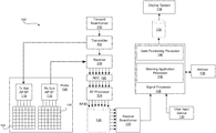
- FIG. 2 is a block diagram of an exemplary ultrasound system that is operable to automatically provide artifact warnings in Pulsed-Wave (PW) Doppler imaging, in accordance with various embodiments.
- PW Pulsed-Wave
- FIG. 3 illustrates an exemplary B-mode image having a selected gate location and a virtual gate location corresponding to a selected pulse repetition frequency (PRF), in accordance with various embodiments.
- PRF pulse repetition frequency
- FIG. 4 illustrates an exemplary B-mode image having a selected gate location and a virtual gate location positioned, based on a selected PRF, at a bright structure, in accordance with various embodiments.
- FIG. 5 illustrates an exemplary B-mode image having a selected gate location and a virtual gate location moved from the bright structure, as shown in FIG. 4 , by adjusting the PRF, in accordance with various embodiments.
- FIG. 6 illustrates an exemplary B-mode image having a selected gate location, a virtual gate location, and warnings provided along a PW line, in accordance with various embodiments.
- FIG. 7 illustrates an exemplary graph of B-mode image intensity information along a PW line of a B-mode image with respect to an intensity threshold, in accordance with various embodiments.
- FIG. 8 is a flow chart illustrating exemplary steps that may be utilized for automatically providing artifact warnings in PW Doppler imaging, in accordance with exemplary embodiments.
- Certain embodiments may be found in a method and system for automatically providing artifact warnings in Pulsed-Wave (PW) Doppler imaging.
- Various embodiments have the technical effect of providing visualization of ambiguities by providing a virtual gate along a PW line in a B-mode image at a position corresponding to a selected pulse repetition frequency (PRF).
- PRF pulse repetition frequency
- certain embodiments have the technical effect of providing a warning if a highly reflective structure is identified at a position of the virtual gate such that the virtual gate may be moved by adjusting the PRF.
- aspects of the present disclosure have the technical effect of identifying sections of the PW line having B-mode image intensity amplitudes above a threshold to guide an operator in making PRF adjustments.
- the functional blocks are not necessarily indicative of the division between hardware circuitry.
- one or more of the functional blocks e.g., processors or memories
- the programs may be stand alone programs, may be incorporated as subroutines in an operating system, may be functions in an installed software package, and the like. It should be understood that the various embodiments are not limited to the arrangements and instrumentality shown in the drawings.
- image broadly refers to both viewable images and data representing a viewable image. However, many embodiments generate (or are configured to generate) at least one viewable image.
- image is used to refer to an ultrasound mode such as B-mode (2D mode), M-mode, three-dimensional (3D) mode, CF-mode, PW Doppler, CW Doppler, MGD, and/or sub-modes of B-mode and/or CF such as Shear Wave Elasticity Imaging (SWEI), TVI, Angio, B-flow, BMI, BMI_Angio, and in some cases also MM, CM, TVD where the “image” and/or “plane” includes a single beam or multiple beams.
- SWEI Shear Wave Elasticity Imaging
- processor or processing unit refers to any type of processing unit that can carry out the required calculations needed for the various embodiments, such as single or multi-core: CPU, Accelerated Processing Unit (APU), Graphics Board, DSP, FPGA, ASIC or a combination thereof.
- CPU Accelerated Processing Unit
- GPU Graphics Board
- DSP Digital Signal processor
- FPGA Field-programmable gate array
- ASIC Application Specific integrated circuit
- various embodiments described herein that generate or form images may include processing for forming images that in some embodiments includes beamforming and in other embodiments does not include beamforming.
- an image can be formed without beamforming, such as by multiplying the matrix of demodulated data by a matrix of coefficients so that the product is the image, and wherein the process does not form any “beams”.
- forming of images may be performed using channel combinations that may originate from more than one transmit event (e.g., synthetic aperture techniques).
- ultrasound processing to form images is performed, for example, including ultrasound beamforming, such as receive beamforming, in software, firmware, hardware, or a combination thereof.
- ultrasound beamforming such as receive beamforming
- FIG. 2 One implementation of an ultrasound system having a software beamformer architecture formed in accordance with various embodiments is illustrated in FIG. 2 .
- FIG. 2 is a block diagram of an exemplary ultrasound system 100 that is operable to automatically provide artifact warnings in Pulsed-Wave (PW) Doppler imaging, in accordance with various embodiments.
- the ultrasound system 100 comprises a transmitter 102 , an ultrasound probe 104 , a transmit beamformer 110 , a receiver 118 , a receive beamformer 120 , a RF processor 124 , a RF/IQ buffer 126 , a user input device 130 , a signal processor 132 , an image buffer 136 , a display system 134 , and an archive 138 .
- the transmitter 102 may comprise suitable logic, circuitry, interfaces and/or code that may be operable to drive an ultrasound probe 104 .
- the ultrasound probe 104 may comprise a two dimensional (2D) array of piezoelectric elements.
- the ultrasound probe 104 may comprise a group of transmit transducer elements 106 and a group of receive transducer elements 108 , that normally constitute the same elements.
- the ultrasound probe 104 may be operable to acquire ultrasound image data covering at least a substantial portion of an anatomy, such as the heart, a blood vessel, or any suitable anatomical structure.
- the transmit beamformer 110 may comprise suitable logic, circuitry, interfaces and/or code that may be operable to control the transmitter 102 which, through a transmit sub-aperture beamformer 114 , drives the group of transmit transducer elements 106 to emit ultrasonic transmit signals into a region of interest (e.g., human, animal, underground cavity, physical structure and the like).
- the transmitted ultrasonic signals may be back-scattered from structures in the object of interest, like blood cells or tissue, to produce echoes.
- the echoes are received by the receive transducer elements 108 .
- the group of receive transducer elements 108 in the ultrasound probe 104 may be operable to convert the received echoes into analog signals, undergo sub-aperture beamforming by a receive sub-aperture beamformer 116 and are then communicated to a receiver 118 .
- the receiver 118 may comprise suitable logic, circuitry, interfaces and/or code that may be operable to receive the signals from the receive sub-aperture beamformer 116 .
- the analog signals may be communicated to one or more of the plurality of A/D converters 122 .
- the plurality of A/D converters 122 may comprise suitable logic, circuitry, interfaces and/or code that may be operable to convert the analog signals from the receiver 118 to corresponding digital signals.
- the plurality of A/D converters 122 are disposed between the receiver 118 and the RF processor 124 . Notwithstanding, the disclosure is not limited in this regard. Accordingly, in some embodiments, the plurality of A/D converters 122 may be integrated within the receiver 118 .
- the RF processor 124 may comprise suitable logic, circuitry, interfaces and/or code that may be operable to demodulate the digital signals output by the plurality of A/D converters 122 .
- the RF processor 124 may comprise a complex demodulator (not shown) that is operable to demodulate the digital signals to form I/Q data pairs that are representative of the corresponding echo signals.
- the RF or I/Q signal data may then be communicated to an RF/IQ buffer 126 .
- the RF/IQ buffer 126 may comprise suitable logic, circuitry, interfaces and/or code that may be operable to provide temporary storage of the RF or I/Q signal data, which is generated by the RF processor 124 .
- the receive beamformer 120 may comprise suitable logic, circuitry, interfaces and/or code that may be operable to perform digital beamforming processing to, for example, sum the delayed channel signals received from RF processor 124 via the RF/IQ buffer 126 and output a beam summed signal.
- the resulting processed information may be the beam summed signal that is output from the receive beamformer 120 and communicated to the signal processor 132 .
- the receiver 118 , the plurality of A/D converters 122 , the RF processor 124 , and the beamformer 120 may be integrated into a single beamformer, which may be digital.
- the user input device 130 may be utilized to input patient data, scan parameters, settings, select protocols and/or templates, select an examination type, select gate locations, select acquisition and/or display processing parameters, and the like.
- the user input device 130 may be operable to configure, manage and/or control operation of one or more components and/or modules in the ultrasound system 100 .
- the user input device 130 may be operable to configure, manage and/or control operation of the transmitter 102 , the ultrasound probe 104 , the transmit beamformer 110 , the receiver 118 , the receive beamformer 120 , the RF processor 124 , the RF/IQ buffer 126 , the user input device 130 , the signal processor 132 , the image buffer 136 , the display system 134 , and/or the archive 138 .
- the user input device 130 may include button(s), rotary encoder(s), a touchscreen, motion tracking, voice recognition, a mousing device, keyboard, camera and/or any other device capable of receiving a user directive.
- one or more of the user input devices 130 may be integrated into other components, such as the display system 134 , for example.
- user input device 130 may include a touchscreen display.
- an examination type and/or desired gate locations may be selected at the onset of an imaging procedure in response to a directive received via the user input device 130 .
- an ultrasound operator may identify a PW Doppler examination and a gate location via the user input device 130 .
- acquisition parameters and/or display processing parameters may be identified and applied during an imaging procedure in response to a directive received via the user input device 130 .
- the ultrasound operator may select and/or adjust, via the user input device 130 , a pulse repetition frequency for gates corresponding to blood flow anatomical structures.
- the acquisition parameters may be stored at archive 138 or any suitable data storage medium.
- the ultrasound operator may select, via the user input device 130 , a set of display parameters for gates corresponding to blood flow anatomical structures.
- the display processing parameters may include scale, gain, brightness, contrast, and the like.
- the selected display processing parameters may be stored at archive 138 or any suitable data storage medium for retrieval and application to the acquired ultrasound data.
- PW Doppler ultrasound data and/or a corresponding 2D image of a region of interest may be stored and/or retrieved in response to a directive received via the user input device 130 .
- the signal processor 132 may comprise suitable logic, circuitry, interfaces and/or code that may be operable to process ultrasound scan data (i.e., summed IQ signal) for generating ultrasound images for presentation on a display system 134 .
- the signal processor 132 is operable to perform one or more processing operations according to a plurality of selectable ultrasound modalities on the acquired ultrasound scan data.
- the signal processor 132 may be operable to perform Doppler processing, compounding, motion tracking, and/or signal processing in time and frequency domains, among other things.
- Acquired ultrasound scan data may be processed in real-time during a scanning session as the echo signals are received.
- the ultrasound scan data may be stored temporarily in the RF/IQ buffer 126 during a scanning session and processed in less than real-time in a live or off-line operation.
- the processed image data can be presented at the display system 134 and/or may be stored at the archive 138 .
- the archive 138 may be a local archive, a Picture Archiving and Communication System (PACS), or any suitable device for storing images and related information.
- the signal processor 132 may comprise a gate positioning processor 140 and a warning application processor 150 .
- the ultrasound system 100 may be operable to continuously acquire ultrasound scan data at a frame rate that is suitable for the imaging situation in question. Typical frame rates range from 20-120 but may be lower or higher.
- the acquired ultrasound scan data may be displayed on the display system 134 at a display-rate that can be the same as the frame rate, or slower or faster.
- An image buffer 136 is included for storing processed frames of acquired ultrasound scan data that are not scheduled to be displayed immediately.
- the image buffer 136 is of sufficient capacity to store at least several minutes' worth of frames of ultrasound scan data.
- the frames of ultrasound scan data are stored in a manner to facilitate retrieval thereof according to its order or time of acquisition.
- the image buffer 136 may be embodied as any known data storage medium.
- the signal processor 132 may include a gate positioning processor 140 that comprises suitable logic, circuitry, interfaces and/or code that may be operable to position a gate on the B-mode image in response to a directive from the user input device 130 .
- a gate positioning processor 140 may be configured to present a visual representation of the gate on the B-mode image and may update the PW Doppler acquisition parameters to define the depth of the selected gate.
- an operator may select and or adjust the PRF of the PW Doppler ultrasound image acquisition via the user input device 130 .
- the gate positioning processor 140 comprises suitable logic, circuitry, interfaces and/or code that may be operable to determine whether the selected PRF exceeds a threshold (i.e., high PRF mode). As an example, if the gate depth is 10 cm such that it takes 130 ⁇ s to receive the echoes from within the gate after the transmit event, the gate positioning processor 140 may determine whether the selected PRF is above 7700 Hz ( ⁇ 1/130 ⁇ s).
- the gate positioning processor 140 comprises suitable logic, circuitry, interfaces and/or code that may be operable to position a virtual gate on the B-mode image if the selected PRF exceeds the threshold such that the system is operating in the high PRF mode, which in the above example would correspond with a selected PRF exceeding a threshold of 7700 Hz.
- the gate positioning processor 140 may superimpose visual representations (e.g., icons) of the gate and/or virtual gate on the B-mode image for presentation at the display system 134 .
- the visual representation of the virtual gate may provide an operator with information regarding potential ambiguities that may arise, such as a highly reflective structure (e.g., dense tissue or an additional blood vessel) located at the position of the virtual gate, such that the operator may adjust the PRF to avoid the highly reflective structure.
- a highly reflective structure e.g., dense tissue or an additional blood vessel
- FIG. 3 illustrates an exemplary B-mode image 200 having a selected gate location 220 and a virtual gate location 222 corresponding to a selected pulse repetition frequency (PRF), in accordance with various embodiments.
- FIG. 4 illustrates an exemplary B-mode image 200 having a selected gate location 220 and a virtual gate location 222 positioned, based on a selected PRF, at a bright structure 204 , in accordance with various embodiments.
- the B-mode images 200 may include a selected gate 220 along a PW line 210 positioned over a blood vessel 202 of interest.
- the B-mode images 200 may include a virtual gate 222 positioned by the gate positioning processor 140 based on the selected PRF. Referring to FIG.
- the virtual gate 222 is located at a position of a bright structure 204 .
- a bright structure also referred to as a highly reflective structure
- an operator may adjust the PRF via the user input device 130 to move the virtual gate 222 to a position that is not at a location of a bright structure 204 .
- FIG. 5 illustrates an exemplary B-mode image 200 having a selected gate location 220 and a virtual gate location 222 moved from the bright structure 204 , as shown in FIG. 4 , by adjusting the PRF, in accordance with various embodiments.
- the B-mode image 200 may include a selected gate 220 along a PW line 210 positioned over a blood vessel 202 of interest.
- the B-mode image 200 may include a virtual gate 222 moved by the gate positioning processor 140 based on the adjusted PRF.
- the adjustment of the PRF to move the virtual gate 222 to a position that does not correspond with a bright structure 204 provides enhanced visualization of the spectrogram by reducing or eliminating artifacts that may have been present due to the bright structure 204 .
- the signal processor 132 may include a warning application processor 150 that comprises suitable logic, circuitry, interfaces and/or code that may be operable to analyze B-mode image intensity values at the virtual gate 222 to determine whether the values exceed an intensity threshold.
- a pre-defined and/or user selected image intensity threshold may correspond with image intensity values of structures expected to provide artifacts in the PW Doppler ultrasound image data.
- dense tissue 204 between an ultrasound probe 104 and the selected gate 220 may provide echoes in response to a second ultrasound transmit event that can be received at the probe 104 at a same time echoes from structure at the selected gate 220 in response to a first ultrasound transmit event are received if the virtual gate 222 is positioned at the location of the dense tissue 204 .
- the warning application processor 150 comprises suitable logic, circuitry, interfaces and/or code that may be operable to provide visual, audio, and/or physical feedback to warn an operator that the virtual gate 222 is positioned at a location of a bright structure 204 if the warning application processor 150 determines that the intensity values at the virtual gate 222 exceed the intensity threshold.
- the warning application processor 150 may present text, shapes, colorized pixels, and/or any suitable visual indicator identifying the virtual gate 222 being positioned at a location of a bright structure 204 .
- the warning application processor 150 may additionally and/or alternatively provide an audio tone, beep, warning message, and/or any suitable audio output to warn an operator that the virtual gate 222 is positioned at a location of a bright structure 204 .
- the warning application processor 150 may provide a physical warning, such as vibrations at the ultrasound probe 104 , to alert an operator that the virtual gate 222 is positioned at a location of a bright structure 204 .
- the warning application processor 150 comprises suitable logic, circuitry, interfaces and/or code that may be operable to analyze B-mode image intensity values along the PW line 210 to determine whether and/or where the values exceed an intensity threshold.
- the warning application processor 150 may present warnings at the display system 134 identifying locations along the PW line 210 that are associated with bright structures 204 .
- the operator may consult the visual feedback to provide PRF adjustments to move the virtual gate 222 to a location that is not associated with a bright structure 204 .
- the PW line warnings may be provided additionally and/or as an alternative to the virtual gate warnings described above.
- FIG. 6 illustrates an exemplary B-mode image 200 having a selected gate location 220 , a virtual gate location 222 , and warnings 230 , 232 provided along a PW line 210 , in accordance with various embodiments.
- the B-mode image 200 may include a selected gate 220 along a PW line 210 positioned over a blood vessel 202 of interest.
- the B-mode image 200 may include a virtual gate 222 positioned by the gate positioning processor 140 based on the selected PRF.
- the B-mode image 200 may include bright structures 204 that could provide artifacts in PW Doppler ultrasound image data if the virtual gate 222 is positioned at the same location as one or more of the bright structures 204 .
- the warning application processor 150 may provide a virtual gate warning 230 at the display system 134 , as shown in FIG. 6 , when the virtual gate 222 is positioned at the location of a bright structure 204 .
- the warning application processor 150 may provide PW line warnings 232 at locations along the PW line 210 where bright structures 204 are present.
- the virtual gate warning 230 alerts an operator that the PRF should be adjusted to avoid artifacts in the PW Doppler ultrasound image data.
- the PW line warnings 232 provide feedback to the operator regarding other bright structure 204 locations so that the operator may adjust the PRF to avoid the bright structure 204 locations.
- FIG. 7 illustrates an exemplary graph 300 of B-mode image intensity information along a PW line 210 of a B-mode image 200 with respect to an intensity threshold, in accordance with various embodiments.
- the graph includes image intensity values (x-axis) at various depths (y-axis) of the B-mode image data 310 along the PW line 210 .
- the graph 300 includes a B-mode ultrasound image intensity threshold 320 and warning locations 330 to provide virtual gate 230 and/or PW line warnings 232 .
- the display system 134 may be any device capable of communicating visual information to a user.
- a display system 134 may include a liquid crystal display, a light emitting diode display, and/or any suitable display or displays.
- the display system 134 can be operable to present ultrasound images and/or any suitable information.
- the ultrasound images presented at the display system 134 may include B-mode images 200 , spectrograms, PW lines 210 , selected gates 220 , virtual gates 222 , warnings 230 , 232 , and/or any suitable information.
- the archive 138 may be one or more computer-readable memories integrated with the ultrasound system 100 and/or communicatively coupled (e.g., over a network) to the ultrasound system 100 , such as a Picture Archiving and Communication System (PACS), a server, a hard disk, floppy disk, CD, CD-ROM, DVD, compact storage, flash memory, random access memory, read-only memory, electrically erasable and programmable read-only memory and/or any suitable memory.
- the archive 138 may include databases, libraries, sets of information, or other storage accessed by and/or incorporated with the signal processor 132 , for example.
- the archive 138 may be able to store data temporarily or permanently, for example.
- the archive 138 may be capable of storing medical image data, data generated by the signal processor 132 , and/or instructions readable by the signal processor 132 , among other things.
- the archive 138 stores ultrasound image data, selected gate positioning instructions, PRF threshold information and instructions, virtual gate positioning instructions, image intensity threshold information and instructions, warning instructions, for example.
- Components of the ultrasound system 100 may be implemented in software, hardware, firmware, and/or the like.
- the various components of the ultrasound system 100 may be communicatively linked.
- Components of the ultrasound system 100 may be implemented separately and/or integrated in various forms.
- the display system 134 and the user input device 130 may be integrated as a touchscreen display.
- FIG. 8 is a flow chart 400 illustrating exemplary steps 402 - 418 that may be utilized for automatically providing artifact warnings 230 , 232 in PW Doppler imaging, in accordance with exemplary embodiments.
- a flow chart 400 comprising exemplary steps 402 through 418 .
- Certain embodiments may omit one or more of the steps, and/or perform the steps in a different order than the order listed, and/or combine certain of the steps discussed below. For example, some steps may not be performed in certain embodiments. As a further example, certain steps may be performed in a different temporal order, including simultaneously, than listed below.
- a probe 104 of an ultrasound system 100 may be positioned to acquire a B-mode image 200 of a region of interest.
- the ultrasound system 100 may acquire the B-mode image 200 with an ultrasound probe 104 positioned over a region of interest, such as venous blood flow, arterial blood flow, mitral inflow, muscle tissue, and/or any suitable anatomical structures.
- a signal processor 132 of the ultrasound system 100 may receive a selection to enter a PW Doppler mode and a positioning of a gate 220 .
- the signal processor 132 may receive a selection to enter a PW Doppler mode from a user input device 130 , such as the depression of a button, a selection on a touchscreen, or any suitable user input.
- a gate positioning processor 140 of the signal processor 132 may receive a gate selection, via the user input device 130 , at a location on the B-mode image 200 at which velocity information is desired.
- the gate positioning processor 140 may be configured to superimpose a gate 220 at the selected location on the B-mode image 200 .
- the ultrasound system 100 may acquire PW Doppler signals corresponding with the position of the gate 220 and display a spectrogram.
- the ultrasound probe may acquire the PW Doppler signals corresponding with the position of the gate selected at step 404 .
- the ultrasound system 100 may process the PW Doppler signals to generate the spectrogram, which may be presented at a display system 134 .
- the signal processor 132 may determine whether a PRF adjustment is received. For example, an operator may increase a PRF to view velocity information in the spectrogram of higher velocity flows that may not be viewable at the default or initial PRF setting.
- the process 400 may continue to step 410 if a PRF adjustment is received by the signal processor 132 via the user input device 130 .
- the process 400 may end at step 418 if no PRF adjustment is received at step 408 .
- the signal processor 132 determines whether the adjusted PRF exceeds a PRF threshold. For example, the gate positioning processor 140 of the signal processor 132 may compare a PRF adjustment received at step 408 to a PRF threshold to determine whether the system is operating in a high PRF mode, which is defined as an operating mode where a time between transmit events is less than a time it takes to receive echoes from the structure at the selected gate location. The process 400 may end at step 418 if the PRF adjustment at step 408 does not result in the system 100 entering a high PRF mode. The process 400 may continue to step 412 if the PRF adjustment at step 408 results in the system 100 entering a high PRF mode.
- a PRF threshold which is defined as an operating mode where a time between transmit events is less than a time it takes to receive echoes from the structure at the selected gate location.
- the process 400 may end at step 418 if the PRF adjustment at step 408 does not result in the system 100 entering a high PRF mode.
- the process 400 may
- the signal processor 132 may determine a position of a virtual gate 222 corresponding with the PRF and present the virtual gate 222 on the B-mode image 200 .
- the gate positioning processor 150 of the signal processor 132 may determine a depth, based on the PRF selected at step 408 , that may provide echoes from a second transmit event to the ultrasound probe 104 at a same time that echoes from a first transmit event corresponding with the selected gate 220 are received by the ultrasound probe 104 .
- the gate positioning processor 150 may present a visual indicator of the virtual gate 222 overlaid on the B-mode image 200 along the PW line 210 at the determined depth.
- the signal processor 132 may analyze B-mode image intensity values at the virtual gate 222 and/or along the PW line 210 to identify the values that exceed an intensity threshold.
- a warning application processor 150 of the signal processor 132 may be configured to determine whether the intensity values of B-mode image pixels at the virtual gate 222 and/or along the PW line 210 exceed an intensity threshold that corresponds to bright structure 204 that may provide artifacts in the PW Doppler ultrasound image data.
- the signal processor 132 may provide a warning 230 at the virtual gate 222 if the intensity values exceed the intensity threshold and/or may provide a warning 230 , 232 at positions along the PW line 210 having intensity values that exceed the intensity threshold.
- the warning application processor 150 of the signal processor 132 may present text, shapes, colorized pixels, and/or any suitable visual indicator 230 at the display system 134 identifying the virtual gate 222 being positioned at a location of a bright structure 204 .
- the warning application processor 150 may present warnings 232 at the display system 134 identifying locations along the PW line 210 that are associated with bright structures 204 .
- the operator may consult the visual feedback to provide PRF adjustments to move the virtual gate 222 to a location that is not associated with a bright structure 204 .
- the process 400 may return to step 408 if additional PRF adjustments are made, for example, if the virtual gate 222 is positioned at a bright structure 204 .
- the process 400 may end at step 418 when the ultrasound procedure is finished.
- the method 400 may comprise acquiring 406 , by an ultrasound system 100 at a pulse repetition frequency (PRF), Pulsed-Wave (PW) Doppler signals from a selected gate position 220 in a high PRF mode.
- PRF pulse repetition frequency
- PW Pulsed-Wave
- the high PRF mode occurs when a first time between a first transmit event and a second transmit event is less than a second time between the first transmit event and a first receive event corresponding with the PW Doppler signals acquired from the selected gate position 220 in response to the first transmit event.
- the method 400 may comprise determining 412 , by at least one processor 132 , 140 of the ultrasound system 100 based on the PRF, a position of a virtual gate 222 along a PW line 210 in a B-mode image 200 .
- the method 400 may comprise presenting 412 , at a display system 134 , the virtual gate 222 at the determined position along the PW line 210 in the B-mode image 200 .
- the method 400 may comprise analyzing 414 , by the at least one processor 132 , 150 , B-mode image intensity values 310 at the virtual gate 222 in the B-mode image 200 to determine whether the B-mode image intensity values 310 exceed an intensity threshold 320 .
- the method 400 may comprise providing 416 , by the at least one processor 132 , 150 , a virtual gate warning 230 when the B-mode image intensity values 310 exceed the intensity threshold 320 .
- the method 400 may comprise acquiring 402 , by the ultrasound system 100 , the B-mode image 200 .
- the method 400 may comprise receiving 404 , by the at least one processor 132 , a selection to enter a PW Doppler mode from a user input device 130 .
- the method 400 may comprise receiving 404 , by the at least one processor 132 , 140 , the selected gate position 220 from the user input device 130 .
- the method 400 may comprise presenting 404 , at the display system 132 , the selected gate position 220 in the B-mode image 200 .
- the method 400 may comprise receiving 408 , by the at least one processor 132 , 140 , an adjustment to the PRF from a user input device 130 .
- the method 400 may comprise determining 410 , by the at least one processor 132 , 140 , whether the adjustment to the PRF corresponds with the high PRF mode.
- the method 400 may comprise analyzing 414 , by the at least one processor 132 , 150 , the B-mode image intensity values 310 along the PW line 210 in the B-mode image to identify the B-mode image intensity values 310 along the PW line 210 that exceed the intensity threshold 320 .
- the method 400 may comprise presenting 416 , at the display system 134 , a PW line warning 232 at positions along the PW line 210 having the B-mode image intensity values 310 that exceed the intensity threshold 320 .
- the method 400 may comprise receiving 408 , by the at least one processor 132 , 140 , an adjusted PRF from a user input device 130 in response to the virtual gate warning 230 and the PW line warning 232 .
- the PW line warning 232 is a visual indicator comprising text, at least one shape 232 , and/or colorized pixels.
- the method 400 comprises receiving 408 , by the at least one processor 132 , 140 , an adjusted PRF from a user input device 130 in response to the virtual gate warning 230 .
- the virtual gate warning 230 is a visual warning 230 , an audio warning, and/or a physical warning.
- the system 100 may comprise an ultrasound system 100 , at least one processor 132 , 140 , 150 , and a display system 134 .
- the ultrasound system 100 may be configured to acquire Pulsed-Wave (PW) Doppler signals at a pulse repetition frequency (PRF) from a selected gate position 220 in a high PRF mode.
- the high PRF mode may occur when a first time between a first transmit event and a second transmit event is less than a second time between the first transmit event and a first receive event corresponding with the PW Doppler signals acquired from the selected gate position 220 in response to the first transmit event.
- the at least one processor 132 , 140 may be configured to determine a position of a virtual gate 222 along a PW line 210 in a B-mode image 200 based on the PRF.
- the at least one processor 132 , 150 may be configured to analyze B-mode image intensity values 310 at the virtual gate 222 in the B-mode image 200 to determine whether the B-mode image intensity values 310 exceed an intensity threshold 320 .
- the at least one processor 132 , 150 may be configured to provide a virtual gate warning 230 when the B-mode image intensity values 310 exceed the intensity threshold 320 .
- the display system 134 may be configured to present the virtual gate 222 at the determined position along the PW line 210 in the B-mode image 200 .
- the ultrasound system 100 may be configured to acquire the B-mode image 200 .
- the at least one processor 132 may be configured to receive a selection to enter a PW Doppler mode from a user input device 130 .
- the at least one processor 132 , 140 may be configured to receive the selected gate position 220 from the user input device 130 .
- the display system 134 may be configured to present the selected gate position 220 in the B-mode image 210 .
- the at least one processor 132 , 140 may be configured to receive an adjustment to the PRF from a user input device 130 .
- the at least one processor 132 , 140 may be configured to determine whether the adjustment to the PRF corresponds with the high PRF mode.
- the at least one processor 132 , 150 may be configured to analyze the B-mode image intensity values 310 along the PW line 210 in the B-mode image 200 to identify the B-mode image intensity values 310 along the PW line 210 that exceed the intensity threshold 320 .
- the at least one processor 132 , 150 may be configured to present, at the display system 134 , a PW line warning 232 at positions along the PW line 210 having the B-mode image intensity values 310 that exceed the intensity threshold 320 .
- the at least one processor 132 , 140 may be configured to receive an adjusted PRF from the user input device 130 in response to the virtual gate warning 230 and the PW line warning 232 .
- the at least one processor 132 , 140 is configured to receive an adjusted PRF from a user input device 130 in response to the virtual gate warning 230 .
- the virtual gate warning 230 may be a visual warning 230 , an audio warning, and/or a physical warning.
- Certain embodiments provide a non-transitory computer readable medium having stored thereon, a computer program having at least one code section.
- the at least one code section is executable by a machine for causing the machine to perform steps 400 .
- the steps 400 may comprise receiving 406 Pulsed-Wave (PW) Doppler signals acquired at a pulse repetition frequency (PRF) from a selected gate position 220 in a high PRF mode.
- PW Pulsed-Wave
- PRF pulse repetition frequency
- the steps 400 may comprise determining 412 a position of a virtual gate 222 along a PW line 210 in a B-mode image 200 based on the PRF.
- the steps 400 may comprise presenting 412 the virtual gate 222 at the determined position along the PW line 210 in the B-mode image 200 at a display system 134 .
- the steps 400 may comprise analyzing 414 B-mode image intensity values 310 at the virtual gate 222 in the B-mode image 210 to determine whether the B-mode image intensity values 310 exceed an intensity threshold 320 .
- the steps 400 may comprise providing 416 a virtual gate warning 230 when the B-mode image intensity values 310 exceed the intensity threshold 320 .
- the steps 400 may comprise receiving 402 the B-mode image 200 .
- the steps 400 may comprise receiving 404 a selection to enter a PW Doppler mode.
- the steps 400 may comprise receiving 404 the selected gate position 220 .
- the steps 400 may comprise presenting 404 the selected gate position 220 in the B-mode image 200 at the display system 134 .
- the steps 400 may comprise analyzing 414 the B-mode image intensity values 310 along the PW line 210 in the B-mode image 200 to identify the B-mode image intensity values 310 along the PW line 210 that exceed the intensity threshold 320 .
- the steps 400 may comprise presenting 416 a PW line warning 232 at positions along the PW line 210 having the B-mode image intensity values 310 that exceed the intensity threshold 320 at the display system 134 .
- the steps 400 may comprise receiving 408 an adjusted PRF in response to the virtual gate warning 230 and the PW line warning 232 .
- the steps 400 may comprise receiving 408 an adjusted PRF in response to the virtual gate warning 230 .
- circuitry refers to physical electronic components (i.e. hardware) and any software and/or firmware (“code”) which may configure the hardware, be executed by the hardware, and or otherwise be associated with the hardware.
- code software and/or firmware
- a particular processor and memory may comprise a first “circuit” when executing a first one or more lines of code and may comprise a second “circuit” when executing a second one or more lines of code.
- and/or means any one or more of the items in the list joined by “and/or”.
- x and/or y means any element of the three-element set ⁇ (x), (y), (x, y) ⁇ .
- x, y, and/or z means any element of the seven-element set ⁇ (x), (y), (z), (x, y), (x, z), (y, z), (x, y, z) ⁇ .
- exemplary means serving as a non-limiting example, instance, or illustration.
- e.g. and “for example” set off lists of one or more non-limiting examples, instances, or illustrations.
- circuitry is “operable” to perform a function whenever the circuitry comprises the necessary hardware and code (if any is necessary) to perform the function, regardless of whether performance of the function is disabled, or not enabled, by some user-configurable setting.
- FIG. 1 may depict a computer readable device and/or a non-transitory computer readable medium, and/or a machine readable device and/or a non-transitory machine readable medium, having stored thereon, a machine code and/or a computer program having at least one code section executable by a machine and/or a computer, thereby causing the machine and/or computer to perform the steps as described herein for automatically providing artifact warnings in Pulsed-Wave (PW) Doppler imaging.
- PW Pulsed-Wave
- the present disclosure may be realized in hardware, software, or a combination of hardware and software.
- the present disclosure may be realized in a centralized fashion in at least one computer system, or in a distributed fashion where different elements are spread across several interconnected computer systems. Any kind of computer system or other apparatus adapted for carrying out the methods described herein is suited.
- Computer program in the present context means any expression, in any language, code or notation, of a set of instructions intended to cause a system having an information processing capability to perform a particular function either directly or after either or both of the following: a) conversion to another language, code or notation; b) reproduction in a different material form.
Landscapes
- Health & Medical Sciences (AREA)
- Life Sciences & Earth Sciences (AREA)
- Engineering & Computer Science (AREA)
- Physics & Mathematics (AREA)
- Remote Sensing (AREA)
- Radar, Positioning & Navigation (AREA)
- Molecular Biology (AREA)
- General Health & Medical Sciences (AREA)
- Radiology & Medical Imaging (AREA)
- Biomedical Technology (AREA)
- Heart & Thoracic Surgery (AREA)
- Medical Informatics (AREA)
- Nuclear Medicine, Radiotherapy & Molecular Imaging (AREA)
- Surgery (AREA)
- Animal Behavior & Ethology (AREA)
- Pathology (AREA)
- Public Health (AREA)
- Veterinary Medicine (AREA)
- Biophysics (AREA)
- Acoustics & Sound (AREA)
- Computer Networks & Wireless Communication (AREA)
- General Physics & Mathematics (AREA)
- Computer Vision & Pattern Recognition (AREA)
- Hematology (AREA)
- Vascular Medicine (AREA)
- Ultra Sonic Daignosis Equipment (AREA)
Priority Applications (3)
| Application Number | Priority Date | Filing Date | Title |
|---|---|---|---|
| US16/661,240 US11219430B2 (en) | 2019-10-23 | 2019-10-23 | Method and system for automatically providing artifact warnings in pulsed-wave doppler imaging |
| CN202011106080.0A CN112690826A (zh) | 2019-10-23 | 2020-10-15 | 用于在脉冲波多普勒成像中自动提供伪影警告的方法和系统 |
| JP2020175902A JP7135051B2 (ja) | 2019-10-23 | 2020-10-20 | パルス波ドップラー撮像においてアーチファクト警告を自動的に提供するための方法およびシステム |
Applications Claiming Priority (1)
| Application Number | Priority Date | Filing Date | Title |
|---|---|---|---|
| US16/661,240 US11219430B2 (en) | 2019-10-23 | 2019-10-23 | Method and system for automatically providing artifact warnings in pulsed-wave doppler imaging |
Publications (2)
| Publication Number | Publication Date |
|---|---|
| US20210121157A1 US20210121157A1 (en) | 2021-04-29 |
| US11219430B2 true US11219430B2 (en) | 2022-01-11 |
Family
ID=75506138
Family Applications (1)
| Application Number | Title | Priority Date | Filing Date |
|---|---|---|---|
| US16/661,240 Active 2040-07-09 US11219430B2 (en) | 2019-10-23 | 2019-10-23 | Method and system for automatically providing artifact warnings in pulsed-wave doppler imaging |
Country Status (3)
| Country | Link |
|---|---|
| US (1) | US11219430B2 (ja) |
| JP (1) | JP7135051B2 (ja) |
| CN (1) | CN112690826A (ja) |
Families Citing this family (1)
| Publication number | Priority date | Publication date | Assignee | Title |
|---|---|---|---|---|
| US11890132B2 (en) * | 2020-02-28 | 2024-02-06 | Fujifilm Sonosite, Inc. | Detecting fluid flows using ultrasound imaging systems |
Citations (3)
| Publication number | Priority date | Publication date | Assignee | Title |
|---|---|---|---|---|
| US6322509B1 (en) | 2000-05-01 | 2001-11-27 | Ge Medical Systems Global Technology Company, Llc | Method and apparatus for automatic setting of sample gate in pulsed doppler ultrasound imaging |
| JP2005185731A (ja) | 2003-12-26 | 2005-07-14 | Toshiba Corp | ドプラ超音波診断装置 |
| US20140018680A1 (en) | 2012-07-13 | 2014-01-16 | Siemens Medical Solutions Usa, Inc. | Automatic Doppler Gate Positioning in Spectral Doppler Ultrasound Imaging |
Family Cites Families (11)
| Publication number | Priority date | Publication date | Assignee | Title |
|---|---|---|---|---|
| JPH0249643A (ja) * | 1988-08-11 | 1990-02-20 | Toshiba Corp | 超音波診断装置 |
| US20140018880A1 (en) * | 2002-04-08 | 2014-01-16 | Medtronic Ardian Luxembourg S.A.R.L. | Methods for monopolar renal neuromodulation |
| JP2004195018A (ja) * | 2002-12-19 | 2004-07-15 | Ge Medical Systems Global Technology Co Llc | 血流速度計測装置、血流速度計測方法およびその方法をコンピュータに実行させるプログラム |
| US8469887B2 (en) * | 2003-12-19 | 2013-06-25 | General Electric Company | Method and apparatus for flow parameter imaging |
| JP4820210B2 (ja) * | 2006-05-11 | 2011-11-24 | ジーイー・メディカル・システムズ・グローバル・テクノロジー・カンパニー・エルエルシー | 超音波診断装置及び超音波診断画像生成方法 |
| CN102133107B (zh) * | 2010-01-21 | 2014-10-15 | 深圳迈瑞生物医疗电子股份有限公司 | 改进多普勒超声成像中hprf性能的方法与装置 |
| CN102551791B (zh) * | 2010-12-17 | 2016-04-27 | 深圳迈瑞生物医疗电子股份有限公司 | 一种超声成像方法和装置 |
| KR102387708B1 (ko) * | 2015-01-30 | 2022-04-19 | 삼성메디슨 주식회사 | 향상된 hprf 도플러 영상을 위한 가이드를 제공하는 방법 및 초음파 시스템 |
| US10813626B2 (en) * | 2016-06-30 | 2020-10-27 | Siemens Medical Solutions Usa, Inc. | Spectral doppler detection |
| WO2018091341A1 (en) * | 2016-11-17 | 2018-05-24 | Koninklijke Philips N.V. | Ultrasound system and method for detection of kidney stones using twinkling artifact |
| CN106859701A (zh) * | 2017-02-13 | 2017-06-20 | 深圳安盛生物医疗技术有限公司 | 一种高脉冲多普勒成像的速度标尺调节方法及装置 |
-
2019
- 2019-10-23 US US16/661,240 patent/US11219430B2/en active Active
-
2020
- 2020-10-15 CN CN202011106080.0A patent/CN112690826A/zh active Pending
- 2020-10-20 JP JP2020175902A patent/JP7135051B2/ja active Active
Patent Citations (3)
| Publication number | Priority date | Publication date | Assignee | Title |
|---|---|---|---|---|
| US6322509B1 (en) | 2000-05-01 | 2001-11-27 | Ge Medical Systems Global Technology Company, Llc | Method and apparatus for automatic setting of sample gate in pulsed doppler ultrasound imaging |
| JP2005185731A (ja) | 2003-12-26 | 2005-07-14 | Toshiba Corp | ドプラ超音波診断装置 |
| US20140018680A1 (en) | 2012-07-13 | 2014-01-16 | Siemens Medical Solutions Usa, Inc. | Automatic Doppler Gate Positioning in Spectral Doppler Ultrasound Imaging |
Also Published As
| Publication number | Publication date |
|---|---|
| JP7135051B2 (ja) | 2022-09-12 |
| CN112690826A (zh) | 2021-04-23 |
| JP2021090724A (ja) | 2021-06-17 |
| US20210121157A1 (en) | 2021-04-29 |
Similar Documents
| Publication | Publication Date | Title |
|---|---|---|
| US11903768B2 (en) | Method and system for providing ultrasound image enhancement by automatically adjusting beamformer parameters based on ultrasound image analysis | |
| US11896436B2 (en) | Method and system for providing standard ultrasound scan plane views using automatic scan acquisition rotation and view detection | |
| US20220071595A1 (en) | Method and system for adapting user interface elements based on real-time anatomical structure recognition in acquired ultrasound image views | |
| US20180140279A1 (en) | Method and system for enhanced detection and visualization of a surgical needle in ultrasound data by performing shear wave elasticity imaging | |
| US10537305B2 (en) | Detecting amniotic fluid position based on shear wave propagation | |
| US11980495B2 (en) | Method and system for providing enhanced color flow doppler and pulsed wave doppler ultrasound images by applying clinically specific flow profiles | |
| CN111345845B (zh) | 增加体积复合超声图像的有效线密度的方法和系统 | |
| US11219430B2 (en) | Method and system for automatically providing artifact warnings in pulsed-wave doppler imaging | |
| US9999405B2 (en) | Method and system for enhanced visualization of a curved structure by automatically displaying a rendered view of a curved image slice | |
| US11109841B2 (en) | Method and system for simultaneously presenting doppler signals of a multi-gated doppler signal corresponding with different anatomical structures | |
| JP7187694B2 (ja) | マルチゲートドプラ信号のパルス波ドプラ信号に基づいて解剖学的構造を経時的に追跡するための方法及びシステム | |
| US11980501B2 (en) | Method and system for providing enhanced ultrasound images simulating acquisition at high acoustic power by processing ultrasound images acquired at low acoustic power | |
| US20240111046A1 (en) | Method and system for flow processing on channel data for application of nonlinear beamforming | |
| US10299764B2 (en) | Method and system for enhanced visualization of moving structures with cross-plane ultrasound images | |
| US11974884B2 (en) | Method and system for dynamically adjusting imaging parameters during an ultrasound scan | |
| US11468573B2 (en) | Method and system for enhanced visualization of color flow ultrasound | |
| US20210390685A1 (en) | Method and system for providing clutter suppression in vessels depicted in b-mode ultrasound images | |
| US20230210498A1 (en) | Method and system for automatically setting an elevational tilt angle of a mechanically wobbling ultrasound probe | |
| US20230181166A1 (en) | Method and system for capturing and summarizing changes in ultrasound scanning settings | |
| US20240041430A1 (en) | Method and system for defining a boundary of a region of interest by applying threshold values to outputs of a probabilistic automatic segmentation model based on user-selected segmentation sensitivity levels |
Legal Events
| Date | Code | Title | Description |
|---|---|---|---|
| AS | Assignment |
Owner name: GE PRECISION HEALTHCARE LLC, WISCONSIN Free format text: ASSIGNMENT OF ASSIGNORS INTEREST;ASSIGNOR:WENZEL, TIMO;REEL/FRAME:050802/0280 Effective date: 20191023 |
|
| FEPP | Fee payment procedure |
Free format text: ENTITY STATUS SET TO UNDISCOUNTED (ORIGINAL EVENT CODE: BIG.); ENTITY STATUS OF PATENT OWNER: LARGE ENTITY |
|
| STPP | Information on status: patent application and granting procedure in general |
Free format text: DOCKETED NEW CASE - READY FOR EXAMINATION |
|
| STPP | Information on status: patent application and granting procedure in general |
Free format text: NOTICE OF ALLOWANCE MAILED -- APPLICATION RECEIVED IN OFFICE OF PUBLICATIONS |
|
| STPP | Information on status: patent application and granting procedure in general |
Free format text: PUBLICATIONS -- ISSUE FEE PAYMENT RECEIVED |
|
| STPP | Information on status: patent application and granting procedure in general |
Free format text: PUBLICATIONS -- ISSUE FEE PAYMENT VERIFIED |
|
| STCF | Information on status: patent grant |
Free format text: PATENTED CASE |