US11215705B2 - Radar device - Google Patents
Radar device Download PDFInfo
- Publication number
- US11215705B2 US11215705B2 US16/487,561 US201816487561A US11215705B2 US 11215705 B2 US11215705 B2 US 11215705B2 US 201816487561 A US201816487561 A US 201816487561A US 11215705 B2 US11215705 B2 US 11215705B2
- Authority
- US
- United States
- Prior art keywords
- frequency
- signal
- search
- unit
- modulation
- Prior art date
- Legal status (The legal status is an assumption and is not a legal conclusion. Google has not performed a legal analysis and makes no representation as to the accuracy of the status listed.)
- Expired - Fee Related, expires
Links
Images


Classifications
-
- G—PHYSICS
- G01—MEASURING; TESTING
- G01S—RADIO DIRECTION-FINDING; RADIO NAVIGATION; DETERMINING DISTANCE OR VELOCITY BY USE OF RADIO WAVES; LOCATING OR PRESENCE-DETECTING BY USE OF THE REFLECTION OR RERADIATION OF RADIO WAVES; ANALOGOUS ARRANGEMENTS USING OTHER WAVES
- G01S7/00—Details of systems according to groups G01S13/00, G01S15/00, G01S17/00
- G01S7/02—Details of systems according to groups G01S13/00, G01S15/00, G01S17/00 of systems according to group G01S13/00
- G01S7/023—Interference mitigation, e.g. reducing or avoiding non-intentional interference with other HF-transmitters, base station transmitters for mobile communication or other radar systems, e.g. using electro-magnetic interference [EMI] reduction techniques
- G01S7/0232—Avoidance by frequency multiplex
-
- G—PHYSICS
- G01—MEASURING; TESTING
- G01S—RADIO DIRECTION-FINDING; RADIO NAVIGATION; DETERMINING DISTANCE OR VELOCITY BY USE OF RADIO WAVES; LOCATING OR PRESENCE-DETECTING BY USE OF THE REFLECTION OR RERADIATION OF RADIO WAVES; ANALOGOUS ARRANGEMENTS USING OTHER WAVES
- G01S13/00—Systems using the reflection or reradiation of radio waves, e.g. radar systems; Analogous systems using reflection or reradiation of waves whose nature or wavelength is irrelevant or unspecified
- G01S13/02—Systems using reflection of radio waves, e.g. primary radar systems; Analogous systems
- G01S13/06—Systems determining position data of a target
- G01S13/08—Systems for measuring distance only
- G01S13/32—Systems for measuring distance only using transmission of continuous waves, whether amplitude-, frequency-, or phase-modulated, or unmodulated
- G01S13/34—Systems for measuring distance only using transmission of continuous waves, whether amplitude-, frequency-, or phase-modulated, or unmodulated using transmission of continuous, frequency-modulated waves while heterodyning the received signal, or a signal derived therefrom, with a locally-generated signal related to the contemporaneously transmitted signal
-
- G—PHYSICS
- G01—MEASURING; TESTING
- G01S—RADIO DIRECTION-FINDING; RADIO NAVIGATION; DETERMINING DISTANCE OR VELOCITY BY USE OF RADIO WAVES; LOCATING OR PRESENCE-DETECTING BY USE OF THE REFLECTION OR RERADIATION OF RADIO WAVES; ANALOGOUS ARRANGEMENTS USING OTHER WAVES
- G01S13/00—Systems using the reflection or reradiation of radio waves, e.g. radar systems; Analogous systems using reflection or reradiation of waves whose nature or wavelength is irrelevant or unspecified
- G01S13/88—Radar or analogous systems specially adapted for specific applications
- G01S13/93—Radar or analogous systems specially adapted for specific applications for anti-collision purposes
- G01S13/931—Radar or analogous systems specially adapted for specific applications for anti-collision purposes of land vehicles
-
- G—PHYSICS
- G01—MEASURING; TESTING
- G01S—RADIO DIRECTION-FINDING; RADIO NAVIGATION; DETERMINING DISTANCE OR VELOCITY BY USE OF RADIO WAVES; LOCATING OR PRESENCE-DETECTING BY USE OF THE REFLECTION OR RERADIATION OF RADIO WAVES; ANALOGOUS ARRANGEMENTS USING OTHER WAVES
- G01S7/00—Details of systems according to groups G01S13/00, G01S15/00, G01S17/00
- G01S7/02—Details of systems according to groups G01S13/00, G01S15/00, G01S17/00 of systems according to group G01S13/00
- G01S7/023—Interference mitigation, e.g. reducing or avoiding non-intentional interference with other HF-transmitters, base station transmitters for mobile communication or other radar systems, e.g. using electro-magnetic interference [EMI] reduction techniques
-
- G—PHYSICS
- G08—SIGNALLING
- G08G—TRAFFIC CONTROL SYSTEMS
- G08G1/00—Traffic control systems for road vehicles
- G08G1/16—Anti-collision systems
Definitions
- the present invention relates to a radar device.
- radar devices mounted on a vehicle to detect objects such as an obstacle in the surroundings are known for use in automatic driving of a vehicle and a driving assistance system.
- a radar device generally modulates a radio wave in a frequency band having excellent linearity such as millimeter wave bands (77 GHz, 79 GHz) and a quasi-millimeter wave band (24 GHz) by a modulation system such as frequency modulated continuous wave (FMCW) modulation and multi-frequency CW modulation and emits the modulated radio wave. Then a reflection wave of the emitted radio wave from a surrounding object is received and subjected to signal processing, and thereby calculation of the relative distance, velocity, and direction (angle) of the surrounding object with respect to the radar device is performed.
- FMCW frequency modulated continuous wave
- the received reflection wave is subjected to fast Fourier transform (FFT) processing to be decomposed into frequency components, and in a case where a peak value of the spectrum is larger than or equal to a prescribed signal to noise ratio (SNR), it is detected as a surrounding object. Therefore, it is necessary to reduce the noise level to increase the signal strength in order to improve the detection rate and to suppress false detection.
- FFT fast Fourier transform
- a radar device for vehicles is highly likely to receive not only the original reception signal but also a reflection wave, which is a radio wave emitted from a radar device of another vehicle and reflected by a surrounding object, or to directly receive a radio wave emitted from a radar device of another vehicle.
- a reflection wave which is a radio wave emitted from a radar device of another vehicle and reflected by a surrounding object, or to directly receive a radio wave emitted from a radar device of another vehicle.
- the host vehicle is traveling closely in parallel with or behind another vehicle or when a large number of vehicles are densely populated within a range of a few meters due to traffic congestion, or the like, there is a high probability of receiving radio wave interference from other vehicles.
- the noise level of an FFT processing result generally increases due to occurrence of disturbance in a received waveform in a case where a radar device using a modulation system such as FMCW modulation or multi-frequency CW modulation undergoes radio wave interference from another radar device using a similar modulation system.
- a modulation waveform of the radar device of the other vehicle is similar to a modulation waveform of the radar device of the host vehicle, not only the noise level increases, but it is also conceivable that a reception signal from the radar device of the other vehicle may be erroneously recognized as a surrounding object.
- PTL 1 discloses a technique of an in-vehicle radar device that changes a frequency used for transmission waves to another frequency when radio wave interference is detected.
- a prescribed frequency or a randomly selected frequency is used as the frequency of transmission waves after the change. Therefore, in a situation where a large number of radar devices having different frequencies are present around the host vehicle, radio wave interference may occur even at a frequency after the change. Since the frequency change is repeated in such a case, stable operation of the radar device cannot be achieved.
- a radar device includes: an oscillation unit which generates a frequency-modulated modulation signal; a transmission unit which emits a transmission signal frequency-modulated during a prescribed modulation operation period using the modulation signal; a reception unit which receives a reception signal which is the transmission signal reflected by a surrounding object; an object information calculation unit which calculates information of the object on the basis of the reception signal; an interference state analysis unit which measures a surrounding radio wave interference state in a range between a prescribed minimum frequency and a maximum frequency during a search modulation operation period which does not overlap with the modulation operation period; and a band selection unit which selects a frequency band of the transmission signal on the basis of the radio wave interference state measured by the interference state analysis unit.
- the present invention implements stable operation of a radar device even when there is radio wave interference among a large number of radar devices.
- FIG. 1 is a diagram illustrating a configuration of a radar device according to an embodiment of the present invention.
- FIG. 2 is a diagram illustrating a functional configuration of a signal processing unit according to an embodiment of the present invention.
- FIG. 3 is a flowchart of processing executed by the signal processing unit according to an embodiment of the present invention.
- FIG. 4 includes graphs illustrating examples of a modulation signal.
- FIG. 5 includes graphs illustrating an example of a search modulation signal and a search reception signal.
- FIG. 6 includes graphs illustrating an example of a search modulation signal and a search reception signal.
- FIG. 7 includes graphs illustrating an example of a search modulation signal and a search reception signal.
- FIG. 8 is a flowchart of frequency search processing in the first embodiment of the present invention.
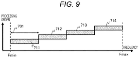
- FIG. 9 is a graph illustrating an example of frequency bands of units of processing and a processing order in the frequency search processing.
- FIG. 10 is a graph illustrating an example of frequency bands of units of processing and a processing order in the frequency search processing.
- FIG. 11 is a graph illustrating an example of frequency bands of units of processing and a processing order in the frequency search processing.
- FIG. 12 includes graphs illustrating examples of an FFT processing result and a noise level of a search reception signal.
- FIG. 13 includes flowcharts of band selection processing.
- FIG. 14 includes graphs explaining the overall operation of the radar device.
- FIG. 15 is a flowchart of frequency search processing in a second embodiment of the present invention.
- FIG. 1 is a diagram illustrating a configuration of a radar device 108 according to an embodiment of the present invention.
- the radar device 108 is mounted on a vehicle such as an automobile to detect an object around the vehicle and is used to measure a radio wave interference state around the vehicle.
- the radar device 108 includes a transmission antenna 101 , a reception antenna 102 , a transmission unit 103 , a reception unit 104 , an oscillator 105 , a signal processing unit 106 , and a communication interface 107 .
- the radar device 108 is connected to a vehicle control device 109 provided in the vehicle.
- the oscillator 105 generates a frequency-modulated modulation signal and supplies the modulation signal to the transmission unit 103 and the reception unit 104 .
- the oscillator 105 for example, a phase locked loop (PLL) including a voltage controlled oscillator (VCO), a multiplier, and the like is used.
- the frequency of the modulation signal output from the oscillator 105 or a frequency obtained by dividing the frequency of the modulation signal by a prescribed ratio is controlled (modulated) by the signal processing unit 106 .
- the oscillator 105 generates a modulation signal by different methods for detecting an object around the vehicle and for measuring a radio wave interference state around the vehicle. This point will be described later in detail.
- the transmission unit 103 For detection of an object around the vehicle, the transmission unit 103 outputs a frequency-modulated transmission signal to the transmission antenna 101 by power-amplifying the modulation signal from the oscillator 105 .
- This transmission signal is emitted via the transmission antenna 101 as a radio wave directed to the surroundings of the vehicle, for example, ahead of the vehicle.
- a period during which a frequency-modulated transmission signal is emitted from the transmission antenna 101 is referred to as a “modulation operation period.”
- the transmission unit 103 does not emit a transmission signal when measuring a radio wave interference state around the vehicle. At this time, the operation of the transmission unit 103 may be halted, or the oscillator 105 may not output the modulation signal to the transmission unit 103 .
- the reception unit 104 receives a signal obtained when the transmission signal emitted from the transmission unit 103 via the transmission antenna 101 during the modulation operation period is reflected by an object around the vehicle and input to the reception antenna 102 .
- a signal received by the reception unit 104 in response to a transmission signal from the transmission unit 103 in the above manner is referred to as a “reception signal.”
- the reception signal is mixed with the modulation signal from the oscillator 105 , and a beat signal corresponding to the frequency difference of these signals is generated to perform frequency down conversion.
- the beat signal generated by the reception unit 104 is input to the signal processing unit 106 after unnecessary frequencies are cut off through a band limiting filter (not illustrated).
- the signal processing unit 106 For detection of an object around the vehicle, the signal processing unit 106 causes the oscillator 105 to generate the modulation signal for the transmission unit 103 to emit a transmission signal during the modulation operation period. Then, digital data obtained by AD-converting the beat signal from the reception unit 104 is input, and signal processing for detecting an object around the vehicle is performed on the basis of the digital data.
- a period during which the signal processing unit 106 performs such signal processing is referred to as a “signal processing period.”
- the signal processing unit 106 causes the oscillator 105 to generate a modulation signal for measuring a radio wave interference state around the vehicle and searching for a frequency band having less interference by a method different from the modulation signal used by the transmission unit 103 to emit the transmission signal. Then, the radio wave interference state around the vehicle is measured on the basis of a signal received by the reception unit 104 using this modulation signal, and a frequency band of a subsequent transmission signal is selected.
- the reception unit 104 mixes the signal input via the reception antenna 102 with the modulation signal from the oscillator 105 like when receiving a reception signal to generate a beat signal corresponding to the frequency difference between these signals, and outputs the beat signal to the signal processing unit 106 through the band limiting filter (not illustrated).
- the signal processing unit 106 receives input of digital data obtained by AD-converting the beat signal from the reception unit 104 and performs signal processing for measurement of a radio wave interference state and selection of a frequency band on the basis of the digital data.
- a modulation signal generated by the oscillator 105 at this time is referred to as a “search modulation signal,” and a signal received by the reception unit 104 is referred to as a “search reception signal.”
- a period during which the oscillator 105 generates a search modulation signal is referred to as a “search modulation operation period,” and a period during which the signal processing unit 106 performs the above signal processing is referred to as a “frequency search processing period.”
- a set of the modulation operation period, the signal processing period, the search modulation operation period, and the frequency search processing period (hereinafter, referred to as a “frame”) is repeated at constant periods.
- the modulation operation period and the signal processing period may be separate periods which do not overlap each other in the same frame, or may overlap partially or entirely.
- the search modulation operation period and the frequency search processing period as well as the signal processing period and the search modulation operation period may be separate periods which do not overlap each other in the same frame, or may overlap partially or entirely.
- the frequency search processing period and the modulation operation period may overlap partially or entirely over two consecutive frames. As long as the modulation operation period and the search modulation operation period do not overlap, the above periods can be set in any manner.
- the communication interface 107 performs interface processing of communication signals input or output between the radar device 108 and the vehicle control device 109 .
- the interface processing performed by the communication interface 107 allows a signal processing result of the signal processing unit 106 to be transmitted to the vehicle control device 109 and various types of control data transmitted from the vehicle control device 109 to be input to the signal processing unit 106 .
- FIG. 2 is a diagram illustrating a functional configuration of the signal processing unit 106 according to an embodiment of the present invention.
- the signal processing unit 106 includes an FFT processing unit 110 , a demultiplexer 111 , an object information calculation unit 112 , an interference state analysis unit 113 , a band selection unit 114 , and a search modulation control unit 115 as its functions.
- the signal processing unit 106 includes, for example, a CPU, a ROM, a RAM, and the like, and implements these functions by executing a program stored in the ROM by the CPU. Note that the respective functions of the signal processing unit 106 may be implemented by hardware such as an FPGA.
- the FFT processing unit 110 receives input of the digital data of the beat signal output from the reception unit 104 and AD converted.
- the FFT processing unit 110 performs fast Fourier transform (FFT) on the basis of the digital data of the input beat signal to obtain a signal waveform in which the beat signal is decomposed into frequency components.
- Information of the signal waveform obtained by the FFT processing unit 110 is output to the object information calculation unit 112 or the interference state analysis unit 113 via the demultiplexer 111 .
- the demultiplexer 111 switches an output destination of signal strength information for each frequency component obtained by the FFT processing unit 110 depending on the operation state of the signal processing unit 106 . Specifically, in the signal processing period during which the signal processing unit 106 performs signal processing for detection of an object around the vehicle, an output destination of the demultiplexer 111 is switched such that spectrum information of the reception signal obtained by the FFT processing unit 110 is output to the object information calculation unit 112 .
- an output destination of the demultiplexer 111 is switched such that spectrum information of the search reception signal obtained by the FFT processing unit 110 is output the interference state analysis unit 113 .
- the object information calculation unit 112 detects an object around the vehicle on the basis of the spectrum information of the reception signal output from the FFT processing unit 110 and calculates object information. Specifically, the frequency of a signal representing an object around the vehicle is identified from the spectrum information of the reception signal, and angle estimation processing, tracking processing, etc. are performed to calculate object information representing the relative distance, velocity, angle, and the like of the object with respect to the radar device 108 .
- the object information calculated by the object information calculation unit 112 is transmitted to the vehicle control device 109 via the communication interface 107 .
- the interference state analysis unit 113 measures the radio wave interference state around the vehicle on the basis of the spectrum information of the search reception signal output from the FFT processing unit 110 . Specifically, the radio wave interference state around the vehicle is measured by measuring the noise level of the search reception signal for each prescribed frequency band on the basis of the spectrum information of the search reception signal. The measurement result of the radio wave interference state by the interference state analysis unit 113 is output to the band selection unit 114 .
- the band selection unit 114 selects the frequency band of the transmission signal on the basis of the measurement result of the radio wave interference state output from the interference state analysis unit 113 . Specifically, a frequency band with a small noise level in the measurement result of the radio wave interference state is searched as a frequency band with less interference, and the frequency band is selected as the frequency band of a subsequent transmission signal. Then, a control signal corresponding to the selected frequency band is output to the oscillator 105 to be used for frequency control of a modulation signal in modulation operation periods in the subsequent frames.
- the search modulation control unit 115 controls the oscillator 105 in the search modulation operation period. Specifically, the oscillator 105 is controlled to generate a search modulation signal by output of a control signal corresponding to a prescribed search modulation signal to the oscillator 105 during the search modulation operation period.
- the search modulation signal is a modulation signal obtained by a frequency sweep between a prescribed minimum frequency and a maximum frequency within a frequency range available to the radar device 108 , which will be described later in detail.
- the configuration of the radar device 108 described with reference to FIG. 1 and the functional configuration of the signal processing unit 106 described with reference to FIG. 2 are merely examples.
- the contents of the present invention are not limited to these configurations but are generally applicable to radar devices having other configurations.
- a plurality of transmission antennas 101 and a plurality of reception antennas 102 may be included, and the FFT processing unit 110 may be implemented by separate hardware other than the signal processing unit 106 .
- FIG. 3 is a flowchart of processing performed by the signal processing unit 106 according to an embodiment of the present invention.
- the signal processing unit 106 implements the processing illustrated in the flowchart of FIG. 3 by, for example, a program executed by the CPU.
- step S 110 the signal processing unit 106 performs initial setting of various parameters in the radar device 108 .
- initial values are set such as a modulation setting parameter for a modulation signal generated by the oscillator 105 in a modulation operation period, a signal processing setting parameter for signal processing executed by the signal processing unit 106 in a signal processing period, a search setting parameter for a search modulation signal generated by the oscillator 105 in a search modulation operation period, and a search processing setting parameter for signal processing performed by the signal processing unit 106 in a frequency search processing period.
- the initial values of these parameters those previously stored in the radar device 108 may be used, or values used immediately before may be used.
- step S 120 the signal processing unit 106 controls the oscillator 105 and the transmission unit 103 to emit a frequency-modulated transmission signal from the transmission antenna 101 toward the surroundings of the vehicle. At this time, the signal processing unit 106 controls the frequency of the modulation signal generated by the oscillator 105 using the modulation setting parameter initialized in step S 110 and determines the frequency band of the transmission signal.
- FIG. 4 includes graphs illustrating examples of a modulation signal generated by the oscillator 105 in step S 120 of FIG. 3 .
- FIG. 4( a ) is an example of two-frequency CW modulation in which a modulation signal of a frequency Fm_min and a modulation signal of a frequency Fm_max are repeatedly output at a constant period.
- FIGS. 4( b ), 4( c ) , and 4 ( d ) are examples of FMCW modulation in which the frequency is continuously changed within a prescribed range and the modulation signal is output.
- FIG. 4( b ) illustrates an example in which a modulation signal, the frequency of which is continuously increased from the frequency Fm_min to the frequency Fm_max, is repeatedly output at each period Tperiod.
- FIG. 4( c ) illustrates an example in which a modulation signal, the frequency of which is continuously increased from the frequency Fm_min to the frequency Fm_max and then reversely reduced continuously from the frequency Fm_max to the frequency Fm_min, is repeatedly output at each period Tperiod.
- FIG. 4( d ) illustrates an example in which the waveform of the modulation signal is changed halfway.
- a modulation signal the frequency of which is continuously increased from a frequency Fm2_min to a frequency Fm2_max and then continuously reduced from the frequency Fm2_max to the frequency Fm2_min, is repeatedly output for each period Tperiod1.
- a modulation signal the frequency of which is continuously increased from a frequency Fm1_min to a frequency Fm1_max, is repeatedly output at each period Tperiod2.
- the signal processing unit 106 causes the oscillator 105 to generate a modulation signal as illustrated in FIG. 4 by controlling the oscillator 105 on the basis of the modulation setting parameter.
- the modulation signal is not limited to those illustrated in FIG. 4 , and modulation signals of various waveforms other than these can be generated from the oscillator 105 .
- the signal processing unit 106 performs signal processing for detecting an object around the vehicle using digital data of a beat signal output from the reception unit 104 in response to the reception signal which is the transmission signal emitted in step S 120 and reflected by the object around the vehicle.
- the signal processing unit 106 first performs FFT processing in the FFT processing unit 110 to acquire spectrum information of the reception signal.
- the object information calculation unit 112 detects an object around the vehicle from the spectrum information of the reception signal using the signal processing setting parameter initialized in step S 110 , and calculates the relative distance, velocity, angle, and the like of the object as object information.
- step S 140 the signal processing unit 106 transmits the object information calculated in step S 120 to the vehicle control device 109 via the communication interface 107 .
- step S 150 the signal processing unit 106 performs search modulation operation of controlling the oscillator 105 to generate a search modulation signal.
- the signal processing unit 106 controls, by the search modulation control unit 115 , the frequency of the search modulation signal generated by the oscillator 105 using the search setting parameters initialized in step S 110 .
- the search modulation signal generated accordingly by the oscillator 105 is used in the reception unit 104 for reception of the search reception signal.
- FIGS. 5, 6, and 7 are graphs illustrating examples of a search modulation signal generated by the oscillator 105 in step S 150 of FIG. 3 and a search reception signal received thereby.
- FIG. 5 illustrates an example of a search modulation signal obtained by a continuous frequency sweep between a prescribed minimum frequency Fmin and a prescribed maximum frequency Fmax and a search reception signal received on the basis of the search modulation signal.
- a search reception signal corresponding to the search modulation signal is received by the reception unit 104 in the search modulation operation period 501 and then input to the signal processing unit 106 after being subjected to AD conversion.
- the above-described minimum frequency Fmin and the maximum frequency Fmax can be selected desirably from frequency bands available to the radar device 108 .
- the lower limit value and the upper limit value of frequency bands limited by the regulations of the Radio Act or the like may be set as the minimum frequency Fmin and the maximum frequency Fmax, respectively.
- the minimum frequency Fmin and the maximum frequency Fmax may be set under the limitation.
- the modulation slope of the search modulation signal can be desirably selected, and a negative slope may be selected.
- the modulation slope of the modulation signal generated by the oscillator 105 is caused to coincide with the modulation slope of the search modulation signal in step S 120 .
- this is preferable since a search reception signal having a similar tendency to the noise included in the reception signal can be acquired.
- the modulation slope of the search modulation signal may be sharpened to shorten the search modulation operation period.
- the frequency sweep may be performed in multiple stages. That is, frequency bands available to the radar device 108 may be divided into a plurality of frequency bands, and the oscillator 105 may be caused to generate a search modulation signal obtained by a frequency sweep of each of the divided frequency bands.
- the search modulation operation period is also divided into a plurality of portions on the basis of the sweep time of each of the frequency bands having been divided.
- FIG. 6 illustrates an example of a search modulation signal obtained by a frequency sweep in two stages and a search reception signal received on the basis of the search modulation signal.
- a frequency band change period 602 for the oscillator 105 is provided between a search modulation operation period 601 in the first half and a search modulation operation period 603 in the second half.
- Data of the search reception signal obtained in each of the search modulation operation periods 601 and 603 can be linked and used as continuous data when the surrounding environment does not change. Note that actually the continuity of a signal component related to an object is lost as the relative velocity between the vehicle and the surrounding object increases; however, it can be deemed that there is almost no influence from the viewpoint of searching for a noise level.
- FIG. 7 illustrates an example of a search modulation signal obtained by overlapping a part of frequency bands in which a frequency sweep is performed in two stages and a search reception signal received on the basis of the search modulation signal.
- overlapping periods 604 and 605 in which frequency bands overlap each other are included in a search modulation operation period 601 in the first half and a search modulation operation period 603 in the second half.
- the search reception signal obtained in the overlapping period 604 and the search reception signal obtained in the overlapping period 605 theoretically have the same noise characteristics in a case where the surrounding environment does not change. Therefore, in the subsequent step S 160 of FIG. 3 , it suffices to obtain the noise level using either one of the search reception signals.
- a frequency sweep may be performed in any number of stages more than two stages.
- a frequency sweep may be performed discretely instead of the frequency sweep over the entire range between the minimum frequency Fmin and the maximum frequency Fmax.
- a plurality of frequencies (or frequency bands) are set in advance between the minimum frequency Fmin and the maximum frequency Fmax, and the oscillator 105 is caused to generate a search modulation signal obtained by discrete frequency transmission at each of the frequencies (or frequency bands). This allows the search modulation operation period to be shortened.
- step S 160 the signal processing unit 106 executes frequency search processing which is signal processing for searching for a frequency band having less interference through measurement of the surrounding radio wave interference state based on the digital data of the beat signal output from the reception unit 104 on the basis of the search reception signal received in the search modulation operation in step S 150 and input to the signal processing unit 106 .
- frequency search processing is performed according to the procedure illustrated in FIG. 8 using the search processing setting parameter initially set in step S 110 .
- FIG. 8 is a flowchart of the frequency search processing performed by the signal processing unit 106 in step S 160 of FIG. 3 in the first embodiment of the present invention.
- the signal processing unit 106 causes the FFT processing unit 110 to perform FFT processing on the digital data of the beat signal input on the basis of the search reception signal for each prescribed frequency band. In this manner, spectrum information of the search reception signal for each prescribed frequency band is acquired.
- the signal processing unit 106 causes the interference state analysis unit 113 to calculate the noise level for each prescribed frequency band on the basis of the spectrum information of the search reception signal obtained in step S 161 .
- step S 163 the signal processing unit 106 determines whether calculation of noise levels in all frequency bands available to the radar device 108 has been completed. If it is determined in the above result that the calculation of noise levels in all frequency bands has been completed, the flow proceeds to step S 164 , and if it is determined that there is a frequency band for which the noise level has not been calculated yet, the flow returns to step S 161 to continue the frequency search processing.
- step S 164 the signal processing unit 106 causes the band selection unit 114 to perform band selection processing for selecting a frequency band of a transmission signal on the basis of the noise level of each of the frequency bands calculated in step S 163 . Note that details of the band selection processing will be described later with reference to FIG. 13 . After execution of the band selection processing of step S 164 , the signal processing unit 106 completes the frequency search processing by completing the flowchart illustrated in FIG. 8 .
- FIGS. 9, 10 and 11 are graphs illustrating examples of frequency bands as units of processing in the frequency search processing illustrated in FIG. 8 and the processing order thereof.
- FIG. 9 illustrates that a range between the minimum frequency Fmin and the maximum frequency Fmax of the search reception signal is divided into four frequency bands 711 , 712 , 713 , and 714 each having a frequency width 701 corresponding to the modulation width of the transmission signal and that FFT processing and noise level calculation are performed in time-series order using each of these frequency bands as a unit of processing in the frequency search processing.
- the noise level of the search reception signal is calculated for each of the frequency bands 711 to 714 , and measurement of a radio wave interference state is performed.
- the processing order of the frequency bands 711 to 714 is not limited to that illustrated in FIG. 9 and may be any order.
- FIG. 10 illustrates an example in which a frequency band as a unit of processing in the frequency search processing is changed for each processing.
- frequency bands 715 , 716 , and 717 having the same frequency width 701 as that of the frequency bands 711 to 714 are set from the frequency, shifted from the minimum frequency Fmin by a prescribed offset frequency 702 , as a starting point. Then, using these frequency bands as units of processing in the frequency search processing, FFT processing and noise level calculation are performed in time-series order.
- the offset frequency 702 can be any value as long as the frequency width of the frequency bands 711 to 714 is not exceeded.
- frequency bands 718 , 719 , and 720 are further set from the frequency, shifted from the minimum frequency Fmin by an offset frequency 703 which is different from the above offset frequency 702 , as a starting point. Then, using these frequency bands as units of processing in the frequency search processing, FFT processing and noise level calculation are performed in time-series order. By changing the offset frequency and executing the frequency search processing for each unit of processing multiple times, the noise level of the search reception signal can be calculated in finer ranges, which allows a frequency band with less interference to be found.
- the noise level of the search reception signal may be calculated in fine ranges by allowing the frequency bands as units of processing in the frequency search processing to overlap.
- FIG. 11 illustrates an example in which frequency bands as units of processing in the frequency search processing overlap.
- FFT processing and noise level calculation are performed in time-series order by allowing a plurality of frequency bands 711 to be each shifted by an offset frequency 702 and to overlap with each other in the range between the minimum frequency Fmin and the maximum frequency Fmax and using each of these frequency bands as a unit of processing in the frequency search processing.
- a noise level may be calculated by setting fine processing frequency bands as units of processing by the setting method described in FIG. 11 . In this manner, a frequency band having less interference can be found more accurately.
- FIG. 12 includes graphs illustrating examples of an FFT processing result and a noise level of a search reception signal obtained using the frequency bands 711 to 714 described in FIGS. 9 and 10 as units of processing.
- the waveforms illustrated in (a), (b), (c), and (d) correspond to the frequency bands 711 , 712 , 713 , and 714 , respectively.
- a thin line represents the spectrum of the search reception signal obtained from the FFT processing result
- a bold line represents the noise level calculated from the FFT processing result. Note that the calculation of the noise level is performed by calculating an average value or a moving average obtained by removing the peak from the spectrum of the search reception signal.
- a low and middle wave region 805 illustrated in FIG. 12( a ) may be excluded from the calculation target in each of the spectrums of the frequency bands 711 to 714 in consideration of the influence of 1/f noise generated by various circuits in the radar device 108 , and an average value of a high frequency region 806 may be calculated as the noise level.
- FIG. 12( a ) peaks 801 to 803 are detected in the spectrum of the search reception signal.
- FIG. 12( b ) differences as compared with FIG. 12( a ) are that the noise level has risen and that the peak 802 has disappeared.
- a rise portion 804 of the noise floor is identified in FIG. 12( c ) .
- FIG. 12( d ) the spectrum of the search reception signal has a similar tendency to that of FIG. 12( b ) ; however, a difference is that the noise level is generally lower as compared with that in FIG. 12( b ) .
- FIG. 13 includes flowcharts of band selection processing executed in step S 164 of FIG. 8 .
- the band selection unit 114 can select a frequency band of a transmission signal by executing, for example, one of the flowcharts illustrated in FIGS. 13( a ), 13( b ), and 13( c ) on the basis of the noise levels of the respective frequency bands calculated in step S 163 as the band selection processing.
- step S 163 the noise levels of the respective frequency bands calculated in step S 163 are sorted in the order of magnitude in step S 171 .
- step S 172 A a frequency band with the lowest noise level sorted in step S 171 , that is, a frequency band with the least interference, is selected as the frequency band of the transmission signal in the next frame.
- step S 172 A After the frequency band is selected in step S 172 A, the selection result is temporarily stored in the signal processing unit 106 , and the band selection processing is completed.
- step S 172 B any one of frequency bands up to an N-th (N is any natural number larger than or equal to 2) place in ascending order of noise levels sorted in step S 171 is selected as the frequency band of the transmission signal in the next frame.
- N is any natural number larger than or equal to 2
- the selection result is temporarily stored in the signal processing unit 106 , and the band selection processing is completed.
- step S 172 C any one of frequency bands having a noise level at a prescribed acceptable level or lower levels sorted in step S 171 is selected as the frequency band of the transmission signal in the next frame.
- the selection result is temporarily stored in the signal processing unit 106 , and the band selection processing is completed.
- band selection processing may be performed by any method.
- step S 170 the signal processing unit 106 determines whether the frequency band of the transmission signal determined by the frequency search processing of step S 160 , that is, the result of the band selection processing in step S 164 of FIG. 8 is different from the frequency band currently in use. If they are different, the flow proceeds to step S 180 . If they are the same, the flow proceeds to step S 190 without executing step S 180 .
- step S 180 the signal processing unit 106 changes the setting of the frequency band of the transmission signal of the next frame.
- the modulation setting parameter depending on the frequency of the transmission signal selected in the frequency search processing of step S 160 , the frequency of the modulation signal generated by the oscillator 105 is allow to change when the processing of step S 120 is executed again.
- step S 190 the signal processing unit 106 determines whether the operation of the radar device 108 is completed. If the radar device 108 is in operation, the flow returns to step S 120 , and the above processing is repeated. At this time, if setting of the frequency band is changed in step S 180 which has been performed immediately before, a transmission signal modulated in the frequency band after the change is emitted in step S 120 . On the other hand, if the operation of the radar device 108 is completed, the signal processing unit 106 terminates the processing illustrated in the flowchart of FIG. 3 and stops.
- FIG. 14 includes graphs explaining the overall operation of the radar device 108 by the above-described processing.
- FIG. 14( a ) illustrates an example of frequency changes of a modulation signal generated by the oscillator 105
- FIG. 14( b ) illustrates an example of a reception signal waveform input from the reception unit 104 to the signal processing unit 106 .
- the modulation signal continuously changes between a frequency Fm1_min and a frequency Fm1_max by FMCW modulation in a modulation operation period 901 , and a reception signal with relatively high noise is obtained.
- a subsequent signal processing period 902 no modulation signal is output, and thus no reception signal is obtained.
- a modulation signal which continuously changes from the frequency Fmin to the frequency Fmax is output as a search modulation signal over the entire frequency bands available to the radar device 108 , and a search reception signal corresponding thereto is input.
- the above-described processing is performed in a frequency search processing period 904 on the basis of the search reception signal obtained in the search modulation operation period 903 , and a frequency band with less interference is thereby selected.
- the modulation signal changes continuously between a frequency Fm2_min and a frequency Fm2_max, which are different from the frequency bands in the previous modulation operation period 901 , and a reception signal with suppressed noise is obtained.
- the radar device 108 includes: the oscillator 105 which generates a frequency-modulated modulation signal; the transmission unit 103 which emits a transmission signal frequency-modulation during a prescribed modulation operation period using the modulation signal generated by the oscillator 105 ; the reception unit 104 which receives a reception signal which is the transmission signal reflected by a surrounding object; and the signal processing unit 106 .
- the signal processing unit 106 includes: the object information calculation unit 112 which calculates information of the object on the basis of the reception signal; the interference state analysis unit 113 which measures a surrounding radio wave interference state in a range between a prescribed minimum frequency Fmin to a maximum frequency Fmax during a search modulation operation period that does not overlap with the modulation operation period; and the band selection unit 114 which selects a frequency band of a transmission signal on the basis of the radio wave interference state measured by the interference state analysis unit 113 .
- the object information calculation unit 112 which calculates information of the object on the basis of the reception signal
- the interference state analysis unit 113 which measures a surrounding radio wave interference state in a range between a prescribed minimum frequency Fmin to a maximum frequency Fmax during a search modulation operation period that does not overlap with the modulation operation period
- the band selection unit 114 which selects a frequency band of a transmission signal on the basis of the radio wave interference state measured by the interference state analysis unit 113 .
- the radar device 108 further includes the search modulation control unit 115 which causes the oscillator 105 to generate a search modulation signal obtained by a frequency sweep between the minimum frequency Fmin and the maximum frequency Fmax during a search modulation operation period.
- the interference state analysis unit 113 measures a radio wave interference state on the basis of a search reception signal received by the reception unit 104 using the search modulation signal. Specifically, the noise level of the search reception signal is measured for each of a plurality of frequency bands having a prescribed frequency width between the minimum frequency Fmin and the maximum frequency Fmax (steps S 161 and S 162 in FIG. 8 ).
- the band selection unit 114 selects a frequency band of a transmission signal on the basis of the measurement result of the noise level by the interference state analysis unit 113 (step S 164 ).
- the interference state analysis unit 113 can measure the radio wave interference state by using the oscillator 105 that generates a modulation signal for generating a transmission signal.
- the band selection unit 114 can select a frequency band having the lowest noise level among the plurality of frequency bands as the frequency band of the transmission signal ( FIG. 13( a ) ).
- any one of the plurality of frequency bands can be selected as the frequency band of the transmission signal in a prescribed order in an ascending order of the noise level ( FIG. 13( b ) ).
- any one of the plurality of frequency bands having the noise level at a prescribed acceptable level or a lower level may be selected as the frequency band of the transmission signal ( FIG. 13( c ) ).
- Adopting any of the above allows a frequency band with relatively low interference to be selected as the frequency band of the transmission signal.
- the interference state analysis unit 113 may execute, in time series, first analysis processing of calculating the noise level for each of the plurality of frequency bands 711 to 714 set from the prescribed minimum frequency Fmin as a starting point and second analysis processing of calculating the noise level for each of the plurality of frequency bands 715 to 717 set from the frequency, obtained by adding the prescribed offset frequency 702 to the minimum frequency Fmin, as a starting point. This can increase the likelihood of finding a frequency band with less interference.
- the interference state analysis unit 113 may execute the second analysis processing described above multiple times by further changing the offset frequency 702 to obtain the offset frequency 703 and calculating the noise level for each of the plurality of frequency bands 718 to 720 set from the frequency, obtained by adding this offset frequency 703 to the minimum frequency Fmin, as a starting point. This can further increase the likelihood of finding a frequency band with less interference.
- the interference state analysis unit 113 may cause two frequency bands 711 adjacent to each other among the plurality of frequency bands 711 , for which the noise level is to be calculated, to overlap at least partially. This can also increase the likelihood of finding a frequency band with less interference.
- the search modulation control unit 115 can cause the oscillator 105 to generate a search modulation signal obtained by a continuous frequency sweep between the minimum frequency Fmin and the maximum frequency Fmax as described in FIG. 5 .
- the range between the minimum frequency Fmin and the maximum frequency Fmax may be divided into a plurality of frequency bands, and the oscillator 105 may be caused to generate a search modulation signal obtained by a frequency sweep of each of the divided frequency bands.
- the oscillator 105 may be caused to generate a search modulation signal obtained by a discrete frequency sweep at each of a plurality of frequencies preset between the minimum frequency Fmin and the maximum frequency Fmax. Adopting any of the above allows a search modulation signal obtained by a frequency sweep within a desired search modulation operation period to be obtained in consideration of constraints due to the performance of the oscillator 105 and the like.
- FIG. 15 is a flowchart of frequency search processing performed by the signal processing unit 106 in step S 160 of FIG. 3 in the second embodiment of the present invention.
- the present embodiment differs from the first embodiment described in FIG. 8 in that the processing of steps S 162 A and S 162 B is performed after step S 162 .
- step S 162 A the signal processing unit 106 determines whether a noise level calculated in step S 162 is lower than or equal to a prescribed acceptable level. This acceptable level may be the same as or different from the acceptable level in step S 172 C of FIG. 13( c ) described in the first embodiment. If the noise level is lower than or equal to the acceptable level in the above result, the flow proceeds to step S 162 B, and a band selection unit 114 selects the frequency band for which the noise level has been calculated as the frequency band of the transmission signal in the next frame. After the frequency band is selected in step S 162 B, the selection result is temporarily stored in a signal processing unit 106 , and the band selection processing is completed. On the other hand, if the noise level is larger than the acceptable level, the flow proceeds to step S 163 , and similar processing to that described in the first embodiment is performed.
- band selection processing of step S 164 is performed in the present embodiment, it is preferable that the band selection processing is performed in accordance with the flowchart of FIG. 13( a ) or 13 ( b ) out of the flowcharts of FIGS. 13( a ), 13( b ), and 13( c ) described in the first embodiment. That is, the band selection processing of step S 164 is performed in the present embodiment when the noise level is larger than the acceptable level in all frequency bands. Therefore, in order to select a frequency band with a noise level as low as possible, it is preferable to perform the band selection processing according to the flowchart of FIG. 13( a ) or 13 ( b ).
- step S 161 in the present embodiment it is preferable to first perform FFT processing for the frequency band of the current transmission signal. That is, in the present embodiment, in a case where the noise level of a certain frequency band is lower than or equal to the acceptable level, the current frequency band is selected as the frequency band of the transmission signal without measurement of the noise level of other frequency bands. Therefore, by performing FFT processing from the frequency band of the current transmission signal to measure the noise level, the frequency band can be continuously selected when no interference is occurring in the frequency band of the current transmission signal.
- the band selection unit 114 selects that frequency band as the frequency band of the transmission signal (step S 162 B).
- step S 163 if there is no frequency band having the noise level lower than or equal to the acceptable level (step S 163 : No), a frequency band having the lowest noise level is selected as the frequency band of the transmission signal, or any frequency band is selected as the frequency band of the transmission signal in a prescribed order in an ascending order of the noise level (step S 164 ).
- the present invention is also applicable to a case where the radar device 108 has a plurality of reception channels.
- the above processing may be performed for all reception channels.
- one or a plurality of representative channels may be set in advance to reduce the processing amount, and a selected frequency band of a transmission signal may be applied to other reception channels by performing the above processing on the representative channel(s).
- the example in which the search modulation operation and the frequency search processing are performed every time in steps S 150 and S 160 of FIG. 3 has been described; however, the above processing may not necessarily be performed every time.
- the flowchart may be modified such that the noise level of the reception signal in the current frequency band is calculated in the signal processing of step S 130 and that the flow transits to the next frame without executing the operation of step S 150 and subsequent steps if the calculated value is lower than or equal to the prescribed acceptable value.
- the above processing may be performed at any frequency for every several frames without performing the search modulation operation nor the frequency search processing each time.
- the example has been described in which the noise level of each frequency band measured by the radar device 108 in the frequency search processing is used to select the frequency band of the transmission signal in the next frame; however, the noise level for each frequency band measured by the radar device may be used for other applications.
- the noise level for each frequency band may be transmitted from the radar device to the vehicle control device to be used for vehicle control or the like performed in the vehicle control device.
- another device connected to the radar device may select the frequency band of the transmission signal in the next frame on the basis of the noise level for each frequency band measured by the radar device and notify the radar device of the selection result.
Landscapes
- Engineering & Computer Science (AREA)
- Radar, Positioning & Navigation (AREA)
- Remote Sensing (AREA)
- Computer Networks & Wireless Communication (AREA)
- Physics & Mathematics (AREA)
- General Physics & Mathematics (AREA)
- Electromagnetism (AREA)
- Radar Systems Or Details Thereof (AREA)
Abstract
Description
- 101 transmission antenna
- 102 reception antenna
- 103 transmission unit
- 104 reception unit
- 105 oscillator
- 106 signal processing unit
- 107 communication interface
- 108 radar device
- 109 vehicle control device
- 110 FFT processing unit
- 111 demultiplexer
- 112 object information calculation unit
- 113 interference state analysis unit
- 114
band selection unit 114 - 115 search modulation control unit
Claims (13)
Applications Claiming Priority (4)
| Application Number | Priority Date | Filing Date | Title |
|---|---|---|---|
| JP2017067876 | 2017-03-30 | ||
| JPJP2017-067876 | 2017-03-30 | ||
| JP2017-067876 | 2017-03-30 | ||
| PCT/JP2018/010417 WO2018180584A1 (en) | 2017-03-30 | 2018-03-16 | Radar device |
Publications (2)
| Publication Number | Publication Date |
|---|---|
| US20190377077A1 US20190377077A1 (en) | 2019-12-12 |
| US11215705B2 true US11215705B2 (en) | 2022-01-04 |
Family
ID=63677423
Family Applications (1)
| Application Number | Title | Priority Date | Filing Date |
|---|---|---|---|
| US16/487,561 Expired - Fee Related US11215705B2 (en) | 2017-03-30 | 2018-03-16 | Radar device |
Country Status (5)
| Country | Link |
|---|---|
| US (1) | US11215705B2 (en) |
| EP (1) | EP3605134A4 (en) |
| JP (1) | JP6744481B2 (en) |
| CN (1) | CN110462422B (en) |
| WO (1) | WO2018180584A1 (en) |
Cited By (1)
| Publication number | Priority date | Publication date | Assignee | Title |
|---|---|---|---|---|
| US20220357423A1 (en) * | 2021-04-29 | 2022-11-10 | Qualcomm Incorporated | Phase based search procedure for radar detection |
Families Citing this family (16)
| Publication number | Priority date | Publication date | Assignee | Title |
|---|---|---|---|---|
| JP2020071182A (en) * | 2018-11-01 | 2020-05-07 | パナソニックIpマネジメント株式会社 | Driving support device, vehicle and driving support method |
| CN111521975B (en) * | 2019-02-01 | 2022-09-09 | 华为技术有限公司 | A target detection method and corresponding detection device |
| US11681017B2 (en) | 2019-03-12 | 2023-06-20 | Uhnder, Inc. | Method and apparatus for mitigation of low frequency noise in radar systems |
| CN112394326B (en) * | 2019-08-16 | 2024-10-29 | 华为技术有限公司 | Signal transmission method and device |
| JP7343262B2 (en) * | 2019-09-04 | 2023-09-12 | 株式会社エー・アンド・デイ | metal detector |
| DE102019219640A1 (en) * | 2019-12-14 | 2021-06-17 | Robert Bosch Gmbh | Radar module, radar system and method for operating a radar module |
| US11953615B2 (en) | 2020-01-13 | 2024-04-09 | Uhnder Inc. | Method and system for antenna array calibration for cross-coupling and gain/phase variations in radar systems |
| US11467254B2 (en) * | 2020-02-27 | 2022-10-11 | Samsung Electronics Co., Ltd. | Method and apparatus of radar-based activity detection |
| JP7270835B2 (en) * | 2020-03-12 | 2023-05-10 | 三菱電機株式会社 | radar equipment |
| KR102667977B1 (en) * | 2020-05-08 | 2024-05-22 | 주식회사 에이치엘클레무브 | Radar Apparatus for Vehicle and Controlling Method thereof |
| JP7539270B2 (en) * | 2020-08-06 | 2024-08-23 | 京セラ株式会社 | Electronic device, electronic device control method, and program |
| JP2022070169A (en) * | 2020-10-26 | 2022-05-12 | 京セラ株式会社 | Electronic apparatus and information processor, control method for them, and program |
| CN113194538B (en) * | 2021-04-02 | 2022-04-29 | 深圳成谷科技有限公司 | Radar signal time-frequency resource allocation method, system and equipment |
| FR3123455A1 (en) * | 2021-05-31 | 2022-12-02 | Psa Automobiles Sa | Method and device for controlling a continuous wave radar of a vehicle |
| EP4155756A1 (en) * | 2021-09-27 | 2023-03-29 | Infineon Technologies AG | Fmcw radar |
| CN114137482B (en) * | 2021-10-27 | 2024-09-24 | 安徽隼波科技有限公司 | Method and system for solving same-frequency interference of frequency sweeping radar |
Citations (25)
| Publication number | Priority date | Publication date | Assignee | Title |
|---|---|---|---|---|
| JPH0527012A (en) | 1991-07-25 | 1993-02-05 | Mitsubishi Electric Corp | Radar device |
| US5280288A (en) * | 1992-08-14 | 1994-01-18 | Vorad Safety Systems, Inc. | Interference avoidance system for vehicular radar system |
| US5497162A (en) * | 1995-01-09 | 1996-03-05 | Northrop Grumman Corporation | Radar signal selection based upon antenna bearing |
| JP2000206227A (en) | 1999-01-20 | 2000-07-28 | Mitsubishi Electric Corp | ECM radar device |
| JP2002168947A (en) | 2000-11-30 | 2002-06-14 | Matsushita Electric Works Ltd | Fm-cw radar system |
| JP2004163340A (en) | 2002-11-15 | 2004-06-10 | Mitsubishi Electric Corp | Automotive radar equipment |
| US20070188373A1 (en) * | 2006-02-15 | 2007-08-16 | Fujitsu Limited | Search/detection apparatus |
| US20070200747A1 (en) * | 2006-02-28 | 2007-08-30 | Hitachi, Ltd. | Radar apparatus and radar system for a vehicle |
| EP1840595A2 (en) | 2006-03-30 | 2007-10-03 | Fujitsu Ten Limited | On-vehicle radar device and on-vehicle radar device control system |
| US20080122680A1 (en) * | 2006-11-24 | 2008-05-29 | Hitachi, Ltd. | Radar apparatus and signal processing method |
| US20090028097A1 (en) * | 2007-07-25 | 2009-01-29 | Patel Vijaykumar M | Dynamic frequency selection in wireless devices |
| JP2010025944A (en) | 2009-10-02 | 2010-02-04 | Mitsubishi Electric Corp | Radar device |
| US7728762B2 (en) * | 2007-03-20 | 2010-06-01 | Denso Corporation | Method for detecting interference in radar system and radar using the same |
| US8125375B2 (en) * | 2005-05-16 | 2012-02-28 | Murata Manufacturing Co., Ltd. | Radar |
| JP2012088238A (en) | 2010-10-21 | 2012-05-10 | Mitsubishi Electric Corp | On-vehicle radar device and detection method of electric wave interference for on-vehicle radar device |
| US8471760B2 (en) * | 2010-05-27 | 2013-06-25 | Mitsubishi Electric Corporation | Automotive radar with radio-frequency interference avoidance |
| JP2013160585A (en) | 2012-02-03 | 2013-08-19 | Mitsubishi Electric Corp | Radar device and method of controlling the same |
| US20130257643A1 (en) * | 2012-04-03 | 2013-10-03 | Honda Elesys Co., Ltd. | Radar apparatus, on-board radar system, and program |
| JP2015224899A (en) | 2014-05-26 | 2015-12-14 | 株式会社デンソー | In-vehicle radar system |
| US20160124075A1 (en) * | 2013-06-03 | 2016-05-05 | Robert Bosch Gmbh | Interference cancellation in an fmcw radar |
| US9645230B2 (en) * | 2013-09-06 | 2017-05-09 | Fujitsu Limited | Detection and ranging apparatus |
| US9689967B1 (en) * | 2016-04-07 | 2017-06-27 | Uhnder, Inc. | Adaptive transmission and interference cancellation for MIMO radar |
| US9720072B2 (en) * | 2014-08-28 | 2017-08-01 | Waymo Llc | Methods and systems for vehicle radar coordination and interference reduction |
| US9952311B2 (en) * | 2013-02-12 | 2018-04-24 | Furuno Electric Co., Ltd. | Radar apparatus and method of reducing interference |
| US10514442B2 (en) * | 2016-03-14 | 2019-12-24 | Electronics And Telecommunications Research Institute | Dynamic code allocating apparatus and method |
Family Cites Families (10)
| Publication number | Priority date | Publication date | Assignee | Title |
|---|---|---|---|---|
| JPH11166968A (en) * | 1997-12-03 | 1999-06-22 | Furukawa Electric Co Ltd:The | Radar interference detection device |
| EP1775600A4 (en) * | 2004-08-02 | 2007-09-05 | Mitsubishi Electric Corp | Radar apparatus |
| JP2007232493A (en) * | 2006-02-28 | 2007-09-13 | Tdk Corp | Method for testing electronic component |
| JP2008232832A (en) * | 2007-03-20 | 2008-10-02 | Denso Corp | Interference judgment method, FMCW radar |
| JP5093051B2 (en) * | 2008-10-28 | 2012-12-05 | トヨタ自動車株式会社 | Radar equipment |
| EP2189809A1 (en) * | 2008-11-24 | 2010-05-26 | Mitsubishi Electric R&D Centre Europe B.V. | Object ranging |
| JP5668658B2 (en) * | 2011-09-27 | 2015-02-12 | 株式会社デンソーウェーブ | Wireless tag direction detection system |
| CN102707266B (en) * | 2012-05-24 | 2014-06-04 | 北京理工大学 | Radar with anti-interference and multi-target identification functions and detection method thereof |
| JP5317004B1 (en) * | 2012-12-25 | 2013-10-16 | 株式会社パル技研 | Installation sensor |
| JP2016065823A (en) * | 2014-09-25 | 2016-04-28 | Toto株式会社 | Object detection device |
-
2018
- 2018-03-16 EP EP18777277.7A patent/EP3605134A4/en not_active Withdrawn
- 2018-03-16 WO PCT/JP2018/010417 patent/WO2018180584A1/en not_active Ceased
- 2018-03-16 JP JP2019509278A patent/JP6744481B2/en not_active Expired - Fee Related
- 2018-03-16 CN CN201880013738.8A patent/CN110462422B/en not_active Expired - Fee Related
- 2018-03-16 US US16/487,561 patent/US11215705B2/en not_active Expired - Fee Related
Patent Citations (32)
| Publication number | Priority date | Publication date | Assignee | Title |
|---|---|---|---|---|
| JPH0527012A (en) | 1991-07-25 | 1993-02-05 | Mitsubishi Electric Corp | Radar device |
| US5280288A (en) * | 1992-08-14 | 1994-01-18 | Vorad Safety Systems, Inc. | Interference avoidance system for vehicular radar system |
| US5497162A (en) * | 1995-01-09 | 1996-03-05 | Northrop Grumman Corporation | Radar signal selection based upon antenna bearing |
| JP2000206227A (en) | 1999-01-20 | 2000-07-28 | Mitsubishi Electric Corp | ECM radar device |
| JP2002168947A (en) | 2000-11-30 | 2002-06-14 | Matsushita Electric Works Ltd | Fm-cw radar system |
| JP2004163340A (en) | 2002-11-15 | 2004-06-10 | Mitsubishi Electric Corp | Automotive radar equipment |
| US6894641B2 (en) * | 2002-11-15 | 2005-05-17 | Mitsubishi Denki Kabushiki | Radar system mounted on vehicle |
| US8125375B2 (en) * | 2005-05-16 | 2012-02-28 | Murata Manufacturing Co., Ltd. | Radar |
| US20070188373A1 (en) * | 2006-02-15 | 2007-08-16 | Fujitsu Limited | Search/detection apparatus |
| US20070200747A1 (en) * | 2006-02-28 | 2007-08-30 | Hitachi, Ltd. | Radar apparatus and radar system for a vehicle |
| US7522092B2 (en) * | 2006-02-28 | 2009-04-21 | Hitachi, Ltd. | Radar apparatus and radar system for a vehicle |
| JP2007232498A (en) | 2006-02-28 | 2007-09-13 | Hitachi Ltd | Obstacle detection system |
| EP1840595A2 (en) | 2006-03-30 | 2007-10-03 | Fujitsu Ten Limited | On-vehicle radar device and on-vehicle radar device control system |
| US20080106458A1 (en) * | 2006-03-30 | 2008-05-08 | Fujitsu Ten Limited | On-vehicle radar device and on-vehicle radar device control system |
| US7605745B2 (en) * | 2006-03-30 | 2009-10-20 | Fujitsu Ten Limited | On-vehicle radar device and on-vehicle radar device control system |
| US20080122680A1 (en) * | 2006-11-24 | 2008-05-29 | Hitachi, Ltd. | Radar apparatus and signal processing method |
| US7728762B2 (en) * | 2007-03-20 | 2010-06-01 | Denso Corporation | Method for detecting interference in radar system and radar using the same |
| US20090028097A1 (en) * | 2007-07-25 | 2009-01-29 | Patel Vijaykumar M | Dynamic frequency selection in wireless devices |
| JP2010025944A (en) | 2009-10-02 | 2010-02-04 | Mitsubishi Electric Corp | Radar device |
| US8471760B2 (en) * | 2010-05-27 | 2013-06-25 | Mitsubishi Electric Corporation | Automotive radar with radio-frequency interference avoidance |
| JP2012088238A (en) | 2010-10-21 | 2012-05-10 | Mitsubishi Electric Corp | On-vehicle radar device and detection method of electric wave interference for on-vehicle radar device |
| JP2013160585A (en) | 2012-02-03 | 2013-08-19 | Mitsubishi Electric Corp | Radar device and method of controlling the same |
| US20130257643A1 (en) * | 2012-04-03 | 2013-10-03 | Honda Elesys Co., Ltd. | Radar apparatus, on-board radar system, and program |
| US9952311B2 (en) * | 2013-02-12 | 2018-04-24 | Furuno Electric Co., Ltd. | Radar apparatus and method of reducing interference |
| US20160124075A1 (en) * | 2013-06-03 | 2016-05-05 | Robert Bosch Gmbh | Interference cancellation in an fmcw radar |
| US9645230B2 (en) * | 2013-09-06 | 2017-05-09 | Fujitsu Limited | Detection and ranging apparatus |
| US20170153315A1 (en) * | 2014-05-26 | 2017-06-01 | Denso Corporation | In-vehicle radar apparatus |
| JP2015224899A (en) | 2014-05-26 | 2015-12-14 | 株式会社デンソー | In-vehicle radar system |
| US10746848B2 (en) * | 2014-05-26 | 2020-08-18 | Denso Corporation | In-vehicle radar apparatus |
| US9720072B2 (en) * | 2014-08-28 | 2017-08-01 | Waymo Llc | Methods and systems for vehicle radar coordination and interference reduction |
| US10514442B2 (en) * | 2016-03-14 | 2019-12-24 | Electronics And Telecommunications Research Institute | Dynamic code allocating apparatus and method |
| US9689967B1 (en) * | 2016-04-07 | 2017-06-27 | Uhnder, Inc. | Adaptive transmission and interference cancellation for MIMO radar |
Non-Patent Citations (3)
| Title |
|---|
| Extended European Search Report issued in corresponding European Patent Application No. 18777277.7 dated Nov. 26, 2020. |
| International Search Report with English translation and Written Opinion issued in corresponding application No. PCT/JP2018/010417 dated Jul. 10, 2018. |
| Office Action issued in corresponding Japanese Patent Application No. 2019-509278 dated Apr. 28, 2020, with English machine translation. |
Cited By (2)
| Publication number | Priority date | Publication date | Assignee | Title |
|---|---|---|---|---|
| US20220357423A1 (en) * | 2021-04-29 | 2022-11-10 | Qualcomm Incorporated | Phase based search procedure for radar detection |
| US12130377B2 (en) * | 2021-04-29 | 2024-10-29 | Qualcomm Incorporated | Phase based search procedure for radar detection |
Also Published As
| Publication number | Publication date |
|---|---|
| WO2018180584A1 (en) | 2018-10-04 |
| EP3605134A4 (en) | 2020-12-30 |
| CN110462422A (en) | 2019-11-15 |
| JP6744481B2 (en) | 2020-08-19 |
| JPWO2018180584A1 (en) | 2019-12-12 |
| US20190377077A1 (en) | 2019-12-12 |
| CN110462422B (en) | 2023-04-25 |
| EP3605134A1 (en) | 2020-02-05 |
Similar Documents
| Publication | Publication Date | Title |
|---|---|---|
| US11215705B2 (en) | Radar device | |
| US10746848B2 (en) | In-vehicle radar apparatus | |
| US9746546B2 (en) | Method and device for sensing surrounding environment based on frequency modulated continuous wave radar | |
| US9581682B2 (en) | Frequency modulated continuous wave radar device, and object detection method using continuous wave thereof | |
| CN110945376B (en) | Low power operating mode of MM-wave radar | |
| US10036805B2 (en) | Method and apparatus for detecting surrounding environment based on sensing signals of frequency-modulated continuous wave radar and continuous wave radar | |
| US6674393B2 (en) | FM-CW radar processing device | |
| US9952314B2 (en) | Method and device for sensing road environment based on frequency modulated continuous wave radar | |
| JP4724694B2 (en) | Radio radar equipment | |
| JP4462060B2 (en) | FMCW radar equipment | |
| US8866668B2 (en) | Radar apparatus with different operation modes | |
| US9696415B2 (en) | Radar apparatus | |
| WO2005109033A1 (en) | Radar | |
| US20140145871A1 (en) | Radar apparatus and signal processing method | |
| US20100141504A1 (en) | Object ranging | |
| JP2013213761A (en) | Radar device, on-vehicle radar system, and program | |
| JP6994371B2 (en) | Radar device | |
| JP2004004120A (en) | FMCW radar equipment | |
| US9372260B2 (en) | Object detecting device, object detecting method, object detecting program, and motion control system | |
| JP5097467B2 (en) | Automotive radar equipment | |
| US9348023B2 (en) | Radar apparatus and signal processing method | |
| US20240168150A1 (en) | Radar device for vehicle | |
| JP2018115930A (en) | Radar device and method for detecting target | |
| JP3620459B2 (en) | Radar equipment | |
| JP3911266B2 (en) | Radar apparatus, radar apparatus target measurement method, and radar apparatus target measurement program |
Legal Events
| Date | Code | Title | Description |
|---|---|---|---|
| AS | Assignment |
Owner name: HITACHI AUTOMOTIVE SYSTEMS, LTD., JAPAN Free format text: ASSIGNMENT OF ASSIGNORS INTEREST;ASSIGNORS:KITAYAMA, AKIRA;KURODA, HIROSHI;SIGNING DATES FROM 20190612 TO 20190617;REEL/FRAME:050116/0432 |
|
| FEPP | Fee payment procedure |
Free format text: ENTITY STATUS SET TO UNDISCOUNTED (ORIGINAL EVENT CODE: BIG.); ENTITY STATUS OF PATENT OWNER: LARGE ENTITY |
|
| AS | Assignment |
Owner name: HITACHI ASTEMO, LTD., JAPAN Free format text: CHANGE OF NAME;ASSIGNOR:HITACHI AUTOMOTIVE SYSTEMS, LTD.;REEL/FRAME:057655/0824 Effective date: 20210101 |
|
| STPP | Information on status: patent application and granting procedure in general |
Free format text: AWAITING TC RESP., ISSUE FEE NOT PAID |
|
| STPP | Information on status: patent application and granting procedure in general |
Free format text: NOTICE OF ALLOWANCE MAILED -- APPLICATION RECEIVED IN OFFICE OF PUBLICATIONS |
|
| STPP | Information on status: patent application and granting procedure in general |
Free format text: PUBLICATIONS -- ISSUE FEE PAYMENT VERIFIED |
|
| STCF | Information on status: patent grant |
Free format text: PATENTED CASE |
|
| FEPP | Fee payment procedure |
Free format text: MAINTENANCE FEE REMINDER MAILED (ORIGINAL EVENT CODE: REM.); ENTITY STATUS OF PATENT OWNER: LARGE ENTITY |
|
| LAPS | Lapse for failure to pay maintenance fees |
Free format text: PATENT EXPIRED FOR FAILURE TO PAY MAINTENANCE FEES (ORIGINAL EVENT CODE: EXP.); ENTITY STATUS OF PATENT OWNER: LARGE ENTITY |
|
| STCH | Information on status: patent discontinuation |
Free format text: PATENT EXPIRED DUE TO NONPAYMENT OF MAINTENANCE FEES UNDER 37 CFR 1.362 |
|
| FP | Lapsed due to failure to pay maintenance fee |
Effective date: 20260104 |