US11214467B2 - Lifting system and a carrier element for such a lifting system - Google Patents
Lifting system and a carrier element for such a lifting system Download PDFInfo
- Publication number
- US11214467B2 US11214467B2 US16/310,359 US201716310359A US11214467B2 US 11214467 B2 US11214467 B2 US 11214467B2 US 201716310359 A US201716310359 A US 201716310359A US 11214467 B2 US11214467 B2 US 11214467B2
- Authority
- US
- United States
- Prior art keywords
- pallet
- supporting beam
- carrier element
- lifting system
- distance
- Prior art date
- Legal status (The legal status is an assumption and is not a legal conclusion. Google has not performed a legal analysis and makes no representation as to the accuracy of the status listed.)
- Active
Links
Images


Classifications
-
- B—PERFORMING OPERATIONS; TRANSPORTING
- B66—HOISTING; LIFTING; HAULING
- B66C—CRANES; LOAD-ENGAGING ELEMENTS OR DEVICES FOR CRANES, CAPSTANS, WINCHES, OR TACKLES
- B66C1/00—Load-engaging elements or devices attached to lifting or lowering gear of cranes or adapted for connection therewith for transmitting lifting forces to articles or groups of articles
- B66C1/10—Load-engaging elements or devices attached to lifting or lowering gear of cranes or adapted for connection therewith for transmitting lifting forces to articles or groups of articles by mechanical means
- B66C1/12—Slings comprising chains, wires, ropes, or bands; Nets
- B66C1/16—Slings with load-engaging platforms or frameworks
-
- B—PERFORMING OPERATIONS; TRANSPORTING
- B65—CONVEYING; PACKING; STORING; HANDLING THIN OR FILAMENTARY MATERIAL
- B65D—CONTAINERS FOR STORAGE OR TRANSPORT OF ARTICLES OR MATERIALS, e.g. BAGS, BARRELS, BOTTLES, BOXES, CANS, CARTONS, CRATES, DRUMS, JARS, TANKS, HOPPERS, FORWARDING CONTAINERS; ACCESSORIES, CLOSURES, OR FITTINGS THEREFOR; PACKAGING ELEMENTS; PACKAGES
- B65D19/00—Pallets or like platforms, with or without side walls, for supporting loads to be lifted or lowered
- B65D19/38—Details or accessories
-
- B—PERFORMING OPERATIONS; TRANSPORTING
- B66—HOISTING; LIFTING; HAULING
- B66C—CRANES; LOAD-ENGAGING ELEMENTS OR DEVICES FOR CRANES, CAPSTANS, WINCHES, OR TACKLES
- B66C1/00—Load-engaging elements or devices attached to lifting or lowering gear of cranes or adapted for connection therewith for transmitting lifting forces to articles or groups of articles
- B66C1/10—Load-engaging elements or devices attached to lifting or lowering gear of cranes or adapted for connection therewith for transmitting lifting forces to articles or groups of articles by mechanical means
- B66C1/22—Rigid members, e.g. L-shaped members, with parts engaging the under surface of the loads; Crane hooks
-
- B—PERFORMING OPERATIONS; TRANSPORTING
- B66—HOISTING; LIFTING; HAULING
- B66C—CRANES; LOAD-ENGAGING ELEMENTS OR DEVICES FOR CRANES, CAPSTANS, WINCHES, OR TACKLES
- B66C1/00—Load-engaging elements or devices attached to lifting or lowering gear of cranes or adapted for connection therewith for transmitting lifting forces to articles or groups of articles
- B66C1/10—Load-engaging elements or devices attached to lifting or lowering gear of cranes or adapted for connection therewith for transmitting lifting forces to articles or groups of articles by mechanical means
- B66C1/62—Load-engaging elements or devices attached to lifting or lowering gear of cranes or adapted for connection therewith for transmitting lifting forces to articles or groups of articles by mechanical means comprising article-engaging members of a shape complementary to that of the articles to be handled
- B66C1/66—Load-engaging elements or devices attached to lifting or lowering gear of cranes or adapted for connection therewith for transmitting lifting forces to articles or groups of articles by mechanical means comprising article-engaging members of a shape complementary to that of the articles to be handled for engaging holes, recesses, or abutments on articles specially provided for facilitating handling thereof
-
- B—PERFORMING OPERATIONS; TRANSPORTING
- B66—HOISTING; LIFTING; HAULING
- B66C—CRANES; LOAD-ENGAGING ELEMENTS OR DEVICES FOR CRANES, CAPSTANS, WINCHES, OR TACKLES
- B66C23/00—Cranes comprising essentially a beam, boom, or triangular structure acting as a cantilever and mounted for translatory of swinging movements in vertical or horizontal planes or a combination of such movements, e.g. jib-cranes, derricks, tower cranes
- B66C23/62—Constructional features or details
-
- B—PERFORMING OPERATIONS; TRANSPORTING
- B66—HOISTING; LIFTING; HAULING
- B66C—CRANES; LOAD-ENGAGING ELEMENTS OR DEVICES FOR CRANES, CAPSTANS, WINCHES, OR TACKLES
- B66C2700/00—Cranes
Definitions
- the present invention relates to a lifting system for lifting a pallet with a heavy load, such as, for instance, tools and materials at construction sites where high security standards are required. Furthermore, the invention relates to a carrier member for such a lifting system.
- Another problem related to the known lifting techniques with the use of slings is that it is very important that the positioning of the slings relative to the pallet is adjusted before lifting it so that the slings are optimally positioned and a good balance is achieved, when the pallet is lifted. This means that it may be difficult or at least troublesome to handle such a lift, if there is only a single person available for this task.
- the present invention relates to a lifting system for lifting a pallet with a heavy load, said lifting system comprising two or more carrier elements and a suspension device in the form of a chain sling or a strap sling with double as many fastening ends as the number of carrier elements, wherein each of the carrier elements comprises a stiff supporting beam and a distance element and is arranged so that two of the fastening ends of the suspension device can be fastened to the supporting beam in opposite ends thereof, and wherein the distance element is dimensioned and mounted onto the supporting beam in such a way that it prevents displacement of the carrier element relative to a pallet in the longitudinal direction thereof, when the carrier element is mounted transversely through the pallet.
- the invention is, inter alia, advantageous in that the stiffness of the supporting beams means that the load surface of the pallet is supported over its entire width, when the pallet is lifted by means of such a lifting system, whereby the risk that the outer edge of the outer boards can be flipped upwards is eliminated.
- the distance element means that the carrier element can be positioned optimally relative to the pallet without adjustment, thereby making it much easier for a single person to handle a lift, than is the case with the prior art as described above.
- the supporting beams are provided with a lifting bolt in each of their ends, and each of the fastening ends of the suspension device is provided with a hook, which is designed to engage with such a lifting bolt.
- the suspension device is dimensioned to be able to carry a load of at least 500 kg, preferably at least 1.000 kg, most preferably at least 2.000 kg.
- the lengths of the chains or straps are adjustable.
- Such an adjustability enables for optimising the suspension device depending on the load to be lifted.
- a carrier element for a lifting system comprising a stiff supporting beam and a distance element and being arranged so that two fastening ends of a suspension device in the form of a chain sling or a strap sling can be fastened to the supporting beam in opposite ends thereof, wherein the distance element is dimensioned and mounted onto the supporting beam in such a way that it prevents displacement of the carrier element relative to a pallet in the longitudinal direction thereof, when the carrier element is mounted transversely through the pallet.
- the distance element is designed as a distance bracket mounted onto the supporting beam.
- the supporting beam and/or the distance element are substantially made from a metal.
- the metal within the supporting beam and/or the distance element is hot-galvanized.
- the dimensions of the distance element are adjusted to the distance between two neighbouring supporting blocks of a standard EUR pallet, so that the carrier element can just be placed transversely through such a pallet.
- the supporting beam is provided with a lifting bolt in each end for engagement with a hook of one of the fastening end of the suspension device.
- the underside of the supporting beam is bevelled at both ends of the supporting beam.
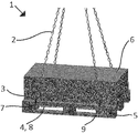
- FIG. 1 illustrates a lifting system according to an embodiment of the invention carrying a pallet with a load
- FIG. 2 illustrates the same lifting system without the pallet and the load
- FIG. 3 is a side view of the lifting system with pallet and load shown in FIG. 1 ,
- FIG. 4 is an end view of the lifting system with pallet and load shown in FIG. 1 ,
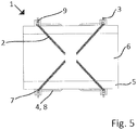
- FIG. 5 is a top view of the lifting system with pallet and load shown in FIG. 1 ,
- FIG. 6 illustrates a carrier element of a lifting system according to an embodiment of the invention
- FIG. 7 is a top view of the same carrier element
- FIG. 8 illustrates partly a carrier element according to another embodiment of the invention being mounted within a pallet with a load.
- FIGS. 1 and 2 illustrate a lifting system 1 according to an embodiment of the invention, with and without a pallet 5 with a load 6 , respectively.
- the suspension device 2 is constituted by a 4-part chain sling 2 with hooks 3 at the open ends of the chains.
- the two carrier elements 4 each consists of a distance bracket 8 and a supporting beam 7 , at each end of which is mounted a transverse lifting bolt 9 , with which the hooks 3 of the suspension device are in engagement.
- the lifting system 1 is used by mounting the carrier elements 4 transversely through the pallet 5 under the “load layer” thereof, after which the hooks 3 of the suspension device ( 2 ) are fastened to the ends of the supporting beams 7 of the carrier elements 4 , and the pallet 5 with the load 6 can be lifted by means of a crane (not shown) having hold of the suspension device 2 .
- the distance brackets 8 which are arranged so that they are horizontal when the supporting elements 4 are mounted within the pallet 5 , are dimensioned so that the carrier elements 4 can just pass between the supporting blocks of the pallet 5 . This means that the carrier elements 4 cannot be displaced in the longitudinal direction of the pallet 5 and, therefore, do not need any adjustment to be optimally positioned, as long as they are correctly orientated.
- FIGS. 3-5 illustrate the lifting system 1 with more details as seen from different angles, whereas FIGS. 6 and 7 show more details of the carrier element 4 .
- FIG. 8 illustrates partly a carrier element 4 according to another embodiment of the invention being mounted within a pallet 5 with a load 6 .
- the underside of the supporting beam 7 is bevelled 10 at both ends of the supporting beam 7 for facilitating the mounting of the carrier element 4 within the pallet 5 .
Abstract
Description
-
- 1. Lifting system
- 2. Chain sling
- 3. Hook
- 4. Carrier element
- 5. Pallet
- 6. Load
- 7. Supporting beam
- 8. Distance bracket
- 9. Lifting bolt
- 10. Bevelled underside of supporting beam
Claims (11)
Applications Claiming Priority (4)
| Application Number | Priority Date | Filing Date | Title |
|---|---|---|---|
| EP16175732 | 2016-06-22 | ||
| EP16175732.3A EP3260408B1 (en) | 2016-06-22 | 2016-06-22 | A lifting system and a carrier element for such a lifting system |
| EP16175732.3 | 2016-06-22 | ||
| PCT/EP2017/062402 WO2017220276A1 (en) | 2016-06-22 | 2017-05-23 | A lifting system and a carrier element for such a lifting system |
Publications (2)
| Publication Number | Publication Date |
|---|---|
| US20190330029A1 US20190330029A1 (en) | 2019-10-31 |
| US11214467B2 true US11214467B2 (en) | 2022-01-04 |
Family
ID=56411388
Family Applications (1)
| Application Number | Title | Priority Date | Filing Date |
|---|---|---|---|
| US16/310,359 Active US11214467B2 (en) | 2016-06-22 | 2017-05-23 | Lifting system and a carrier element for such a lifting system |
Country Status (11)
| Country | Link |
|---|---|
| US (1) | US11214467B2 (en) |
| EP (1) | EP3260408B1 (en) |
| JP (1) | JP7015250B2 (en) |
| CN (2) | CN109071183B (en) |
| AU (1) | AU2017283005B2 (en) |
| CA (1) | CA3018030A1 (en) |
| DK (1) | DK3260408T3 (en) |
| ES (1) | ES2701309T3 (en) |
| PL (1) | PL3260408T3 (en) |
| PT (1) | PT3260408T (en) |
| WO (1) | WO2017220276A1 (en) |
Cited By (1)
| Publication number | Priority date | Publication date | Assignee | Title |
|---|---|---|---|---|
| CN116639580A (en) * | 2023-05-31 | 2023-08-25 | 溧阳市裕达机械有限公司 | Quick hoisting accessory is used to ring mould granulator |
Families Citing this family (1)
| Publication number | Priority date | Publication date | Assignee | Title |
|---|---|---|---|---|
| CN116142945B (en) * | 2023-04-17 | 2023-06-16 | 安徽数智建造研究院有限公司 | Auxiliary device for subway station roof construction |
Citations (14)
| Publication number | Priority date | Publication date | Assignee | Title |
|---|---|---|---|---|
| US2459207A (en) * | 1945-04-16 | 1949-01-18 | William W Worthington | Material handling mechanism |
| US2700568A (en) * | 1949-08-06 | 1955-01-25 | Meili Louis | Accessory for lifting hoists |
| US2721756A (en) * | 1952-12-01 | 1955-10-25 | Markussen Markus | Cargo pallets |
| US2974994A (en) * | 1957-01-30 | 1961-03-14 | Metro Engineering Company Ltd | Lifting bridle construction |
| US3065987A (en) * | 1962-01-29 | 1962-11-27 | Aeroquip Corp | Pallet lifting attachment |
| US3239265A (en) | 1964-04-03 | 1966-03-08 | Scibilia Frank | Cargo pallet sling |
| US3493128A (en) * | 1967-09-08 | 1970-02-03 | Boussois Souchon Neuvesel Sa | Device for the storage,handling and transportation of fragile plates |
| FR2058748A5 (en) * | 1969-09-24 | 1971-05-28 | Cazenove Arnaud De | |
| US4550940A (en) | 1984-01-27 | 1985-11-05 | Schweikert Glen E | Pallet-bar lift and support apparatus |
| US4736975A (en) * | 1986-12-31 | 1988-04-12 | Nabisco Brands, Inc. | Method and apparatus for loading and unloading palletized loads |
| US5340180A (en) * | 1991-08-01 | 1994-08-23 | Paper Systems, Inc. | Apparatus for securing contained material |
| US6565136B1 (en) * | 2001-11-03 | 2003-05-20 | Michael J. Parker | Lifting device for palletized loads |
| JP2009269708A (en) | 2008-05-08 | 2009-11-19 | Yuzo Sakamoto | Pallet hanger |
| US7810861B1 (en) | 2007-09-28 | 2010-10-12 | The United States Of America As Represented By The Secretary Of The Navy | Hoisting device, transporting system, and methods |
Family Cites Families (6)
| Publication number | Priority date | Publication date | Assignee | Title |
|---|---|---|---|---|
| EP0220560B1 (en) * | 1985-10-11 | 1992-12-23 | Hans Wilcke | Loading device, particularly for vehicles, with two tipping arms, particularly hydraulically operated |
| JPH0592137U (en) * | 1992-05-11 | 1993-12-14 | ミサワホーム株式会社 | Phosphorous wood unit for unloading |
| JP2003312979A (en) | 2002-04-22 | 2003-11-06 | Sekisui House Ltd | Hoisting lug for panel material |
| CN201301164Y (en) * | 2008-06-20 | 2009-09-02 | 上海外高桥造船有限公司 | Bracket |
| CN101723237B (en) * | 2010-01-22 | 2013-03-13 | 中交四航局第二工程有限公司 | Novel soft rope strut type hanger for box girder |
| JP2015086032A (en) | 2013-10-30 | 2015-05-07 | 瀬戸内産業株式会社 | Palette hoisting auxiliary tool |
-
2016
- 2016-06-22 DK DK16175732.3T patent/DK3260408T3/en active
- 2016-06-22 PL PL16175732T patent/PL3260408T3/en unknown
- 2016-06-22 ES ES16175732T patent/ES2701309T3/en active Active
- 2016-06-22 PT PT16175732T patent/PT3260408T/en unknown
- 2016-06-22 EP EP16175732.3A patent/EP3260408B1/en active Active
-
2017
- 2017-05-23 WO PCT/EP2017/062402 patent/WO2017220276A1/en active Application Filing
- 2017-05-23 CN CN201780024859.8A patent/CN109071183B/en active Active
- 2017-05-23 JP JP2018561272A patent/JP7015250B2/en active Active
- 2017-05-23 US US16/310,359 patent/US11214467B2/en active Active
- 2017-05-23 AU AU2017283005A patent/AU2017283005B2/en active Active
- 2017-05-23 CN CN202211282633.7A patent/CN115583565A/en active Pending
- 2017-05-23 CA CA3018030A patent/CA3018030A1/en active Pending
Patent Citations (14)
| Publication number | Priority date | Publication date | Assignee | Title |
|---|---|---|---|---|
| US2459207A (en) * | 1945-04-16 | 1949-01-18 | William W Worthington | Material handling mechanism |
| US2700568A (en) * | 1949-08-06 | 1955-01-25 | Meili Louis | Accessory for lifting hoists |
| US2721756A (en) * | 1952-12-01 | 1955-10-25 | Markussen Markus | Cargo pallets |
| US2974994A (en) * | 1957-01-30 | 1961-03-14 | Metro Engineering Company Ltd | Lifting bridle construction |
| US3065987A (en) * | 1962-01-29 | 1962-11-27 | Aeroquip Corp | Pallet lifting attachment |
| US3239265A (en) | 1964-04-03 | 1966-03-08 | Scibilia Frank | Cargo pallet sling |
| US3493128A (en) * | 1967-09-08 | 1970-02-03 | Boussois Souchon Neuvesel Sa | Device for the storage,handling and transportation of fragile plates |
| FR2058748A5 (en) * | 1969-09-24 | 1971-05-28 | Cazenove Arnaud De | |
| US4550940A (en) | 1984-01-27 | 1985-11-05 | Schweikert Glen E | Pallet-bar lift and support apparatus |
| US4736975A (en) * | 1986-12-31 | 1988-04-12 | Nabisco Brands, Inc. | Method and apparatus for loading and unloading palletized loads |
| US5340180A (en) * | 1991-08-01 | 1994-08-23 | Paper Systems, Inc. | Apparatus for securing contained material |
| US6565136B1 (en) * | 2001-11-03 | 2003-05-20 | Michael J. Parker | Lifting device for palletized loads |
| US7810861B1 (en) | 2007-09-28 | 2010-10-12 | The United States Of America As Represented By The Secretary Of The Navy | Hoisting device, transporting system, and methods |
| JP2009269708A (en) | 2008-05-08 | 2009-11-19 | Yuzo Sakamoto | Pallet hanger |
Non-Patent Citations (1)
| Title |
|---|
| International Search Report and Written Opinion received in PCT application No. PCT/EP2017/062402, dated Nov. 9, 2017, 11 pages. |
Cited By (2)
| Publication number | Priority date | Publication date | Assignee | Title |
|---|---|---|---|---|
| CN116639580A (en) * | 2023-05-31 | 2023-08-25 | 溧阳市裕达机械有限公司 | Quick hoisting accessory is used to ring mould granulator |
| CN116639580B (en) * | 2023-05-31 | 2024-04-12 | 溧阳市裕达机械有限公司 | Quick hoisting accessory is used to ring mould granulator |
Also Published As
| Publication number | Publication date |
|---|---|
| AU2017283005A1 (en) | 2018-10-11 |
| DK3260408T3 (en) | 2018-12-17 |
| AU2017283005B2 (en) | 2022-10-20 |
| CN109071183A (en) | 2018-12-21 |
| JP7015250B2 (en) | 2022-02-02 |
| PL3260408T3 (en) | 2019-03-29 |
| PT3260408T (en) | 2018-12-18 |
| CN109071183B (en) | 2023-03-03 |
| EP3260408B1 (en) | 2018-10-17 |
| CA3018030A1 (en) | 2017-12-28 |
| CN115583565A (en) | 2023-01-10 |
| JP2019520283A (en) | 2019-07-18 |
| WO2017220276A1 (en) | 2017-12-28 |
| US20190330029A1 (en) | 2019-10-31 |
| ES2701309T3 (en) | 2019-02-21 |
| EP3260408A1 (en) | 2017-12-27 |
Similar Documents
| Publication | Publication Date | Title |
|---|---|---|
| US11214467B2 (en) | Lifting system and a carrier element for such a lifting system | |
| EP2043939B1 (en) | Detection frame for a lifting device | |
| EP2907770A1 (en) | System for the packing and transport of sheets of glass | |
| US9132994B2 (en) | Method for loading oversized merchandise onto a container ship | |
| KR20130136136A (en) | Crane assembly for lifting steel and lifting method using the same | |
| KR20060035704A (en) | The length adjustable wire sling | |
| TW201433524A (en) | Support element for supporting containers to be transported on a cargo ship, container for transporting freight on a cargo ship, method for supporting a container and a lashing bridge for supporting a container | |
| WO2019081810A1 (en) | Method and coupling means for locking together intermodal containers being transported on a ship | |
| EP0053009A2 (en) | A load lifting attachment for use with a fork lift truck, hoist, crane or the like | |
| US4671418A (en) | Apparatus for lashing goods | |
| US20200002137A1 (en) | Apparatus and method for carrying elongate construction elements | |
| KR20100088224A (en) | Jig for loading ship assembly having slant bottom and loading method using the same | |
| US6565136B1 (en) | Lifting device for palletized loads | |
| DK2853512T3 (en) | A device for connecting a lifting means, such as a crane, to an object to be lifted | |
| KR20180038125A (en) | Coil lifter | |
| US1840972A (en) | Apparatus for stacking heavy sheets | |
| JP2014101151A (en) | Panel hoisting device | |
| BE1017839A3 (en) | Transport device for wall element, includes support arm for locating on length side of element and wall hook for fixing around top side of element | |
| RU2397942C1 (en) | Crane gripper | |
| US20230322526A1 (en) | Lifting apparatus for hoisting a gyratory crusher spider | |
| US5087167A (en) | Lifting shoe assembly for use on sheet lifters | |
| JP2018184227A (en) | Support equipment of cargo handling pallet | |
| WO2016185338A1 (en) | Vehicle body carrier and method of loading a vehicle onto such a carrier | |
| EP1456109B1 (en) | Device for moving a load by means of a hoisting crane or the like | |
| US20090057352A1 (en) | Load securing hod tray |
Legal Events
| Date | Code | Title | Description |
|---|---|---|---|
| FEPP | Fee payment procedure |
Free format text: ENTITY STATUS SET TO UNDISCOUNTED (ORIGINAL EVENT CODE: BIG.); ENTITY STATUS OF PATENT OWNER: LARGE ENTITY |
|
| AS | Assignment |
Owner name: CRH CONCRETE A/S, DENMARK Free format text: ASSIGNMENT OF ASSIGNORS INTEREST;ASSIGNOR:NIELSEN, ESBEN;REEL/FRAME:047843/0074 Effective date: 20181008 |
|
| STPP | Information on status: patent application and granting procedure in general |
Free format text: DOCKETED NEW CASE - READY FOR EXAMINATION |
|
| STPP | Information on status: patent application and granting procedure in general |
Free format text: RESPONSE TO NON-FINAL OFFICE ACTION ENTERED AND FORWARDED TO EXAMINER |
|
| STPP | Information on status: patent application and granting procedure in general |
Free format text: RESPONSE AFTER FINAL ACTION FORWARDED TO EXAMINER |
|
| STPP | Information on status: patent application and granting procedure in general |
Free format text: DOCKETED NEW CASE - READY FOR EXAMINATION |
|
| STPP | Information on status: patent application and granting procedure in general |
Free format text: NON FINAL ACTION MAILED |
|
| STPP | Information on status: patent application and granting procedure in general |
Free format text: RESPONSE TO NON-FINAL OFFICE ACTION ENTERED AND FORWARDED TO EXAMINER |
|
| STPP | Information on status: patent application and granting procedure in general |
Free format text: FINAL REJECTION MAILED |
|
| STPP | Information on status: patent application and granting procedure in general |
Free format text: RESPONSE AFTER FINAL ACTION FORWARDED TO EXAMINER |
|
| STPP | Information on status: patent application and granting procedure in general |
Free format text: NOTICE OF ALLOWANCE MAILED -- APPLICATION RECEIVED IN OFFICE OF PUBLICATIONS |
|
| STPP | Information on status: patent application and granting procedure in general |
Free format text: PUBLICATIONS -- ISSUE FEE PAYMENT VERIFIED |
|
| STCF | Information on status: patent grant |
Free format text: PATENTED CASE |