US11214080B2 - Recording device - Google Patents
Recording device Download PDFInfo
- Publication number
- US11214080B2 US11214080B2 US16/810,303 US202016810303A US11214080B2 US 11214080 B2 US11214080 B2 US 11214080B2 US 202016810303 A US202016810303 A US 202016810303A US 11214080 B2 US11214080 B2 US 11214080B2
- Authority
- US
- United States
- Prior art keywords
- tray
- state
- support member
- medium
- main body
- Prior art date
- Legal status (The legal status is an assumption and is not a legal conclusion. Google has not performed a legal analysis and makes no representation as to the accuracy of the status listed.)
- Active, expires
Links
Images


Classifications
-
- B—PERFORMING OPERATIONS; TRANSPORTING
- B41—PRINTING; LINING MACHINES; TYPEWRITERS; STAMPS
- B41J—TYPEWRITERS; SELECTIVE PRINTING MECHANISMS, i.e. MECHANISMS PRINTING OTHERWISE THAN FROM A FORME; CORRECTION OF TYPOGRAPHICAL ERRORS
- B41J11/00—Devices or arrangements of selective printing mechanisms, e.g. ink-jet printers or thermal printers, for supporting or handling copy material in sheet or web form
- B41J11/58—Supply holders for sheets or fan-folded webs, e.g. shelves, tables, scrolls, pile holders
-
- B—PERFORMING OPERATIONS; TRANSPORTING
- B41—PRINTING; LINING MACHINES; TYPEWRITERS; STAMPS
- B41J—TYPEWRITERS; SELECTIVE PRINTING MECHANISMS, i.e. MECHANISMS PRINTING OTHERWISE THAN FROM A FORME; CORRECTION OF TYPOGRAPHICAL ERRORS
- B41J13/00—Devices or arrangements of selective printing mechanisms, e.g. ink-jet printers or thermal printers, specially adapted for supporting or handling copy material in short lengths, e.g. sheets
- B41J13/10—Sheet holders, retainers, movable guides, or stationary guides
- B41J13/106—Sheet holders, retainers, movable guides, or stationary guides for the sheet output section
-
- B—PERFORMING OPERATIONS; TRANSPORTING
- B41—PRINTING; LINING MACHINES; TYPEWRITERS; STAMPS
- B41J—TYPEWRITERS; SELECTIVE PRINTING MECHANISMS, i.e. MECHANISMS PRINTING OTHERWISE THAN FROM A FORME; CORRECTION OF TYPOGRAPHICAL ERRORS
- B41J11/00—Devices or arrangements of selective printing mechanisms, e.g. ink-jet printers or thermal printers, for supporting or handling copy material in sheet or web form
- B41J11/007—Conveyor belts or like feeding devices
-
- B—PERFORMING OPERATIONS; TRANSPORTING
- B41—PRINTING; LINING MACHINES; TYPEWRITERS; STAMPS
- B41J—TYPEWRITERS; SELECTIVE PRINTING MECHANISMS, i.e. MECHANISMS PRINTING OTHERWISE THAN FROM A FORME; CORRECTION OF TYPOGRAPHICAL ERRORS
- B41J13/00—Devices or arrangements of selective printing mechanisms, e.g. ink-jet printers or thermal printers, specially adapted for supporting or handling copy material in short lengths, e.g. sheets
- B41J13/10—Sheet holders, retainers, movable guides, or stationary guides
- B41J13/103—Sheet holders, retainers, movable guides, or stationary guides for the sheet feeding section
Definitions
- the present disclosure relates to a recording device that performs recording on a medium.
- a recording device represented by a facsimile, a printer, or the like
- a device provided with a sheet discharge tray that receives a recording sheet recorded and discharged, and a configuration in which the sheet discharge tray is provided with a plurality of trays, and a sheet discharge receiving surface is extended by pulling out each of the trays.
- JP-A-2009-046271 describes an example of such a configuration.
- the sheet discharge tray when the sheet discharge tray is provided with a first tray and a second tray configured to protrude from the device main body further than the first tray, and the second tray completely protrudes from the device main body, the second tray needs to be supported by the first tray.
- a rail supporting the first tray in the device main body extends to a front surface of the device as far as possible from the viewpoint of stably supporting the first tray.
- the rail supporting the first tray is extended to the front surface of the device, it may be necessary to form a escape shape in the first tray or the second tray so that the first tray or the second tray does not interfere with the rail when each tray is accommodated in the device main body.
- the structure of the first tray or the second tray may be complicated, resulting in an increase in cost.
- a recording device including a medium receiving tray configured to switch between a first state in which the medium receiving tray is accommodated in the device main body and a second state in which the medium receiving tray most protrudes from the device main body, and that receives the medium discharged toward an outside of the device main body in the second state or a state of protruding from the device main body toward the second state from the first state, in which the medium receiving tray is configured to include a first tray configured to be displaced with respect to a rail provided in the device main body, and a second tray configured to be displaced with respect to the first tray, the second tray further protruding from the device main body than the first tray in the second state and being supported by the first tray, the device main body includes at least one support member configured to be at an advanced position at which the support member advances with respect to a side surface of the medium receiving tray and a retracted position at which the support member retracts from the advanced position, the support member is at a position protruding from an end
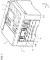
- FIG. 1 is a perspective view of a printer in a state where a discharge tray is accommodated.
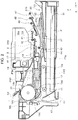
- FIG. 2 is a side sectional view illustrating a sheet transport path of the printer.
- FIG. 3 is a perspective view of the printer in a state where the discharge tray is pulled out halfway.
- FIG. 4 is a perspective view of the printer in a state where the discharge tray is most pulled out.
- FIG. 5 is a perspective view of a rail and a support member.
- FIG. 6 is a perspective view of the discharge tray.
- FIG. 7 is a partial sectional view of the discharge tray.
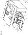
- FIG. 8 is a perspective view of the accommodated discharge tray, the support member, and a driving object.
- FIG. 9 is a perspective view of the discharge tray, the support member, and the driving object in a state of pulled out halfway.
- FIG. 10 is a perspective view of the discharge tray, the support member, and the driving object in a state of most pulled out.
- FIG. 11 is a sectional perspective view of the discharge tray and the rail.
- FIG. 13 is a plan view illustrating a discharge tray locking mechanism.
- FIG. 14 is a side sectional view illustrating the sheet transport path of the printer.
- FIG. 15 is a partially enlarged perspective view of a front surface of the printer.
- FIG. 16 is a sectional view cut at a position of a side wall of a first sheet cassette.
- FIG. 17 is a sectional view cut at the position of the side wall of the first sheet cassette.
- a recording device includes a device main body that includes a recording unit which records on a medium, and a medium receiving tray configured to switch between a first state in which the medium receiving tray is accommodated in the device main body and a second state in which the medium receiving tray most protrudes from the device main body, and that receives the medium discharged toward an outside of the device main body in the second state or a state of protruding from the device main body toward the second state from the first state, in which the medium receiving tray is configured to include a first tray configured to be displaced with respect to a rail provided in the device main body, and a second tray configured to be displaced with respect to the first tray, the second tray further protruding from the device main body than the first tray in the second state and being supported by the first tray, the device main body includes at least one support member configured to be at an advanced position at which the support member advances with respect to a side surface of the medium receiving tray and a retracted position at which the support member retracts from the advanced position, the support member is
- At least one support member configured to be at the advanced position that advances with respect to the medium receiving tray and the retracted position that retracts from the advanced position.
- the support member is at the retracted position when the medium receiving tray is in the first state, and the support member is at the advanced position and supports the first tray from below when the medium receiving tray is in the second state. Therefore, the medium receiving tray in the second state can be stably supported.
- the second tray is positioned below the first tray, the support member is pressed toward a side surface of the second tray by a pressing member, the support member is at the retracted position and presses against the side surface of the second tray, when the medium receiving tray is in the first state, the second tray is pulled out from a region facing the support member, and the support member is switched from the retracted position to the advanced position, when the medium receiving tray is switched from the first state to the second state, and the support member is switched from the advanced position to the retracted position by the second tray pushing the support member against a pressing force of the pressing member, when the medium receiving tray is switched from the second state to the first state.
- the support member is engaged with the second tray and switches between the advanced position and the retracted position in accordance with the displacement operation of the second tray. Therefore, the configuration which displaces the support member can be configured at low cost.
- the support member presses against the side surface of the second tray when the medium receiving tray is in the first state, it is possible to suppress rattling of the medium receiving tray in the first state.
- a surface of the support member pressed by the second tray when the medium receiving tray is switched from the second state to the first state is formed by a surface intersecting a displacement direction of the second tray.
- a surface pressed by the second tray when the medium receiving tray is switched from the second state to the first state is formed by a surface intersecting a displacement direction of the second tray. Therefore, the possibility that the second tray is caught by the support member can be suppressed.
- the support member is provided on each side of the second tray.
- the first tray can be supported more stably.
- the recording device further includes a drive unit configured to displace the medium receiving tray and provided at a position facing one side surface of the medium receiving tray in the device main body, in which the drive unit includes two pinion gears, the first tray includes a first rack portion that meshes with one pinion gear of the two pinion gears, the second tray includes a second rack portion that meshes with an other pinion gear of the two pinion gears, and the first tray and the second tray are displaced by a rotation of the two pinion gears.
- the drive unit includes two pinion gears
- the first tray includes a first rack portion that meshes with one pinion gear of the two pinion gears
- the second tray includes a second rack portion that meshes with an other pinion gear of the two pinion gears
- the first tray and the second tray are displaced by a rotation of the two pinion gears.
- the support member includes a first support member on a side on which the drive unit is provided of both sides of the second tray, and a second support member on a side opposite from a side on which the first support member is provided, and the second support member presses the second tray with a pressing force stronger than a pressing force of the first support member, when the medium receiving tray is in the first state.
- the support member includes the first support member on the side where the drive unit is provided of both sides of the second tray, and the second support member on a side opposite to the side on which the first support member is provided, that is, the support member is provided on both sides of the second tray. Therefore, the first tray can be supported more reliably and appropriately.
- the second support member on the side opposite to the side on which the drive unit is provided presses the second tray with a stronger pressing force than that of the first support member on the side on which the drive unit is provided, that is, the second tray is pressed toward the drive unit. Therefore, the meshing between the pinion gear and the second rack portion provided on the second tray can be appropriately maintained.
- the medium receiving tray is configured to be pulled out from the device main body
- the recording device further includes a restriction unit configured to switch between a permission state in which the medium receiving tray is permitted to be pulled out from the device main body and a restriction state in which the pulling out from the device main body is restricted.
- the medium receiving tray is configured to be pulled out from the device main body, the inside of the device main body can be easily accessed by pulling out the medium receiving tray from the device main body.
- the restriction unit that can switch between a state of permitting the medium receiving tray to be pulled out from the device main body and a state of regulating to be pulled out from the device main body. Therefore, it is possible to prevent the medium receiving tray from being pulled out carelessly.
- the restriction unit includes a restriction portion provided on the device main body, a restricted portion provided on the first tray and configured to switch between a state in which the restricted portion is configured to be engaged with the restriction portion and a state in which the restriction portion is not configured to be engaged with the restriction portion, and an operation portion, provided on the first tray, for switching the state of the restricted portion.
- the restriction unit can be obtained with a simple configuration.
- the recording device further includes a first medium transport path which is a medium transport path facing the recording unit, and configured to transport the medium in a first direction which is a medium transport direction when recording on the medium is performed and in a second direction opposite from the first direction, a reverse path on which a surface of the medium is reversed, a second medium transport path that guides the medium recorded by the recording unit to the reverse path, a third medium transport path that is positioned below the second medium transport path, guides the medium on which recording is performed by the recording unit to the reverse path, and is different from the second medium transport path, a path forming portion that forms a portion of a lower side of the third medium transport path, and is positioned above the medium receiving tray mounted on the device main body, and a medium storage cassette positioned below the medium receiving tray and configured to accommodate the medium and be detached from the device main body, in which the path forming portion is configured to be displaced downward in a state where the medium receiving tray and the medium storage cassette are removed from the device main body
- the path forming portion can be displaced downward in a state where the medium receiving tray and the medium storage cassette are removed from the device main body, and a portion of the third medium transport path is exposed when the supporting member is displaced downward. Therefore, when a jam occurs in the third medium transport path, jam processing can be easily performed.
- the path forming portion is provided with an abutting portion on which the medium receiving tray abuts in a state where the path forming portion is displaced downward, and the medium receiving tray abuts on the abutting portion in a state where the path forming portion is displaced downward, so that the restriction unit is prevented from being switched to the restriction state.
- the abutting portion provided on the medium receiving tray prevents the restriction unit from switching to the restriction state when the path forming portion is displaced downward. Therefore, it is possible to prevent the medium receiving tray from being mounted in an inappropriate state, that is, in a state where the path forming portion is displaced downward, and to prevent damage or the like caused by forcibly mounting the medium receiving tray in the inappropriate state.
- a direction along an X axis is a device width direction and a direction intersecting a sheet transport direction, that is, a sheet width direction.
- the ⁇ X direction is a right direction when viewed from a user in a case in which a front surface of the device faces the user, and the +X direction is a left direction, similarly.
- a direction along a Y axis is a device depth direction
- the +Y direction is a direction from a rear surface to the front surface of the device, and a first direction.
- the ⁇ Y direction is a direction from the front surface to the rear surface of the device and is a second direction.
- a direction along a Z axis is a vertical direction
- the +Z direction is vertically upward
- the ⁇ Z direction is vertically downward.
- a side surface provided with an operation portion 5 among the side surfaces constituting a periphery of the device is the front surface of the device.
- an ink jet printer 1 which is an example of a recording device is a so-called multifunctional peripheral provided with a scanner portion 3 on an upper portion of a device main body 2 .
- the ink jet printer 1 is abbreviated as a printer 1 .
- the device main body 2 has a function of recording on a recording sheet as an example of a medium, and the scanner portion 3 has a function of reading a document.
- the scanner portion 3 is provided with an automatic document feeder (ADF) that automatically feeds a set document.
- ADF automatic document feeder
- the device main body 2 is provided with a transport path (described later) for transporting the recording sheet and a recording head 9 (refer to FIG. 2 ) as an example of a recording unit.
- a transport path (described later) for transporting the recording sheet and a recording head 9 (refer to FIG. 2 ) as an example of a recording unit.
- two medium storage cassettes specifically, a first sheet cassette 31 and a second sheet cassette 32 are detachably provided.
- the device main body 2 is configured to be able to set and feed the sheet from the rear surface of the device in addition to setting the sheet to the first sheet cassette 31 and the second sheet cassette 32 .
- Reference numeral 7 denotes a cover for opening and closing a sheet setting port (not illustrated) when setting the sheet from the rear surface of the device.
- the device main body 2 is provided with the operation portion 5 that performs various operations of the printer 1 on the front surface of the device.
- the operation portion 5 is provided with a display portion and a plurality of operation buttons and is provided to be tiltable.
- a discharge tray 50 serving as a medium receiving tray that receives the recording sheet recorded and discharged is provided on a lower side of the operation portion 5 . As illustrated in FIG. 1 , the discharge tray 50 is provided so as to be able to be in a state of being accommodated inside the device main body 2 and a state of being pulled out from the device main body 2 (refer to FIGS. 3 and 4 ).
- the discharge tray 50 can be pulled out from the device main body 2 .
- the discharge tray 50 will be described in detail later.
- FIG. 2 the illustration of the second sheet cassette 32 is omitted.
- the recording sheet is transported to a transport drive roller 16 through a reverse roller 21 constituting a reverse path RR regardless of a feeding path, and is transported to a recording region by the recording head 9 by the transport drive roller 16 .
- the printer 1 is provided with a sheet feeding path K 1 for feeding the recording sheet from the first sheet cassette 31 , a sheet feeding path K 2 for feeding the recording sheet from the second sheet cassette 32 below the first sheet cassette 31 , and a sheet feeding path K 3 for manually feeding the recording sheet from the upper rear of the device.
- the printer 1 is provided with a first sheet transport path FR 1 that is a sheet transport path facing the recording head 9 and that can transport the recording sheet in the first direction (+Y direction), which is the sheet transport direction when recording on the recording sheet, and the second direction ( ⁇ Y direction) opposite thereto, the reverse path RR for reversing the surface of the recording sheet, a second sheet transport path FR 2 for guiding the recording sheet on which recording is performed to the reverse path RR, and a third sheet transport path FR 3 positioned vertically below the second sheet transport path FR 2 , guides the recorded recording sheet to the reverse path RR, and different from the second sheet transport path FR 2 .
- a first sheet transport path FR 1 that is a sheet transport path facing the recording head 9 and that can transport the recording sheet in the first direction (+Y direction), which is the sheet transport direction when recording on the recording sheet, and the second direction ( ⁇ Y direction) opposite thereto
- the reverse path RR for reversing the surface of the recording sheet
- a second sheet transport path FR 2
- the first sheet transport path FR 1 is a sheet transport path between the transport drive roller 16 and a first discharge drive roller 41 .
- the second sheet transport path FR 2 is a sheet transport path between the transport drive roller 16 and a driven roller 14 a through a driven roller 14 d .
- the third sheet transport path FR 3 is a sheet transport path between a second discharge drive roller 47 and the driven roller 14 a through a reverse drive roller 43 .
- the reverse path RR is a sheet transport path between the driven roller 14 a and a driven roller 14 c .
- reference numeral FR 4 is a sheet transport path (fourth sheet transport path) between the driven roller 14 c and the transport drive roller 16 .
- the recording sheet is fed by a feeding roller 11 in the sheet feeding path K 1 .
- the feeding roller 11 is supported by a support member 12 that swings around a swing shaft 12 a , and the feeding roller 11 advances and retreats with respect to a recording sheet P accommodated in the first sheet cassette 31 by the swing of the support member 12 .
- the second sheet cassette 32 (not illustrated in FIG. 2 ) provided under the first sheet cassette 31 is also provided with a similar feeding mechanism (not illustrated).
- the reverse roller 21 is formed to have a largest diameter as compared with other rollers, and reverses the recording sheet in a curved manner. Driven rollers 14 a , 14 b , 14 c , and 14 d are provided around the reverse roller 21 .
- the recording sheet fed through the sheet feeding paths K 1 and K 2 is sent to the transport drive roller 16 through the reverse path RR and the fourth sheet transport path FR 4 .
- the recording sheet fed through the sheet feeding path K 3 is sent to the transport drive roller 16 through the fourth sheet transport path FR 4 .
- the recording sheet sent along the ⁇ Y direction through the second sheet transport path FR 2 is sent to the transport drive roller 16 through the reverse path RR and the fourth sheet transport path FR 4 .
- the recording sheet sent along the ⁇ Y direction through the third sheet transport path FR 3 is sent to the transport drive roller 16 through the reverse path RR and the fourth sheet transport path FR 4 .
- the recording sheet sent to the transport drive roller 16 driven by a drive source (not illustrated) is nipped by the transport drive roller 16 and a transport driven roller 17 driven to rotate, is sent to a region facing the recording head 9 , that is, a recording region, and recording is performed.
- a carriage 8 provided with the recording head 9 is reciprocated in the X axis direction by a power source (not illustrated) while being guided by a carriage guide shaft 19 extending in the X axis direction.
- the recording head 9 ejects an ink onto the recording sheet as the carriage 8 moves.
- a support member 18 is provided at a position facing the recording head 9 , and the recording sheet on which recording is performed by the recording head 9 is supported by the support member 18 .
- the first discharge drive roller 41 rotationally driven, and a first discharge driven roller 42 driven to rotate which send the recording sheet on which recording is performed downstream are provided.
- the first discharge drive roller 41 and the first discharge driven roller 42 driven to rotate are a pair of rollers that are first positioned downstream of the recording head 9 .
- the second discharge drive roller 47 rotationally driven and a second discharge driven roller 48 driven to rotate are provided.
- the feeding roller 11 and the reverse roller 21 are driven by a first motor (not illustrated), the transport drive roller 16 and the first discharge drive roller 41 are driven by a second motors (not illustrated), and the second discharge drive roller 47 and the reverse drive roller 43 are driven by a third motor (not illustrated).
- the discharge tray 50 is driven using a fourth motor (not illustrated) as a drive source.
- the recording sheet on which the recording is performed is sent to the reverse path RR.
- the sheet transport path at that time either the second sheet transport path FR 2 or the third sheet transport path FR 3 can be selected.
- a path length of the third sheet transport path FR 3 is longer than a path length of the second sheet transport path FR 2 . Therefore, the control unit (not illustrated) of the printer 1 has a sheet length threshold, and when the length of the recording sheet exceeds the threshold, the third sheet transport path FR 3 is selected, and when the length of the recording sheet is equal to or less than the threshold, the second sheet transport path FR 2 is selected.
- the transport drive roller 16 , the first discharge drive roller 41 , and the second discharge drive roller 47 are reversed. As a result, the recording sheet is transported along the ⁇ Y direction on the second sheet transport path FR 2 and reaches the reverse path RR.
- the recording sheet is transported along the +Y direction until a trailing edge of the sheet reaches a driven roller 49 provided near the upstream of the second discharge drive roller 47 . Thereafter, the second discharge drive roller 47 is reversed.
- a flap 39 that can swing around a swing shaft 39 a is provided upstream of the driven roller 49 , and when the recording sheet is sent to the third sheet transport path FR 3 , raises an end portion of the flap 39 in the +Y direction upward. As a result, the recording sheet is sent to the third sheet transport path FR 3 and sent to the reverse path RR.
- the +Y direction region of the third sheet transport path FR 3 can be exposed, and the third sheet transport path FR 3 can be accessed from the front of the device, and the printer 1 is configured to be removable a jammed recording sheet when a jam occurs in the third sheet transport path FR 3 .
- a path forming portion 27 that forms a portion of the lower side of the third sheet transport path FR 3 is provided above the first sheet cassette 31 .
- the path forming portion 27 is provided so as to be swingable by pushing down an end portion 27 b in the +Y direction with a swing shaft 27 a as the swing center.
- the end portion 27 b cannot be pushed down when the discharge tray 50 and the first sheet cassette 31 are mounted as illustrated in FIG. 15 , the end portion 27 b can be pushed down by removing the discharge tray 50 and the first sheet cassette 31 from the device main body 2 , and the path forming portion 27 can be displaced downward as illustrated in FIG. 14 .
- the jammed recording sheet can be removed.
- the rotation regulation mechanism can be configured to include a mechanism including a one-way clutch or a mechanism including a planetary gear mechanism, for example.
- the second discharge drive roller 47 rotates normally when the third motor rotates normally, and reverses when the third motor rotates reversely.
- the discharge tray 50 as a medium receiving tray can be switched between a first state (refer to FIG. 1 ) accommodated in the device main body 2 and a second state (refer to FIG. 4 ) that protrudes most from the device main body 2 .
- a first state (refer to FIG. 1 ) accommodated in the device main body 2
- a second state (refer to FIG. 4 ) that protrudes most from the device main body 2 .
- the recording sheet discharged toward the outside of the device main body 2 is received.
- the discharge tray 50 is provided with a first tray 52 displaceable with respect to a rail 60 a (refer to FIG. 5 ) provided in the device main body 2 , and a second tray 51 displaceable with respect to the first tray 52 , protrudes from the device main body 2 than the first tray 52 in the second state, and is supported by the first tray 52 .
- FIG. 5 illustrates a configuration of the left side surface of the storage region of the discharge tray 50 , the same configuration is also provided on the right side surface in a bilaterally symmetric structure.
- the second tray 51 is provided on a lower side of the first tray 52 .
- the second tray 51 has a front wall 51 b at the end portion in the +Y direction, that is, a protruding direction of each tray from the device main body 2 , and the front wall 51 b functions as a stopper that suppresses jumping-out of the recording sheet to be discharged.
- the front wall 51 b is provided with a recessed portion 51 c for hooking fingers.
- the discharge tray 50 In a state where the discharge tray 50 is in the first state, that is, the storage state, and the operation portion 5 is completely closed, as illustrated in FIG. 1 , the front surfaces of the front wall 51 b , the first sheet cassette 31 , the second sheet cassette 32 , the operation portion 5 , the device main body 2 , and the scanner portion 3 are flush with each other.
- a support portion 52 b is formed on the lower surface of the first tray 52 so as to extend in the Y axis direction
- a supported portion 51 e is formed on the upper surface of the second tray 51 so as to extend in the Y axis direction.
- the second tray 51 is supported by the first tray 52 by placing the supported portion 51 e on the support portion 52 b from above.
- FIG. 7 illustrates a structure of the end portions of the first tray 52 and the second tray 51 in the ⁇ X direction, the same configuration is also provided on the end portion in the +X direction in a bilaterally symmetric structure.
- a first rack portion 52 a is formed on the side surface of the first tray 52 in the ⁇ X direction along the Y axis direction, and a second rack portion 51 a is formed on the side surface of the second tray 51 in the ⁇ X direction along the Y axis direction. These rack portions will be described later.
- FIG. 7 illustrates the supported portion 52 c formed on the side surface of the first tray 52 in the ⁇ X direction.
- the rail 60 a provided in the device main body 2 enters the lower side of the supported portion 52 c , so that the first tray 52 is supported by the rail 60 a .
- the supported portion 52 c illustrated in FIG. 7 is supported by the rail 60 a (refer to FIG. 11 ) provided on the right side of the device main body 2 .
- the rail 60 a illustrated in FIG. 5 supports a supported portion 52 c provided on the side surface of the first tray 52 in the +X direction.
- a guide slope 60 d is provided on a frame 60 that forms the storage region of the discharge tray 50 in the device main body 2 .
- the guide slope 60 d guides the end portion of the discharge tray 50 in the ⁇ Y direction to a correct mounting position.
- the above-described supported portion 52 c is guided on the rail 60 a by the guide slope 60 d.
- the first tray 52 is provided with an operation portion 55 and a hook 56 .
- the discharge tray 50 is in a state of being held so as not to drop off from the device main body 2 .
- the discharge tray 50 is restricted so as not to be pulled out from the device main body 2 .
- a restriction unit 58 is provided, and the restriction unit 58 is provided with the hook 56 as a restricted portion, the restriction portion 57 , and the operation portion 55 (refer to FIG. 6 ).
- the hook 56 can swing in the +a direction and the ⁇ a direction in FIG. 13 around the swing shaft (not illustrated), and is pressed by an elastic portion (not illustrated) toward a direction indicated by the solid line in FIG. 13 , that is, the state where the hook 56 can engage with the restriction portion 57 ( ⁇ a direction). In this state, since the hook 56 is in a restriction state where the hook 56 can be engaged with the restriction portion 57 , the pulling out of the discharge tray 50 in the +Y direction is restricted.
- the hook 56 moves, the state where the pulling out of the discharge tray 50 is restricted is eliminated, and the discharge tray 50 can be detached from the device main body 2 .
- the path forming portion 27 can be displaced downward as described with reference to FIG. 14 , and the third sheet transport path FR 3 can be exposed.
- the path forming portion 27 is provided with an abutting portion 27 c , and in a state where the path forming portion 27 is displaced downward, as illustrated in FIG. 17 , a tip end of the first tray 52 constituting the discharge tray 50 abuts on the abutting portion 27 c , and the mounting of the first tray 52 is hindered. As a result, the restriction unit 58 is prevented from switching to the restriction state. With such a configuration, it is possible to prevent the discharge tray 50 from being mounted in an inappropriate state, that is, in a state where the path forming portion 27 is displaced downward, and to prevent damage or the like caused by forcibly mounting the discharge tray 50 in the inappropriate state.
- a support surface 60 b is provided below the rail 60 a .
- the support surface 60 b supports the second tray 51 when the second tray 51 is accommodated in the device main body 2 . That is, the second tray 51 is supported by the support surface 60 b until protruding from the device main body 2 , and after protruding from the device main body 2 , the second tray 51 is supported by the support portion 52 b (refer to FIG. 7 ) of the first tray 52 as described above.
- the rail 60 a and the support surface 60 b have a predetermined angle with respect to the horizontal plane, and are formed to be inclined upward in the +Y direction.
- the discharge tray 50 protruding from the device main body 2 is inclined upward in the +Y direction.
- the support member is provided in the protruding direction of the first tray 52 , that is, in the +Y direction with respect to the end portion of the rail 60 a in the +Y direction.
- the support member is provided at a position facing the left side surface of the second tray 51 and a position facing the right side surface of the second tray 51 in the device main body 2 .
- the support member provided at a position facing the left side surface of the second tray 51 is indicated by reference numeral 63 B.
- the support member provided at a position facing the right side surface of the second tray 51 is indicated by reference numeral 63 A. That is, in the present embodiment, the support member includes a first support member 63 A and a second support member 63 B.
- a support member 63 when it is not necessary to distinguish the first support member 63 A and the second support member 63 B, these are simply referred to as a support member 63 .
- the support member 63 is provided so as to be able to protrude from an opening portion 60 c formed in the frame 60 toward the second tray 51 , that is, provided so as to be able to advance and retreat with respect to the second tray 51 .
- FIGS. 5, 8, 9 , and 11 illustrate a state where the support member 63 is in a retracted position
- FIG. 10 illustrates a state where the support member 63 is in an advanced position.
- FIG. 11 illustrates a state where the support member 63 is in the retracted position for convenience.
- the support member 63 is pressed toward the side surface of the second tray 51 by a coil spring 67 which is an example of a pressing member.
- a coil spring 67 which is an example of a pressing member.
- the illustration of the coil spring 67 is omitted.
- the support member 63 When the discharge tray 50 is in the first state, that is, when the second tray 51 is accommodated in the device main body 2 , the support member 63 is in the retracted position, and is pressed against the side surface 51 d of the second tray 51 by the spring force of the coil spring 67 . This aspect is illustrated in FIG. 8 .
- the discharge tray 50 switches from the first state to the second state from this state, as illustrated in the change from FIG. 9 to FIG. 10 , the second tray 51 comes out of the region facing the support member 63 , and the support member 63 is switched from the retracted position to the advanced position by a pressing force of the coil spring 67 .
- a hook 63 d is formed on the support member 63 .
- the configuration for displacing the support member 63 can be configured at low cost.
- the support member 63 is positioned in the +Y direction than the end portion of the rail 60 a in the +Y direction.
- a virtual line and reference numeral M 1 indicate an escape shape, more specifically a groove, required for the side surface 51 d of the second tray 51 when the rail 60 a is further extended in the +Y direction from the length illustrated in FIG. 11 .
- a range Ya illustrated in FIG. 11 illustrates an example of a length extending the rail 60 a .
- a escape shape as indicated by reference numeral M 1 in FIG. 8 is required, and there is a possibility of increasing the cost accompanying the complexity of a structure. Although not preferable in appearance, such a problem can be avoided by providing the support member 63 as described above.
- the support member 63 is formed with a slope 63 c as illustrated in FIG. 12 .
- the slope 63 c is a surface pushed to the end portion of the second tray 51 in the ⁇ Y direction when the discharge tray 50 is switched from the second state to the first state.
- the slope 63 c is formed by a surface that intersects the Y direction. Such a slope 63 c can suppress the possibility that the second tray 51 is caught by the support member 63 .
- the support members 63 are provided on both sides of the second tray 51 , the first tray 52 can be supported more reliably and appropriately.
- the support member 63 may be provided only on one side surface of the second tray 51 .
- the discharge tray 50 is configured to be displaced between the first state and the second state by receiving the power of a motor (not illustrated), thereby improving user convenience.
- a mechanism for displacing the discharge tray 50 is provided at a position facing one side surface of the discharge tray 50 , specifically, in the ⁇ X direction with respect to the discharge tray 50 .
- a driving object 64 illustrated in FIGS. 9 to 11 is driven by a motor (not illustrated) and constitutes a portion of a drive unit driving the discharge tray 50 .
- the first tray 52 and the second tray 51 perform the displacement operations.
- FIG. 8 illustrating the first state of the discharge tray 50
- the second pinion portion 65 is meshed with the second rack portion 51 a of the second tray 51
- the first pinion portion 66 does not mesh with the first rack portion 52 a of the first tray 52 . Therefore, when the driving object 64 starts to rotate from the state of FIG. 8 , only the second tray 51 starts the displacement operation in the +Y direction at first, and the first tray 52 remains stopped.
- the second pinion portion 65 releases the meshing with the second rack portion 51 a of the second tray 51 as illustrated in FIG. 10 .
- the discharge tray 50 moves from the second state toward the first state, the first tray 52 and the second tray 51 supported by the first tray 52 are displaced in the ⁇ Y direction by the meshing of the first rack portion 52 a of the first tray 52 and the first pinion portion 66 .
- the second pinion portion 65 meshes with the second rack portion 51 a of the second tray 51
- the first pinion portion 66 releases the meshing with the first rack portion 52 a of the first tray 52 .
- the second tray 51 is displaced in the ⁇ Y direction and returns to the first state of the discharge tray 50 illustrated in FIG. 8 .
- the second state of the discharge tray 50 includes a first position illustrated in FIG. 3 and a second position that protrudes further than the first position as illustrated in FIG. 4 .
- the first position is a position when, for example, A4 size sheet is discharged so that the longitudinal direction is along the Y axis direction
- the second position is a position when, for example, A3 size sheet is discharged so that the longitudinal direction is along the Y axis direction.
- a control portion (not illustrated) that controls a fourth motor (not illustrated) that is a power source of the discharge tray 50 positions the discharge tray 50 based on the sheet size information obtained from the driver information.
- the support member 63 includes the first support member 63 A on the side where the driving object 64 is provided and the second support member 63 B on the side opposite to the side on which the first support member 63 A is provided of both sides of the second tray 51 .
- the coil spring 67 (refer to FIG. 12 ) that presses each support member may be different from the coil spring that presses the first support member 63 A and the coil spring that presses the second support member 63 B.
- a coil spring that exerts a stronger spring force than the coil spring that presses the first support member 63 A is adopted as the coil spring that presses the second support member 63 B.
- the second tray 51 When the discharge tray 50 is in the first state, the second tray 51 is configured to be pressed toward the driving object 64 (refer to FIG. 8 ). As a result, the meshing between the second rack portion 51 a provided on the second tray 51 and the second pinion portion 65 can be appropriately maintained.
- the support member 63 may be configured to be advanced and retracted by an actuator such as a motor or a solenoid. In that case, it is preferable to provide a sensor for detecting the positions of the first tray 52 and the second tray 51 .
Abstract
Description
Claims (10)
Applications Claiming Priority (6)
| Application Number | Priority Date | Filing Date | Title |
|---|---|---|---|
| JPJP2019-042324 | 2019-03-08 | ||
| JP2019042324 | 2019-03-08 | ||
| JP2019-042324 | 2019-03-08 | ||
| JP2019-194111 | 2019-10-25 | ||
| JPJP2019-194111 | 2019-10-25 | ||
| JP2019194111A JP7367456B2 (en) | 2019-03-08 | 2019-10-25 | recording device |
Publications (2)
| Publication Number | Publication Date |
|---|---|
| US20200282750A1 US20200282750A1 (en) | 2020-09-10 |
| US11214080B2 true US11214080B2 (en) | 2022-01-04 |
Family
ID=72335720
Family Applications (1)
| Application Number | Title | Priority Date | Filing Date |
|---|---|---|---|
| US16/810,303 Active 2040-08-05 US11214080B2 (en) | 2019-03-08 | 2020-03-05 | Recording device |
Country Status (1)
| Country | Link |
|---|---|
| US (1) | US11214080B2 (en) |
Citations (10)
| Publication number | Priority date | Publication date | Assignee | Title |
|---|---|---|---|---|
| US4748457A (en) * | 1987-01-05 | 1988-05-31 | American Home Products Corporation (Del.) | Recording device for recording information on a paper medium |
| JP2003095512A (en) | 2001-09-26 | 2003-04-03 | Seiko Epson Corp | Paper discharging stacker and recording apparatus having the same |
| US6595514B2 (en) * | 2000-10-20 | 2003-07-22 | Ricoh Company, Ltd. | Sheet feeding device and image forming apparatus including the sheet feeding device |
| US20060001209A1 (en) * | 2004-07-02 | 2006-01-05 | Funai Electric Co., Ltd. | Printer |
| US20060017794A1 (en) * | 2004-07-20 | 2006-01-26 | Seiko Epson Corporation | Medium feeding device and recording apparatus or liquid ejecting apparatus incorporating the same |
| JP2007290801A (en) | 2006-04-21 | 2007-11-08 | Funai Electric Co Ltd | Inkjet printer and image forming device |
| JP2009046271A (en) | 2007-08-21 | 2009-03-05 | Ricoh Co Ltd | Image forming device |
| US8272637B2 (en) * | 2008-01-31 | 2012-09-25 | Brother Kogyo Kabushiki Kaisha | Sheet tray unit with three tray portions and tray stopper, and image recording device comprising said sheet tray unit |
| US8672429B2 (en) * | 2010-09-24 | 2014-03-18 | Fuji Xerox Co., Ltd. | Image forming apparatus including a recessed handle portion for an extension portion |
| US20140103603A1 (en) * | 2012-10-12 | 2014-04-17 | Ricoh Company, Ltd. | Paper output tray, paper output unit incorporating same, and image forming apparatus incorporating same |
-
2020
- 2020-03-05 US US16/810,303 patent/US11214080B2/en active Active
Patent Citations (10)
| Publication number | Priority date | Publication date | Assignee | Title |
|---|---|---|---|---|
| US4748457A (en) * | 1987-01-05 | 1988-05-31 | American Home Products Corporation (Del.) | Recording device for recording information on a paper medium |
| US6595514B2 (en) * | 2000-10-20 | 2003-07-22 | Ricoh Company, Ltd. | Sheet feeding device and image forming apparatus including the sheet feeding device |
| JP2003095512A (en) | 2001-09-26 | 2003-04-03 | Seiko Epson Corp | Paper discharging stacker and recording apparatus having the same |
| US20060001209A1 (en) * | 2004-07-02 | 2006-01-05 | Funai Electric Co., Ltd. | Printer |
| US20060017794A1 (en) * | 2004-07-20 | 2006-01-26 | Seiko Epson Corporation | Medium feeding device and recording apparatus or liquid ejecting apparatus incorporating the same |
| JP2007290801A (en) | 2006-04-21 | 2007-11-08 | Funai Electric Co Ltd | Inkjet printer and image forming device |
| JP2009046271A (en) | 2007-08-21 | 2009-03-05 | Ricoh Co Ltd | Image forming device |
| US8272637B2 (en) * | 2008-01-31 | 2012-09-25 | Brother Kogyo Kabushiki Kaisha | Sheet tray unit with three tray portions and tray stopper, and image recording device comprising said sheet tray unit |
| US8672429B2 (en) * | 2010-09-24 | 2014-03-18 | Fuji Xerox Co., Ltd. | Image forming apparatus including a recessed handle portion for an extension portion |
| US20140103603A1 (en) * | 2012-10-12 | 2014-04-17 | Ricoh Company, Ltd. | Paper output tray, paper output unit incorporating same, and image forming apparatus incorporating same |
Also Published As
| Publication number | Publication date |
|---|---|
| US20200282750A1 (en) | 2020-09-10 |
Similar Documents
| Publication | Publication Date | Title |
|---|---|---|
| US10221024B2 (en) | Sheet transport apparatus and image recording apparatus | |
| US8493639B2 (en) | Image recording device | |
| JP3391159B2 (en) | Media transport device | |
| JP5014106B2 (en) | Image reading and recording device | |
| US11319176B2 (en) | Recording apparatus | |
| US9156637B2 (en) | Tray unit and image recording device | |
| US9346292B2 (en) | Recording apparatus | |
| JP6852763B2 (en) | Image recording device | |
| US11214080B2 (en) | Recording device | |
| JP4419733B2 (en) | Image forming apparatus | |
| JP2013209179A (en) | Recording apparatus | |
| JP7367456B2 (en) | recording device | |
| US10979587B2 (en) | Recording apparatus | |
| JP4126567B2 (en) | Control method for discharge stacker lifting apparatus, discharge stacker lift apparatus, recording apparatus, and liquid ejecting apparatus | |
| JP2022101994A (en) | Recorder | |
| JP2009262357A (en) | Recording apparatus | |
| JP7456173B2 (en) | Media feeding device, recording device | |
| JP4006597B2 (en) | Automatic paper feeder and recording apparatus provided with the automatic paper feeder | |
| JP3965582B2 (en) | Automatic paper feeder and recording apparatus provided with the automatic paper feeder | |
| JP6892624B2 (en) | Feeding device and recording device | |
| JP6292371B2 (en) | Recording device | |
| JP3965581B2 (en) | Automatic paper feeder and recording apparatus provided with the automatic paper feeder | |
| JP5888191B2 (en) | Image recording device | |
| JP5321362B2 (en) | Sheet conveying apparatus and image recording apparatus | |
| JP4947313B2 (en) | Image recording device |
Legal Events
| Date | Code | Title | Description |
|---|---|---|---|
| AS | Assignment |
Owner name: SEIKO EPSON CORPORATION, JAPAN Free format text: ASSIGNMENT OF ASSIGNORS INTEREST;ASSIGNORS:TAMAI, SATOSHI;OIZUMI, TAKAO;KOMATSU, YUKI;REEL/FRAME:052029/0739 Effective date: 20200120 |
|
| FEPP | Fee payment procedure |
Free format text: ENTITY STATUS SET TO UNDISCOUNTED (ORIGINAL EVENT CODE: BIG.); ENTITY STATUS OF PATENT OWNER: LARGE ENTITY |
|
| STPP | Information on status: patent application and granting procedure in general |
Free format text: DOCKETED NEW CASE - READY FOR EXAMINATION |
|
| STPP | Information on status: patent application and granting procedure in general |
Free format text: NOTICE OF ALLOWANCE MAILED -- APPLICATION RECEIVED IN OFFICE OF PUBLICATIONS |
|
| STPP | Information on status: patent application and granting procedure in general |
Free format text: PUBLICATIONS -- ISSUE FEE PAYMENT RECEIVED |
|
| STPP | Information on status: patent application and granting procedure in general |
Free format text: PUBLICATIONS -- ISSUE FEE PAYMENT VERIFIED |
|
| STCF | Information on status: patent grant |
Free format text: PATENTED CASE |