JP4947313B2 - Image recording device - Google Patents
Image recording device Download PDFInfo
- Publication number
- JP4947313B2 JP4947313B2 JP2008093557A JP2008093557A JP4947313B2 JP 4947313 B2 JP4947313 B2 JP 4947313B2 JP 2008093557 A JP2008093557 A JP 2008093557A JP 2008093557 A JP2008093557 A JP 2008093557A JP 4947313 B2 JP4947313 B2 JP 4947313B2
- Authority
- JP
- Japan
- Prior art keywords
- paper feed
- feed tray
- feeding
- arm body
- recording medium
- Prior art date
- Legal status (The legal status is an assumption and is not a legal conclusion. Google has not performed a legal analysis and makes no representation as to the accuracy of the status listed.)
- Expired - Fee Related
Links
- 238000000926 separation method Methods 0.000 claims description 35
- 238000003860 storage Methods 0.000 claims description 34
- 238000011144 upstream manufacturing Methods 0.000 claims description 23
- 238000001514 detection method Methods 0.000 claims description 21
- 210000000078 claw Anatomy 0.000 claims description 13
- 238000003780 insertion Methods 0.000 claims description 6
- 230000037431 insertion Effects 0.000 claims description 6
- 230000008021 deposition Effects 0.000 claims description 2
- 238000013459 approach Methods 0.000 description 10
- 230000000694 effects Effects 0.000 description 7
- 229920003002 synthetic resin Polymers 0.000 description 7
- 239000000057 synthetic resin Substances 0.000 description 7
- 239000007799 cork Substances 0.000 description 6
- 230000005540 biological transmission Effects 0.000 description 5
- 230000006870 function Effects 0.000 description 5
- 230000007246 mechanism Effects 0.000 description 5
- 230000002093 peripheral effect Effects 0.000 description 5
- 239000011521 glass Substances 0.000 description 4
- 230000009471 action Effects 0.000 description 3
- 230000000875 corresponding effect Effects 0.000 description 3
- 238000009825 accumulation Methods 0.000 description 2
- 230000008859 change Effects 0.000 description 2
- 230000002452 interceptive effect Effects 0.000 description 2
- 239000000463 material Substances 0.000 description 2
- 239000002184 metal Substances 0.000 description 2
- 238000000034 method Methods 0.000 description 2
- 230000002079 cooperative effect Effects 0.000 description 1
- 230000002950 deficient Effects 0.000 description 1
- 238000000605 extraction Methods 0.000 description 1
- 238000002347 injection Methods 0.000 description 1
- 239000007924 injection Substances 0.000 description 1
- 239000004973 liquid crystal related substance Substances 0.000 description 1
- 238000004519 manufacturing process Methods 0.000 description 1
- 238000012986 modification Methods 0.000 description 1
- 230000004048 modification Effects 0.000 description 1
- 238000003825 pressing Methods 0.000 description 1
- 238000012545 processing Methods 0.000 description 1
- 229920005989 resin Polymers 0.000 description 1
- 239000011347 resin Substances 0.000 description 1
- 230000003245 working effect Effects 0.000 description 1
Images


Description
本発明は、画像記録部に対して、紙または合成樹脂製シートのカットシート等の用紙(以下、被記録媒体という)を1枚ずつ給送する給紙装置を備えた画像記録装置の構成に関するものである。 The present invention relates to a configuration of an image recording apparatus including a paper feeding device that feeds paper (hereinafter, referred to as a recording medium) such as paper or a cut sheet of a synthetic resin sheet to an image recording unit one by one. Is.
従来、インクジェット式の画像記録装置等の記録部と対向するように被記録媒体を給送するため、基端部を装置筐体に上下回動自在に軸支したアーム体の先端部に給送ローラを備えた構成が知られている。この構成によれば、上面が開放された給送トレイに堆積収容された用紙の最上面に、アーム体を押えるばねの付勢力により給送ローラが押圧されている。そして、この状態で給送ローラが回転駆動されることにより、用紙の端部が給紙トレイの給送方向下流側の端部に形成された傾斜状の分離壁に突き当てられて、最上層のみの用紙が分離されて画像記録部の方向に給送されるのである(特許文献1参照)。その場合、給紙ローラの周面をゴム等の摩擦係数の大きい部材にて構成する一方、給紙トレイにおける上記給紙ローラが当接する底面個所にはコルク板などの同じく摩擦係数の大きい板を貼り付けする。これにより、給紙トレイ内の用紙の枚数が少なくなったときに、用紙の重送が発生しないようにしている。 Conventionally, in order to feed a recording medium so as to face a recording part of an ink jet type image recording apparatus or the like, the base end part is fed to the distal end part of an arm body that is pivotally supported by the apparatus housing in a vertically rotatable manner. A configuration with a roller is known. According to this configuration, the feeding roller is pressed against the uppermost surface of the paper stacked and accommodated in the feeding tray whose upper surface is opened by the urging force of the spring that presses the arm body. In this state, the feeding roller is driven to rotate, so that the end of the sheet abuts against the inclined separation wall formed at the end of the sheet feeding tray on the downstream side in the feeding direction. Only the sheet is separated and fed in the direction of the image recording unit (see Patent Document 1). In this case, the peripheral surface of the paper feed roller is made of a member having a large coefficient of friction such as rubber, and a plate having the same coefficient of friction such as a cork plate is provided at the bottom surface of the paper feed tray where the paper feed roller contacts. Paste. As a result, when the number of sheets in the sheet feeding tray is reduced, the sheets are not double-fed.
しかしながら、給紙トレイ内の用紙がなくなったとき、上記給紙ローラが給紙トレイの底面のコルク板に当接した状態で回転駆動すると、このコルク板や給紙ローラの周面が過度に摩耗したり、給紙ローラの回転がロックされたりする。その結果、駆動モータに不具合が生ずる虞があるという問題があった。これらの問題を解消するため、特許文献2及び3に開示されているように、アーム体の先端部下面側に、上下回動可能な作動体からなる離間手段を設けた機構が案出されている。これにより、アーム体の先端部の給紙ローラが給紙トレイの底部に接近すると、作動体が先に底部に当接して、給紙ローラを底部から離間させるように押し上げるのである。
However, when the paper in the paper feed tray runs out and the paper feed roller is driven to rotate with the cork plate in contact with the bottom surface of the paper feed tray, the cork plate and the peripheral surface of the paper feed roller are excessively worn. Or the rotation of the paper feed roller is locked. As a result, there is a problem that the drive motor may be defective. In order to solve these problems, as disclosed in
他方、特許文献4に記載の画像記録装置に示すように、装置筐体の下端部に底板が設けられており、その上の空間がトレイ収納部に形成されている。そして、このトレイ収納部に対して給送トレイを実質上水平方向に挿抜することができるようにしているのが通常である。そして、特許文献2及び3に開示されているように、アーム体には、その回動基部側に用紙の幅方向(給送方向と直交する方向)に延びるカムフォロア(図示せず)が設けられている。他方、給紙トレイの左右両側板には、当該給紙トレイを水平状にて挿抜するときに、上記カムフォロアに摺接する高さが変化するカム部(図示せず)が設けられている。このため、給紙トレイを挿抜するとき、当該給紙トレイの給送方向下流側端の傾斜分離板の上を給紙ローラが乗り越えるように、アーム体を強制的に昇降させる構成が開示されている。
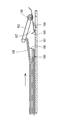
ところで、特許文献3及び4に記載され、図11に示す作動体104における給送方向上流側端には、斜め上向きに突出する傾斜部105が設けられており、画像記録装置の装置筐体内に挿入した状態の給紙トレイに用紙を追加供給するときに、前記傾斜部にて給紙ローラの下面側に用紙が円滑に導入され易くする構成であった。
Incidentally, an
しかしながら、給紙トレイ100が装置筐体から引き出された状態では、給紙ローラ102が装置筐体の底板101に当接するように、アーム体103が筐体の奥側に向かって下向きに大きく傾く。そのときには、離間手段における作動体104の作動体104は、その給送方向上流側端部が底板101に接近するような姿勢まで傾くから、作動体104における傾斜部105とアーム体103の下面側との間に大きな隙間107ができる。
However, when the
給紙トレイ100内に堆積収容された用紙106のうちの上層部のものの先端部が給紙トレイ100の給送方向下流側端の傾斜分離板108を乗り越えて配置されている状態で、ユーザが給紙トレイ100を装置筐体内に押し込むと、図11に示すように、傾斜部105とアーム体103の下面側との間の隙間107に、用紙106の先端部が嵌まった状態となる。このまま、給紙トレイ100をさらに装置筐体の奥側に押し込み、給紙トレイ100の傾斜分離板108の個所が作動体104に接近し、上記カムフォロアとカム部との協働作用にて作動体104が上昇しようとする。しかし、この作動体104とアーム体103との間に用紙106の先端部が挟まっているので、作動体104は上昇不能となる。ユーザがこのことを知らずに、さらに給紙トレイ100を装置筐体の奥側に押し込むと、作動体104が傾斜分離板108に衝突するなどして、作動体104やアーム体103が破損する虞があるという問題があった。
In the state where the leading end portion of the upper layer of the
本発明は、上記の従来の課題を解決すべくなされたものであり、アーム体が装置筐体の底板に当接または接近したとき作動体をアーム体の下面に接近するように係合させる手段を備えることにより、給紙トレイの押し込み時におけるアーム体や作動体の破損を防止できるようにした画像記録装置を提供することを目的とするものである。 The present invention has been made to solve the above-described conventional problems, and is a means for engaging the operating body so as to approach the lower surface of the arm body when the arm body contacts or approaches the bottom plate of the apparatus housing. It is an object of the present invention to provide an image recording apparatus that can prevent the arm body and the operating body from being damaged when the paper feed tray is pushed in.
前記目的を達成するため、請求項1に記載の発明の画像記録装置は、被記録媒体に対する記録部を備えた装置筺体に、シート状の被記録媒体を堆積状態で収容可能な収容部を有する給紙トレイを実質上水平方向に挿抜可能に収納するトレイ収納部が設けられてなる画像記録装置であって、前記トレイ収納部は、前記給紙トレイの少なくとも一部を支持するための支持部を備え、前記装置筐体内には、前記給紙トレイの前記収容部に収容されている被記録媒体の堆積量に応じて上下動可能なアーム体を配置し、前記アーム体の先端部には最上位の被記録媒体に当接しながら回転駆動する給送ローラを配置し、前記アーム体には、当該アーム体に基端部が上下回動可能に装着されて前記給送ローラよりも給送方向の上流側に延びる作動体と、前記作動体の前記給送方向の上流側の下面に設けられて前記被記録媒体の最上面に当接し、且つ前記被記録媒体が存在しないとき前記収容部の底面に形成された開放部に嵌まる検出部と、前記検出部よりも給送方向下流側の作動体に設けられ、前記収容部の底面に当接して給送ローラを前記収容部の底面から離間させる作動部と、を有する離間手段を備え、前記給紙トレイを前記装置筐体から引き出すとき、前記作動体と前記アーム体との間に被記録媒体が進入可能な間隙がなくなる状態に両者を係合させる係合手段を備え、且つ前記係合手段による係合を解除するための解除手段を備えているものである。 In order to achieve the above object, an image recording apparatus according to a first aspect of the present invention has an accommodating portion capable of accommodating a sheet-like recording medium in a stacked state in an apparatus housing having a recording unit for the recording medium. An image recording apparatus provided with a tray storage unit that stores a paper feed tray so that it can be inserted and removed in a substantially horizontal direction, wherein the tray storage unit supports at least a part of the paper feed tray. wherein the the device housing, a vertically movable arm member is arranged in accordance with the amount of deposition of the recording medium accommodated in the accommodating portion of the paper feed tray, the front end portion of the arm body A feeding roller that rotates while being in contact with the uppermost recording medium is disposed, and a base end portion of the arm body is attached to the arm body so that the base end can be turned up and down, and the feeding roller feeds more than the feeding roller. An operating body extending upstream in the direction; Detection that is provided on the lower surface of the moving body on the upstream side in the feeding direction, abuts on the uppermost surface of the recording medium, and fits into an open portion formed on the bottom surface of the housing portion when the recording medium does not exist And a working unit provided on the working body downstream in the feeding direction from the detecting unit, and a working unit contacting the bottom surface of the housing unit and separating the feeding roller from the bottom surface of the housing unit. provided, when pulling the paper feed tray from the device housing comprises an engagement means for the recording medium to engage both the state capable gap enters is eliminated between the actuating member and the arm member, and Release means for releasing engagement by the engagement means is provided.
請求項2に記載の発明は、請求項1に記載の画像記録装置において、前記解除手段は、前記収容部に被記録媒体が収容されている給紙トレイを装置筐体内に挿入したとき、前記収容されている被記録媒体又は前記収容部の底面に当接して前記係合手段の係合を解除するものである。 According to a second aspect of the present invention, in the image recording apparatus according to the first aspect, the release means inserts a paper feed tray in which the recording medium is stored in the storage portion into the apparatus housing. The engagement of the engaging means is released by contacting the recording medium accommodated or the bottom surface of the accommodating portion.
請求項3に記載の発明は、請求項1または2に記載の画像記録装置において、前記解除手段は、前記作動体における前記給送方向の下流側に延びる当接片であることを特徴とするものである。 According to a third aspect of the present invention, in the image recording apparatus according to the first or second aspect, the release means is a contact piece that extends downstream in the feeding direction of the operating body. Is.
請求項4に記載の発明は、請求項1乃至請求項3のいずれかに記載の画像記録装置において、前記作動体には、前記検出部よりも給送方向上流側に用紙誘い込み用の突出部を設け、前記突出部より前記作動体の回動中心側には、前記係合手段における一方の係合爪を備え、前記アーム体には前記係合爪に係脱する係止部を備えたものである。 According to a fourth aspect of the present invention, in the image recording apparatus according to any one of the first to third aspects of the present invention, the operating body has a protruding portion for guiding the paper upstream in the feeding direction from the detection portion. The engaging body is provided with one engaging claw in the engaging means on the rotation center side of the operating body from the protruding portion, and the arm body is provided with a locking portion that engages with and disengages from the engaging claw. Is.
請求項5に記載の発明は、請求項1乃至請求項4のいずれかに記載の画像記録装置において、前記給紙トレイには、当該給紙トレイを挿抜移動させるとき、前記アーム体及び前記作動体を前記給紙トレイの下流側端部から離間させる退避手段を備えたものである。 According to a fifth aspect of the present invention, in the image recording apparatus according to any one of the first to fourth aspects, when the paper feed tray is inserted into and removed from the paper feed tray, the arm body and the operation are provided. A retracting means for separating the body from the downstream end of the paper feed tray is provided.
請求項6に記載の発明は、請求項5に記載の画像記録装置において、前記退避手段の1つは、前記アーム体に設けられたカムフォロアと、前記給紙トレイの側部に形成されたカム部とからなり、前記退避手段の他の1つは、前記給紙トレイの給送方向の下流側部から立設する傾斜分離板であり、前記給紙トレイを挿抜移動させるとき、前記傾斜分離板の上端部が前記作動体の下面に摺接するように構成されているものである。 According to a sixth aspect of the present invention, in the image recording apparatus according to the fifth aspect, one of the retracting means includes a cam follower provided on the arm body and a cam formed on a side portion of the paper feed tray. The other one of the retracting means is an inclined separation plate standing from the downstream side in the feeding direction of the paper feed tray, and when the paper feed tray is inserted and removed, the tilt separation is performed. The upper end of the plate is configured to be in sliding contact with the lower surface of the operating body.
請求項7に記載の発明は、請求項1乃至6のいずれかに記載の画像記録装置において、前記装置筐体には、前記給紙トレイが前記装置筐体に収納されていないとき、前記解除手段の動作を無効にする無効化手段が設けられているものである。 According to a seventh aspect of the present invention, in the image recording apparatus according to any one of the first to sixth aspects, when the paper feed tray is not housed in the apparatus casing, the release is performed in the apparatus casing. An invalidating means for invalidating the operation of the means is provided.
上述のように、請求項1に記載の発明によれば、被記録媒体に対する記録部を備えた装置筺体に、シート状の被記録媒体を堆積状態で収容可能な収容部を有する給紙トレイを実質上水平方向に挿抜可能に収納するトレイ収納部が設けられてなる画像記録装置であって、前記トレイ収納部は、前記給紙トレイの少なくとも一部を支持するための支持部を備え、前記装置筐体内には、前記給紙トレイの前記収容部に収容されている被記録媒体の堆積量に応じて上下動可能なアーム体を配置し、前記アーム体の先端部には最上位の被記録媒体に当接しながら回転駆動する給送ローラを配置し、前記アーム体には、当該アーム体に基端部が上下回動可能に装着されて前記給送ローラよりも給送方向の上流側に延びる作動体と、前記作動体の前記給送方向の上流側の下面に設けられて前記被記録媒体の最上面に当接し、且つ前記被記録媒体が存在しないとき前記収容部の底面に形成された開放部に嵌まる検出部と、前記検出部よりも給送方向下流側の作動体に設けられ、前記収容部の底面に当接して給送ローラを前記収容部の底面から離間させる作動部と、を有する離間手段を備え、前記給紙トレイを前記装置筐体から引き出すとき、前記作動体と前記アーム体との間に被記録媒体が進入可能な間隙がなくなる状態に両者を係合させる係合手段を備え、且つ前記係合手段による係合を解除するための解除手段を備えているものである。 As described above, according to the first aspect of the present invention, the paper feed tray having the accommodating portion capable of accommodating the sheet-like recording medium in the accumulated state is provided in the apparatus housing having the recording portion for the recording medium. An image recording apparatus provided with a tray storage portion that is detachably stored in a substantially horizontal direction, wherein the tray storage portion includes a support portion for supporting at least a part of the paper feed tray, An arm body that can be moved up and down according to the amount of recording medium stored in the storage section of the paper feed tray is disposed in the apparatus housing, and the uppermost cover is disposed at the tip of the arm body. A feeding roller that rotates while being in contact with the recording medium is disposed, and a base end portion of the arm body is rotatably attached to the arm body so that the arm body is upstream of the feeding direction. And the feeding method of the working body A detection unit that is provided on a lower surface on the upstream side of the recording medium and that abuts on an uppermost surface of the recording medium and fits into an open portion formed on a bottom surface of the housing unit when the recording medium is not present; and the detection unit An operation unit that is provided on an operating body on the downstream side in the feeding direction, and has an operation unit that contacts the bottom surface of the housing unit and separates the feeding roller from the bottom surface of the housing unit, And an engagement means for engaging the recording medium in a state where there is no gap in which the recording medium can enter between the operating body and the arm body. Release means for releasing the connection is provided.
従って、前記収容部内に前記被記録媒体が収容されていないとき、前記収容部の底面に形成された開放部に離間手段が嵌まって、前記給送ローラが前記収容部の底面から離間する方向に前記アーム体を移動させるから、給送ローラが不用意に摩耗したり、駆動モータが焼きつくなどの故障も発生しない。しかも、前記給紙トレイを前記装置筐体から引き出すとき、前記離間手段と前記アーム体との間に被記録媒体が進入可能な間隙がなくなる状態に両者を係合させる係合手段を備えたから、給紙トレイの先端から被記録媒体がはみ出したでの、給紙トレイの押し込み時におけるアーム体や作動体の破損を確実に防止できるものである。さらに、前記係合手段による係合を解除するための解除手段を備えているものであるから、通常の給紙トレイに堆積収容した被記録媒体を給送ローラにて給送する動作も確保できるという効果を奏する。 Therefore, when the recording medium is not accommodated in the accommodating portion, the separating means is fitted in the open portion formed on the bottom surface of the accommodating portion, and the feeding roller is separated from the bottom surface of the accommodating portion. Therefore, the feeding roller does not wear carelessly, and the drive motor does not burn out. In addition, when the paper feed tray is pulled out from the apparatus housing, it is provided with engagement means for engaging the recording medium so that there is no gap into which the recording medium can enter between the separation means and the arm body. It is possible to reliably prevent damage to the arm body and the operating body when the recording medium is pushed out when the recording medium protrudes from the front end of the paper feeding tray. Further, since the release means for releasing the engagement by the engagement means is provided, the operation of feeding the recording medium accumulated and accommodated in the normal paper feed tray by the feed roller can be ensured. There is an effect.
請求項2に記載の発明によれば、前記解除手段は、前記収容部に被記録媒体が収容されている給紙トレイを装置筐体内に挿入したとき、前記収容されている被記録媒体又は前記収容部の底面に当接して前記係合手段の係合を解除するものであり、請求項1に記載の発明の効果に加えて、解除手段の構成が極めて簡単であり、製造コストの低減に寄与できるとともに、画像記録装置全体の高さを大きくする必要がなくコンパクトにできるという効果を奏する。 According to the second aspect of the present invention, when the paper feed tray in which the recording medium is stored in the storage portion is inserted into the apparatus housing, the release unit stores the recording medium stored in the storage unit or the recording medium. In addition to the effect of the invention of claim 1, the structure of the releasing means is extremely simple and reduces the manufacturing cost. It is possible to contribute, and there is an effect that it is not necessary to increase the height of the entire image recording apparatus and it can be made compact.
請求項3に記載の発明によれば、前記解除手段は、前記作動体における前記給送方向の下流側に延びる当接片であるから、請求項1に記載の発明の効果に加えて、離間手段と解除手段とが一体的に形成されていることになり、構成が一層コンパクト化できるという効果を奏する。
According to the invention described in
請求項4に記載の発明によれば、前記作動体には、前記検出部よりも給送方向上流側に用紙誘い込み用の突出部を設け、前記突出部より前記作動体の回動中心側には、前記係合手段における一方の係合爪を備え、前記アーム体には前記係合爪に係脱する係止部を備えたものである。従って、係合手段の構成が至極簡単となる。 According to the fourth aspect of the present invention, the operating body is provided with a paper guiding protrusion on the upstream side in the feeding direction with respect to the detection portion, and the operating body is located on the rotation center side of the operating body. Is provided with one engaging claw in the engaging means, and the arm body is provided with a locking portion that engages with and disengages from the engaging claw. Therefore, the configuration of the engaging means is extremely simple.
請求項5に記載の発明によれば、前記給紙トレイには、当該給紙トレイを挿抜移動させるとき、前記アーム体及び前記作動体を前記給紙トレイの下流側端部から離間させる退避手段を備えたものである。従って、給紙トレイを挿抜するときに、前記アーム体及び前記作動体が給紙トレイの先端部と干渉することなく乗り越えさせることができて、部品の損傷が無くなるという効果を奏する。
According to the invention described in
請求項6に記載の発明によれば、前記退避手段の1つは、前記アーム体に設けられたカムフォロアと、前記給紙トレイの側部に形成されたカム部とからなり、前記退避手段の他の1つは、前記給紙トレイの給送方向の下流側部から立設する傾斜分離板であり、前記給紙トレイを挿抜移動させるとき、前記傾斜分離板の上端部が前記作動体の下面に摺接するように構成されているものである。従って、給紙トレイの構成を利用して、退避手段を設けることができ、小型で、且つ最小構成部品でありながら、必要な機能を充足させることができる。
According to the invention described in
請求項7に記載の発明によれば、前記装置筐体には、前記給紙トレイが前記装置筐体に収納されていないとき、前記解除手段の動作を無効にする無効化手段が設けられているものである。 According to a seventh aspect of the present invention, the device casing is provided with invalidating means for invalidating the operation of the release means when the paper feed tray is not stored in the device casing. It is what.
従って、誤って、作動体56の給送方向上流側部位とアーム体20cと間に大きい隙間が形成されることを阻止して、作動体56の破損防止を確実にできる。
Accordingly, it is possible to prevent the working
次に、本発明を具体化した実施形態について図面を参照しながら詳細に説明する。図1は本発明の一実施形態である多機能型の画像記録装置1の全体斜視図、図2は記録部の左右中央部の側断面図、図3は排紙トレイ部を除いた状態の給紙トレイの平面図、図4は給紙トレイの斜視図、図5は駆動軸を除いた状態の給送手段の斜視図、図6は駆動軸を除いた状態の給送手段の平面図、図7はアーム体に離間手段がロックされた状態の側面図、図8は離間手段の係合手段を示す断面図、図9(A)〜(D)は給送トレイを引き抜きに伴う給送手段の昇降動作を示す説明図、図10(A)〜(C)は離間手段の動作を示す説明図、図11は従来の技術を示す説明図である。 Next, embodiments of the present invention will be described in detail with reference to the drawings. FIG. 1 is an overall perspective view of a multifunctional image recording apparatus 1 according to an embodiment of the present invention, FIG. 2 is a side sectional view of a left and right central portion of a recording unit, and FIG. FIG. 4 is a perspective view of the paper feed tray, FIG. 5 is a perspective view of the feeding means without the drive shaft, and FIG. 6 is a plan view of the feed means with the drive shaft removed. 7 is a side view showing a state in which the separating means is locked to the arm body, FIG. 8 is a cross-sectional view showing the engaging means of the separating means, and FIGS. 9A to 9D are views for feeding the feed tray when it is pulled out. FIGS. 10A to 10C are explanatory views showing the operation of the separating means, and FIG. 11 is an explanatory view showing the prior art.
[多機能装置1の基本構造]
図1に示すように、多機能装置1におけるハウジング2(請求項でいう装置筐体に相当)の前側(図1において手前側)には開口部2aが開口されており、その開口部2aには被記録媒体としての用紙を堆積状態で収容する上面開放状の給紙トレイ3がX軸線方向に沿って挿抜可能に装着されている。その給紙トレイ3の上面に排紙トレイ33が装着されている。なお、この「挿抜」とは、給紙トレイ3がハウジング2に対して着脱可能なもののみならず、ハウジング2から給紙トレイ3の大部分を引出した状態でも、ハウジング2に対して給紙トレイ3が外れない(着脱不能)ものも含む趣旨である。
[Basic structure of multi-function device 1]
As shown in FIG. 1, an
合成樹脂製のハウジング2の上部には、コピー機能やファクシミリ機能における原稿読取などのための画像読取装置5が配置されている。画像読取装置5は図示しない枢軸部を介してハウジング2の一側端に対して上下開閉回動可能に構成されている。また、画像読取装置5の上面は原稿載置用のガラス板で構成されており、このガラス板は、画像読取装置5の後端に対して枢軸を中心に上下回動可能な原稿カバー体6で覆われている。原稿カバー体6を上側に開けてガラス板の上に原稿を載置し、ガラス板の下方において主走査方向に往復移動する原稿読取り用のスキャナ(例えばCIS:Contact Image Sensor)によって原稿の画像が読取られる。
An
ハウジング2の上面であって原稿カバー体6の前方には、各種操作ボタンを備えた操作パネル部7と、操作手順や実行中の処理の状態を表示するための液晶表示装置8とが設けられている。各種操作ボタンとしては、スタートボタンや、ストップボタンなどを含み、これらの操作ボタンを押下することにより、各種の操作が行われる。また、多機能装置1の設定状態や各種の操作メッセージなどが必要に応じて表示される。
On the upper surface of the
また、ハウジング2の前面であって、開口部2aの上方には、外部メモリを挿入するための外部メモリ挿入部11が備えられている。外部メモリとは、例えば、コンパクトフラッシュ(登録商標)、スマートメディア(登録商標)、メモリスティック(登録商標)、SDカード(登録商標)、xD(登録商標)等が該当する。この外部メモリ挿入部11へ挿入された外部メモリに記憶されたデータは、多機能装置1の内部メモリ読み込まれ、記録装置によって用紙に記録される。
An external memory insertion portion 11 for inserting an external memory is provided on the front surface of the
次に、図2〜図5等を参照して記録部10及び給紙装置12について説明する。図2は記録部10及び給紙装置12の側断面図である。
Next, the
[記録部]
記録部10は、図2に示すように、上面が開放された箱型のメインフレーム(図示せず)とその左右一対の側板にて支持され、Y軸方向(主走査方向)に延びる横長の板状の第1及び第2ガイド部材15、16との間に形成される。記録部10における記録ヘッド(図示せず)が下面側に搭載されたキャリッジ13は、用紙搬送方向の上流側の第1ガイド部材15及び下流側の第2ガイド部材16に跨がって摺動自在に支持(搭載)されて往復移動可能となっている。
[Recording section]
As shown in FIG. 2, the
キャリッジ13を往復移動させるために、用紙搬送方向(矢印A方向)の下流側に配置された第2ガイド部材16の上面には、主走査方向(Y軸方向)に延びるように配置されたタイミングベルト(図示せず)がプーリ(図示せず)に巻回されており、そのタイミングベルトを駆動するCR(キャリッジ)モータ(図示せず)は第2ガイド部材16の下面に固定されている。
In order to reciprocate the
キャリッジ13における記録ヘッド14の下面と対峙するようにY軸方向に延びる扁平状のプラテン17は、前記両ガイド部材15、16の間であって、メインフレームの底板の上方に固定されている。プラテン17とハウジング2の底板2b(請求項にいう支持部に相当)との間が後述する給紙トレイ3を収納し、且つ挿抜できるトレイ収納部となる。ハウジング2の底板2bに対して給紙トレイ3の底部3aの少なくとも一部が支持される。
A
また、プラテン17を挟んで搬送上流側には、用紙を記録ヘッド14の下面に送るためのレジストローラ(搬送ローラ)対18が配置されており、プラテン17の下流側には記録済みの用紙を、給紙トレイ3の上面に設けられた排紙トレイ部33上に搬送するための排紙ローラ対19が配置されている。プラテン17は、レジストローラ(搬送ローラ)対18によって搬送されてきた用紙を、記録ヘッドとの間隙を一定にするように支持するのである。
In addition, a registration roller (conveyance roller)
[給紙装置]
給紙トレイ3に収容される被記録媒体は、以下便宜上用紙と述べることとするが、被記録媒体は普通紙のみならず、はがきや封筒等の厚紙や光沢紙等の特殊紙、さらには樹脂フィルム等も含む概念である。
[Paper Feeder]
The recording medium accommodated in the
次に、給紙装置12の構成について詳述する。合成樹脂材の射出成形品である給紙トレイ3の収容部は、前収容部3bとこの前収容部3bに対して進退移動可能に連結された後収容部3dとからなる。前収容部3bに対して後収容部3dを後退させて全長(X方向の長さ)を長くした状態で、給紙トレイ3の収容部に収容可能な用紙の最大サイズはA3サイズであって、A3サイズの用紙の長辺がY方向に沿い、短辺がX方向に沿うように前収容部3bと後収容部3dとにわたって、その内部に堆積させることができる(図3及び図4参照、但し、図4は排紙トレイ部33及びサイドガイド41を除去した状態の平面図である)。また、A4サイズの用紙を堆積収容するときには、後収容部3dを前収容部3b内に押し込み、給紙トレイ3の長さ寸法を短くして使用する。給紙トレイ3内の用紙は、後述する振り子式の給送手段20とUターン状の搬送路体22、23とを介して1枚ずつ記録部10に給送される。
Next, the configuration of the
前収容部3bは、底部3aと左右両側板3cと給送方向の下流側端に連結される傾斜分離板21とにより構成されている。同じく底板及び左右両側板(共に図示せず)を有する後収容部3dの後端には把手部3fが設けられている。この給紙トレイ3への用紙の最大堆積量は、実施形態では普通紙で150枚程度、堆積高さはほぼ15mm程度とする。
The front
合成樹脂材の射出成形品である排紙トレイ部33は、後収容部3dの左右側板に対して回動部33aを介して上下回動可能に連結されている。排紙トレイ部33は水平状態(図3参照)にて後収容部3dの左右両側板に載置されて、この後収容部3dと共に開口部2aから引き出して延ばすことができる構成である。
The
給紙トレイ3における前収容部3bには、給紙トレイ3内の用紙の給送方向と平行な側縁を案内し、且つ位置決めするための一対のサイドガイド41が備えられている(図3参照)。他方、後収容部3dには、用紙の後端縁に当接するようにX方向に沿って移動調節可能なリヤガイド(図示せず)が設けられている。
The
一対のサイドガイド41は、給紙トレイ3の左右両側板3cの間の底板3a上にて用紙の給送方向(X方向)と直交する方向(Y方向)に広狭移動(広狭スライド)可能に設けられている。各サイドガイド41は、底板3aと平行状のスライダ43と、このスライダから垂直に立設する当接板42とを備え、片方のサイドガイド43にのみ、位置決めのための摘み付きロック部材(図示せず)が備えられている。
The pair of side guides 41 can be moved in a wide and narrow manner (a wide and narrow slide) in a direction (Y direction) perpendicular to the paper feeding direction (X direction) on the
各スライダ43は、底板3aの上面に沿ってスライド可能で、収容される用紙の下面を支持する。各当接板42は用紙の幅方向の側縁に当接するものである。
Each slider 43 is slidable along the upper surface of the
また、各スライダ43の下面に連接されたラック杆46の片面にはラック歯が形成されている。そして、左右一対のラック杆46は底板3aに凹み形成された左右一対の平行状のガイド溝内に沿って、互いに他方のサイドガイド41に向かうように延び、左右一対のラック杆46の各ラック歯が給紙トレイ3の底板3aの下面のうち幅方向の中心線位置に配置された回転自在なピニオン47に噛合うように構成されている。その結果、一対のサイドガイド41により、給紙トレイ3の幅方向(用紙の給送方向と直交する方向)の中心線と用紙の幅方向の中心線とが一致するように、いわゆるセンター位置合わせすることができる。
Further, rack teeth are formed on one surface of the
各ロック部材は、スライダ43の下面に設けられ、底板3aの上面に形成された複数の係合歯に対して選択的に係脱可能に変位可能である。
Each lock member is provided on the lower surface of the slider 43, and can be selectively disengaged with respect to a plurality of engagement teeth formed on the upper surface of the
[給送手段]
次に、図2、図5及び図6を参照しながら、給送手段(給送ローラユニットともいう)20の構造について、詳細に説明する。実施形態では、給送手段20における合成樹脂製のアーム体20cは駆動軸39を中心にして上下回動可能であり、アーム体20cは傾斜分離板21に近づくように延び、アーム体20cの先端部に給送ローラ20aが配置されている。駆動軸39からアーム体20cに設けられた歯車伝動機構20bを介して給送ローラ20aを回転駆動する(図2参照)。歯車伝動機構20bは複数個の伝動用の歯車及び遊星歯車を備えている。なお、実施形態における一対の給送ローラ20aは、Y方向の中心線を挟んで左右対称位置に設けられている(図3参照)。
[Feeding means]
Next, the structure of the feeding means (also referred to as a feeding roller unit) 20 will be described in detail with reference to FIGS. 2, 5, and 6. In the embodiment, the
給紙トレイ3における底板3aの上面には、給送作業時の上記一対の給送ローラ20aが下向きに押圧するときそれぞれ当接する箇所に、コルク板などの摩擦板が固定されている(図示せず)。これにより、給紙トレイ3内の用紙が少数枚になったとき、給送ローラ20aの回動にて複数枚が同時に給送されるという重送現象を防止している。
A friction plate such as a cork plate is fixed to the upper surface of the
アーム体20cの基端側には、駆動軸39を回転可能に軸支するための軸孔34が穿設されている。アーム体20cの先端側(自由端側)では、従動ギヤ35が一体的に設けられた回転軸36が軸孔に回転可能に軸支され、回転軸36の両端に一対の給送ローラ20aが取付けられている(図4及び図5等参照)。
A
給紙トレイ3から用紙Pを1枚ずつ分離にして給送するときには、LFモータ(図示せず)が逆回転し、駆動軸39が正回転し、歯車伝動機構20bを介してアーム体20cは下向き方向に付勢されるので、アーム体20cの先端部の給送ローラ20aが給紙トレイ3に堆積された用紙Pの最上面に押圧され、且つアーム体20cに設けられた歯車伝動機構20bを介して給送ローラ20aは給送方向(図2で反時計廻り方向)に回転される。
When the sheets P are separated and fed from the
次に、給紙トレイ3に堆積収容される用紙Pが無くなった(存在しない)ときに、給紙トレイ3の底部3aに形成された上下貫通孔または上向きに開放された凹部等の開放部63に関連させてアーム体20cを持ち上げて、給送ローラ20aが給紙トレイ3の底部3aの表面に接触しないように作動させる離間手段の構成について説明する。なお、給紙トレイ3の底部3aのうち、ゴムなどの摩擦係数の大きい部材から構成された給送ローラとしての左右一対の給送ローラ20aの外周面と対面する箇所には、同じく高摩擦係数部材(例えば、コルク等)にて構成されているベースパッド64が固着(貼着)されている(図3参照)。
[離間手段]
次に、離間手段について詳述する。図5〜図8に示すように、離間手段は側面視で上下逆「ヘ」字状に形成された合成樹脂製の作動体56を備えている。作動体56の基端部は、アーム体20c先端側の両側面に設けられた軸部54に対して上下回動自在に装着されている(図11参照)。この作動体56における給送方向上流側部位や二股状の上向きの突出部56aはその重量が大きく形成されている。作動体56における給送方向上流の下面には検出部59が形成されている。検出部59と上記軸部54との間には、同じく下面に突出する作動部58が形成されている。
Next, when there is no longer any sheet P to be stored in the paper feed tray 3 (there is no such sheet), the
[Separation means]
Next, the separating means will be described in detail. As shown in FIG. 5 to FIG. 8, the separating means includes a synthetic
検出部59は、給紙トレイ3の収容部に用紙Pが存在するときには、その最上層の用紙Pに当接する一方、用紙Pが存在しないときには、給紙トレイ3の底部3aに開口孔状若しくは下向き凹状に開放された開放部63に嵌まる。実施形態では、検出部59はコロにて形成されている(図5、図7及び図8参照)。給紙トレイ3の収容部に用紙Pが存在しないとき、作動部58は給紙トレイ3の底部3aに当接して給送ローラ20aを底面5aから離間させる機能を有する。即ち、検出部59が開放部63に嵌まって下降動するとき作動部58が作動体56の梃子の支点となって、アーム体20cを押し上げることになる。さらに、作動体56における給送方向下流側端部には、上向き湾曲形成された板状の当接片60が解除手段として一体的に形成されている(図5〜図8参照)。この当接片60の機能、作用効果については後に詳述する。
[離間手段の作用]
給紙トレイ3に複数枚の用紙Pが堆積している状態では、堆積収容されている用紙Pの最上面に給送ローラ20aが当接(押圧)する。そして、作動体56はアーム体20cに対して回動自在であるため、当該作動体56における検出部59も用紙Pの最上面に当接するが、作動部58は用紙Pの最上面に当接しないで、適宜の隙間ができる。この状態で給紙指令があると、駆動軸39が所定方向に回転し、歯車歯車伝動機構20cを介して給送ローラ20aは図2において反時計回りに回転し、堆積収容されている用紙Pを給紙トレイ3の先端(図2において右側端部)に配置されている用紙分離用の傾斜分離板21に突き当てる。傾斜分離板21における用紙Pの幅方向に中央部位に設けられた分離手段としての弾性分離片21a(実施形態では板バネ製である)により最上層の用紙Pのみが分離されて、Uターン搬送路体22、23を介して記録部に給送できるのである。上記の状態は、底部3a上に最後の1枚の用紙Pが残る時まで持続される。
When the paper P is present in the storage unit of the
[Operation of separation means]
In a state where a plurality of sheets P are accumulated on the
最後の1枚の用紙Pが給送ローラ20aによって給送され、底部3aの開放部63が現れると、つまり、給紙トレイ3から用紙Pが無くなると、検出部59が開放部63に嵌まり、作動体56の中途部の作動部58が底部3aの上面に当接すると、作動体56における給送方向の上流側部位及び/もしくは検出部59の箇所の重量にて給送ローラ20aを底部3aから若干の隙間だけ離間させるように、作動体56にてアーム体20cを持ち上げるのである。これにより、給送ローラ20aが給送方向に回転駆動していても、底部3aとの摩擦力が発生しないから、当該給送ローラ20aの外周面が過度に摩耗したり、底部3aの上面に設けられた高摩擦係数部材(例えば、コルク等)にて構成されているベースパッド64にて給送ローラ20aの回転が止められる、いわゆるロック状態も無くしたりすることができ、LFモータに過負荷が作用して、焼きつく等の不具合が解消できるのである。
When the last sheet P is fed by the
前述するように、用紙Pが底部3a上から無くなったときに、検出部59が開放部63に嵌まり、そのとき、作動体56にてアーム体20cを押し上げることができる程度に、作動体56における給送方向の上流側部位及び/もしくは検出部58の箇所の重量を大きくする。そのために、作動体56は金属製でも合成樹脂部材であっても良い。検出部58を金属部材にて構成しても良いし、作動体56の検出部58側を下向き付勢するためのねじりバネ等の付勢手段を設けても良い。更には、重りと付勢手段とを適宜組み合わせて使用しても良いことは言うまでもない。
[退避手段]
次に、給紙トレイ3を本体2に対して、略水平方向に挿抜するときに、アーム体20cと給送ローラ20a及び離間手段としての作動体56が給紙トレイ3の先端部(傾斜分離板21)に衝突(干渉)しないようにするための退避手段について説明する。退避手段は、アーム体20cに設けられたカムフォロアと、挿抜する給紙トレイ3の少なくとも一側板の上面に形成されて上記カムフォロアが摺接するカム部とからなる。
As described above, when the paper P runs out of the bottom 3a, the
[Evacuation means]
Next, when the
図2〜図7及び図9に示す実施形態では、アーム体20cの基部寄り部位に、駆動軸39の軸線と平行状に延びるカムフォロアとしてのウイング67がY軸方向に延びるように一体的に設けられ、このウイング67に設けられた複数個のリング状の軸受68を介して駆動軸39に対してアーム体20cが回動可能に支持されている(図2、図3など参照)。
In the embodiment shown in FIGS. 2 to 7 and 9, a
他方、給紙トレイ3の一方の側板3c(上記ウイング67の延びる側に対応する)の上面には、当該給紙トレイ3の挿抜方向に沿って高さが変化するカム部69が形成されている(図9参照)。このカム部69は、給紙トレイ3の傾斜分離板21に近い側での高さは高く且つ実質上水平状の第1部分69aと、この第1部分69aの給送方向上流側に形成されるV型の第2部分69bとからなる。
On the other hand, on the upper surface of one
この構成により、例えば、図2のように、給紙トレイ3の傾斜分離板21がUターン状の搬送経路体22、23の下端の位置に隣接するように押し込まれた状態では、図9(A)に示すように、ウイング67はカム部69における第2部分69bの最低高さの個所にある。その状態では、給送ローラ20aが給紙トレイ3の底部3aまたは堆積された用紙Pの最上面に当接し得るように、アーム体20cは先端側が給送方向下流側にて下の傾斜姿勢となる。この状態から、給紙トレイ3をハウジング2から引き出すとき、作動体56の下面が最初に傾斜分離板21の上端に当接して、当該作動体56が押し上げられる。次いで、ウイング67はV型の第2部分69bに摺接しながら押し上げられ、ウイング67の下面が高さの高い第1部分69aに摺接しているときには、アーム体20cが実質上水平となるまで持ち上げられる(図9(B)〜図9(D)参照)。この状態では、アーム体20cの先端の給送ローラ20aは分離傾斜板21の上端縁より高い位置にある。従って、作動体56及び給送ローラ20aは分離傾斜板21の上端縁と干渉することなく乗り越えることができる。 なお、図9(A)〜図9(D)では作動体56を図示省略している。
With this configuration, for example, as shown in FIG. 2, in a state where the
上記と逆に、給紙トレイ3をハウジング2内に挿入するとき、給紙トレイ3の先端部の分離傾斜板21の上端縁にてアーム体20cもしくはウイング67を押し上げる。これにより、作動体56もアーム体20cと共に上昇する。作動体56が分離傾斜板21の上端縁を乗り越えると、上向きの突出部56a側の加重が大きいので、当接片60側が上向くように作動体56が傾いた状態となる。給紙トレイ3をハウジング2内に挿入する量が大きくなるにつれて、給紙トレイ3の引出し時の逆の動作で、カムフォロアであるウイング61が給紙トレイ3のカム部69に沿って移動する。従って、カム部64の高さが低くなる箇所では、図2のように、作動体56及びアーム体20cとその給送ローラ20aが底部3aに近くなるように、下降できるのである。
[係合手段]
次に、給紙トレイ3をハウジング(装置筐体)2から引き出すとき作動体56の姿勢をアーム体20cに接近させた状態に係合する係合手段について説明する。その第1実施形態は、係合手段はアーム体20cと作動体56との間に設けられるものであって、実施形態では、図5〜図8に示すように、作動体56の後端の突出部56aの前端面56bに設けられた係合爪70である。係合手段における他方は、アーム体20cには係合爪70に係脱する係止部71である。実施形態では、フレーム状のアーム体20cの中途部には穴部73を有する枠部72を設ける。作動体56がアーム体20cの下面に接近するときに、突出部56aが穴部73に嵌まるようにする。そして、枠部72には、作動体56がアーム体20cの下面に最も接近したとき、突出部56aの前端面56bと実質上平行に延びる傾斜壁72aが形成されており、この傾斜壁72aに係止部71が一体的に形成されているものである。なお、突出部56aが左右一対あるときには、傾斜壁72aも左右一対存在しており、その各々に係合爪70及び係止部71が設けられている。
Contrary to the above, when the
[Engaging means]
Next, engagement means for engaging the posture of the operating
上記の構成により、ハウジング2のトレイ収納部から給紙トレイ3を引き出すとき、最初に作動体56の下面が傾斜分離板21の上端に当接して、当該作動体56がアーム体20cの下面に接近するように押し上げられる。突出部56aが穴部73に嵌まり、且つ突出部56aの前端面56bが傾斜壁72aに接近すると、前端面56bから前向きに突出した係合爪70が傾斜壁72aに突設された係止部71に係止して、係合状態となる。この係合状態では、図7、図8の実線状態及び図10(A)に示すように、作動体56がアーム体20cの下面に接近し、且つ平行状の姿勢に保持されるのである。
With the above configuration, when the
従って、アーム体20cの側面からの投影視において、突出部56aの上部側がアーム体20cと重複する結果、作動体56とアーム体20cとの間に用紙Pが進入可能な間隙がなくなる状態に両者(作動体56とアーム体20c)を係合させることができる。そうすると、給紙トレイ3をトレイ収納部内に挿入するときに、給紙トレイ3の傾斜分離板21の上端縁からはみ出した用紙Pの先端部が作動体56とアーム体20cとの間の隙間に入り込むことがなくなる。その結果、さらに給紙トレイ3をトレイ収納部内に押し込んだ着ときに、作動体56と給紙トレイ3の先端部(傾斜分離板21)とが干渉することが無くなり、この作動体56の破損も生じないのである。
Accordingly, in the projection view from the side surface of the
なお、給紙トレイ3をトレイ収容部から引き出したとき、アーム体20cの先端側が下向きに回動するので、作動体56の先端側の当接片60側が底板2bに当たって、上記係合爪70が係止部71から係合解除されてしまうと、作動体56の上向きの突出部56a側の荷重が大きいので、アーム体20cの下面と突出部56aとの間が大きく開くように作動体56が回動してしまう。そうすると、上述のように、作動体56とアーム体20cとの間に隙間ができる。そのような事態を回避するため、装置筐体2における底板2bには、下向きの当接片60が入り込むことができる開放穴74が形成されているのである(図10(A)〜図10(C)参照)。その場合、給送ローラ20aまたはアーム体20cの下面が装置筐体2における底板2bに当接することにより、それ以上アーム体20cは下向き移動しないのである(図10(B)参照)。
When the
[解除手段]
離間手段である作動体56には、給紙トレイ3をハウジング2内に挿入したとき、給紙トレイ内に堆積された用紙Pの最上位に当接するか、給紙トレイ3の底部3aに当接して前記係合手段のロックを解除するための解除手段の一例として、作動体56の給送方向下流側から延びる当接片60を備える。
[Release means]
When the
上記の構成により、図7のように、係合手段によりアーム体20cの下面に作動体56が係合された状態のまま、給紙トレイ3をトレイ収納部内に押し込むと、上述のように、傾斜分離板21の上端にて作動体56と共にアーム体20cを押し上げることができる。そして、傾斜分離板21の上端を乗り越えた作動体56及びアーム体20cが給紙トレイ3の前収容部3a内に位置し、カムフォロアであるウイング61と給紙トレイ3のカム部69との協働作用にて、アーム体20cの先端側下向き回動する。このとき、作動体56の先端側(給送方向下流側)で下向き姿勢の当接片60が堆積収容されている用紙Pの最上位若しくは給紙トレイ3の底部3aに当接して押し上げられると、上記係合爪70がアーム体20cにおける係止部71から係合解除される。その結果、作動体56の給送方向上流側が下向きに回動し、当接片60側が上向くように作動体56が傾いた状態となる。給紙トレイ3の収容部内に用紙Pが堆積されていると、その最上位の用紙Pに上記検出部59及び給送ローラ20aが当接できるのである(図10(C)参照)。給紙トレイ3の収容部内に用紙Pが堆積されていないときには、給紙トレイ3の底部3aの開放部63に作動体56が嵌まり込み、給送ローラ20aが底部3aから浮き上がる。
With the above configuration, as shown in FIG. 7, when the
解除手段として、当接片60に代わる他の実施形態として、図示しないが、アーム体20cまたはこれを支持するメインフレームなどに、直動式の電磁ソレノイドを配置し、トレイ収納部に押し込んだ給紙トレイ3の上部に作動体56及びアーム体20cが位置したとき、これを検知するセンサの信号にて、上記電磁ソレノイドが駆動して、作動体56の給送方向上流側部位を下に押して上記係合手段の係合を解除する構成を採用したり、ハウジング(装置筐体)2の前面側にてユーザが手動操作するスイッチにより上記電磁ソレノイドを駆動させるように構成を採用しても良い。
As a release means, as another embodiment in place of the
なお、ハウジング(装置筐体)2に無効化スイッチを設けておき、トレイ収納部内に給紙トレイ3が収納されていないときには、上記スイッチまたは電磁ソレノイドの動作を無効にするような構成(無効化手段)を備えていても良い。このように構成すれば、給紙トレイ3が挿入されない状態で、誤って、作動体56の給送方向上流側部位とアーム体20cと間に大きい隙間が形成されることを阻止して、作動体56の破損防止を確実にできる。なお、作動体56の給送方向上流側部位とアーム体20cと間に大きい隙間が形成されているときには、無効化手段により給紙トレイ3の挿入を禁止するストッパーが働くようにしても良い。
It should be noted that a disabling switch is provided in the housing (device casing) 2 so that the operation of the switch or electromagnetic solenoid is disabled when the
本発明は上記記述及び図面によって説明した実施形態に限定されるものではなく、要旨を逸脱しない範囲内で種々変更して実施することができる。例えば、給送ローラとしては左右一対の給送ローラ20aを備えるものや片方の給送ローラ20aだけを備えるものであっても良い。また、給送ローラ20aの外周面をゴムなどの摩擦係数の大きい部材にて構成されていても良い。
The present invention is not limited to the embodiments described with reference to the above description and drawings, and various modifications can be made without departing from the scope of the invention. For example, the feeding roller may include a pair of left and
2 装置筐体としてのハウジング
2b 支持部としての底板
3 給送トレイ
3a 底部
20 給送手段としての給送ローラユニット
20a 給送ローラ
20c アーム体
54 軸部
56 作動体
56a 突出部
58 作動部
59 検出部
60 当接片
67 カムフォロアとしてのウイング
69 カム部
70 係合爪
71 係止部
72 枠部
72a 傾斜壁
DESCRIPTION OF
Claims (7)
前記トレイ収納部は、前記給紙トレイの少なくとも一部を支持するための支持部を備え、
前記装置筐体内には、前記給紙トレイの前記収容部に収容されている被記録媒体の堆積量に応じて上下動可能なアーム体を配置し、
前記アーム体の先端部には最上位の被記録媒体に当接しながら回転駆動する給送ローラを配置し、
前記アーム体には、当該アーム体に基端部が上下回動可能に装着されて前記給送ローラよりも給送方向の上流側に延びる作動体と、前記作動体の前記給送方向の上流側の下面に設けられて前記被記録媒体の最上面に当接し、且つ前記被記録媒体が存在しないとき前記収容部の底面に形成された開放部に嵌まる検出部と、前記検出部よりも給送方向下流側の作動体に設けられ、前記収容部の底面に当接して給送ローラを前記収容部の底面から離間させる作動部と、を有する離間手段を備え、
前記給紙トレイを前記装置筐体から引き出すとき、前記作動体と前記アーム体との間に被記録媒体が進入可能な間隙がなくなる状態に両者を係合させる係合手段を備え、且つ前記係合手段による係合を解除するための解除手段を備えていることを特徴とする画像記録装置。 An apparatus housing having a recording unit for a recording medium is provided with a tray storage unit for storing a paper feed tray having a storage unit capable of storing a sheet-like recording medium in a stacked state so that the sheet feeding tray can be inserted and removed in a substantially horizontal direction. An image recording apparatus comprising:
The tray storage unit includes a support unit for supporting at least a part of the paper feed tray,
The device housing in the body, a vertically movable arm member is arranged in accordance with the amount of deposition the paper feed tray of the containing portion of the recording medium contained in,
A feeding roller that rotates while contacting the uppermost recording medium is disposed at the tip of the arm body,
The arm body has a base end portion mounted on the arm body so as to be pivotable up and down and extending upstream of the feeding roller in the feeding direction, and upstream of the feeding body in the feeding direction. A detection unit that is provided on the lower surface of the recording medium and that is in contact with the uppermost surface of the recording medium and that fits in an open portion formed on the bottom surface of the storage unit when the recording medium is not present; An operating part provided on an operating body on the downstream side in the feeding direction, and having an operating part that contacts the bottom surface of the housing part and separates the feeding roller from the bottom surface of the housing part ,
When the paper feed tray is pulled out of the apparatus housing, an engagement means is provided for engaging the recording medium so that there is no gap in which the recording medium can enter between the operating body and the arm body. An image recording apparatus comprising release means for releasing engagement by the combination means.
前記退避手段の他の1つは、前記給紙トレイの給送方向の下流側部から立設する傾斜分離板であり、前記給紙トレイを挿抜移動させるとき、前記傾斜分離板の上端部が前記作動体の下面に摺接するように構成されていることを特徴とする請求項5に記載の画像記録装置。 One of the retracting means includes a cam follower provided in the arm body and a cam portion formed on a side portion of the paper feed tray.
Another one of the retracting means is an inclined separation plate standing from the downstream side in the feeding direction of the paper feed tray. When the paper feed tray is inserted and removed, the upper end portion of the inclined separation plate is The image recording apparatus according to claim 5, wherein the image recording apparatus is configured to be in sliding contact with a lower surface of the operating body.
Priority Applications (1)
| Application Number | Priority Date | Filing Date | Title |
|---|---|---|---|
| JP2008093557A JP4947313B2 (en) | 2008-03-31 | 2008-03-31 | Image recording device |
Applications Claiming Priority (1)
| Application Number | Priority Date | Filing Date | Title |
|---|---|---|---|
| JP2008093557A JP4947313B2 (en) | 2008-03-31 | 2008-03-31 | Image recording device |
Publications (2)
| Publication Number | Publication Date |
|---|---|
| JP2009242075A JP2009242075A (en) | 2009-10-22 |
| JP4947313B2 true JP4947313B2 (en) | 2012-06-06 |
Family
ID=41304458
Family Applications (1)
| Application Number | Title | Priority Date | Filing Date |
|---|---|---|---|
| JP2008093557A Expired - Fee Related JP4947313B2 (en) | 2008-03-31 | 2008-03-31 | Image recording device |
Country Status (1)
| Country | Link |
|---|---|
| JP (1) | JP4947313B2 (en) |
Family Cites Families (4)
| Publication number | Priority date | Publication date | Assignee | Title |
|---|---|---|---|---|
| JP2002249242A (en) * | 2001-02-23 | 2002-09-03 | Canon Inc | Sheet material feeding device and image forming device |
| JP4042061B2 (en) * | 2004-03-05 | 2008-02-06 | ブラザー工業株式会社 | Image recording apparatus and supply tray |
| JP4193069B2 (en) * | 2005-08-31 | 2008-12-10 | ブラザー工業株式会社 | Paper feeding device and image recording apparatus having the same |
| JP4232049B2 (en) * | 2006-02-22 | 2009-03-04 | ブラザー工業株式会社 | Image recording device |
-
2008
- 2008-03-31 JP JP2008093557A patent/JP4947313B2/en not_active Expired - Fee Related
Also Published As
| Publication number | Publication date |
|---|---|
| JP2009242075A (en) | 2009-10-22 |
Similar Documents
| Publication | Publication Date | Title |
|---|---|---|
| US8955960B2 (en) | Tray unit and image recording device | |
| JP4816977B2 (en) | Image recording device | |
| JP4868164B2 (en) | Paper feed tray, paper feed device, and image recording apparatus having the same | |
| US9156637B2 (en) | Tray unit and image recording device | |
| JP6019673B2 (en) | Recording device | |
| JP2018165204A (en) | Sheet support device, image forming apparatus and compound machine | |
| JP4962455B2 (en) | Paper feeding device and image recording apparatus having the same | |
| JP4816965B2 (en) | Paper feeding device and image recording apparatus having the same | |
| JP5605141B2 (en) | Image recording device | |
| JP4947313B2 (en) | Image recording device | |
| JP5499571B2 (en) | Paper feeder | |
| JP5316798B2 (en) | Paper feeding device and image recording apparatus having the same | |
| JP2011190027A (en) | Image recording device | |
| JP2010083609A (en) | Image recorder | |
| JP5713124B2 (en) | Paper feeding device and image recording apparatus having the same | |
| JP5505536B2 (en) | Paper feed tray, paper feed device, and image recording device | |
| JP4930723B2 (en) | Image recording device | |
| JP4572337B2 (en) | Paper feeding device and information processing device using the same | |
| JP2005028621A (en) | Printer device | |
| JP2020179981A (en) | Recording device | |
| JP4311479B2 (en) | Image recording device | |
| JP2010120767A (en) | Paper feed tray, paper feeder having the same, and image recording device having the paper feeder | |
| JP4930476B2 (en) | Image recording device, supply tray | |
| JP2006137562A (en) | Paper feeder and information processing device using the same | |
| JP2011051693A (en) | Sheet feeder and image recording apparatus including the same |
Legal Events
| Date | Code | Title | Description |
|---|---|---|---|
| A621 | Written request for application examination |
Free format text: JAPANESE INTERMEDIATE CODE: A621 Effective date: 20100226 |
|
| A977 | Report on retrieval |
Free format text: JAPANESE INTERMEDIATE CODE: A971007 Effective date: 20111018 |
|
| A131 | Notification of reasons for refusal |
Free format text: JAPANESE INTERMEDIATE CODE: A131 Effective date: 20111122 |
|
| A521 | Request for written amendment filed |
Free format text: JAPANESE INTERMEDIATE CODE: A523 Effective date: 20120116 |
|
| TRDD | Decision of grant or rejection written | ||
| A01 | Written decision to grant a patent or to grant a registration (utility model) |
Free format text: JAPANESE INTERMEDIATE CODE: A01 Effective date: 20120208 |
|
| A01 | Written decision to grant a patent or to grant a registration (utility model) |
Free format text: JAPANESE INTERMEDIATE CODE: A01 |
|
| A61 | First payment of annual fees (during grant procedure) |
Free format text: JAPANESE INTERMEDIATE CODE: A61 Effective date: 20120221 |
|
| FPAY | Renewal fee payment (event date is renewal date of database) |
Free format text: PAYMENT UNTIL: 20150316 Year of fee payment: 3 |
|
| R150 | Certificate of patent or registration of utility model |
Ref document number: 4947313 Country of ref document: JP Free format text: JAPANESE INTERMEDIATE CODE: R150 Free format text: JAPANESE INTERMEDIATE CODE: R150 |
|
| LAPS | Cancellation because of no payment of annual fees |