US11213375B2 - Apparatus and methods for cleaning teeth and root canals - Google Patents
Apparatus and methods for cleaning teeth and root canals Download PDFInfo
- Publication number
- US11213375B2 US11213375B2 US14/137,937 US201314137937A US11213375B2 US 11213375 B2 US11213375 B2 US 11213375B2 US 201314137937 A US201314137937 A US 201314137937A US 11213375 B2 US11213375 B2 US 11213375B2
- Authority
- US
- United States
- Prior art keywords
- fluid
- chamber
- tooth
- pressure wave
- wave generator
- Prior art date
- Legal status (The legal status is an assumption and is not a legal conclusion. Google has not performed a legal analysis and makes no representation as to the accuracy of the status listed.)
- Active
Links
Images


Classifications
-
- A—HUMAN NECESSITIES
- A61—MEDICAL OR VETERINARY SCIENCE; HYGIENE
- A61C—DENTISTRY; APPARATUS OR METHODS FOR ORAL OR DENTAL HYGIENE
- A61C17/00—Devices for cleaning, polishing, rinsing or drying teeth, teeth cavities or prostheses; Saliva removers; Dental appliances for receiving spittle
- A61C17/02—Rinsing or air-blowing devices, e.g. using fluid jets or comprising liquid medication
- A61C17/0202—Hand-pieces
-
- A—HUMAN NECESSITIES
- A61—MEDICAL OR VETERINARY SCIENCE; HYGIENE
- A61C—DENTISTRY; APPARATUS OR METHODS FOR ORAL OR DENTAL HYGIENE
- A61C5/00—Filling or capping teeth
- A61C5/40—Implements for surgical treatment of the roots or nerves of the teeth; Nerve needles; Methods or instruments for medication of the roots
-
- A—HUMAN NECESSITIES
- A61—MEDICAL OR VETERINARY SCIENCE; HYGIENE
- A61C—DENTISTRY; APPARATUS OR METHODS FOR ORAL OR DENTAL HYGIENE
- A61C17/00—Devices for cleaning, polishing, rinsing or drying teeth, teeth cavities or prostheses; Saliva removers; Dental appliances for receiving spittle
- A61C17/16—Power-driven cleaning or polishing devices
- A61C17/20—Power-driven cleaning or polishing devices using ultrasonic waves
Definitions
- the present disclosure relates generally to dentistry and endodontics and to apparatus, methods, and compositions for treating a tooth.
- an apparatus for treating a tooth can comprise a chamber having an access port which places the chamber in fluid communication with a treatment region of the tooth when the chamber is coupled to tooth.
- the apparatus can include a fluid motion generator coupled to the chamber, the fluid motion generator configured to direct fluid across the access port to generate fluid motion in the chamber.
- an apparatus for treating a tooth can comprise a chamber configured to couple to a tooth.
- a fluid motion generator can be disposed in the chamber and configured to generate a rotational motion of fluid in the chamber.
- the fluid motion generator can be positioned outside the tooth.
- a method of treating a tooth can include positioning a fluid motion generator near an access opening of the tooth.
- the fluid motion generator can be activated to pass a stream of fluid across the access opening of the tooth. Fluid motion can be generated at a treatment region of the tooth.
- a method of treating a tooth can include coupling a chamber to the tooth.
- the chamber can have a fluid motion generator disposed therein.
- the fluid motion generator can be disposed outside the tooth.
- the fluid motion generator can be activated to generate a rotational motion of fluid in the chamber.
- an apparatus for treating a tooth can include a chamber configured to couple to a tooth.
- the apparatus can include a fluid motion generator disposed in the chamber and configured to generate a rotational motion of fluid in the chamber.
- an apparatus for treating a tooth can comprise a chamber configured to couple to the tooth.
- a plurality of fluid motion generators can be disposed in the chamber.
- a method for treating a tooth can include coupling a chamber to the tooth.
- the chamber can include a plurality of fluid motion generators disposed therein.
- the plurality of fluid motion generators can be activated to clean the tooth.
- a method for treating a tooth can include forming an access opening in the tooth.
- the method can include applying a tooth seal around a perimeter of the access opening, the tooth seal having a peripheral boundary.
- the method can include positioning a chamber within the peripheral boundary of the tooth seal to secure the chamber to the tooth seal.
- FIG. 1A is a schematic diagram of a system that includes components capable of removing unhealthy or undesirable materials from a root canal tooth.
- FIG. 1B is a schematic diagram of a system that includes components capable of removing unhealthy or undesirable material from a treatment region on an exterior surface of the tooth.
- FIG. 2A is a schematic side cross-sectional view of a coupling member coupled to a tooth and a pressure wave generator having a distal end portion disposed in a chamber outside the tooth.
- FIG. 2B is a schematic side cross-sectional view of a coupling member coupled to a tooth and a pressure wave generator having a distal end portion disposed inside the tooth.
- FIG. 3A is a block diagram that schematically illustrates an embodiment of a system adapted to generate a high-velocity jet of fluid for use in dental procedures.
- FIG. 3B is a schematic side view illustrating an embodiment of a handpiece comprising a guide tube for delivery of a liquid jet to a portion of the tooth.
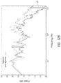
- FIGS. 4A and 4B are graphs that schematically illustrate possible examples of power generated by different embodiments of the pressure wave generators disclosed herein.
- FIG. 4C is a graph of an acoustic power spectrum 1445 generated at multiple frequencies.
- FIG. 5 is a schematic cross-sectional side view of a coupling member having a fluid inlet passing therethrough.
- FIG. 6 is a schematic cross-sectional side view of a coupling member having a fluid inlet and a fluid outlet passing therethrough.
- FIG. 7A is a schematic cross-sectional side view of a coupling member having a fluid inlet, a fluid outlet, and a vent configured to regulate a pressure inside the chamber and/or tooth.
- FIG. 7B is a schematic cross-sectional side view of a plurality of pressure wave generators coupled with a coupling member.
- FIG. 8A is a schematic side cross-sectional view of a coupling member attached or coupled to a tooth by way of a locking tooth seal.
- FIG. 8B is a schematic side cross-sectional view of a coupling member having a curved distal end portion shaped to mate with a curved surface of a tooth seal.
- FIG. 8C is a schematic side cross-sectional view of a coupling member having an alignment feature comprising a mating tube sized and shaped to fit through an access opening formed in the tooth.
- FIG. 9A is a schematic side cross-sectional view of a coupling member and a pressure wave generator comprising a liquid jet device.
- FIG. 9B is a schematic side cross-sectional view of a coupling member and a pressure wave generator comprising a light emitting element.
- FIG. 9C is a schematic side cross-sectional view of a coupling member and a pressure wave generator comprising a vibrating mechanical element.
- FIG. 9D is a schematic side cross-sectional view of a coupling member 3 and a pressure wave generator comprising a stirring element.
- FIG. 10A is a side cross-sectional view of a coupling member having a pressure wave generator comprising a fluid inlet configured to generate a rotational fluid motion in a chamber of a coupling member.
- FIG. 10B is a side cross-sectional view of a coupling member having a pressure wave generator comprising a liquid jet device configured to generate a rotational fluid motion in a chamber of the coupling member.
- FIG. 10C is a side cross-sectional view of a coupling member having a pressure wave generator comprising a light emitting device configured to generate a rotational fluid motion in a chamber of the coupling member.
- FIG. 10D is a side cross-sectional view of a coupling member having a pressure wave generator substantially aligned with a central axis Z of the root canal.
- FIG. 10E is a side cross-sectional view of a coupling member having a first pressure wave generator and a second pressure wave generator.
- FIG. 10F is a schematic top view of a pressure wave generator at least partially disposed in a chamber and configured to generate swirl in the chamber.
- FIG. 10G is a schematic top view of multiple pressure wave generators at least partially disposed in a chamber and configured to generate counter-swirl fluid motion in the chamber.
- FIG. 11A is a schematic diagram of an experimental setup designed to measure the power output of various tooth cleaning devices.
- FIG. 11B is a plot of the voltage (in volts) output by the hydrophone over time (in seconds) for each device tested.
- FIG. 12A illustrates images of root canals that compare the use of non-degassed liquid and degassed liquid in the disclosed pressure wave generators.
- FIG. 12B is a plot comparing the power output for techniques using non-degassed and degassed liquids.
- FIG. 13 is a plot comparing the rates of tissue dissolution (in units of % per second) for Applicant's device versus other devices, for different treatment fluids and compositions.
- FIGS. 14A-14B are plots relating to the pressure measured at or near the apical opening of the root canal during treatment.
- FIG. 14C is a plot of the mass of material extruded through the apex for various simulated peri-apical pressures for Applicant's system and for various needles
- the present disclosure describes apparatus, methods, and compositions for performing dental and/or endodontic procedures.
- Various embodiments disclosed herein can effectively and safely remove unhealthy material from a treatment region of a tooth, e.g., from within the tooth and/or from outside surfaces of the tooth.
- the embodiments disclosed herein can remove unhealthy materials, such as unhealthy organic matter, inorganic matter, pulp tissue, caries, stains, calculus, plaque, biofilm, bacteria, pus, decayed tooth matter, and food remnants from the treatment region without substantially damaging healthy dentin or enamel.
- the disclosed apparatus, methods, and compositions advantageously may be used with root canal cleaning treatments, e.g., to efficiently remove unhealthy or undesirable materials such as organic and/or inorganic matter from a root canal system and/or to disinfect the root canal system.
- Organic material includes organic substances typically found in healthy or diseased teeth or root canal systems such as, for example, soft tissue, pulp, blood vessels, nerves, connective tissue, cellular matter, pus, and microorganisms, whether living, inflamed, infected, diseased, necrotic, or decomposed.
- Inorganic matter includes calcified tissue and calcified structures, which are frequently present in the root canal system.
- the root canal can be filled with an obturation material (e.g., a flowable obturation material that can be hardened into a solid or semi-solid state, gutta percha or other solid or semi-solid materials) after treatment of the root canal.
- an obturation material e.g., a flowable obturation material that can be hardened into a solid or semi-solid state, gutta percha or other solid or semi-solid materials
- FIG. 1A is a schematic diagram of a system 1 that includes components capable of removing unhealthy or undesirable materials from a tooth 10 .
- the tooth 10 illustrated in FIG. 1A is a premolar tooth, e.g., a tooth located between canine and molar teeth in a mammal such as a human.
- the tooth 10 includes hard structural and protective layers, including a hard layer of dentin 16 and a very hard outer layer of enamel 17 .
- a pulp cavity 11 is defined within the dentin 16 .
- the pulp cavity 11 comprises one or more root canals 13 extending toward an apex 14 of each root 12 .
- the pulp cavity 26 and root canal 13 contain dental pulp, which is a soft, vascular tissue comprising nerves, blood vessels, connective tissue, odontoblasts, and other tissue and cellular components. Blood vessels and nerves enter/exit the root canal 13 through a tiny opening, the apical foramen or apical opening 15 , near a tip of the apex 14 of the root 12 .
- dental pulp which is a soft, vascular tissue comprising nerves, blood vessels, connective tissue, odontoblasts, and other tissue and cellular components. Blood vessels and nerves enter/exit the root canal 13 through a tiny opening, the apical foramen or apical opening 15 , near a tip of the apex 14 of the root 12 .
- tooth 10 illustrated herein is a premolar
- the embodiments disclosed herein can advantageously be used to treat any suitable type of tooth, including molars, canines, incisors, etc.
- the system 1 can be used to remove unhealthy materials (such as organic and inorganic matter) from an interior of the tooth 10 , e.g., from the root canal 13 of the tooth 10 .
- an endodontic access opening 18 can be formed in the tooth 10 , e.g., on an occlusal surface, a buccal surface, or a lingual surface.
- the access opening 18 provides access to a portion of a pulp cavity 11 of the tooth 10 .
- the system 1 can include a console 2 , a pressure wave generator 5 , and a coupling member 3 adapted to couple to the tooth 10 .
- the coupling member 3 can define a chamber 6 configured to retain fluid therein.
- One or more conduits 4 can electrically, mechanically, and/or fluidly connect the console 2 with the coupling member 3 and pressure wave generator 5 .
- the console 2 can include a control system and various fluid management systems configured to operate the pressure wave generator 5 during a treatment procedure.
- the system 1 can be used in cleaning procedures to clean substantially the entire root canal system.
- the system 1 can be used to fill substantially the entire root canal system with an obturation or filler material.
- the pressure wave generator 5 can generate pressure waves 23 of sufficient power and relatively low frequencies to produce fluid motion 24 in the chamber 6 —such that the pressure wave generators 5 disclosed herein can act as a fluid motion generator—and can generate pressure waves of sufficient power and relatively higher frequencies to produce surface effect cavitation on a dental surface, either inside or outside the tooth.
- the pressure wave generators 5 disclosed herein can act as fluid motion generators to generate large-scale or bulk fluid motion 24 in or near the tooth 10 , and can also generate smaller-scale fluid motion at higher frequencies.
- the fluid motion 24 in the chamber 6 can generate induced fluid motion such as vortices 75 , swirl 76 (see FIG. 2B ), etc. in the tooth 10 and root canal 13 that can clean and/or fill the canal 13 .
- FIG. 1B is a schematic diagram of a system 1 that includes components capable of removing unhealthy or undesirable material from a treatment region 91 on an exterior surface of the tooth.
- the system 1 can include a coupling member 3 and a pressure wave generator 5 .
- the coupling member 3 can communicate with a console 2 by way of one or more conduits 4 .
- the coupling member 3 is coupled to a treatment region 91 on an exterior surface of the tooth 10 .
- the system 1 of FIG. 1B can be activated to clean an exterior surface of the tooth 10 , e.g., a carious region of the tooth 10 .
- the system 1 can be activated to fill a treated region on the exterior surface of the tooth 10 .
- fluid motion 24 can be generated in the coupling member 3 and chamber, which can act to clean and/or fill the treatment region 91 of the tooth 10 .
- FIG. 2A is a schematic side cross-sectional view of a coupling member 3 coupled to a tooth 10 and a pressure wave generator 5 having a distal end portion 25 disposed in a chamber 6 outside the tooth 10 .
- the coupling member 3 can be adapted to couple to the tooth 10 to provide a stable platform during the dental procedure.
- the coupling member 3 can define or include a chamber 6 configured to retain fluid 22 .
- the chamber 6 can be substantially filled with a fluid 22 o provide a propagation medium upon and/or through which the pressure wave generator 5 acts.
- the fluid 22 can be a treatment fluid in various cleaning treatments to substantially clean a treatment region of the tooth (such as in root canal treatments, treatments of carious regions, treatments of plaque and other unhealthy deposits).
- the fluid 22 can comprise a flowable obturation material having a flowable state that can be hardened into a solid state, and the pressure wave generator 5 can be activated to substantially fill or obturate the treatment region.
- the obturation material once it fills the treatment region, can be hardened by a catalyst, be it heat, light, or chemical.
- the chamber 6 and coupling member 3 can prevent fluid 22 and/or waste materials from leaving the tooth 10 .
- the coupling member 3 can also be configured to regulate fluid pressure in the tooth 10 such that liquid can flow out from the chamber 6 if pressure rises above a predetermined threshold.
- the coupling member 3 comprises a distal portion 21 of a handpiece 20 (see, e.g., FIG. 3B ).
- the distal portion 21 of the handpiece 20 can be shaped to define walls enclosing the chamber 6 .
- the coupling member 3 can be applied to the tooth 10 with a mechanical clasp or clamp, a dental adhesive, or by pressure applied by the patient by biting on the coupling member 3 .
- a separate cap or fluid retainer can be removably coupled to the distal portion 21 of the handpiece 20 .
- a clinician can apply the coupling member 3 to the tooth 10 .
- the clinician can apply the coupling member 3 over the access opening 18 .
- the clinician can secure the coupling member 3 to the tooth 10 by way of a tooth seal 26 .
- one or more alignment features can be applied to align the coupling member 3 to the treatment region of the tooth 10 (see, e.g., FIGS. 8A-8C ).
- the coupling member 3 can be attached to the tooth 10 in a manner that permits the clinician to rotate or otherwise orient the coupling member 3 and pressure wave generator 5 at a desired orientation relative to the tooth 10 (see, e.g., FIG. 8B ).
- the clinician can apply the coupling member 3 and pressure wave generator 5 to an exterior surface of the tooth 10 .
- the clinician can apply the coupling member 3 over a carious region formed near an outer surface of the tooth 10 .
- the clinician or a user can apply the coupling member 3 over an exterior surface of the tooth 10 to remove undesirable dental deposits, such as plaque, calculus, biofilms, etc.
- the pressure wave generator 5 can be coupled with or integrally formed with the coupling member 3 .
- the pressure wave generator 5 can comprise an elongated member extending from the coupling member 3 through a portion of the chamber 6 .
- the distal end portion 25 of the pressure wave generator 5 can be disposed in the chamber 5 defined by the coupling member 3 .
- the distal end portion 25 of the pressure wave generator 5 can be disposed outside the tooth 10 , e.g., outside the pulp cavity 11 .
- the distal end portion 25 of the pressure wave generator 5 can extend into an interior space of the tooth 10 , e.g., the pulp cavity 11 .
- FIG. 2B is a schematic side cross-sectional view of a coupling member 3 coupled to a tooth 10 and a pressure wave generator 5 having a distal end portion 25 disposed inside the tooth 10 , e.g., inside a portion of the pulp cavity 11 .
- the distal end portion 25 of the pressure wave generator 5 can be submerged in treatment fluid retained in the chamber 6 by the coupling member 3 .
- the pressure wave generator 5 can be activated, and unhealthy materials (e.g., unhealthy organic matter, inorganic matter, pulp tissue, caries, stains, calculus, plaque, biofilm, bacteria, pus, decayed tooth matter, and food remnants) can be safely and efficiently removed from the tooth 10 .
- unhealthy materials e.g., unhealthy organic matter, inorganic matter, pulp tissue, caries, stains, calculus, plaque, biofilm, bacteria, pus, decayed tooth matter, and food remnants
- diseased pulp and other undesirable materials can be removed from the pulp cavity 11 and root canal 13 of the tooth 10 .
- the pressure wave generator 5 can clean treatment regions of the tooth 10 that are remote from the pressure wave generator 5 .
- the pressure wave generator can clean substantially the entire root canal 13 , including laterally-extending tubules and various small cracks and crevices that are formed in the tooth 10 .
- the pressure wave generators 5 disclosed herein can clean substantially the entire treatment region of the tooth. The pressure wave generators 5 disclosed herein can therefore improve patient outcomes by removing unhealthy materials from the entire treatment region, which reduces the risk of infection or recurrences of unhealthy material at the treatment region.
- the pressure wave generator 5 can fill or obturate the treatment region of the tooth (e.g., a cleaned root canal space, a cleaned carious region on an exterior surface of the tooth, etc.) after cleaning.
- the disclosed pressure wave generators 5 can substantially fill the entire root canal system, including the main canals, laterally-extending tubules, and various small cracks, spaces, crevices, etc.
- the improved obturation provided by the pressure wave generators 5 disclosed herein can improve patient outcomes by reducing the risk of infection from unobturated spaces in cleaned canals.
- the pressure wave generator 5 can clean and/or fill the tooth 10 by way of a combination of several different phenomena.
- the pressure wave generator 5 can generate pressure waves 23 that propagate through the fluid 22 and inside the tooth 10 , and the pressure wave generator 5 can also act as a fluid motion generator to generate a motion 24 of fluid 22 in the chamber 6 .
- the fluid motion 24 generated by the fluid motion generators disclosed herein can be induced by flowing the fluid across an access port of the chamber 6 and/or the coupling member 3 .
- the fluid 22 can be flowed across the access port in a direction substantially parallel to a plane of the access port and/or perpendicular to the central axis of the root canal 13 .
- the fluid motion 24 described in each embodiment disclosed herein can comprise rotational or non-rotational flow patterns in the chamber 6 .
- the fluid motion 24 can be laminar or turbulent. For example, in laminar fluid motions 24 , larger or bulk fluid motion may be generated. In turbulent fluid motions 24 , smaller fluid motions or perturbations can be generated.
- a combination of laminar and turbulent flow may be generated.
- the fluid flow 24 in the chamber and the induced flow (e.g., vortices, swirl, etc.) in the tooth can be generated in a substantially continuous manner or can be intermittent or periodic.
- the fluid motion 24 can comprise rotational motion, e.g., the fluid can rotate about an axis transverse to a central axis of the root canal 13 (see, e.g., FIG. 2A ).
- the fluid motion 24 can induce vortices 75 flowing about an axis substantially perpendicular to the central axis of the root canal 13 (see, e.g., FIG. 2A ).
- the fluid motion 24 can be generated about the central axis of the root canal 13 and can generate a swirl flow 76 that can propagate through the canal 13 (see, e.g., FIG. 2B ).
- the fluid motion 24 can comprise planar fluid flow, e.g., fluid flow that comprises planar wavefronts.
- the fluid motion 24 can comprise unsteady or chaotic flow.
- the pressure waves 23 can enhance the chemical reactions produced between treatment fluids and the unhealthy material to enable the detachment of unhealthy materials from the tooth 10 in a safe and efficient manner.
- the pressure wave generator 5 can be configured to induce acoustic cavitation throughout the tooth 10 , which can assist in removing unhealthy materials from larger spaces in the tooth, such as the main root canal 13 , as well as from extremely small spaces in the tooth 10 , such as tubules and various cracks and crevices that may be formed in the tooth 10 .
- the motion 24 of the fluid 22 can also improve the cleaning of the tooth 10 by refreshing the chemical reactants used in the fluid 22 , which can act to speed up the chemical reactions between the fluid 22 and the unhealthy materials in the tooth. Furthermore, the motion 24 of the fluid 22 can impart momentum in the tooth 10 that helps to dislodge the unhealthy or undesirable materials from the tooth 10 and to irrigate the dislodged materials out of the tooth 10 . As explained herein, the motion 24 of the fluid 22 can also reduce apical pressures at or near the apical opening 15 of the tooth 10 .
- the pressure waves 23 and motion 24 generated by the systems disclosed herein can improve patient outcomes as compared with other treatments by cleaning unhealthy materials from both large and small spaces of the tooth, and by enhancing the chemical reactions between the fluid 22 and the unhealthy materials to be removed from the tooth 10 .
- the systems and methods disclosed herein can clean the tooth with little or no discomfort to the patient.
- the embodiments disclosed herein can advantageously obturate or fill substantially the entire canal(s) and/or branch structures therefrom, as explained in greater detail below.
- the pressure wave generator 5 comprises one or more embodiments of the various apparatus described herein.
- the pressure wave generator 5 can include a liquid jet device.
- the liquid jet device comprises a positioning member (e.g., a guide tube) having a channel or lumen along which or through which a liquid jet can propagate.
- the distal end portion of the positioning member may include an impingement surface on which the liquid jet impinges and is deflected into jets or spray.
- the distal end portion of the positioning member may include one or more openings that permit the jet to interact with the fluid in the surrounding environment (e.g., fluid in the tooth chamber) and also permit the deflected liquid to exit the positioning member and interact with the surrounding environment and fluid 22 in the chamber 6 and/or tooth 10 .
- the result of these interactions can be the generation of pressure waves and fluid motion in the tooth 10 , which can at least partially clean the tooth 10 .
- the pressure wave generators 5 may act as fluid motion generators.
- the openings disposed at or near the distal end portion of the positioning member are submerged in the fluid 22 retained in the chamber 6 by the coupling member 3 .
- the pressure wave generator 5 may include a sonic, ultrasonic, or megasonic device (e.g., a sonic, ultrasonic, or megasonic paddle, horn, or piezoelectric transducer), a mechanical stirrer (e.g., a motorized propeller or paddle or rotating/vibrating/pulsating disk or cylinder), an optical system that can provides optical energy to the chamber 6 (e.g., an optical fiber that propagates laser light into the chamber 6 ), or any other device that can cause sufficient rotational fluid motion and acoustic waves to be generated in the tooth or in a propagation medium in the tooth (e.g., the fluid retained in a tooth chamber).
- a sonic, ultrasonic, or megasonic device e.g., a sonic, ultrasonic, or megasonic paddle, horn, or piezoelectric transducer
- a mechanical stirrer e.g., a motorized propeller or paddle or rotating/vibrating/puls
- the embodiments disclosed herein can advantageously remove undesirable or unhealthy materials from a tooth such that substantially all the unhealthy material is removed while inducing minimal or no discomfort and/or pain in the patient.
- the pressure wave generator 5 can induce various fluidic effects that interact with the unhealthy material to be removed, even when the pressure wave generator 5 is disposed at a position remote from the treatment region of the tooth, e.g., the region of the tooth that includes the unhealthy or undesirable material to be removed.
- the pressure wave generator 5 can impart energy to the fluid 22 that induces the relatively large-scale or bulk circulation or movement 24 of liquid in the chamber 6 and tooth 10 , and that also generates pressure waves 23 that propagate through the fluid 22 and tooth 10 .
- the generated fluid motion 24 and pressure waves 23 can magnify or enhance the properties of the fluid 22 to enhance cleaning of the tooth 10 .
- the pressure wave generator 5 can be used to obturate or fill the root canals and/or other treated regions of the tooth.
- the fluid 22 can comprise a treatment fluid that can be introduced into the tooth 10 and the chamber 6 to assist in removing unhealthy or undesirable materials from the tooth 10 .
- the treatment fluids can be selected based on the chemical properties of the fluids when reacting with the undesirable or unhealthy material to be removed from the tooth 10 .
- the treatment fluids disclosed herein can include any suitable fluid, including, e.g., water, saline, etc.
- tissue dissolving agents e.g., NaOCl or bleach
- disinfectants e.g., chlorhexidine
- fluoride therapy agents e.g., fluoride therapy agents
- EDTA ethylenediaminetetraacetic acid
- citric acid e.g., citric acid
- any other antibacterial, decalcifying, disinfecting, mineralizing, or whitening solutions may be used as well.
- the clinician can supply the various fluids to the tooth in one or more treatment cycles, and can supply different fluids sequentially or simultaneously.
- bleach-based solutions e.g., solutions including NaOCl
- a treatment solution comprises water or saline with 0.3% to 6% bleach (NaOCl).
- tissue dissolution and dental deposit removal in the presence of bleach may not occur when the bleach concentration is less than 1%.
- tissue dissolution and dental deposit removal can occur at smaller (or much smaller) concentrations.
- the clinician can supply an EDTA-based solution to remove undesirable or unhealthy calcified material from the tooth 10 .
- a smear layer may form on the walls of the canal 13 .
- the smear layer can include a semi-crystalline layer of debris, which may include remnants of pulp, bacteria, dentin, and other materials.
- Treatment fluids that include EDTA may be used to remove part or all of the smear layer, and/or calcified deposits on the tooth 10 .
- the clinician may supply a treatment fluid that comprises substantially water.
- the water can be used to assist in irrigating the tooth before, during, and/or after the treatment.
- the water can be supplied to remove remnants of other treatment fluids (e.g., bleach or EDTA) between treatment cycles.
- bleach has a pH that tends to be a base and because EDTA is an acid, it can be important to purge the tooth 10 and chamber 6 between bleach and EDTA treatments to avoid potentially damaging chemical reactions.
- the water can be supplied with a sufficient momentum to help remove detached materials that are disrupted during the treatment.
- the water can be used to convey waste material from the tooth 10 .
- chemicals and the concentrations of the chemicals can be varied throughout the procedure by the clinician and/or by the system to improve patient outcomes.
- the clinician can alternate between the use of water, bleach, and EDTA, in order to achieve the advantages associated with each of these chemicals.
- the clinician may begin with a water cycle to clean out any initial debris, then proceed with a bleach cycle to dissociate diseased tissue and bacteria from the tooth.
- a water cycle may then be used to remove the bleach and any remaining detached materials from the tooth 10 .
- the clinician may then supply EDTA to the tooth to remove calcified deposits and/or portions of a smear layer from the tooth 10 .
- Water can then be supplied to remove the EDTA and any remaining detached material from the tooth 10 before a subsequent bleach cycle.
- the clinician can continually shift between cycles of treatment fluid throughout the procedure.
- the above example is for illustrative purposes only. It should be appreciated that the order of the cycling of treatment liquids may vary in any suitable manner and order.
- the treatment fluids used in the embodiments disclosed herein can react chemically with the undesirable or unhealthy materials to dissociate the unhealthy materials from the healthy portions of the tooth 10 .
- the treatment fluids can also be used to irrigate waste fluid and/or detached or delaminated materials out of the tooth 10 .
- the treatment solution (including any suitable composition) can be degassed, which may improve cavitation and/or reduce the presence of gas bubbles in some treatments.
- the dissolved gas content can be less than about 1% by volume. Additional properties and characteristics of the treatment fluid 22 are presented in more detail herein in Section VII.
- a pressure wave generator 5 can remove unhealthy materials from a tooth by propagating pressure waves 23 through a propagation medium (e.g., the treatment fluid) to the treatment region, which can include one or more teeth and/or gums.
- a propagation medium e.g., the treatment fluid
- the pressure waves 23 remove undesirable materials are presented herein. Note that these principles, and the principles described above, may be generally applicable for each embodiment disclosed herein.
- cavitation may be induced by the generated pressure waves 23 .
- a liquid e.g., water or other treatment fluid
- acoustic cavitation may occur.
- the oscillation or the implosive collapse of small cavitation bubbles can produce localized effects, which may further enhance the cleaning process, e.g., by creating intense, small-scale localized heat, shock waves, and/or microjets and shear flows. Therefore, in some treatment methods, acoustic cavitation may be responsible for or involved in enhancing the chemical reactions, sonochemistry, sonoporation, soft tissue/cell/bacteria dissociation, delamination and breakup of biofilms.
- the pressure waves 23 may enhance the chemical reaction via agitation and/or sonochemistry.
- the pressure waves 23 can enhance the chemical effects that each composition has on the unhealthy material to be removed from the tooth.
- the generated pressure waves 23 can propagate so as to dissociate tissue throughout the entire tooth 10 , including in the dentinal tubules and throughout tiny cracks and crevices of the tooth 10 .
- the generated pressure waves 23 can propagate so as to remove the smear layer and/or calcified deposits from the tooth 10 , including in the tubules and/or in tiny cracks and crevices formed in the tooth 10 .
- the generated pressure waves 23 can propagate so as to flush and/or irrigate undesirable materials from the tooth, including in tubules and tiny cracks and crevices. Accordingly, the generated pressure waves 23 can enhance the removal of undesirable or unhealthy materials from the tooth 10 by magnifying the chemical effects of whatever treatment fluid composition is used during a particular treatment cycle.
- sonoporation which is the process of using pressure waves and/or the subsequent acoustic cavitation to modify the permeability of the bacterial cell plasma membrane, may also expedite the chemical reaction that removes the microorganisms from the tooth.
- generated pressure waves, and/or the subsequent acoustic cavitation of certain frequencies may result in cellular and bacterial rupture and death (e.g., lysis) as well as removal of decayed and weakened dentin and enamel.
- the cellular and bacterial rupture phenomenon may kill bacteria which might otherwise reinfect the gingival pockets and/or the oral cavity.
- Generated pressure waves and/or the subsequent acoustic cavitation may also loosen the bond of the structure of the unhealthy material (e.g., diseased tissue, calculus, biofilm, caries, etc.), and/or the pressure waves may dissociate the unhealthy material from the tooth 10 .
- pressure waves and/or acoustic cavitation may loosen the bond between the cells and the dentin and/or delaminate the tissue from the tooth.
- the pressure waves and/or the subsequent acoustic cavitation may act on decayed hard tissue (which may be relatively weak and loosely connected) through vibrations and/or shock waves, and/or the microjets created as a result of cavitation bubble implosion, to remove decayed hard tissue from other healthy portions of the tooth.
- bulk fluid motion 24 can enhance the cleaning of unhealthy material from a diseased tooth.
- the fluid motion 24 generated in the chamber 6 and/or tooth 10 can impart relatively large momentum to the tooth, which can help dissociate and irrigate unhealthy materials from the tooth.
- the fluid motion 24 can induce vortices 75 and/or swirl 76 in the tooth 10 that can result in negative pressures (or low positive pressures) near the apical opening 15 of the tooth 10 .
- the resulting negative pressures at the apical opening 15 can prevent or reduce an amount of material extruded through the apical opening 15 and into the jaw of the patient. By preventing or reducing the amount of extruded material, the risk of infection can be lowered or eliminated, and patient outcomes can be substantially improved.
- liquid circulation with a time scale comparable to (and preferably faster than) that of chemical reaction may help replenish the reactants at the chemical reaction front and/or may help to remove the reaction byproducts from the reaction site.
- the relatively large convective time scale which may relate to effectiveness of the convection process, can be adjusted and/or optimized depending on, e.g., the location and characteristics of the source of circulation.
- liquid circulation or other fluid motion 24 generally does not eliminate the diffusion process, which may still remain effective within a thin microscopic layer at the chemical reaction front.
- Liquid circulation can also cause a strong irrigation effect at the treatment site (e.g. removing diseased tissue deep in the canal 13 and/or tubules and small spaces and cracks of the tooth 10 ) and may therefore result in loosening and/or removing large and small pieces of debris from the treatment site.
- various properties can be adjusted to enhance bulk fluid motion and/or fluid circulation, e.g., fluid motion in the chamber 6 .
- the position of the pressure wave generator 5 relative to the location of the treatment site can be adjusted.
- the pressure wave generator 5 is disposed such that the pressure wave generator 5 passes a stream of liquid across the access opening 18 .
- the pressure wave generator 5 can be disposed to induce fluid motion 24 about an axis transverse to a central axis of the root canal 13 , which can generate vortices 75 that propagate throughout the canal 13 .
- the fluid motion 24 can be generated about the central axis of the root canal 13 , which can induce swirl motion 76 in the root canal 13 .
- the fluid flow 24 over the access port or access opening of the tooth 10 can be varied.
- the momentum of the fluid 24 can be varied to create the desired flow in the root canals 13 .
- the angle of the fluid flow 24 relative to the access port can be varied to control the apical pressure in the canals 13 , e.g., to induce apical pressures that are more positive, more negative, etc.
- the geometry of the space surrounding the pressure wave generator 5 and treatment site e.g., the geometry of the coupling member 3
- circulation may be affected by the viscosity of the fluid 22 and/or the mechanism of action of the pressure wave generator 5 .
- the pressure wave generator 5 such as a jet of liquid ejected through an inlet opening, a stirrer such as a propeller or a vibrating object, etc., can be selected to enhance fluid motion of the treatment fluid.
- the input power of the source of liquid circulation can also be adjusted, such as the source of a pump that drives a liquid jet in some embodiments.
- the pressure wave generators 5 disclosed herein can enhance other dental and endodontic procedures. For example, after cleaning a tooth (e.g., a root canal inside the tooth, a carious region on or near an exterior surface of the tooth, etc.), the treatment region can be filled with an obturation or filler material.
- the filler material can be supplied to the treatment region as a flowable material and can be hardened to fill the treatment region (e.g., the cleaned root canal or carious region, etc.).
- a pressure wave generator 5 can be activated to supply the obturation material throughout the treatment region.
- the pressure wave generator can supply the flowable obturation material into the tooth and root canal.
- the large-scale fluid movement generated by the pressure wave generator 5 can assist in propagating the obturation material throughout relatively large spaces, such as the main root canal or canals.
- the pressure wave generator 5 may introduce sufficient momentum such that the flowable obturation material propagates throughout the canal space without introducing additional instrumentation into the tooth.
- the bulk fluid motion of the obturation material into the canal may be such that the clinician may not need to or desire to enlarge the canals. By reducing or eliminating canal enlargement, patient outcomes and pain levels can be improved.
- the bulk fluid motion of the flowable obturation material can be generated at relatively low frequencies produced by the pressure wave generator.
- the pressure wave generators 5 disclosed herein can generate higher frequency perturbations to propagate the obturation material into smaller cracks, spaces, and crevices in the tooth.
- higher-frequency effects such as acoustic cavitation, can assist in propagating the filler material throughout the tooth.
- the pressure wave generators disclosed herein can enhance the filling of a treatment region such as a root canal, carious region of the tooth, etc.
- the obturation material can be propagated at a distance such that it flows into the treatment region from a remote pressure wave generator 5 (which may be disposed outside the tooth).
- Large-scale or bulk fluid motion of the obturation material can fill larger canal spaces or other treatment regions without further enlargening the treatment region.
- Smaller-scale and/or higher frequency agitation by the pressure wave generator 5 can propagate the obturation material into smaller cracks and spaces of the tooth.
- a pressure wave generator 5 can be used in various disclosed embodiments to clean a tooth 10 , e.g., from interior or exterior portions of the tooth 10 and/or gums. In other embodiments, the pressure wave generator 5 can be used to fill or obturate a cleaned root canal or other treatment region of the tooth 10 . In some embodiments, the pressure wave generator 5 can comprise an elongated member having an active distal end portion 25 . The active distal end portion 25 can be activated by a user to apply energy to the treatment tooth 10 to remove unhealthy or undesirable material from the tooth 10 .
- the disclosed pressure wave generators 5 can be configured to generate pressure waves 23 and fluid motion 24 with energy sufficient to clean undesirable material from a tooth 10 .
- the pressure wave generator 5 can be a device that converts one form of energy into acoustic waves and bulk fluid motion (e.g., rotational motion) within the fluid 22 .
- the pressure wave generator 5 can induce, among other phenomena, both pressure waves and bulk fluid dynamic motion in the fluid 22 (e.g., in the chamber 6 ), fluid circulation, turbulence, vortices and other conditions that can enable the cleaning of the tooth.
- the pressure wave generator 5 disclosed in each of the figures described herein may be any suitable type of pressure wave generator.
- the pressure wave generator 5 can be used to clean the tooth 10 by creating pressure waves that propagate through the fluid 22 , e.g., through treatment fluid at least partially retained in the chamber 6 .
- the pressure wave generator 5 may also create cavitation, acoustic streaming, turbulence, etc.
- the pressure wave generator 5 can generate pressure waves or acoustic energy having a broadband power spectrum (see, e.g., FIGS. 4A-4C ).
- the pressure wave generator 5 can generate pressure waves at multiple different frequencies, as opposed to only one or a few frequencies. Without being limited by theory, it is believed that the generation of power at multiple frequencies can help to remove various types of organic and/or inorganic materials that have different material or physical characteristics at various frequencies.
- the pressure wave generator 5 (e.g., high-speed liquid jet, ultrasonic transducer, a laser fiber, etc.) can be placed at the desired treatment location in or on the tooth 10 .
- the pressure wave generator 5 can create pressure waves 23 and fluid motion 24 within the fluid 22 inside a substantially-enclosed chamber 6 .
- the pressure wave generator 5 can be sufficiently strong to remove unhealthy materials such as organic and/or inorganic tissue from teeth 10 .
- the pressure wave generator 5 can be configured to avoid substantially breaking down or harming natural dentin and/or enamel.
- the pressure wave generator 5 can comprise a liquid jet device.
- the liquid jet can be created by passing high pressure liquid through an orifice.
- the liquid jet can create pressure waves within the treatment liquid.
- the pressure wave generator 5 comprises a coherent, collimated jet of liquid.
- the jet of liquid can interact with liquid in a substantially-enclosed volume (e.g., the chamber and/or the mouth of the user) and/or an impingement member to create the acoustic waves.
- the interaction of the jet and the treatment fluid, as well as the interaction of the spray which results from hitting the impingement member and the treatment fluid may assist in creating cavitation and/or other acoustic effects to clean the tooth.
- the liquid jet device can comprise a positioning member (e.g., a guide tube) having a channel or lumen along which or through which a liquid jet can propagate.
- the distal end portion of the positioning member can include one or more openings that permit the deflected liquid to exit the positioning member and interact with the surrounding environment in the chamber 6 or tooth 10 .
- the openings disposed at or near the distal end portion of the positioning member can be submerged in liquid that can be at least partially enclosed in the chamber 6 attached to or enclosing a portion of the tooth 10 .
- the liquid jet can pass through the guide tube and can impact an impingement surface.
- the passage of the jet through the surrounding treatment fluid and impact of the jet on the impingement surface can generate the acoustic waves in some implementations.
- the flow of the submerged portion of the liquid jet may generate a cavitation cloud within the treatment fluid.
- the creation and collapse of the cavitation cloud may, in some cases, generate a substantial hydroacoustic field in or near the tooth. Further cavitation effects may be possible, including growth, oscillation, and collapse of cavitation bubbles.
- bulk fluid motion such as rotational flow, may be induced.
- the induced rotational flow can enhance the cleaning process by removing detached material and replenishing reactants for the cleaning reactions. These (and/or other) effects may lead to efficient cleaning of the tooth.
- FIG. 3A is a block diagram that schematically illustrates an embodiment of a system 38 adapted to generate a high-velocity jet 60 of fluid for use in dental procedures.
- the system 38 comprises a motor 40 , a motor controller 54 , a fluid source 44 , a pump 46 , a pressure sensor 48 , a system controller 51 , a user interface 53 , and a handpiece 20 that can be operated by a dental practitioner to direct the jet 60 toward desired locations in a patient's mouth.
- the pump 46 can pressurize fluid received from the fluid source 44 .
- the pump 46 may comprise a piston pump in which the piston is actuatable by the motor 40 .
- the motor 40 can be controlled by way of the motor controller 54 .
- the high-pressure liquid from the pump 46 can be fed to the pressure sensor 48 and then to the handpiece 20 , for example, by a length of high-pressure tubing 49 .
- the pressure sensor 48 may be used to sense the pressure of the liquid and communicate pressure information to the system controller 51 .
- the system controller 51 can use the pressure information to make adjustments to the motor 40 and/or the pump 46 to provide a target pressure for the fluid delivered to the handpiece 20 .
- the system controller 51 may signal the motor 40 to drive the piston more rapidly or more slowly, depending on the pressure information from the pressure sensor 48 .
- the pressure of the liquid that can be delivered to the handpiece 20 can be adjusted within a range from about 500 psi to about 50,000 psi (1 psi is 1 pound per square inch and is about 6895 Pascal (Pa)). In certain embodiments, it has been found that a pressure range from about 2,000 psi to about 15,000 psi produces jets that are particularly effective for endodontic treatments. In some embodiments, the pressure is about 10,000 psi.
- the fluid source 44 may comprise a fluid container (e.g., an intravenous bag) holding any of the treatments fluids described herein.
- the treatment fluid may be degassed, with a dissolved gas content less than normal (e.g., non-degassed) fluids.
- treatment fluids include sterile water, a medical-grade saline solution, an antiseptic or antibiotic solution (e.g., sodium hypochlorite), a solution with chemicals or medications, or any combination thereof. More than one fluid source may be used. In certain embodiments, it is advantageous for jet formation if the liquid provided by the fluid source 44 is substantially free of dissolved gases, which may reduce the effectiveness of the jet and the pressure wave generation.
- the fluid source 44 comprises degassed liquid such as, e.g., degassed distilled water.
- a bubble detector (not shown) may be disposed between the fluid source 44 and the pump 46 to detect bubbles in the liquid and/or to determine whether liquid flow from the fluid source 44 has been interrupted or the container has emptied.
- degassed fluids may be used.
- the bubble detector can be used to determine whether small air bubbles are present in the fluid that might negatively impact jet formation or acoustic wave propagation.
- a filter or de-bubbler (not shown) can be used to remove small air bubbles from the liquid.
- the liquid in the fluid source 44 may be at room temperature or may be heated and/or cooled to a different temperature.
- the liquid in the fluid source 44 can be chilled to reduce the temperature of the high velocity jet 60 generated by the system 38 , which may reduce or control the temperature of the fluid inside a tooth 10 .
- the liquid in the fluid source 44 can be heated, which may increase the rate of chemical reactions that may occur in the tooth 10 during treatment.
- the handpiece 20 can be configured to receive the high pressure liquid and can be adapted at a distal end to generate a high-velocity beam or jet 60 of liquid for use in dental procedures.
- the system 38 may produce a coherent, collimated jet of liquid.
- the handpiece 20 may be sized and shaped to be maneuverable in the mouth of a patient so that the jet 60 may be directed toward or away from various portions of the tooth 10 .
- the handpiece 20 comprises a distal housing or coupling member that can be coupled to the tooth 10 .
- the system controller 51 may comprise a microprocessor, a special or general purpose computer, a floating point gate array, and/or a programmable logic device.
- the system controller 51 may be used to control safety of the system 38 , for example, by limiting system pressures to be below safety thresholds and/or by limiting the time that the jet 60 is permitted to flow from the handpiece 20 .
- the system 38 may also include a user interface 53 that outputs relevant system data or accepts user input (e.g., a target pressure).
- the user interface 53 comprises a touch screen graphics display.
- the user interface 53 may include controls for a dental practitioner to operate the liquid jet apparatus.
- the controls can include a foot switch to actuate or deactuate the jet.
- the motor 40 , motor controller 54 , pump 46 , fluid source 44 , pressure sensor 48 , system controller 51 , and user interface 53 can be integrated in the console 2 illustrated schematically in FIGS. 1A-1B .
- the system 38 may include additional and/or different components and may be configured differently than shown in FIG. 3A .
- the system 38 may include an aspiration pump that is coupled to the handpiece 20 (or an aspiration cannula) to permit aspiration of organic matter from the mouth or tooth 10 .
- the system 38 may comprise other pneumatic and/or hydraulic systems adapted to generate the high-velocity beam or jet 60 .
- a pressure wave generator and/or pressure wave generator that includes a liquid jet device may be found at least in ⁇ [0045]-[0050], [0054]-[0077] and various other portions of U.S. Patent Publication No. US 2011/0117517, published May 19, 2011, and in ⁇ [0136]-[0142] and various other portions of U.S. Patent Publication No. US 2012/0237893, published Sep. 20, 2012, each of which is incorporated by reference herein in its entirety and for all purposes.
- a pressure wave generator can be any physical device or phenomenon that converts one form of energy into acoustic waves within the treatment fluid and that induces rotational fluid motion in the chamber 6 and/or tooth 10 .
- Many different types of pressure wave generators (or combinations of pressure wave generators) are usable with embodiments of the systems and methods disclosed herein.
- Mechanical energy pressure wave generators can also include rotating objects, e.g. miniature propellers, eccentrically-confined rotating cylinders, a perforated rotating disk, etc. These types of pressure wave generators can also include vibrating, oscillating, or pulsating objects such as sonication devices that create pressure waves via piezoelectricity, magnetostriction, etc. In some pressure wave generators, electric energy transferred to a piezoelectric transducer can produce acoustic waves in the treatment fluid. In some cases, the piezoelectric transducer can be used to create acoustic waves having a broad band of frequencies.
- An electromagnetic beam of radiation (e.g., a laser beam) can propagate energy into a chamber, and the electromagnetic beam energy can be transformed into acoustic waves as it enters the treatment fluid.
- the laser beam can be directed into the chamber 6 as a collimated and coherent beam of light.
- the collimated laser beam can be sufficient to generate pressure waves as the laser beam delivers energy to the fluid.
- the laser beam can be focused using one or more lenses or other focusing devices to concentrate the optical energy at a location in the treatment fluid. The concentrated energy can be transformed into pressure waves sufficient to clean the undesirable materials.
- the wavelength of the laser beam or electromagnetic source can be selected to be highly absorbable by the treatment fluid in the chamber or mouth (e.g., water) and/or by the additives in the treatment fluid (e.g., nanoparticles, etc.).
- the electromagnetic energy may be absorbed by the fluid (e.g., water) in the chamber, which can generate localized heating and pressure waves that propagate in the fluid.
- the pressure waves generated by the electromagnetic beam can generate photo-induced or photo-acoustic cavitation effects in the fluid.
- the localized heating can induce rotational fluid flow in the chamber 6 and/or tooth 10 that further enhances cleaning of the tooth 10 (see, e.g., FIG. 10C ).
- the electromagnetic radiation from a radiation source can be propagated to the chamber by an optical waveguide (e.g., an optical fiber), and dispersed into the fluid at a distal end of the waveguide (e.g., a shaped tip of the fiber, e.g., a conically-shaped tip).
- a radiation source e.g., a laser
- an optical waveguide e.g., an optical fiber
- dispersed into the fluid at a distal end of the waveguide e.g., a shaped tip of the fiber, e.g., a conically-shaped tip.
- the radiation can be directed to the chamber by a beam scanning system.
- the wavelength of the electromagnetic energy may be in a range that is strongly absorbed by water molecules.
- the wavelength may in a range from about 300 nm to about 3000 nm.
- the wavelength is in a range from about 400 nm to about 700 nm, about 700 nm to about 1000 nm (e.g., 790 nm, 810 nm, 940 nm, or 980 nm), in a range from about 1 micron to about 3 microns (e.g., about 2.7 microns or 2.9 microns), or in a range from about 3 microns to about 30 microns (e.g., 9.4 microns or 10.6 microns).
- the electromagnetic energy can be in the ultraviolet, visible, near-infrared, mid-infrared, microwave, or longer wavelengths.
- the electromagnetic energy can be pulsed or modulated (e.g., via a pulsed laser), for example with a repetition rate in a range from about 1 Hz to about 500 kHz.
- the pulse energy can be in a range from about 1 mJ to about 1000 mJ.
- the pulse width can be in a range from about 1 ⁇ s to about 500 ⁇ s, about 1 ms to about 500 ms, or some other range.
- nanosecond pulsed lasers can be used with pulse rates in a range from about 100 ns to about 500 ns.
- the foregoing are non-limiting examples of radiation parameters, and other repetition rates, pulse widths, pulse energies, etc. can be used in other embodiments.
- the laser can include one or more of a diode laser, a solid state laser, a fiber laser, an Er:YAG laser, an Er:YSGG laser, an Er,Cr:YAG laser, an Er,Cr:YSGG laser, a Ho:YAG laser, a Nd:YAG laser, a CTE:YAG laser, a CO 2 laser, or a Ti:Sapphire laser.
- the source of electromagnetic radiation can include one or more light emitting diodes (LEDs).
- the electromagnetic radiation can be used to excite nanoparticles (e.g., light-absorbing gold nanorods or nanoshells) inside the treatment fluid, which may increase the efficiency of photo-induced cavitation in the fluid.
- the treatment fluid can include excitable functional groups (e.g., hydroxyl functional groups) that may be susceptible to excitation by the electromagnetic radiation and which may increase the efficiency of pressure wave generation (e.g., due to increased absorption of radiation).
- excitable functional groups e.g., hydroxyl functional groups
- radiation having a first wavelength can be used (e.g., a wavelength strongly absorbed by the liquid, for instance water) followed by radiation having a second wavelength not equal to the first wavelength (e.g., a wavelength less strongly absorbed by water) but strongly absorbed by another element, e.g. dentin, or nanoparticles added to solution.
- the first wavelength may help create bubbles in the fluid
- the second wavelength may help disrupt the tissue.
- the electromagnetic energy can be applied to the chamber 6 for a treatment time that can be in a range from about one to a few seconds up to about one minute or longer.
- a treatment procedure can include one to ten (or more) cycles of applying electromagnetic energy to the tooth.
- a fluid can circulate or otherwise move in the chamber during the treatment process, which advantageously may inhibit heating of the tooth 10 (which may cause discomfort to the patient).
- the movement or circulation of treatment fluid e.g., water with a tissue dissolving agent
- movement of the treatment fluid can increase the effectiveness of the cleaning (as compared to a treatment with little or no fluid circulation).
- electromagnetic energy can be added to other fluid motion generation modalities.
- electromagnetic energy can be delivered to a chamber in which another pressure wave generator (e.g., a liquid jet) is used to generate the acoustic waves.
- another pressure wave generator e.g., a liquid jet
- Acoustic energy (e.g., ultrasonic, sonic, audible, and/or lower frequencies) can be generated from electric energy transferred to, e.g., an ultrasound or other transducer or an ultrasonic tip (or file or needle) that creates acoustic waves in the treatment fluid.
- the ultrasonic or other type of acoustic transducer can comprise a piezoelectric crystal that physically oscillates in response to an electrical signal or a magnetostrictive element that converts electromagnetic energy into mechanical energy.
- the transducer can be disposed in the treatment fluid, for example, in the fluid inside the chamber. As explained herein with respect to FIGS.
- ultrasonic or other acoustic devices used with the embodiments disclosed herein are preferably broadband and/or multi-frequency devices.
- ultrasonic or other acoustic devices used with the disclosed embodiments preferably have broadband characteristics similar to those of the power spectra of FIGS. 4A-4B (acoustic power of a liquid jet device).
- a pressure wave generator 5 can be placed at a desired location with respect to the tooth 10 .
- the pressure wave generator 5 creates pressure waves within the fluid 22 inside the chamber 6 (the generation of acoustic waves may or may not create or cause cavitation).
- the acoustic or pressure waves 23 propagate throughout the fluid 22 inside the chamber 6 , with the fluid 22 in the chamber 6 serving as a propagation medium for the pressure waves 23 .
- the pressure waves 23 can also propagate through tooth material (e.g., dentin). It is believed, although not required, that as a result of application of a sufficiently high-intensity acoustic wave, acoustic cavitation may occur.
- the collapse of cavitation bubbles may induce, cause, or be involved in a number of processes described herein such as, e.g., sonochemistry, tissue dissociation, tissue delamination, sonoporation, and/or removal of calcified structures.
- the pressure wave generator can be configured such that the acoustic waves (and/or cavitation) do not substantially break down natural dentin in the tooth 110 .
- the acoustic wave field by itself or in addition to cavitation may be involved in one or more of the abovementioned processes.
- the pressure wave generator 5 generates primary cavitation, which creates acoustic waves, which may in turn lead to secondary cavitation.
- the secondary cavitation may be weaker than the primary cavitation and may be non-inertial cavitation.
- the pressure wave generator 5 generates acoustic waves directly, which may lead to secondary cavitation.
- the energy source that provides the energy for the pressure wave generator 5 can be located outside the handpiece 20 , inside the handpiece 20 , integrated with the handpiece 20 , etc.
- pressure wave generators e.g., which may comprise a pressure wave generator
- pressure wave generators may be suitable for use with the embodiments disclosed herein may be found, e.g., in ⁇ [0191]-[0217], and various other portions of U.S. Patent Publication No. US 2012/0237893, published Sep. 20, 2012, which is incorporated by reference herein for all purposes.
- a fluid inlet can be disposed at a distal portion of a handpiece and/or can be coupled to a fluid platform in some arrangements.
- the fluid inlet can be configured to create movement of the fluid in a chamber 6 , turbulence in the fluid in the chamber, fluid motion 24 of the fluid 22 in the chamber 6 and/or produce other dynamics in the fluid in the chamber 6 r .
- the fluid inlet can inject fluid into or on the tooth to be treated.
- mechanical stirrers and other devices can be used to enhance fluid motion and cleaning.
- the fluid inlet can improve the circulation of the treatment fluid in a chamber, which can enhance the removal of unhealthy materials from the tooth 10 .
- faster mechanisms of reactant delivery such as “macroscopic” liquid circulation may be advantageous in some of the embodiments disclosed herein.
- multiple pressure wave generators can be disposed in or on the chamber 6 .
- each of the multiple pressure wave generators can be configured to propagate acoustic waves at a different frequency or range of frequencies. For example, different acoustic frequencies can be used to remove different types of materials.
- the multiple pressure wave generators can be activated simultaneously and/or sequentially in various arrangements.
- the coupling members 3 disclosed herein can be adapted to couple or orient the pressure wave generator 5 relative to the tooth 10 .
- the coupling member 3 can be configured to retain fluid 22 in a treatment chamber 6 .
- the coupling member 3 can be coupled to or formed with a distal portion 21 of the handpiece 20 .
- the coupling member 3 can include or define the chamber 6 configured to retain fluid 22 .
- Liquid can be introduced into the chamber 6 through a fluid inlet connected to, or disposed in or on, the handpiece 20 . Waste treatment liquid can be removed through the coupling member 3 by way of a fluid outlet and further into the handpiece 20 .
- the coupling member 3 may be configured to cover a portion of a tooth, a whole surface of the tooth, and/or multiple teeth.
- the coupling member 3 can be applied to the tooth 10 with a mechanical clasp or clamp, a dental adhesive, or by pressure applied by the patient by biting on the coupling member 3 .
- a separate cap or fluid retainer can be removably coupled to the distal portion 21 of the handpiece 20 .
- coupling members 3 may be similar to those of fluid retainers, flow restrictors or caps disclosed, e.g., in ⁇ [0052]-[0053], [0115]-[0117] and various other portions of U.S. Patent Publication No. US 2011/0117517, published May 19, 2011, and in ⁇ [0040]-[0043], [0170]-[01 [0293]-[0299], [0316]-[0319] and various other portions of U.S. Patent Publication No. US 2012/0237893, published Sep. 20, 2012, each of which is incorporated by reference herein for all purposes.
- the coupling member 3 can also include various components that enhance aspiration and irrigation before, during, and/or after the treatment procedure.
- fluid 22 can enter the chamber 6 via a fluid inlet, such as a treatment liquid inflow conduit.
- the fluid inlet can pass through or along the handpiece 20 .
- the amount of liquid entering the at least partially enclosed chamber 6 can be substantially the same as the amount of liquid leaving chamber 6 through the fluid outlet.
- the fluid inlet can be driven by a pump, which can be controlled by the console 2 .
- the fluid inlet can be the same as the pressure wave generator 5 in some embodiments, such as in embodiments that employ a liquid jet device.
- fluid inlets that may be suitable for use with the embodiments disclosed herein may be found, e.g., in ⁇ [0075]-[0078] and various other portions of U.S. Patent Publication No. US 2012/0237893, published Sep. 20, 2012, which is incorporated by reference herein for all purposes.
- the coupling member 3 can also have a fluid outlet, e.g., an outflow conduit to transfer liquid out of the chamber 6 during the procedure.
- waste treatment liquid may be allowed to spill directly into the patient's mouth.
- waste treatment liquid (as well as removed material and byproduct gases) can be transferred through the fluid outlet, which can pass through or along the handpiece 20 .
- the fluid outlet can be active or passive. In the case of a passive fluid outlet, the waste treatment liquid may move through the fluid outlet due to capillary forces, gravity, or because of a slight overpressure created in the enclosed chamber 6 .
- the waste liquid can be transferred using a pump, suction, or other device that draws liquid out through the outlet.
- the fluid outlet is connected to the suction system and/or vacuum lines in the clinician's office.
- the inlet and outlet can be adjusted to maintain a balanced amount of fluid in coupling member 3 . Additional details of fluid outlets that may be suitable for use with the embodiments disclosed herein may be found, e.g., in ⁇ [0079]-[0081] and various other portions of U.S. Patent Publication No. US 2012/0237893, published Sep. 20, 2012, which is incorporated by reference herein for all purposes.
- the coupling member 3 can also include one or more vents to regulate pressure of the fluid 22 .
- the vents can be disposed in a portion of the handpiece 20 in some arrangements, such as along a waste line or fluid outlet.
- the vents can take the form of a permeable or semi-permeable material (e.g., a sponge), openings, pores, or holes, etc. Additional details of vents that may be suitable for use with the embodiments disclosed herein may be found, e.g., in ⁇ [0071]-[0073], [0082]-[0086], [0177]-[0194] and various other portions of U.S. Patent Publication No. US 2012/0237893, published Sep. 20, 2012, which is incorporated by reference herein for all purposes.
- the systems disclosed herein can include a handpiece 20 .
- the handpiece 20 can be configured to apply the coupling member 3 to the tooth 10 and/or to position the pressure wave generator 5 relative to the treatment site. Treatment liquids can be transferred into and out of the chamber 6 by way of the handpiece 20 .
- the handpiece 20 can provide the operator, user or clinician with a handheld device to hold during the procedure.
- the handpiece 20 can include user-friendly grips and a user-friendly shape to grasp.
- the clinician can manipulate the handpiece 20 to accurately position the coupling member 3 and/or pressure wave generator 5 at a desired position on the tooth 10 .
- the handpiece 20 can allow the clinician to move or rotate the coupling member 3 and pressure wave generator 5 during the procedure so as to dispose the pressure wave generator 5 at a desirable position relative to the treatment region in the tooth 10 .
- the handpiece 20 can also provide a device for the operator to clamp or attach to the tooth 10 such that the handpiece 20 does not require substantial user intervention during the procedure.
- the handpiece 20 can be disposable (e.g., single-use), or the handpiece 20 can be reusable. In one embodiment, the handpiece 20 is disposable, but the pressure wave generator 5 is reusable.
- the handpiece 20 can be formed of any suitable material. In some embodiments, the handpiece 20 can be formed of a plastic material. In other embodiments, the handpiece 20 can be formed of a metal. Additional details of handpieces that may be suitable for use with the embodiments disclosed herein may be found, e.g., in ⁇ [0107], [0138]-[0142], [0156]-[0161] and various other portions of U.S. Patent Publication No. US 2012/0237893, published Sep. 20, 2012, which is incorporated by reference herein for all purposes.
- FIG. 3B is a schematic side view illustrating an embodiment of a handpiece 20 comprising an embodiment of a guide tube 27 for delivery of a liquid jet to a portion of a tooth 10 .
- the handpiece 20 comprises an elongated tubular barrel 29 having a proximal end 31 that is adapted to engage tubing 32 from the system 38 and a distal end 21 adapted to be coupled or attached to the tooth 10 .
- the barrel 29 may include features or textures 28 that enhance grasping the handpiece 20 with the fingers and thumb of the operator.
- the handpiece 20 can be configured to be handheld. In some cases, the handpiece 20 can be configured to be portable, movable, orientable, or maneuverable with respect to the patient. In some implementations, the handpiece 20 can be configured to be coupled to a positioning device (e.g., a maneuverable or adjustable arm).
- the distal end 21 of the handpiece 20 can comprise the coupling member 3 that can be coupled to the tooth 10 .
- the handpiece 20 may include a fluid inlet for delivering fluid 22 to the chamber 6 , a fluid outlet for removing fluid from the tooth 10 (e.g., waste fluid), a pressure wave generator 5 , a power line (e.g., to provide energy to a pressure wave generator), or a combination of some or all of the foregoing.
- the handpiece 20 may include other components such as, e.g., an irrigation line to irrigate the tooth area, a light source to illuminate the tooth area, etc.
- the pressure wave generator 5 e.g., a liquid jet
- the handpiece 20 can be used to apply the pressure wave generator 5 relative to the tooth 10 .
- the handpiece 20 can be applied to the tooth 10 so as to create a substantially closed fluid circuit as the distal end 21 of the handpiece 20 engages the tooth 10 , thereby enabling fluid to be delivered into and out of the chamber 6 without substantial spillage or leakage into the patient's mouth.
- the handpiece 20 and/or the coupling member 3 may include a fluid retention member (e.g., sponge or vent) to reduce the likelihood of fluid leakage and/or to allow fluid to flow from the chamber 6 (e.g., to inhibit overpressurization or under-pressurization).
- the fluid retention member can be configured to inhibit air from entering the chamber 6 and tooth 10 (which may reduce the effectiveness of cavitation) while permitting air to enter a fluid outlet (e.g., suction line).
- a tooth seal 26 disclosed herein can be configured to temporarily secure the coupling member 3 to the tooth 10 .
- the tooth seal 26 can be configured to flow onto or near an occlusal surface of the tooth in a flowable state.
- the tooth seal 26 can be configured to set and/or harden to hold its shape during treatment.
- the tooth seal 26 can be easily removed or pulled from the tooth 10 after use.
- the sealing material can easily be reshaped using tools such as a dental bur, knife, etc.
- the sealing material can be shaped (e.g., planarized or curved) to support a planar coupling surface (e.g., a washer, one or more support magnets, etc.).
- the coupling member 3 and/or handpiece 3 can couple to the coupling surface, and the pressure wave generator 5 (e.g., a liquid jet device) can extend through the coupling surface such that a distal end portion 25 of the pressure wave generator 5 is disposed in the chamber 6 of the coupling member 3 .
- the pressure wave generator 5 e.g., a liquid jet device
- the tooth seal 26 can comprise any suitable sealant.
- the tooth seal 26 can be a substantially semi-flexible material that can set or harden in less than about 30 seconds.
- the tooth seal 26 can be any suitable material that is able to seal the coupling member 3 to the tooth 10 , but that also can easily be removed from the tooth 10 .
- suitable sealing materials can include silicones, impression materials, bite registration materials, etc.
- the sealing materials can include 3M ImprintTM Bite, Jet Blue Bite by Colténe Whaledent®, LuxaBite bite registration material by DMG America, Alpha-DamTM LC Gingival Dam Material or any other suitable sealant. In other embodiments, however, the tooth seal may not be used.
- the tooth seal 26 can comprise a permeable or semi-permeable material, such that waste fluid can flow from within the tooth 10 and/or chamber 6 through the tooth seal 6 and outside the tooth 10 .
- the tooth seal 26 can comprise a peripheral boundary shaped to secure the chamber 6 and/or coupling member 3 to the tooth seal 26 .
- the tooth seal 26 can comprise a locking wall extending upwardly relative to the tooth. The locking wall can be shaped to laterally restrain the coupling member 3 during treatment.
- a mating tube can extending outwardly from the chamber 6 and can surround an access port of the chamber 6 . The mating tube can be positioned within the access opening 18 of the tooth 10 to substantially align the coupling member 3 and pressure wave generator 5 with the treatment region of the tooth 10 .
- the tooth seal 26 can be shaped to permit the user to rotate the coupling member 3 relative to the tooth 10 to position the pressure wave generator 5 and coupling member 3 at a desired orientation relative to the treatment region of the tooth 10 .
- the tooth seal 26 can comprise a concave surface, and the distal end portion 21 of the handpiece 20 can be pressed against and/or coupled to the concave surface.
- the curved distal end portion 21 of the handpiece 20 can have a shape complementary to that of the curved tooth seal 26 .
- FIGS. 4A and 4B are graphs that schematically illustrate possible examples of power that can be generated by different embodiments of the pressure wave generator 5 . These graphs schematically show acoustic power (in arbitrary units) on the vertical axis as a function of acoustic frequency (in kHz) on the horizontal axis.
- the acoustic power in the tooth may influence, cause, or increase the strength of effects including, e.g., acoustic cavitation (e.g., cavitation bubble formation and collapse, microjet formation), acoustic streaming, microerosion, fluid agitation, fluid circulation and/or rotational motion, sonoporation, sonochemistry, and so forth, which may act to dissociate organic material in or on the tooth and effectively clean the undesirable materials, e.g., undesirable organic and/or inorganic materials and deposits.
- acoustic cavitation e.g., cavitation bubble formation and collapse, microjet formation
- acoustic streaming e.g., acoustic streaming, microerosion, fluid agitation, fluid circulation and/or rotational motion, sonoporation, sonochemistry, and so forth
- undesirable materials e.g., undesirable organic and/or inorganic materials and deposits.
- the embodiments disclosed herein can advantageously obturate or fill substantially the entire canal(s) and/or branch structures therefrom, as explained in greater detail above.
- the pressure wave generator can produce a pressure wave including acoustic power (at least) at frequencies above: about 1 Hz, about 0.5 kHz, about 1 kHz, about 10 kHz, about 20 kHz, about 50 kHz, about 100 kHz, or greater.
- the pressure wave can have acoustic power at other frequencies as well (e.g., at frequencies below the aforelisted frequencies).
- the graph in FIG. 4A represents a schematic example of acoustic power generated by a liquid jet impacting a surface disposed within a chamber on or around the tooth that is substantially filled with liquid and by the interaction of the liquid jet with fluid in the chamber.
- This schematic example shows a broadband spectrum 190 of acoustic power with significant power extending from about 1 Hz to about 1000 kHz, including, e.g., significant power in a range of about 1 kHz to about 1000 kHz (e.g., the bandwidth can be about 1000 kHz).
- the bandwidth of the acoustic energy spectrum may, in some cases, be measured in terms of the 3-decibel (3-dB) bandwidth (e.g., the full-width at half-maximum or FWHM of the acoustic power spectrum).
- a broadband acoustic power spectrum can include significant power in a bandwidth in a range from about 1 Hz to about 500 kHz, in a range from about 1 kHz to about 500 kHz, in a range from about 10 kHz to about 100 kHz, or some other range of frequencies.
- a broadband spectrum can include acoustic power above about 1 MHz.
- the pressure wave generator can produce broadband acoustic power with peak power at about 10 kHz and a bandwidth of about 100 kHz.
- the bandwidth of a broadband acoustic power spectrum is greater than about 10 kHz, greater than about 50 kHz, greater than about 100 kHz, greater than about 250 kHz, greater than about 500 kHz, greater than about 1 MHz, or some other value.
- acoustic power between about 1 Hz and about 200 kHz, e.g., in a range of about 20 kHz to about 200 kHz may be particularly effective at cleaning teeth.
- the acoustic power can have substantial power at frequencies greater than about 1 kHz, greater than about 10 kHz, greater than about 100 kHz, or greater than about 500 kHz.
- Substantial power can include, for example, an amount of power that is greater than 10%, greater than 25%, greater than 35%, or greater than 50% of the total acoustic power (e.g., the acoustic power integrated over all frequencies).
- the broadband spectrum 190 can include one or more peaks, e.g., peaks in the audible, ultrasonic, and/or megasonic frequency ranges.
- the graph in FIG. 4B represents a schematic example of acoustic power generated by an ultrasonic transducer disposed in a chamber on or around the tooth that is substantially filled with liquid.
- This schematic example shows a relatively narrowband spectrum 192 of acoustic power with a highest peak 192 a near the fundamental frequency of about 30 kHz and also shows peaks 192 b near the first few harmonic frequencies.
- the bandwidth of the acoustic power near the peak may be about 5 to 10 kHz, and can be seen to be much narrower than the bandwidth of the acoustic power schematically illustrated in FIG. 4A .
- the bandwidth of the acoustic power can be about 1 kHz, about 5 kHz, about 10 kHz, about 20 kHz, about 50 kHz, about 100 kHz, or some other value.
- the acoustic power of the example spectrum 192 has most of its power at the fundamental frequency and first few harmonics, and therefore the ultrasonic transducer of this example may provide acoustic power at a relatively narrow range of frequencies (e.g., near the fundamental and harmonic frequencies).
- the acoustic power of the example spectrum 190 exhibits relatively broadband power (with a relatively high bandwidth compared to the spectrum 192 ), and the example liquid jet can provide acoustic power at significantly more frequencies than the example ultrasonic transducer.
- the relatively broadband power of the example spectrum 190 illustrates that the example jet device provides acoustic power at these multiple frequencies with energy sufficient to break the bonds between the decayed and healthy material so as to substantially remove the decayed material from the carious region.
- pressure waves having broadband acoustic power can generate acoustic cavitation or other means of cleaning and disinfection that is more effective at cleaning teeth (including cleaning, e.g., unhealthy materials in or on the tooth) than cavitation generated by pressure waves having a narrowband acoustic power spectrum (see, e.g., the example shown in FIG. 4B ).
- broadband acoustic power can also generate sufficient energy at frequencies capable of obturating or filling a root canal or other treatment region (such as a treated carious region on an exterior surface of the tooth).
- a broadband spectrum of acoustic power can produce a relatively broad range of bubble sizes in the cavitation cloud and on the surfaces on the tooth, and the implosion of these bubbles may be more effective at disrupting tissue than bubbles having a narrow size range.
- Relatively broadband acoustic power may also allow acoustic energy to work on a range of length scales, e.g., from the cellular scale up to the tissue scale.
- pressure wave generators that produce a broadband acoustic power spectrum e.g., some embodiments of a liquid jet
- pressure wave generators that produce a broadband acoustic power spectrum can be more effective at tooth cleaning for some treatments than pressure wave generators that produce a narrowband acoustic power spectrum.
- multiple narrowband pressure wave generators can be used to produce a relatively broad range of acoustic power.
- multiple ultrasonic tips each tuned to produce acoustic power at a different peak frequency, can be used.
- broadband frequencies and broadband frequency spectrum is defined regardless of secondary effects such as harmonics of the main frequencies and regardless of any noise introduced by measurement or data processing (e.g., FFT); that is, these terms should be understood when only considering all main frequencies activated by the pressure wave generator.
- FIG. 4C is a graph of an acoustic power spectrum 1445 generated at multiple frequencies by the pressure wave generators disclosed herein.
- the spectrum 1445 in FIG. 4C is an example of acoustic power generated by a liquid jet impacting a surface disposed within a chamber on, in, or around the tooth that is substantially filled with liquid and by the interaction of the liquid jet with fluid in the chamber.
- the spectrum 1445 of FIG. 4C represents acoustic power detected by a sensor spaced apart from the source of the acoustic energy, e.g., the pressure wave generator.
- the data was acquired inside an insulated water tank data when the distance between the power wave generator and the hydrophone (e.g., sensor) being about 8 inches.
- the vertical axis of the plot represents a measure of acoustic power: Log(P acoustic 2 ), referred to herein as “power units”.
- the units of P acoustic in the measurement were ⁇ Pa (micro Pascal).
- the actual power at the source may be of a different magnitude because the sensor is spaced from the acoustic power generator.
- the general profile of the power spectrum at the source should be the same as the spectrum 1445 detected at the sensor and plotted in FIG. 4C . It should also be understood that, although the plot shows frequencies only up to 100 KHz, the power above 100 KHz was greater than zero—the data just was not plotted.
- the plot and the values would also depend on other parameters, such as, for example, the size and shape of the tank in which data was acquired, the insulation of the inner surface of the tank, the relative distance between the source (e.g., power wave generator), and the free water surface of the tank.
- the source e.g., power wave generator
- the spectrum 1445 can include acoustic power at multiple frequencies 1447 , e.g., multiple discrete frequencies.
- the spectrum 1445 illustrated in FIG. 4C includes acoustic power at frequencies in a range of about 1 Hz to about 100 KHz.
- the acoustic power can be in a range of about 10 power units to about 80 power units at these frequencies.
- the acoustic power can be in a range of about 30 power units to about 75 power units at frequencies in a range of about 1 Hz to about 10 kHz.
- the acoustic power can be in a range of about 10 power units to about 30 power units at frequencies in a range of about 1 KHz to about 100 kHz.
- the broadband frequency range of the pressure waves generated by the pressure wave generators disclosed herein can comprise a substantially white noise distribution of frequencies (see, e.g., FIG. 11B and associated disclosure).
- Pressure wave generators that generate acoustic power associated with the spectrum 1445 of FIG. 4C can advantageously and surprisingly clean undesirable materials from teeth.
- the generation of power at multiple frequencies can help to remove various types of organic and/or inorganic materials that have different material or physical characteristics, and/or different bonding strengths at various frequencies.
- some undesirable materials may be removed from the teeth and/or gums at relatively low acoustic frequencies, while other materials may be removed from the teeth at relatively high acoustic frequencies, while still other materials may be removed at intermediate frequencies between the relatively low and relatively high frequencies.
- lower frequency cleaning phases can be activated at higher powers, and higher frequency cleaning phases can be activated at lower powers.
- low frequency cleaning phases may be activated at relatively low powers
- high frequency cleaning phases may be activated at relatively high powers.
- Pressure wave generators that generate acoustic power at multiple frequencies are capable of cleaning undesirable materials and decayed matter from interior and/or exterior portions of teeth.
- treatment procedures can be activated to generate acoustic power at various frequency ranges. For example, some treatment phases may be activated at lower frequencies, and other treatment phases may be activated at higher frequencies.
- the pressure wave generators disclosed herein can be adapted to controllably generate acoustic power at any suitable frequencies 1447 of the spectrum 1445 .
- the pressure wave generators disclosed herein can be adapted to generate power at multiple frequencies 1447 simultaneously, e.g., such that the delivered acoustic power in a particular treatment procedure can include a desired combination of individual frequencies.
- power may be generated across the entire frequency spectrum 1445 .
- the pressure wave generator can deliver acoustic power at only relatively low frequencies, and in other treatment phases, the pressure wave generator can deliver power at only relatively high frequencies, as explained herein. Further, depending on the desired treatment procedure, the pressure wave generator can automatically or manually transition between frequencies 1447 according to a desired pattern, or can transition between frequencies 1447 randomly. In some arrangements, relatively low frequencies can be associated with large-scale bulk fluid movement, and relatively high frequencies can be associated with small-scale, high-energy oscillations.
- the treatment procedure may include one or more treatment phases.
- energy can be applied at a different frequency or band of frequencies.
- energy e.g., pressure or acoustic waves
- the low frequency pressure waves can interact with the treatment fluid in the chamber and can induce removal of large-scale dental deposits or materials.
- the low frequency pressure waves can remove a substantial portion of the unhealthy materials in the tooth.
- the low frequency waves may have a sufficiently high energy at suitably low frequencies to remove large deposits or materials from the tooth.
- the acoustic power at the relatively low frequencies can include acoustic power at any suitable low-frequency band of the power spectrum of the pressure wave generator (see, e.g., FIG. 4A ).
- the acoustic power in the first, low-frequency range can include one or more frequencies in a range of about 0.1 Hz to about 100 Hz, for example in a range of about 1 Hz to about 50 Hz in some arrangements.
- acoustic energy may be generated at relatively high frequencies.
- the pressure wave generator can be configured to remove smaller deposits and debris.
- the pressure waves can propagate through the treatment fluid.
- the higher frequency waves can remove smaller portions from relatively small locations, such as crevices, cracks, spaces, and irregular surfaces of the tooth.
- degassed liquid can be used to enhance the removal of matter from these small spaces.
- the high frequency waves (and/or intermediate frequency waves) can clean the remainder of the unhealthy material left behind from the low frequency cleaning.
- acoustic energy can be generated in a range of about 10 kHz to about 1000 kHz, e.g., in a range of about 100 kHz to about 500 kHz.
- the treatment procedure can progress from the relatively low frequencies (or bands of frequencies) toward higher frequencies (or bands of frequencies). For example, the procedure can move from the relatively low frequency phase(s), through intermediate frequency phase(s), until the high frequency phase(s) are reached.
- the treatment procedure can provide a gradual and/or substantially continuous transition between relatively low and relatively high frequencies. As the treatment progresses through the frequencies, unhealthy dental deposits or materials of varying size and type can be removed by the pressure wave generator. In other embodiments, however, the treatment procedure can transition or switch between frequencies (or bands of frequencies) or phases (e.g., between high, low and/or intermediate frequencies or bands of frequencies) at discrete levels.
- acoustic energy can be generated in a range of about 100 Hz to about 10 kHz.
- the various phases of the treatment procedures described above may be activated by the user or clinician, or the pressure wave generator can be configured to automatically transition between the phases.
- the pressure wave generator can randomly switch between high, low, and intermediate frequencies.
- Various treatment procedures may include any suitable number of treatment phases at various different frequencies.
- various low- and high-frequency phases may be described above as occurring in a particular order, in other embodiments, the order of activating the low- and high-frequency phases, and/or any intermediate frequency phases, may be any suitable order.
- the treatment procedures and phases described herein can also be used to fill or obturate treatment regions of a tooth after cleaning. In obturation procedures, the embodiments disclosed herein can advantageously obturate or fill substantially the entire canal(s) and/or branch structures therefrom, as explained in greater detail herein.
- FIG. 5 is a schematic cross-sectional side view of a coupling member 3 having a fluid inlet 61 passing therethrough.
- the coupling member 3 comprises a distal portion 21 of a handpiece 20 .
- a pressure wave generator 5 can be coupled to or integrally formed with the coupling member 3 .
- the pressure wave generator 5 can be disposed inside a chamber 6 of the coupling member 3 and outside the tooth 10 .
- the coupling member 3 can be applied over an access opening 18 of the tooth 10 .
- a tooth seal 26 can be applied in flowable form over a top (e.g., occlusal) surface of the tooth 10 to provide a stable coupling surface to which the coupling member 3 can be secured.
- the tooth seal 26 can be hardened to form a substantially solid material.
- the chamber 6 of the coupling member 3 can be at least partially, and in some arrangements substantially, filled with a suitable fluid 22 .
- a treatment fluid can be used in cleaning treatments.
- An obturation material can be used in filling or obturation procedures.
- the fluid inlet 61 can comprise a hole or port in fluid communication with a fluid inlet line passing through or along the handpiece 20 .
- Fluid 22 can be supplied actively (e.g., by way of a pump) or passively (e.g., by way of gravity or other potential flow) from the console 2 through the inlet line of the handpiece 20 and into the chamber 6 .
- the pulp cavity 11 and/or chamber 6 of the coupling member 3 can be substantially filled with the fluid 22 .
- a controller in the console 2 can controllably direct the fluid 22 into the chamber 6 through the fluid inlet 61 .
- the pressure wave generator 6 can be activated to generate sufficient fluid motion 24 and/or pressure waves 23 to clean unhealthy materials from the tooth 10 , e.g., from the pulp cavity 11 and root canal 13 .
- the fluid motion 24 can act to detach or break up the undesirable materials in the tooth 10 , and can remove the materials from the tooth 10 .
- the fluid motion 24 can remove large particles or deposits of diseased tissue in some arrangements.
- the fluid motion 24 can also act to replenish chemical reactants supplied with the fluid 22 .
- the pressure waves 23 can propagate through the fluid 22 and tooth to enhance the reactivity of the fluid 22 with the unhealthy materials in the tooth 10 .
- the pressure waves 23 can induce acoustic cavitation and other fluidic effects described herein that can enable the removal of unhealthy or undesirable materials from small spaces in the tooth 10 , such as tubules, cracks, crevices, etc.
- the pressure wave generator 5 of FIG. 5 can be any suitable pressure wave generator disclosed herein, such as, a liquid jet device.
- the pressure wave generator 5 can also be used to fill or obturate the root canal 13 .
- the fluid 22 can comprise a flowable obturation material.
- the embodiments disclosed herein can advantageously obturate or fill substantially the entire canal(s) and/or branch structures therefrom, as explained in greater detail herein.
- the tooth seal 26 can comprise a fluid-permeable material in the embodiment of FIG. 5 .
- the tooth seal 26 can include pores or other spaces through which waste fluid can flow. Accordingly, during a treatment procedure, fluid 22 can enter the tooth 10 and chamber 6 by way of the fluid inlet 61 , and waste fluid can exit the tooth 10 and/or chamber 6 by way of the permeable tooth seal 26 .
- FIG. 6 is a schematic cross-sectional side view of a coupling member 3 having a fluid inlet 61 and a fluid outlet 62 passing therethrough.
- a pressure wave generator 5 can be coupled to or integrally formed with the coupling member 3 , and can be disposed in the chamber 6 of the coupling member 3 .
- the pressure wave generator 5 can be used to clean and/or fill a tooth 10 .
- the fluid inlet 61 can be formed through the handpiece 20 and coupling member 3 to supply fluid 22 to the chamber 6 and the tooth 10 .
- the pressure wave generator 5 can be activated to induce pressure waves 23 and fluid motion 24 to clean unhealthy materials from the tooth 10 .
- the pressure wave generator 5 of FIG. 6 can be any suitable pressure wave generator disclosed herein, such as, a liquid jet device.
- a fluid outlet 62 can be disposed through the handpiece 20 to convey fluid out of the tooth 10 and chamber 6 .
- the fluid outlet 62 can act as a waste line, in which waste fluid can be expelled from the chamber 6 and tooth 10 .
- the fluid outlet 62 can be incorporated to allow waste liquid to exit the chamber 6 into a hose which can be connected to a collection canister or a drain.
- the fluid outlet 62 can be an active or passive outlet. For a passive fluid outlet 62 , in some cases the waste treatment liquid moves through a conduit due to capillary forces, gravity, or because of a slight overpressure created in the enclosed volume.
- the waste liquid can be transferred using a pump, suction, or other device that draws liquid out through an outflow conduit.
- the fluid outlet 62 can be connected to the suction system and/or vacuum lines in the clinician's office.
- the tooth seal 26 may or may not be permeable to fluid.
- the embodiment disclosed in FIG. 6 can include both the inlet port 61 and the outlet port 62 , which can balance the amount of fluid 22 in the tooth 10 at a given time.
- the console 2 can be programmed such that the amount of fluid entering the tooth 10 and/or chamber 6 through the inlet port 61 is substantially the same as the amount of fluid exiting the tooth 10 and/or chamber 6 through the outlet port 62 .
- FIG. 7A is a schematic cross-sectional side view of a coupling member 3 having a fluid inlet 61 , a fluid outlet 62 , and a vent 63 configured to regulate a pressure inside the chamber 6 and/or tooth 10 .
- the coupling member 3 can be coupled to or formed with a pressure wave generator 5 adapted to clean and/or fill a tooth 10 .
- the coupling member 3 can be part of the distal end portion 21 of the handpiece 20 .
- the coupling member 3 can couple to the tooth by way of the tooth seal 26 .
- the pressure wave generator 5 can be disposed inside the chamber 6 outside the tooth 10 .
- the pressure wave generator 5 of FIG. 7A can be any suitable pressure wave generator disclosed herein, such as, a liquid jet device.
- Fluid 22 can be supplied to the tooth 10 and chamber 6 by way of the fluid inlet 61 .
- the fluid 22 can substantially fill the chamber 6 .
- the pressure wave generator 5 can be activated to clean unhealthy material from the tooth 10 .
- the pressure wave generator 5 can generate pressure waves 23 and fluid motion 24 sufficient to clean and/or fill the tooth 10 .
- one or more vents 63 can be provided or formed in the coupling member 3 and/or the distal end portion 21 of the handpiece 20 .
- the vent(s) 63 can act to at least partially regulate pressure of the fluid 22 inside the chamber 6 of the coupling member 3 .
- the vent(s) 63 can be disposed along the fluid outlet 62 (e.g., waste line).
- the vent 63 can fluidly communicate with the exterior environs, and air from the exterior environs can be entrained with the fluid outlet line 62 .
- the inlet and outlet flow rates can be driven by independent driving forces.
- the fluid inlet 61 can be in fluid communication with and driven by a pressure pump, while the fluid outlet 62 can be in fluid communication with and controlled via an evacuation system (e.g., a suction or vacuum pump).
- the fluid inlet 61 or outlet 62 can be controlled with a syringe pump.
- the pressures of the fluid inlet 61 and the fluid outlet 62 can be such that a negative net pressure is maintained in the chamber 6 . Such a net negative pressure can assist delivering the treatment fluid into the chamber 6 from the fluid inlet 61 .
- the vents 63 can take the form of a permeable or semi-permeable material (e.g., a sponge), openings, pores, or holes, etc.
- a permeable or semi-permeable material e.g., a sponge
- the evacuation system can collect waste fluid from the chamber 6 , as long as there is any available. If there is a pause in treatment (e.g. the time between treatment cycles), waste fluid flow may stop, and the evacuation system may start drawing air through the one or more vents 63 to at least partially compensate for the lack of fluid supplied to the evacuation system, rather than depressurizing the chamber 6 .
- vent(s) can tend to dampen the effects of the applied pressure differential, and therefore can inhibit or prevent negative or positive pressure buildup.
- positive or negative pressure inside the chamber 6 can exert some amount of force on the sealing material(s), and as such a stronger seal may be required to withstand such force in some cases.
- Possible advantages of some vented systems include that the vent(s) help relieve pressure increases (or decreases) inside the chamber 6 , reduce or eliminate the forces acting on the tooth seal 26 , and therefore render the sealing more feasible and effective.
- FIG. 7B is a schematic cross-sectional side view of a plurality of pressure wave generators 5 A, 5 B, 5 C coupled with a coupling member 3 .
- the pressure wave generators 5 A, 5 B, 5 C can be disposed in the chamber 6 of the coupling member 3 outside the tooth 10 .
- the pressure wave generators 5 A, 5 B, 5 C can be coupled to walls of the coupling member 3 .
- the pressure wave generators 5 A, 5 B, 5 C of FIG. 7B can be any suitable pressure wave generator disclosed herein, such as a liquid jet device.
- at least one of the pressure wave generators 5 A, 5 B, 5 C can comprise an acoustic energy source.
- the pressure wave generators 5 A, 5 B, 5 C can be the same type of pressure wave generator, or they can be different types of pressure wave generators. Although three pressure wave generators 5 A, 5 B, 5 C are shown in FIG. 7B , it should be appreciated that there could be any suitable number of pressure wave generators, such as one, two, four, five, or more.
- the coupling member 3 can be coupled to the tooth 10 by way of the tooth seal 26 .
- Fluid 22 can be supplied to the chamber 6 by way of the fluid inlet 61 .
- the fluid 22 can substantially fill the chamber 6 .
- the fluid outlet 62 can convey waste fluid out of the tooth 10 and the chamber 6 .
- one or more vents can also be provided to regulate the pressure in the chamber 6 and tooth 10 .
- the pressure wave generators 5 A, 5 B, 5 C can be activated sequentially or simultaneously.
- the pressure wave generators 5 A, 5 B, 5 C can be configured to generate corresponding pressure waves 23 A, 23 B, and 23 C having different frequencies and/or powers.
- the pressure wave generator 5 A can generate a corresponding pressure wave 23 A having a first frequency or a first range of frequencies.
- the pressure wave generator 5 B can generate a corresponding pressure wave 23 B having a second frequency or a second range of frequencies different form the first frequency or first range.
- the pressure wave generator 5 C can generate a corresponding pressure wave 23 C having a third frequency or a third range of frequencies that are different from the first and second frequencies/ranges.
- each pressure wave generator 5 A, 5 B, 5 C can generate pressure waves 23 A, 23 B, 23 C across the full spectrum illustrated in FIG. 4A or 4C .
- different frequencies of pressure waves may be effective at detaching or disrupting different types of tissue. For example, some frequencies may be more effective at detaching relatively large portions of unhealthy material from the tooth 10 , and other frequencies may be more effective at detaching relatively small portions of unhealthy material from the tooth 10 . Still other frequencies may be particularly effective at detaching intermediate sized portions from the tooth 10 .
- the acoustic frequencies that are effective at detaching material from the tooth 10 may be related to the composition of unhealthy material to be removed. For example, some frequencies may be more effective at removing diseased pulp tissue, while other frequencies may be more effective at removing calcified deposits. Still other frequencies may be effective at removing bacteria, biofilms, caries, plaque, calculus, etc.
- the tooth 10 To completely clean the tooth 10 , it can be desirable to remove all types of unhealthy or undesirable materials from the tooth 10 . For example, it can be desirable to remove organic and inorganic tissue from the root canal 13 , in addition to bacteria, biofilms, and portions of the smear layer (if applicable). For exterior surfaces or portions of the tooth 10 , it can be desirable to remove carious regions, in addition to dental deposits such as plaque, calculus, etc. Accordingly, during a treatment procedure, it can be desirable to propagate pressure waves 23 A, 23 B, 23 C across the full range of frequencies that correspond to effective detachment of all types of unhealthy materials. In some embodiments, the full range of frequencies can be applied substantially simultaneously. For example, an acoustic signal comprising a random or noisy distribution of frequencies can be applied to the tooth 10 to clean all the unhealthy portions from the tooth 10 .
- pressure wave generators 5 A, 5 B, 5 C corresponding to a particular range of frequencies may be applied sequentially to sequentially remove the various types and/or sizes of unhealthy material from the tooth 10 .
- the pressure wave generator 5 A may be activated first to propagate pressure waves 23 A corresponding to the first frequency or range of frequencies.
- the pressure wave generator 5 B may be activated next to propagate pressure waves 23 B corresponding to the second frequency or range of frequencies.
- the pressure wave generator 5 C may be activated to propagate pressure waves 23 C corresponding to the third frequency or range of frequencies.
- the clinician can select the treatment phase as desired, e.g., to target a specific type or size of unhealthy material.
- the system can be configured such that the treatment phases are automatically cycled in order to activate each of the plurality of pressure wave generators. In some arrangements, the system can be configured such that the treatment phases are randomly cycled.
- the pressure wave generators 5 A, 5 B, 5 C can act to induce bulk fluid movement, e.g., fluid motion 24 in the chamber 6 , as described herein.
- the pressure wave generators 5 A, 5 B, 5 C can act to obturate or fill a treated tooth or treatment region. Accordingly, in the embodiment of FIG. 7B , multiple pressure wave generators 5 A, 5 B, 5 C can be used sequentially and/or simultaneously to propagate acoustic waves in multiple frequency bands to substantially clean and/or fill the tooth 10 or a treatment region thereof.
- FIG. 8A is a schematic side cross-sectional view of a coupling member 3 attached or coupled to a tooth 10 by way of a locking tooth seal 26 . It can be important to provide a stable coupling surface upon which to couple the coupling member 3 . For example, if the coupling member 3 and pressure wave generator 5 are permitted to move significantly relative to the tooth 10 , then the results of the procedure may be inconsistent and unsuitable.
- the clinician can form an access opening 18 in the tooth 10 .
- the tooth seal 26 can be applied around a perimeter of the access opening 18 such that the tooth seal 26 comprises a peripheral boundary.
- the chamber 6 and positioning member 3 can be positioned within the peripheral boundary of the tooth seal 26 to secure the chamber 6 and positioning member 3 to the tooth seal 26 .
- it can be important to prevent or reduce lateral movement of the positioning member 3 relative to the tooth 10 , e.g., movement transverse to a central axis Z of the root canal 13 .
- a locking wall 64 can be defined along the periphery of the tooth seal 26 .
- the locking wall 64 can extend upwardly relative to the tooth 10 , such that the wall 64 prevents lateral movement of the positioning member 3 and to help secure the coupling member 3 to the tooth 10 .
- the lateral wall 64 can be defined to have a width or diameter slightly larger than a corresponding width or diameter of the coupling member 3 .
- the lateral wall 64 can be defined to have tolerances such that a snug fit is formed between the seal 26 and the coupling member 3 .
- the clinician can form the tooth seal 26 and locking wall 64 using a mold.
- the mold can be shaped to correspond to the ultimate profile of the seal 26 and locking wall 64 .
- the clinician can apply the mold about the tooth 10 and can flow the sealing material inside the mold in a flowable state.
- the sealing material can be cured (e.g., heated, exposed to ultraviolet light, etc.) such that the sealing material hardens into a solid or semi-solid state.
- the clinician can manually shape the tooth seal 26 and locking wall 64 to have the desired dimensions and shape.
- the clinician can apply the coupling member 3 to the seal 26 between and/or within the boundary defined by the locking wall 64 .
- the seal 26 can comprise a substantially planar surface upon which the distal end of the coupling member 3 rests. As explained above, the locking walls 64 can prevent lateral movement of the coupling member 3 .
- the coupling member 3 can be attached to the seal 26 , while in other embodiments, the clinician can press the coupling member 3 against the seal 26 .
- Fluid 22 can be supplied to the chamber 6 by way of the fluid inlet 61 such that the chamber 6 is at least partially or substantially filled with the fluid 22 .
- the pressure wave generator 5 can be activated to substantially clean and/or fill the tooth 10 .
- the pressure wave generator 5 can induce pressure waves 23 and fluid motion 24 in the chamber 6 and/or tooth 10 that are sufficient to clean and/or fill the tooth 10 .
- the pressure wave generator 5 of FIG. 8A can be any suitable pressure wave generator, such as a liquid jet device.
- Waste fluid can flow out of the tooth 10 and chamber 6 by way of the fluid outlet 62 along the handpiece 20 .
- a vent 63 can be provided to regulate the pressure in the tooth 10 and/or chamber 6 . As shown in FIG. 8A , for example, the vent 63 can be formed through a wall of the coupling member 3 to provide fluid communication with the exterior environs, e.g., air.
- FIG. 8B is a schematic side cross-sectional view of a coupling member 3 having a curved distal end portion 65 shaped to mate with a curved surface 66 of a tooth seal 26 .
- the coupling member 3 can be ball-shaped in some embodiments.
- the clinician may desire to position the pressure wave generator 5 at a particular location and/or orientation relative to the access opening 18 of the tooth 10 .
- the tooth seal 26 can be applied to the tooth 10 about the access opening 18 such that the tooth seal 26 comprises a curved surface 66 , e.g., a surface defining a concave portion facing the coupling member 3 and an opposing convex portion facing the tooth 10 .
- the seal 26 can be formed using a mold in some embodiments.
- the clinician can manually shape the curved surface 66 of the tooth seal 26 .
- the curved surface 66 of the tooth seal 26 can be defined to have a curvature (e.g., a radius of curvature) that is approximately the same as a curved distal portion 65 of the coupling member 3 .
- the clinician can apply the curved distal portion 65 of the coupling member 3 to the corresponding curved surface 66 of the tooth seal 26 such that the curved distal portion 65 mates with the complementary curved surface 66 of the seal 26 .
- the tooth seal 26 is fixed relative to the tooth 10 and the curved distal portion 65 is rotationally free to move relative to the seal 26 .
- the curved surface 66 of the tooth seal 26 and the curved distal portion 65 are coupled together and free to rotate relative to the tooth 10 and access opening 18 .
- fluid 22 is supplied to the chamber 6 and the tooth 10 by way of the fluid inlet 61 .
- the chamber 6 can be substantially filled with the fluid 22 .
- the pressure wave generator 5 can be activated to substantially clean the tooth 10 , e.g., to remove unhealthy materials from the tooth.
- the pressure wave generator 5 can generate pressure waves 23 and fluid motion 24 sufficient to clean the tooth 10 .
- Waste fluid can be removed from the tooth 10 and chamber 6 by way of the fluid outlet 62 .
- the vent 63 can be provided in the coupling member 3 to regulate the pressure in the tooth 10 and/or chamber 6 .
- the clinician may want to manipulate the coupling member 3 and/or pressure wave generator 5 to orient the pressure wave generator 5 at a desired orientation and/or position.
- the clinician can manually rotate the handpiece 20 , which in turn rotates the coupling member 3 and the curved distal portion 65 of the coupling member 3 .
- the curved distal portion 65 can rotate relative to the curved surface 66 of the tooth seal 26 until the coupling member 3 and pressure wave generator 5 are oriented relative to the tooth 10 at a desired orientation.
- the tooth seal 26 and curved coupling member 3 can advantageously be used by a clinician to rotate the coupling member 3 relative to the tooth 10 .
- FIG. 8C is a schematic side cross-sectional view of a coupling member 3 having an alignment feature comprising a mating tube 67 sized and shaped to fit through an access opening 18 formed in the tooth 10 .
- the coupling member 3 can comprise an access aperture 70 that defines an opening configured to provide fluid communication between the chamber 6 and the tooth 10 .
- the mating tube 67 can surround and extend from the access aperture 70 of the coupling member 3 .
- the clinician can form the access opening 18 and can apply the tooth seal 26 about the access opening 18 of the tooth 10 .
- the clinician can apply the coupling member 3 to the tooth seal 26 such that the mating tube 67 is inserted through the access opening 18 and into a portion of the tooth 10 .
- the mating tube 67 can help the clinician find the access opening 18 during treatment.
- the mating tube 67 can help laterally secure the coupling member 3 relative to the tooth 10 .
- the mating tube 67 can prevent the coupling member 3 from translating in a direction transverse to a central axis Z of the root canal 13 during treatment.
- the coupling member 3 can be attached to the seal 26 , or the clinician can press the coupling member 3 against the tooth seal 26 .
- the chamber 6 can be substantially filled with fluid 22 supplied by the fluid inlet 61 .
- the pressure wave generator 5 can be activated to generate pressure waves 23 and fluid motion 24 in the chamber 6 and/or tooth 10 .
- the pressure wave generator 5 can act to substantially clean and/or fill the tooth 10 .
- Waste fluid can be removed by the fluid outlet 62 .
- a vent 63 can be provided to regulate the pressure in the tooth 10 and/or chamber 6 . Accordingly, the embodiment disclosed in FIG. 8C can advantageously align the coupling member 3 with the access opening 18 of the tooth 10 and can help to secure the coupling member 3 relative to the tooth 10 .
- FIG. 9A is a schematic side cross-sectional view of a coupling member 3 and a pressure wave generator 5 comprising a liquid jet device.
- the coupling member 3 can couple to the tooth 10 by way of a tooth seal 26 .
- the pressure wave generator 5 can be disposed in the chamber 6 of the coupling member 3 outside the tooth 10 .
- the fluid inlet 61 can supply fluid 22 to the tooth 10 , and the pressure wave generator 5 can be activated to clean the tooth 10 .
- the pressure wave generator 5 comprises a liquid jet device.
- the liquid jet device can include a guide tube 60 and an impingement member 69 disposed at a distal end of the guide tube 60 .
- a liquid jet 60 can be formed by a nozzle or orifice disposed in the distal end portion 21 of the handpiece.
- the jet 60 can propagate through a channel of the guide tube 27 .
- One or more openings in the guide tube 27 can permit the jet 60 to interact with the fluid 22 filling the chamber 6 .
- the jet 60 can impinge upon the impingement member 69 , and can form a spray 68 of fluid that disperses through the fluid 22 in the chamber 6 . Additional details of the liquid jet device disclosed in FIG.
- a fluid inlet 61 can supply fluid 22 to the tooth 10 .
- the liquid jet device can comprise the fluid inlet 61 .
- the interaction of the liquid jet 60 with the fluid 22 and the impingement member 69 can create pressure waves 23 and fluid motion 24 that are sufficient to clean the tooth 10 (or fill or obturate the tooth in obturation treatments).
- waste fluid can be removed from the chamber 6 and tooth 10 by way of the fluid outlet 62 .
- One or more vents 63 can be provided to regulate the pressure in the tooth 10 and/or chamber 6 .
- FIG. 9B is a schematic side cross-sectional view of a coupling member 3 and a pressure wave generator 5 comprising a light emitting element 71 .
- the light emitting element 71 can be disposed in the chamber 6 of the coupling member 3 .
- a laser beam or other suitable light source can propagate electromagnetic energy into the chamber 6 , and the electromagnetic energy can be transformed into pressure waves 23 as it enters the fluid 22 .
- the laser beam can be directed into the chamber 6 as a collimated and coherent beam of light.
- the collimated laser beam can be sufficient to generate pressure waves 23 as the light delivers energy to the fluid 22 .
- the wavelength of the laser beam or electromagnetic source can be selected to be highly absorbable by the treatment fluid in the chamber or mouth (e.g., water) and/or by the additives in the treatment fluid (e.g., nanoparticles, etc.).
- the electromagnetic energy may be absorbed by the fluid (e.g., water) in the chamber, which can generate localized heating and pressure waves 23 that propagate in the fluid.
- the acoustic waves generated by the electromagnetic beam can generate photo-induced or photo-acoustic cavitation effects in the fluid.
- the localized heating can induce rotational fluid flow 24 in the chamber 6 and/or tooth 10 that further enhances cleaning of the tooth 10 .
- the pressure wave generator 5 of FIG. 9B can be used to substantially fill the treated root canal 13 .
- FIG. 9C is a schematic side cross-sectional view of a coupling member 3 and a pressure wave generator 5 comprising a vibrating mechanical element 72 .
- the vibrating mechanical element 72 can comprise a piezoelectric element that vibrates in response to an applied electrical signal.
- the vibrating mechanical element 72 can be disposed in the chamber 6 . When activated, the vibrating mechanical element 72 can propagate pressure waves 23 through the fluid 22 and tooth 10 and can induce fluid motion 24 in the chamber 6 .
- the pressure wave generator 5 of FIG. 9C can therefor act to clean and/or fill the tooth 10 , as explained herein.
- FIG. 9D is a schematic side cross-sectional view of a coupling member 3 and a pressure wave generator 5 comprising a stirring element 73 .
- the stirring element 73 can comprise a rotational drive axis and a propeller coupled to the drive axis. When rotated, the drive axis can rotate the propeller of the stirring element 73 to generate pressure waves 23 and/or fluid motion 24 in the chamber 6 and/or tooth 10 to clean and/or fill the tooth 10 .
- FIG. 10A is a side cross-sectional view of a coupling member 3 having a pressure wave generator 5 configured to generate a fluid motion 24 in a chamber 6 of the coupling member 3 and/or pressure waves 23 in the fluid 22 .
- the coupling member 3 can be formed with or coupled to a distal end portion 21 of a handpiece 20 .
- the coupling member 3 is coupled to the tooth 10 by way of a tooth seal 26 .
- a mating tube 67 can be used to align and/or secure the positioning member 3 to the tooth 10 .
- the mating tube 67 can extend about and define an access aperture or port 70 of the coupling member 3 that provides fluid communication between the chamber 6 and the tooth 10 . As shown in FIG.
- the root canal 13 can have a central axis Z extending along a major length or dimension of the root canal 13 .
- the mating tube 67 can prevent the coupling member 3 from translating in a direction X transverse to the central axis Z.
- the pressure wave generator 5 can be disposed in the chamber 6 , which can be outside the tooth 10 .
- the pressure wave generator 5 can be positioned offset from a central region of the coupling member 3 , e.g., positioned along a wall of the coupling member 3 .
- the pressure wave generator 5 can comprise a fluid inlet 61 configured to supply a fluid 22 to the chamber 6 of the coupling member 3 .
- the fluid inlet 61 can be configured to supply a treatment fluid.
- the pressure wave generator 5 can be configured to clean the tooth.
- the pressure wave generator 5 can enhance the effects of the treatment fluid to clean both larger canal spaces and smaller cracks and crevices of the tooth.
- the pressure wave generator 5 can be activated to generate a broad spectrum of acoustic frequencies to clean different types of material from differently-sized spaces of the tooth 10 .
- the fluid inlet 61 can be configured to supply a flowable obturation material.
- the pressure wave generator can supply the flowable obturation material in a flowable state and can propagate the flowable obturation material throughout the root canal, e.g., through both the larger root canal space and smaller cracks, spaces, crevices, tubules, etc. of the tooth.
- the pressure wave generator 5 can prevent infection or other negative patient outcomes by preventing the growth of bacteria in unfilled or unobturated spaces.
- the fluid inlet 61 can be in fluid communication with the console 2 , and a controller can control the flow of flowable material 22 through the inlet 61 .
- the controller can supply the fluid 22 (e.g., the treatment fluid or a flowable obturation material) through the inlet 61 at various frequencies during a treatment phase of the procedure.
- the chamber 6 can be filled or substantially filled with a flowable material 22 , such as a treatment fluid or an obturation material, and the pressure wave generator 5 can be activated once the chamber 6 is filled with the flowable material 22 at a desired level and/or can be activated to substantially fill the chamber 6 .
- the fluid inlet 61 can supply the fluid 22 into the chamber 6 to introduce fluid motion 24 in the chamber.
- the fluid motion 24 comprises a rotational flow of fluid in the chamber 6 .
- the fluid motion 24 can define a rotational flow path or field substantially about an axis transverse to the central axis Z of the root canal 13 (e.g. the fluid flows in a direction w about axes transverse to the central axis Z).
- one way to induce the fluid motion 24 illustrated in FIG. 10A is to position a distal end portion 25 of the pressure wave generator 5 adjacent to the access port 70 of the coupling member 3 .
- the pressure wave generator 5 can act as a fluid motion generator to generate fluid motion 24 in the chamber 6 .
- the distal end portion 25 of the fluid inlet 61 can direct a stream or beam of fluid across the access opening 18 of the tooth 10 (and/or across the access port 70 of the coupling member 3 and chamber 6 ) along an X direction transverse to the central axis Z of the root canal 13 .
- the fluid inlet 61 can direct a stream of fluid 22 along a direction that is substantially perpendicular to the central axis Z of the root canal 13 , e.g., in a direction that is more or less orthogonal to a major axis of the canal 13 .
- the fluid e.g., the momentum of the fluid stream
- the fluid can be directed along and/or substantially parallel to a plane near the proximal-most end of the access port 70 to induce the fluid motion 24 shown in FIG. 10A .
- the fluid flow 24 across the access port 70 can be varied to control a desired apical pressure near the apex of the tooth 10 .
- the momentum of the fluid motion 24 can be controllably adjusted by way of the system controller 51 .
- the angle relative to the central axis Z can also be adjusted to control apical pressure.
- the parameters of the pressure wave generator 5 can be adjusted to increase, decrease, and/or maintain the apical pressure to improve patient outcomes.
- the motion 24 of the fluid 22 in the chamber 6 across the port 70 (which may induce flow in the rotational direction w shown in FIG. 10A ) can induce vortices 75 throughout the root canal 13 .
- shear forces in the fluid 22 induced by the rotational flow 24 can generate vortices 75 that rotate or circulate in opposite directions (e.g., clockwise and counterclockwise as shown in FIG. 10A ).
- stronger vortices 75 may be created near the access port 70
- weaker vortices 75 may be created nearer the apical opening 15 .
- the vortices 75 may gradually weaken along the length of the canal from a point near the access port 70 to the apical opening 15 .
- the weaker vortices 75 nearer the apical opening 15 may help to prevent or reduce the risk of extrusion of material through the apex of the tooth, which can lead to safer treatment procedures.
- the vortices 75 can be adjusted by controlling the parameters of the pressure wave generator 5 and the fluid motion 24 generated by the pressure wave generator 5 .
- the vortices 75 can be steady in size, shape, and/or direction. In other embodiments, the vortices 75 can be unsteady or chaotic.
- the alternating directions of the vortices along the root canal 13 can advantageously create a negative pressure (or low positive pressure) near the apical opening 15 of the tooth 10 .
- the vortices 75 which also rotate about axes transverse to the central axis Z of the root canal 13 , may cause micro-flows upwards towards the access opening 18 such that fluid 22 tends to experience a slightly negative pressure (e.g., a slight tendency to flow upwards through the canal 13 towards the access opening 18 ) near the apical opening 15 .
- the negative pressure near the apical opening 15 can prevent material in the tooth 10 from extruding out through the apical opening 15 .
- the pressure near the apical opening 15 can be positive such that material is pushed out, or extruded, through the apical opening 15 and into the jaw of the patient. Such extrusion can lead to undesirable patient outcomes such as infection, high levels of pain, etc.
- the pressure wave generator 5 can be advantageous to dispose the pressure wave generator 5 within the chamber 6 and to use a coupling member 3 with an access port 70 as large as possible.
- By increasing the diameter or major dimension of the access port 70 more energy can be directed into the tooth 10 , which can enhance the tooth cleaning procedure.
- Increasing the diameter or major dimension can also enhance the obturation procedure when used in such embodiments.
- the mating tube 67 may not be used so as to increase the size of the access port 70 by about twice a thickness of the walls of the mating tube 67 .
- the access port 70 of the coupling member 3 can be at least as large as a diameter or major dimension of the access opening 18 formed in the tooth 10 .
- the access port 70 can be about the same size as the access opening 18 formed in the tooth 10 .
- the pressure wave generator 5 can also be configured to generate pressure waves 23 through the fluid 22 and the tooth 10 .
- a combination of the pressure waves 23 , fluid motion 24 , and chemistry of the treatment fluid can act to substantially remove unhealthy materials from the tooth 10 , including in small spaces, cracks, and crevices of the tooth 10 .
- Waste fluid and detached materials can be removed from the tooth 10 and/or the chamber 6 by way of a fluid outlet 62 .
- one or more vents 63 can be provided through the coupling member 3 to regulate the pressure in the chamber 6 .
- the pressure waves 23 , fluid motion 24 , and chemistry of the obturation material can act to substantially fill the entire root canal system.
- FIG. 10B is a side cross-sectional view of a coupling member 3 having a pressure wave generator 5 comprising a liquid jet device configured to generate a fluid motion 24 in a chamber 6 of the coupling member 3 .
- the components illustrated in FIG. 10B are similar to or the same as similarly numbered components in FIGS. 9A and 10A .
- the liquid jet device can be disposed along a wall of the coupling member 3 .
- the liquid jet device can include a guide tube 27 along which the jet 60 propagates.
- the guide tube 27 can include one or more openings that permit fluid communication between the jet 60 and the fluid 22 in the chamber 6 .
- the fluid 22 may be supplied by an inlet other than the jet 60 .
- the jet 60 can comprise the fluid 22 and can supply the fluid 22 to the chamber 6 .
- the chamber 6 can be filled or substantially filled with the fluid 22 .
- the pressure wave generator 5 can be activated, and the jet 60 can impact the impingement member 69 , which can deflect the jet 60 into a spray 69 .
- the spray 69 can generate fluid motion 24 across the access port 70 , as explained above with respect to FIG. 10A .
- the liquid jet device can induce fluid motion 24 in the chamber, e.g., in a rotational direction w about an axis transverse to a central axis Z of the root canal.
- the spray 68 can induce a stream of fluid passing across an access aperture 70 of the coupling member 3 , e.g., along a direction X transverse to (e.g., substantially perpendicular to) the central axis Z of the root canal 13 and/or a central axis of the chamber.
- the spray 69 can induce fluid flow 24 in a direction parallel to a plane of the access port 70 , e.g., a proximal-most plane of the access port that defines an opening between the chamber 6 and the tooth.
- the fluid flow 24 can induce opposing vortices 75 throughout the root canal 13 .
- the fluid motion 24 induced in the tooth 10 (possibly in combination with pressure waves 23 ) can act to remove unhealthy materials from the tooth 10 .
- the induced vortices 75 can create a negative pressure at or near the apical opening 15 , which can advantageously prevent the extrusion of material through the apical opening 15 .
- the diameter of the access port 70 of the coupling member 3 can be at least as large as the access opening 18 formed in the tooth 10 , e.g., about the same size as the access opening 18 .
- the pressure wave generator 5 of FIG. 10B can act to substantially fill the entire root canal system.
- FIG. 10C is a side cross-sectional view of a coupling member 3 having a pressure wave generator 5 comprising a light emitting element 72 configured to generate a fluid motion 24 in a chamber 6 of the coupling member 3 .
- the components illustrated in FIG. 10C are similar to or the same as similarly numbered components in FIGS. 9B and 10A-10B .
- the pressure wave generator 5 can comprise a laser or other light source.
- the light emitting element 72 can propagate high intensity light onto a localized reservoir 78 of fluid 22 , such as a treatment fluid, an obturation material, etc.
- a gate 77 can selectively permit fluid 22 to flow from the chamber 6 into the localized reservoir 78 .
- the light propagating from the light emitting element 72 can impinge upon the fluid 22 in the reservoir 78 and can locally heat the fluid 22 in the reservoir 78 .
- Heating the fluid 22 in the reservoir 78 to a sufficient degree may cause the fluid 22 to move out of the reservoir along a direction X transverse to a central axis Z of the root canal 13 of the tooth 10 .
- the fluid 22 can move out of the reservoir 78 substantially perpendicular to the central axis Z of the root canal and/or in a direction substantially parallel to a proximal-most plane of the access port 70 .
- the flow of flowable material 22 from the reservoir 78 can induce a rotational fluid flow 24 about a rotational direction w.
- the rotational flow 24 can induce vortices 75 throughout the root canal 13 that can induce negative pressures at or near the apical opening 15 of the tooth 10 .
- a diameter of the access port 70 can be at least as large as the access opening 18 in some embodiments.
- the fluid motion 24 and the pressure waves 23 can act to substantially clean the tooth 10 .
- the pressure wave generator 5 can act to substantially fill the entire root canal system.
- FIG. 10D is a side cross-sectional view of a coupling member 3 having a pressure wave generator 5 substantially aligned with a central axis Z of the root canal 13 .
- the pressure wave generator 5 of FIG. 10D can be a nozzle configured to output a fluid 22 into the chamber 6 , or any of the other pressure wave generators disclosed herein.
- the components illustrated in FIG. 10D are similar to or the same as similarly numbered components in FIGS. 10A-10C .
- the pressure wave generator 5 can be any suitable pressure wave generator disclosed herein, such as a liquid jet device, a fluid inlet, a light emitting element, etc.
- the pressure wave generator 5 of FIG. 10D is generally aligned with the Z-axis.
- the pressure wave generator 5 of FIG. 10D can be configured to generate a fluid motion 24 of flowable material 22 about the Z-axis.
- the fluid motion 24 substantially around the Z-axis can generate a swirl 76 of fluid, which can propagate through the root canal 23 .
- the rotational power of the fluid motion 24 can be adjusted to control the amount of swirl 76 to assist with the treatment procedure.
- the pressure wave generator 5 can clean substantially the entire root canal 13 .
- the pressure wave generator 5 can fill or obturate substantially the entire root canal 13 , including branch structures, as explained in more detail herein.
- FIG. 10E is a side cross-sectional view of a coupling member 3 having a first pressure wave generator 5 a and a second pressure wave generator 5 b .
- the components illustrated in FIG. 10E are similar to or the same as similarly numbered components in FIG. 10D .
- the two pressure wave generators 5 a , 5 b can be disposed offset from the central axis Z.
- the pressure wave generators 5 a , 5 b can be disposed eccentrically with respect to the Z-axis (e.g., a central axis of the root canal and/or a central axis of the chamber 6 ), e.g., the pressure wave generators 5 a , 5 b can be at about the same distance from the Z-axis.
- each pressure wave generator can generate a corresponding fluid motion 24 about the direction of the Z-axis, but the rotation is offset from the Z-axis, as shown in FIG. 10E .
- the pressure wave generator 5 a can generate fluid motion 24 a about the Z-axis in one direction
- the pressure wave generator 5 b can generate fluid motion 24 b about the Z-axis direction in an opposite direction.
- the counter-flows induced by the two pressure wave generators 24 a , 24 b can cooperate to induce swirl 76 that propagate through the root canal 13 .
- the induced swirl 76 and pressure waves 23 can clean substantially the entire root canal 13 in cleaning treatments.
- the induced vortices and pressure waves 23 can fill or obturate substantially the entire root canal system.
- FIG. 10F is a schematic top view of fluid motion generator 105 at least partially disposed in a chamber 6 and configured to generate swirl 76 in the chamber 6 .
- the fluid motion generator 105 of FIG. 10F can comprise a nozzle or outlet configured to supply fluid into the chamber 6 .
- the central Z-axis of the root canal is coming out of the page.
- the fluid motion generator 105 can direct fluid motion 24 in a direction transverse (e.g., substantially perpendicular to) the major axis of the root canal, e.g., across the access port 70 .
- the fluid motion 24 can impact walls of the chamber 6 and can shear inwardly to create the swirl motion 76 .
- the swirl 76 can propagate through the root canal 13 to clean and/or fill the root canal 13 .
- the fluid motion generator 105 can be disposed anywhere along the height of the chamber 6 . Furthermore, as explained herein, the fluid motion generator 105 may also comprise a liquid jet, fluid inlet, etc.
- FIG. 10G is a schematic top view of multiple fluid motion generators 105 a , 105 b at least partially disposed in a chamber 6 and configured to generate counter-swirl fluid motion 76 a , 76 b in the chamber 6 .
- the fluid motion generators 105 a , 105 b can be disposed eccentrically relative to the central axis Z of the root canal and/or the central axis of the chamber 6 (e.g., out of the page).
- Each fluid motion generator 105 a , 105 b can propagate fluid motion 24 across the access port 70 in a direction transverse to (e.g., substantially perpendicular to) the central axis Z
- Each counter-swirl 76 a , 76 b can rotate in opposing directions about the Z-axis of the root canal and can interact with one another to generate swirl 76 throughout the root canal to clean and/or fill the canals.
- a chemical reaction front may generally refer to an interface between the tissue and the solution which contains a chemical such as a tissue dissolving agent.
- Tissue may refer to all types of cells existing in the tooth as well as bacteria and viruses.
- Calcified tissue may refer to calcified pulp, pulp stones, and tertiary dentin.
- Bubbles includes but is not limited to bubbles created due to a chemical reaction, dissolved gas remaining in the fluid after degassing (if used) and released as bubbles in the fluid, and any bubbles which are introduced into the tooth due to imperfect sealing.
- Tissue cleaning treatments may utilize one or more of the physicochemical effects described herein to clean and remove tissue and/or calcified tissue from a tooth chamber.
- the combination of (1) acoustic or pressure waves (e.g., generation of acoustic cavitation), (2) circulation of fluid in the chamber (e.g., macroscopic eddies and flows), and (3) chemistry (e.g., use of a tissue dissolving agent, use of degassed fluids) can provide highly effective cleaning.
- certain embodiments of the systems disclosed herein utilize a pressure wave generator to generate the acoustic waves, a fluid platform (e.g., fluid retainer) to retain treatment fluid in the tooth chamber and to enable circulation of the treatment fluid, and a treatment fluid that is degassed or includes a chemical agent such as a tissue dissolving agent.
- a pressure wave generator to generate the acoustic waves
- a fluid platform e.g., fluid retainer
- a treatment fluid that is degassed or includes a chemical agent such as a tissue dissolving agent.
- a pressure wave generator can be used to generate pressure waves that propagate through the fluid in the chamber 6 (and the tooth).
- a fluid with high intensity pressure waves e.g., broadband frequencies
- acoustic cavitation may occur.
- the implosive collapse of the cavitation bubbles can produce intense local heating and high pressures with short lifetimes. Therefore, in some treatment methods, acoustic cavitation may be responsible for or involved in enhancing chemical reactions, sonochemistry, sonoporation, tissue dissociation, tissue delamination, as well as removing the bacteria and/or the smear layer from the root canals and tubules.
- the effects of enhancing chemical reaction via vibrations or sonochemistry will be described below in the section on chemistry.
- Sonoporation is the process of using an acoustic field to modify the permeability of the cell plasma membrane. This process may greatly expedite the chemical reaction. It may be advantageous if the acoustic field has a relatively broad bandwidth (e.g., from hundreds to thousands of kHz). Some frequencies (e.g., low frequency ultrasound) may also result in cellular rupture and death (e.g., lysis). This phenomenon may kill bacteria which might otherwise reinfect the tooth. Acoustic waves and/or acoustic cavitation may loosen the bond between cells and/or may dissociate the cells. Acoustic waves and/or acoustic cavitation may loosen the bond between cells and dentin and/or delaminate the tissue from the dentin.
- acoustic field may greatly expedite the chemical reaction. It may be advantageous if the acoustic field has a relatively broad bandwidth (e.g., from hundreds to thousands of kHz). Some frequencies (e.g., low frequency ultrasound) may also result in
- acoustic waves may induce sonochemistry and microscopic removal of calcified structures due to shock waves and/or microjets created as a result of cavitation bubble implosion. Pressure or acoustic waves may break microscopic calcified structures through structural vibrations. If a chemical (e.g., a chelating agent such as, e.g., EDTA) is used for this procedure, the acoustic waves may enhance the chemical reaction.
- a chemical e.g., a chelating agent such as, e.g., EDTA
- Certain properties of the system can be adjusted to enhance the effects of the acoustic waves.
- properties of the fluid including, e.g., surface tension, boiling or vapor temperature, or saturation pressure can be adjusted.
- a degassed fluid with a reduced dissolved gas content can be used, which may reduce the energy loss of acoustic waves that may be generated by hydrodynamic cavitation or any other sources.
- the fluid can be degassed, which may help preserve the energy of the acoustic waves and may increase the efficiency of the system.
- Some treatment systems and methods use diffusion and/or acoustically enhanced diffusion of reactants and byproducts to and away from the chemical reaction front.
- a faster mechanism of reactant delivery such as “macroscopic” fluid motion, circulation, convection, vorticity, or turbulence may be advantageous in some of the embodiments disclosed herein.
- fluid inflow into the tooth chamber may induce a macroscopic circulation in the pulp cavity (see, e.g., FIGS. 1A and 10A-10C ).
- a liquid jet device not only may create acoustic waves but may also induce circulation as the jet and/or spray enter the chamber 6 .
- Other pressure wave generators can produce fluid circulation via their interaction with ambient fluid (e.g., via localized heating of the fluid, which may induce convection currents and circulation).
- Fluid circulation with a time scale comparable to (and preferably faster than) that of chemical reaction may help replenish the reactants at a chemical reaction front and/or may help to remove reaction byproducts from the reaction site.
- the convective time scale which may relate to effectiveness of the convection or circulation process, can be adjusted depending on, e.g., the location and characteristics of the source of circulation.
- the convective time scale is approximately the physical size of the chamber divided by the fluid speed in the chamber. Introduction of circulation generally does not eliminate the diffusion process, which may still remain effective within a thin microscopic layer at the chemical reaction front. Fluid circulation may create flow-induced pressure oscillations inside the root canal which may assist in delaminating, loosening, and/or removing larger pieces tissue from the root canal.
- fluid circulation may create flow-induced pressure oscillations inside the root canal which may assist in removing larger pieces of calcified structures from the root canal.
- Certain properties of the system can be adjusted to enhance the effects of the circulation in the tooth.
- the location of the source of circulation inside the tooth, the source flow characteristics such as shape (e.g. planar vs. circular jets) or velocity and/or direction of a fluid stream, and the fluid kinematic viscosity may be adjusted.
- the circulation may also be effected by the anatomy of the tooth or the canal orifice or root canal size. For example, a narrow root canal with constrictions may have a lower solution replenishment rate than a wide canal with no constrictions. If the source of convection/circulation is placed near the pulp chamber floor, a tooth with a smaller pulp chamber may have stronger circulation than one with a larger pulp chamber.
- Convection-induced pressure exerted at the periapical region of the tooth may be controlled to reduce or avoid extrusion of the treatment fluid into the periapical tissues. Large magnitude vacuum or low pressure in the tooth may cause discomfort in some patients.
- the properties of the coupling member 3 e.g., vents, sponges, flow restrictors, etc.
- the properties of the coupling member 3 can be adjusted to provide a desired operating pressure range in the chamber 6 and/or tooth 10 .
- tissue dissolving agent e.g., a mineralization therapy agent, EDTA, sodium hypochlorite—NaOCl
- the agent may react with various components at the treatment site.
- tissue dissolution may be a multi-step process.
- the agent may dissolve, weaken, delaminate or dissociate organic and/or inorganic matter, which may result in better patient outcomes.
- the chemical reaction can modify the physical characteristics of the treatment solution locally (e.g., reducing the local surface tension via saponification), which may assist in the penetration of the treatment liquid into gaps and small spaces in the treatment sites or to remove bubbles formed during the chemical reaction.
- a tissue dissolving agent e.g., sodium hypochlorite or bleach
- Tissue dissolution may be a multi-step and complex process.
- Dissolution of sodium hypochlorite in water can include a number of reactions such as, e.g., the sodium hypochlorite (bleach) reaction, a saponification reaction with triglycerides, an amino acid neutralization reaction, and/or a chloramination reaction to produce chloramine.
- Sodium hypochlorite and its by-products may act as dissolving agents (e.g. solvents) of organics, fats, and proteins; thereby, degrading organic tissue in some treatments.
- Sodium hypochlorite may exhibit a reversible chemical equilibrium based on the bleach reaction. Chemical reactions may occur between organic tissue and sodium hypochlorite.
- sodium hydroxide can be generated from the sodium hypochlorite reaction and can react with organic and fat (triglycerides) molecules to produce soap (fatty acid salts) and glycerol (alcohol) in the saponification reaction. This may reduce the surface tension of the remaining solution.
- Sodium hydroxide can neutralize amino acids forming amino acid salts and water in the amino acid neutralization reaction. Consumption of sodium hydroxide can reduce the pH of the remaining solution.
- Hypochlorous acid a substance that can be present in sodium hypochlorite solution, can release chlorine that can react with amino groups of proteins and amino acids to produce various chloramines derivatives.
- hypochlorous acid can react with free amino acids in tissue to form N-chloro amino acids which can act as strong oxidizing agents that may have higher antiseptic activity than hypochlorite.
- Chemical(s) in the fluid may affect the surface tension of the solution, which in turn may modify the cavitation phenomenon.
- solution of an inorganic chemical such as, e.g., sodium hypochlorite in water
- the cavitation inducing mechanism e.g., a pressure wave generator
- the cavitation inducing mechanism may be sufficiently intense to pass the threshold in order to provide inception of cavitation bubbles. It is believed, but not required, that once the cavitation threshold is passed, increased surface tension may result in stronger cavitation.
- Reducing the dissolved gas content of a fluid can increase the surface tension of the fluid and also may result in stronger cavitation.
- Addition of chemicals, agents, or substances (e.g., hydroxyl functional groups, nanoparticles, etc.) to the treatment may increase the efficiency of conversion of a pressure wave into cavitation, and such chemoacoustic effects may be desirable in some treatment procedures.
- a chemical such as sodium hypochlorite
- saponification may cause saponification.
- the removal of bubbles created or trapped inside the root canals (or tubules) may be accelerated due to local reduction of surface tension at the chemical reaction front as a result of saponification.
- sodium hypochlorite can act as a solvent degrading fatty acids, transforming them into fatty acid salts (soap) and glycerol (alcohol) that can reduce the surface tension of the remaining solution at the chemical reaction front.
- each chemical reaction has a reaction rate determining the speed of reaction.
- the reaction rate may be dependent on several parameters including temperature.
- the concentration of reactants can be a factor and may affect the time for the reaction to complete. For instance, a 5% sodium hypochlorite solution generally may be more aggressive than a 0.5% sodium hypochlorite solution and may tend to dissolve tissue faster.
- the refreshment rate of reactants may be affected by some or all of the following.
- Bubbles may form and stay at the chemical reaction front (e.g., due to surface tension forces) and may act as barriers at the chemical reaction front impeding or preventing fresh reactants from reaching the reaction front. Accordingly, circulation of the treatment fluid can help remove the bubbles and the reaction byproducts, and may replace them with fresh treatment fluid and fresh reactants.
- use of an embodiment of the fluid platform that can provide fluid circulation in the tooth chamber advantageously may improve the cleaning process.
- Heat may increase the chemical reaction rate and may be introduced through a variety of sources.
- the treatment solution may be preheated before delivery to the tooth chamber.
- Cavitation, exothermic chemical reactions, or other internal or external dissipative sources may produce heat in the fluid, which may enhance, sustain, or increase reaction rates.
- Sonication of the fluid may increase chemical reaction rates or effectiveness.
- a fluid e.g., water
- high intensity pressure waves including, e.g., sonic or ultrasonic waves, or broad spectrum acoustic power produced by a liquid jet
- acoustic cavitation may occur upon irradiation of a fluid (e.g., water) with high intensity pressure waves (including, e.g., sonic or ultrasonic waves, or broad spectrum acoustic power produced by a liquid jet)
- the implosive collapse of the cavitation bubbles can produce intense local heating and high pressures with short lifetimes.
- Experimental results have shown that at the site of the bubble collapse, the temperature and pressure may reach around 5000 K and 1000 atm, respectively.
- This phenomenon known as sonochemistry, can create extreme physical and chemical conditions in otherwise cold liquids. Sonochemistry, in some cases, has been reported to enhance chemical reactivity by as much as a million fold. In cases where acoustic cavitation does not
- a decalcifying agent e.g., an acid such as, e.g., EDTA or citric acid
- the decalcifying agent may remove calcium or calcium compounds from the tooth dentin.
- the substances remaining after treatment with the decalcifying agent may be relatively softer (e.g., gummy) than prior to treatment and more easily removable by the fluid circulation and acoustic waves.
- the treatment fluid (and/or any of solutions added to the treatment fluid) can be degassed compared to normal liquids used in dental offices.
- degassed distilled water can be used (with or without the addition of chemical agents or solutes).
- the treatment fluid can include dissolved gases (e.g., air).
- the fluids used in dental offices generally have a normal dissolved gas content (e.g., determined from the temperature and pressure of the fluid based on Henry's law).
- the acoustic field of the pressure wave generator and/or the flow or circulation of fluids in the chamber can cause some of the dissolved gas to come out of solution and form bubbles.
- the bubbles can block small passageways or cracks or surface irregularities in the tooth, and such blockages can act as if there were a “vapor lock” in the small passageways.
- the presence of bubbles may at least partially block, impede, or redirect propagation of acoustic waves past the bubbles and may at least partially inhibit or prevent cleaning action from reaching, for example, unhealthy dental materials in tubules and small spaces of the tooth 10 .
- the bubbles may block fluid flow or circulation from reaching these difficult-to-reach, or otherwise small, regions, which may prevent or inhibit a treatment solution from reaching these areas of the tooth.
- cavitation is believed to play a role in cleaning the tooth.
- the physical process of cavitation inception may be, in some ways, similar to boiling.
- One possible difference between cavitation and boiling is the thermodynamic paths that precede the formation of the vapor in the fluid. Boiling can occur when the local vapor pressure of the liquid rises above the local ambient pressure in the liquid, and sufficient energy is present to cause the phase change from liquid to a gas. It is believed that cavitation inception can occur when the local ambient pressure in the liquid decreases sufficiently below the saturated vapor pressure, which has a value given in part by the tensile strength of the liquid at the local temperature.
- cavitation inception is not determined by the vapor pressure, but instead by the pressure of the largest nuclei, or by the difference between the vapor pressure and the pressure of the largest nuclei.
- subjecting a fluid to a pressure slightly lower than the vapor pressure generally does not cause cavitation inception.
- solubility of a gas in a liquid is proportional to pressure; therefore lowering the pressure may tend to cause some of the dissolved gas inside the fluid to be released in the form of gas bubbles that are relatively large compared to the size of bubbles formed at cavitation inception.
- These relatively large gas bubbles may be misinterpreted as being vapor cavitation bubbles, and their presence in a fluid may have been mistakenly described in certain reports in the literature as being caused by cavitation, when cavitation may not have been present.
- the velocity of the bubble wall may even exceed the speed of sound and create strong shock waves inside the fluid.
- the vapor cavitation bubble may also contain some amount of gas, which may act as a buffer and slow down the rate of collapse and reduce the intensity of the shockwaves. Therefore, in certain procedures that utilize cavitation bubbles for tooth cleaning, it may be advantageous to reduce the amount of the dissolved air in the fluid to prevent such losses.
- the presence of bubbles that have come out of solution from the treatment fluid may lead to other disadvantages during certain procedures.
- the pressure wave generator produces cavitation
- the agitation e.g. pressure drop
- the already-formed gas bubble may act as a nucleation site for the water molecules during the phase change (which was intended to form a cavitation bubble).
- the cavitation bubble is expected to collapse and create pressure waves.
- cavitation bubble collapse might happen with reduced efficiency, because the gas-filled bubble may not collapse and may instead remain as a bubble.
- the presence of gas in the treatment fluid may reduce the effectiveness of the cavitation process as many of the cavitation bubbles may be wasted by merging with gas-filled bubbles.
- bubbles in the fluid may act as a cushion to damp pressure waves propagating in the region of the fluid comprising the bubbles, which may disrupt effective propagation of the pressure waves past the bubbles.
- Some bubbles may either form on or between tooth surfaces, or be transferred there by the flow or circulation of fluid in the tooth.
- the bubbles may be hard to remove due to relatively high surface tension forces. This may result in blocking the transfer of chemicals and/or pressure waves into the irregular surfaces and small spaces in and between teeth, and therefore may disrupt or reduce the efficacy of the treatment.
- a degassed fluid which can inhibit, reduce, or prevent bubbles from coming out of solution during treatments as compared to systems and methods that use normal (e.g., non-degassed) fluids.
- normal (e.g., non-degassed) fluids In dental procedures in which the treatment fluid has a reduced gas content (compared with the normal fluids) tooth surfaces or tiny spaces in the tooth may be free of bubbles that have come out of solution. Acoustic waves generated by the pressure wave generator can propagate through the degassed fluid to reach and clean the surfaces, cracks, and tooth spaces and cavities.
- the degassed fluid can be able to penetrate spaces as small as about 500 microns, 200 microns, 100 microns, 10 microns, 5 microns, 1 micron, or smaller, because the degassed fluid is sufficiently gas-free that bubbles are inhibited from coming out of solution and blocking these spaces (as compared to use of fluids with normal dissolved gas content).
- the degassed fluid can have a dissolved gas content that is reduced when compared to the “normal” gas content of water.
- the “normal” amount of dissolved air in water is about 23 mg/L, which includes about 9 mg/L of dissolved oxygen and about 14 mg/L of dissolved nitrogen.
- the degassed fluid has a dissolved gas content that is reduced to approximately 10%-40% of its “normal” amount as delivered from a source of fluid (e.g., before degassing).
- the dissolved gas content of the degassed fluid can be reduced to approximately 5%-50% or 1%-70% of the normal gas content of the fluid.
- the dissolved gas content can be less than about 70%, less than about 50%, less than about 40%, less than about 30%, less than about 20%, less than about 10%, less than about 5%, or less than about 1% of the normal gas amount.
- the amount of dissolved gas in the degassed fluid can be measured in terms of the amount of dissolved oxygen (rather than the amount of dissolved air), because the amount of dissolved oxygen can be more readily measured (e.g., via titration or optical or electrochemical sensors) than the amount of dissolved air in the fluid.
- a measurement of dissolved oxygen in the fluid can serve as a proxy for the amount of dissolved air in the fluid.
- the amount of dissolved oxygen in the degassed fluid can be in a range from about 1 mg/L to about 3 mg/L, in a range from about 0.5 mg/L to about 7 mg/L, or some other range.
- the amount of dissolved oxygen in the degassed fluid can be less than about 7 mg/L, less than about 6 mg/L, less than about 5 mg/L, less than about 4 mg/L, less than about 3 mg/L, less than about 2 mg/L, or less than about 1 mg/L.
- the amount of dissolved gas in the degassed fluid can be in a range from about 2 mg/L to about 20 mg/L, in a range from about 1 mg/L to about 12 mg/L, or some other range.
- the amount of dissolved gas in the degassed fluid can be less than about 20 mg/L, less than about 18 mg/L, less than about 15 mg/L, less than about 12 mg/L, less than about 10 mg/L, less than about 8 mg/L, less than about 6 mg/L, less than about 4 mg/L, or less than about 2 mg/L.
- the amount of dissolved gas can be measured in terms of air or oxygen percentage per unit volume.
- the amount of dissolved oxygen (or dissolved air) can be less than about 5% by volume, less than about 1% by volume, less than about 0.5% by volume, or less than about 0.1% by volume.
- the amount of dissolved gas in a liquid can be measured in terms of a physical property such as, e.g., fluid viscosity or surface tension.
- a physical property such as, e.g., fluid viscosity or surface tension.
- degassing water tends to increase its surface tension.
- the surface tension of non-degassed water is about 72 mN/m at 20° C. In some embodiments, the surface tension of degassed water can be about 1%, 5%, or 10% greater than non-degassed water.
- one or more secondary fluids can be added to a primary degassed fluid (e.g., an antiseptic solution can be added to degassed distilled water).
- a primary degassed fluid e.g., an antiseptic solution can be added to degassed distilled water.
- the secondary solution(s) can be degassed before being added to the primary degassed fluid.
- the primary degassed fluid can be sufficiently degassed such that inclusion of the secondary fluids (which can have normal dissolved gas content) does not increase the gas content of the combined fluids above what is desired for a particular dental treatment.
- the treatment fluid can be provided as degassed liquid inside sealed bags or containers.
- the fluid can be degassed in a separate setup in the operatory before being added to a fluid reservoir.
- the fluid can be degassed as it flows through the system, for example, by passing the fluid through a degassing unit attached along a fluid line (e.g., the fluid inlet).
- degassing units examples include: a Liqui-Cel® MiniModule® Membrane Contactor (e.g., models 1.7 ⁇ 5.5 or 1.7 ⁇ 8.75) available from Membrana—Charlotte (Charlotte, N.C.); a PermSelect® silicone membrane module (e.g., model PDMSXA-2500) available from MedArray, Inc. (Ann Arbor, Mich.); and a FiberFlo® hollow fiber cartridge filter (0.03 micron absolute) available from Mar Cor Purification (Skippack, Pa.).
- the degassing can be done using any of the following degassing techniques or combinations of thereof: heating, helium sparging, vacuum degassing, filtering, freeze-pump-thawing, and sonication.
- degassing the fluid can include de-bubbling the fluid to remove any small gas bubbles that form or may be present in the fluid.
- De-bubbling can be provided by filtering the fluid.
- the fluid may not be degassed (e.g., removing gas dissolved at the molecular level), but can be passed through a de-bubbler to remove the small gas bubbles from the fluid.
- a degassing system can include a dissolved gas sensor to determine whether the treatment fluid is sufficiently degassed for a particular treatment.
- a dissolved gas sensor can be disposed downstream of a mixing system and used to determine whether mixing of solutes has increased the dissolved gas content of the treatment fluid after addition of solutes, if any.
- a solute source can include a dissolved gas sensor.
- a dissolved gas sensor can measure the amount of dissolved oxygen in the fluid as a proxy for the total amount of dissolved gas in the fluid, since dissolved oxygen can be measured more readily than dissolved gas (e.g., nitrogen or helium).
- Dissolved gas content can be inferred from dissolved oxygen content based at least partly on the ratio of oxygen to total gas in air (e.g., oxygen is about 21% of air by volume).
- Dissolved gas sensors can include electrochemical sensors, optical sensors, or sensors that perform a dissolved gas analysis. Examples of dissolved gas sensors that can be used with embodiments of various systems disclosed herein include a Pro-Oceanus GTD-Pro or HGTD dissolved gas sensor available from Pro-Oceanus Systems Inc. (Nova Scotia, Canada) and a D-Opto dissolved oxygen sensor available from Zebra-Tech Ltd. (Nelson, New Zealand).
- a sample of the treatment can be obtained and gases in the sample can be extracted using a vacuum unit. The extracted gases can be analyzed using a gas chromatograph to determine dissolved gas content of the fluid (and composition of the gases in some cases).
- fluid delivered to the tooth from a fluid inlet and/or the fluid used to generate the jet in a liquid jet device can comprise a degassed fluid that has a dissolved gas content less than normal fluid.
- the degassed fluid can be used, for example, to generate the high-velocity liquid beam for generating acoustic waves, to substantially fill or irrigate a chamber, to provide a propagation medium for acoustic waves, to inhibit formation of air (or gas) bubbles in the chamber, and/or to provide flow of the degassed fluid into small spaces in the tooth (e.g., cracks, irregular surfaces, tubules, etc.).
- use of a degassed fluid can inhibit bubbles from forming in the jet due to the pressure drop at a nozzle orifice where the liquid jet is formed.
- examples of methods for dental and/or endodontic treatment comprise flowing a degassed fluid onto a tooth or tooth surface or into a chamber.
- the degassed fluid can comprise a tissue dissolving agent and/or a decalcifying agent.
- the degassed fluid can have a dissolved oxygen content less than about 9 mg/L, less than about 7 mg/L, less than about 5 mg/L, less than about 3 mg/L, less than about 1 mg/L, or some other value.
- a fluid for treatment can comprise a degassed fluid with a dissolved oxygen content less than about 9 mg/L, less than about 7 mg/L, less than about 5 mg/L, less than about 3 mg/L, less than about 1 mg/L, or some other value.
- the fluid can comprise a tissue dissolving agent and/or a decalcifying agent.
- the degassed fluid can comprise an aqueous solution of less than about 6% by volume of a tissue dissolving agent and/or less than about 20% by volume of a decalcifying agent.
- the disclosed methods, compositions, and systems may clean outer and inner surfaces of teeth better than other systems, and may do so more safely than the other systems.
- FIG. 11A is a schematic diagram of an experimental setup designed to measure the power output of various tooth cleaning devices.
- a tank was filled with a liquid (e.g., water), and a tip of the device to be tested was placed underneath the surface of the liquid.
- a hydrophone was placed in the tank to measure the output of each device under operating conditions.
- a voltage amplifier, circuit board, a DC power supply, and a workstation were used to measure the voltage output from the hydrophone for each measurement.
- FIG. 11B is a plot of the voltage (in volts) output by the hydrophone over time (in seconds) for each device. Measurements for four experiments are shown in FIG. 11B .
- the plot in the upper left corner is a measure of voltage output over time for systems disclosed in this application that are adapted to clean a molar tooth (referred to herein as “Applicant's Molar Cleaning Apparatus”).
- Applicant's Molar Cleaning Apparatus used in the experimental setup of FIG. 11A is generally similar to the handpiece 50 described in relation to FIGS. 15A-15C of U.S. Patent Publication No. 2012/0237893, which is incorporated by reference herein.
- Applicant's Molar Cleaning Apparatus can include a jet device configured to form a liquid jet beam at a pressure of about 9000 psi, +/ ⁇ about 1000 psi.
- the jet can be formed by passing pressurized liquid through a nozzle having a diameter of about 63 microns, +/ ⁇ about 5 microns.
- the parameters for the nozzle and guide tube can be similar to those described in U.S. Patent Publication No.
- Applicant's Pre-Molar Cleaning Apparatus a jet similar to the one described for the Molar Cleaning Apparatus can be used.
- the jet device for the Pre-Molar Cleaning Apparatus can be used in conjunction with a pre-molar handpiece such as the one illustrated in FIG. 10B .
- the plot in the lower left corner is a measure of voltage output over time for a Fotona photon induced photoacoustic streaming (PIPS®) device.
- the plot in the lower right corner is a measure of voltage output over time for a Piezon® Master ultrasonic device.
- Applicant's Molar and Pre-Molar Cleaning Apparatuses generate a voltage output (representative of power) over time that includes multiple frequencies.
- Applicant's Molar and Pre-Molar Cleaning Apparatuses can generate a signal including a significant amount of noise.
- the frequencies in the signal may include multiple, substantially random frequencies (e.g., approximating white noise in some arrangements).
- the signal produced by the PIPS device includes pulses generated at substantially regular intervals, and the signal produced by the ultrasonic device can include a substantially periodic signal, e.g., one frequency, or only a few frequencies.
- the broadband signals generated by Applicant's Molar and Pre-Molar Apparatuses can advantageously clean different types of materials from the tooth and can do so quickly and effectively. For example, different frequencies may clean different types and/or sizes of materials effectively.
- FIG. 12A illustrates images of root canals that compare the use of non-degassed liquid and degassed liquid in the disclosed pressure wave generators.
- image 1201 on the left side of FIG. 12A the use of non-degassed liquid may cause bubbles to form in the canals, which may inhibit the propagation of energy in some arrangements.
- image 1202 on the right side of FIG. 12A the use of degassed liquid may substantially prevent the formation of bubbles in the root canals when exposed to broadband acoustic or pressure waves.
- FIG. 12B is a plot comparing the power output for techniques using non-degassed and degassed liquids. The power outputs plotted in FIG.
- FIG. 12B are measured based on the liquid jet device described above with respect to Applicant's Molar Cleaning Apparatus. As shown in FIG. 12B , at higher acoustic frequencies, the use of degassed liquid in the disclosed systems can generate significantly more power than in techniques using non-degassed liquid. As illustrated in FIG. 12B , for example, at high acoustic frequencies, the difference between power generated by degassed and non-degassed liquids can be given by ⁇ P, which can be in a range of about 5 dB to about 25 dB for frequencies in a range of about 20 kHz to about 200 kHz.
- ⁇ P the difference between power generated by degassed and non-degassed liquids can be given by ⁇ P, which can be in a range of about 5 dB to about 25 dB for frequencies in a range of about 20 kHz to about 200 kHz.
- ⁇ P can be in a range of about 10 dB to about 25 dB.
- the differences in power generated by degassed and non-degassed techniques may not be noticeable.
- relatively high powers may be generated even with non-degassed liquid because low frequency, large-scale fluid motion may produce substantial momentum that contributes to the cleaning of the tooth.
- FIG. 13 is a plot comparing the rates of tissue dissolution (in units of % per second) for Applicant's device versus other devices, for different treatment fluids and compositions.
- Applicant's system As used herein, the data labeled “Applicant's system” was obtained from a system similar to that described above in relation to Applicant's Molar Cleaning Apparatus.
- the plot compares tissue dissolution rates for pure water, 0.5% NaOCl, 3% NaOCl, and 6% NaOCl. For example, FIG.
- tissue dissolution rates at room temperature for Applicant's device compares tissue dissolution rates at room temperature for Applicant's device, a 27 G irrigation needle supplying irrigation fluid at a rate of 10 mL/min, an activated Piezon Master device, an activated Piezon Master Agitation in addition to some fluid irrigation, and an activated PIPS device.
- Applicant's system cleans at substantially higher rates than the other tested devices.
- tissue dissolution rates for each treatment solution using Applicant's system may be at least 8-10 times the dissolution rates for the other tested devices.
- FIGS. 14A-14B are plots relating to the pressure measured at or near the apical opening of the root canal during treatment.
- Applicant's system was obtained from a system similar to that described above in relation to Applicant's Molar Cleaning Apparatus.
- high apical pressures can harm the patient.
- high apical pressures can cause fluid or other material to extrude through the apex and into the patient's jaw. Extrusion through the apex can cause the patient substantial pain and can cause various health problems. Accordingly, it can be desirable for endodontic treatments to have low or negative apical pressures.
- FIG. 14A is a plot of mean apical pressure versus the hand file size used to enlarge the apex. As shown in FIG. 14A , Applicant's system generates negative pressures for each file size. Such negative pressures can advantageously prevent extrusion through the apex. For example, as explained above, the induced vortices can cause the pressures at or near the apical opening to be slightly negative. For example, the mean apical pressures can be in a range of about ⁇ 5 mmHG to about ⁇ 15 mmHg.
- FIG. 14B is a plot comparing the apical pressures during treatments using Applicant's system and various other devices, such as various sizes of and flow rates dispensed from open-vented needles.
- the plot of FIG. 14B includes data for a distobuccal canal, and the plot compares the pressures for different amounts of canal shaping (e.g., no shaping, minimal shaping, traditional shaping, apical enlargement).
- canal shaping e.g., no shaping, minimal shaping, traditional shaping, apical enlargement.
- Applicant's techniques and systems produce negative apical pressures, as compared to the high, positive apical pressures generated by the other plotted devices.
- FIG. 14C is a plot of the mass of material extruded through the apex for various simulated peri-apical pressures for Applicant's system and for various needles.
- the data labeled “Applicant's system” was obtained from simulations of a system similar to that described above in relation to Applicant's Molar Cleaning Apparatus.
- the mass of material extruded when Applicant's system and methods are used to clean canals is less than that of other devices. Indeed, the disclosed systems and methods can clean root canals with minimal or no material extruded through the apex.
- the procedures can be performed on any type of tooth such as an incisor, a canine, a bicuspid, a pre-molar, or a molar.
- the tooth may be depicted as a lower (mandibular) tooth in the figures, this is for purposes of illustration, and is not limiting.
- the systems, methods, and compositions can be applied to lower (mandibular) teeth or upper (maxillary) teeth.
- the disclosed apparatus and methods are capable of any portions of a tooth, including interior spaces such as root canals, pulp cavity, etc., and/or exterior surfaces of the tooth.
- the disclosed apparatus, methods, and compositions can be applied to human teeth (including juvenile teeth) and/or to animal teeth.
- the terms “comprising,” “including,” “having,” and the like are synonymous and are used inclusively, in an open-ended fashion, and do not exclude additional elements, features, acts, operations, and so forth.
- the term “or” is used in its inclusive sense (and not in its exclusive sense) so that when used, for example, to connect a list of elements, the term “or” means one, some, or all of the elements in the list.
Landscapes
- Health & Medical Sciences (AREA)
- Dentistry (AREA)
- Epidemiology (AREA)
- Life Sciences & Earth Sciences (AREA)
- Animal Behavior & Ethology (AREA)
- General Health & Medical Sciences (AREA)
- Public Health (AREA)
- Veterinary Medicine (AREA)
- Engineering & Computer Science (AREA)
- Biomedical Technology (AREA)
- Neurology (AREA)
- Neurosurgery (AREA)
- Nuclear Medicine, Radiotherapy & Molecular Imaging (AREA)
- Surgery (AREA)
- Oral & Maxillofacial Surgery (AREA)
- Dental Tools And Instruments Or Auxiliary Dental Instruments (AREA)
Abstract
Description
Claims (33)
Priority Applications (5)
| Application Number | Priority Date | Filing Date | Title |
|---|---|---|---|
| US14/137,937 US11213375B2 (en) | 2012-12-20 | 2013-12-20 | Apparatus and methods for cleaning teeth and root canals |
| US14/699,878 US10363120B2 (en) | 2012-12-20 | 2015-04-29 | Apparatus and methods for cleaning teeth and root canals |
| US16/436,371 US11103333B2 (en) | 2012-12-20 | 2019-06-10 | Apparatus and methods for cleaning teeth and root canals |
| US17/412,774 US20210386532A1 (en) | 2012-12-20 | 2021-08-26 | Apparatus and methods for cleaning teeth and root canals |
| US17/562,798 US20220370177A1 (en) | 2012-12-20 | 2021-12-27 | Apparatus and methods for cleaning teeth and root canals |
Applications Claiming Priority (3)
| Application Number | Priority Date | Filing Date | Title |
|---|---|---|---|
| US201261740351P | 2012-12-20 | 2012-12-20 | |
| US201361907345P | 2013-11-21 | 2013-11-21 | |
| US14/137,937 US11213375B2 (en) | 2012-12-20 | 2013-12-20 | Apparatus and methods for cleaning teeth and root canals |
Related Child Applications (2)
| Application Number | Title | Priority Date | Filing Date |
|---|---|---|---|
| US14/699,878 Continuation-In-Part US10363120B2 (en) | 2012-12-20 | 2015-04-29 | Apparatus and methods for cleaning teeth and root canals |
| US17/562,798 Continuation US20220370177A1 (en) | 2012-12-20 | 2021-12-27 | Apparatus and methods for cleaning teeth and root canals |
Publications (2)
| Publication Number | Publication Date |
|---|---|
| US20140220505A1 US20140220505A1 (en) | 2014-08-07 |
| US11213375B2 true US11213375B2 (en) | 2022-01-04 |
Family
ID=50023856
Family Applications (2)
| Application Number | Title | Priority Date | Filing Date |
|---|---|---|---|
| US14/137,937 Active US11213375B2 (en) | 2012-12-20 | 2013-12-20 | Apparatus and methods for cleaning teeth and root canals |
| US17/562,798 Pending US20220370177A1 (en) | 2012-12-20 | 2021-12-27 | Apparatus and methods for cleaning teeth and root canals |
Family Applications After (1)
| Application Number | Title | Priority Date | Filing Date |
|---|---|---|---|
| US17/562,798 Pending US20220370177A1 (en) | 2012-12-20 | 2021-12-27 | Apparatus and methods for cleaning teeth and root canals |
Country Status (4)
| Country | Link |
|---|---|
| US (2) | US11213375B2 (en) |
| EP (3) | EP3943042B1 (en) |
| ES (1) | ES2883954T3 (en) |
| WO (1) | WO2014100751A1 (en) |
Cited By (12)
| Publication number | Priority date | Publication date | Assignee | Title |
|---|---|---|---|---|
| US20210386532A1 (en) * | 2012-12-20 | 2021-12-16 | Sonendo, Inc. | Apparatus and methods for cleaning teeth and root canals |
| US11350993B2 (en) | 2006-08-24 | 2022-06-07 | Pipstek, Llc | Dental and medical treatments and procedures |
| US20220370177A1 (en) * | 2012-12-20 | 2022-11-24 | Sonendo, Inc. | Apparatus and methods for cleaning teeth and root canals |
| US11701202B2 (en) | 2013-06-26 | 2023-07-18 | Sonendo, Inc. | Apparatus and methods for filling teeth and root canals |
| USD997355S1 (en) | 2020-10-07 | 2023-08-29 | Sonendo, Inc. | Dental treatment instrument |
| US11918432B2 (en) | 2006-04-20 | 2024-03-05 | Sonendo, Inc. | Apparatus and methods for treating root canals of teeth |
| US12114924B2 (en) | 2006-08-24 | 2024-10-15 | Pipstek, Llc | Treatment system and method |
| US12186151B2 (en) | 2010-10-21 | 2025-01-07 | Sonendo, Inc. | Apparatus, methods, and compositions for endodontic treatments |
| US12268565B2 (en) | 2009-11-13 | 2025-04-08 | Sonendo, Inc. | Liquid jet apparatus and methods for dental treatments |
| US12533218B2 (en) | 2013-05-01 | 2026-01-27 | Sonendo, Inc. | Apparatus and methods for treating teeth |
| US12551322B2 (en) | 2012-03-22 | 2026-02-17 | Sonendo, Inc. | Apparatus and methods for cleaning teeth |
| USD1118938S1 (en) | 2022-09-23 | 2026-03-17 | Sonendo, Inc. | Dental console |
Families Citing this family (16)
| Publication number | Priority date | Publication date | Assignee | Title |
|---|---|---|---|---|
| US10835355B2 (en) | 2006-04-20 | 2020-11-17 | Sonendo, Inc. | Apparatus and methods for treating root canals of teeth |
| WO2013151585A1 (en) * | 2012-04-05 | 2013-10-10 | American Eagle Instruments, Inc. | Photon induced acoustic streaming device and method |
| US10631962B2 (en) | 2012-04-13 | 2020-04-28 | Sonendo, Inc. | Apparatus and methods for cleaning teeth and gingival pockets |
| WO2013172977A1 (en) * | 2012-05-16 | 2013-11-21 | Forsyth Dental Infirmary For Children | Handheld device for delivering photodynamic therapy |
| WO2014116659A1 (en) * | 2013-01-22 | 2014-07-31 | Biolase, Inc. | Dual wavelength endodontic treatment |
| WO2014121293A1 (en) | 2013-02-04 | 2014-08-07 | Sonendo, Inc. | Dental treatment system |
| US20140242551A1 (en) * | 2013-02-28 | 2014-08-28 | Richard D. Downs | Oral Care System and Method |
| US9987200B2 (en) * | 2014-09-04 | 2018-06-05 | Syact, Llp | Activated micro-bubble based root canal disinfection |
| US10806544B2 (en) | 2016-04-04 | 2020-10-20 | Sonendo, Inc. | Systems and methods for removing foreign objects from root canals |
| WO2020069004A1 (en) | 2018-09-25 | 2020-04-02 | Sonendo, Inc. | Apparatus and method for treating teeth |
| WO2020141533A1 (en) * | 2019-01-03 | 2020-07-09 | Sonidental Ltd | An ultrasonic oral cleaning device |
| KR20220015412A (en) * | 2019-05-20 | 2022-02-08 | 소넨도, 인크 | device for dental treatment |
| JP2024500006A (en) * | 2020-10-07 | 2024-01-04 | ソネンド インコーポレイテッド | Devices and methods for treating teeth |
| US20230233299A1 (en) * | 2022-01-27 | 2023-07-27 | EdgeEndo, LLC | Dental, endodontic, and periodontic treatment methods and systems |
| KR102467502B1 (en) * | 2022-06-21 | 2022-11-16 | 서울대학교산학협력단 | Root canal irrigation apparatus |
| EP4520292A1 (en) * | 2023-09-06 | 2025-03-12 | epitome GmbH | Device for cleaning teeth |
Citations (590)
| Publication number | Priority date | Publication date | Assignee | Title |
|---|---|---|---|---|
| US1500107A (en) | 1923-06-05 | 1924-07-08 | Chandler Jermain | Dental appliance |
| US2108558A (en) | 1936-05-06 | 1938-02-15 | William B Jackman | Dental instrument |
| GB513309A (en) | 1936-12-31 | 1940-03-13 | Rca Corp | Improvements in public address stabilizing systems |
| FR1225547A (en) | 1959-05-26 | 1960-07-01 | Device for drug treatment of teeth | |
| US3023306A (en) | 1959-02-16 | 1962-02-27 | Densco Inc | Illuminating attachment for dental handpieces |
| GB917633A (en) | 1959-06-03 | 1963-02-06 | Alois Lodige | Improvements in or relating to dental treatment apparatus |
| US3401690A (en) | 1966-04-20 | 1968-09-17 | Leonard G. Martin | Ultrasonic dental cleaning and treatment device |
| US3460255A (en) | 1967-10-03 | 1969-08-12 | Clifford L Hutson | Oral evacuator |
| US3514328A (en) | 1967-09-27 | 1970-05-26 | Eugene F Malin | Method for cleaning teeth |
| US3521359A (en) | 1968-06-10 | 1970-07-21 | William H Harris | Dental drill |
| US3522801A (en) | 1968-08-06 | 1970-08-04 | Hydrosonic Corp | Ultrasonic dental hygiene device |
| US3547110A (en) | 1968-04-18 | 1970-12-15 | Ultrasonic Systems | Method and apparatus for maintaining tooth and gingival structures with ultrasonic energy |
| US3561433A (en) | 1968-07-22 | 1971-02-09 | Leslie J Kovach | Dental cleaning and massaging device |
| US3590813A (en) | 1969-04-15 | 1971-07-06 | Sunbeam Corp | Oral hygiene appliance |
| US3624907A (en) | 1968-06-06 | 1971-12-07 | Michele Brass | Devices for the rational washing of tooth root canals with simultaneous suction of the outflowing liquid and related improved devices |
| US3703170A (en) | 1971-03-04 | 1972-11-21 | Gen Electric | Oral hygiene apparatus |
| US3731675A (en) | 1971-05-03 | 1973-05-08 | J Kelly | Dental cleaning apparatus |
| US3756225A (en) | 1972-03-09 | 1973-09-04 | Wood Inst For Ind Research & D | Method and apparatus for the practice of oral hygiene using a plurality of pulsated liquid jets |
| US3828770A (en) | 1971-02-26 | 1974-08-13 | Ultrasonic Systems | Ultrasonic method for cleaning teeth |
| US3871099A (en) | 1971-09-27 | 1975-03-18 | Kg Company | Method for cleaning cavities with a combined fluid delivering and aspirating instrument |
| US3921296A (en) | 1974-01-02 | 1975-11-25 | William H Harris | Dental drill swivel |
| US3930505A (en) | 1974-06-24 | 1976-01-06 | Hydro Pulse Corporation | Surgical apparatus for removal of tissue |
| JPS5164791A (en) | 1974-10-18 | 1976-06-04 | Detare Rui | |
| US3962790A (en) | 1973-06-27 | 1976-06-15 | S.R.L. C.I.R. (Cooperativa Industriale Romagnola) | Endodontic instrument |
| US4060600A (en) | 1972-10-26 | 1977-11-29 | National Patent Development Corporation | Treating teeth |
| US4215476A (en) | 1977-03-25 | 1980-08-05 | Armstrong Alexander S | Health services combination irrigator and aspirator |
| US4247288A (en) | 1976-06-18 | 1981-01-27 | Ricoh Watch Co., Ltd. | Method and apparatus for root canal irrigation |
| US4274555A (en) | 1978-12-07 | 1981-06-23 | Sneider Vincent R | Flexible syringe with nozzle closure |
| US4276880A (en) | 1978-09-14 | 1981-07-07 | Oscar Malmin | Cannula and process |
| US4293188A (en) | 1980-03-24 | 1981-10-06 | Sperry Corporation | Fiber optic small displacement sensor |
| US4330278A (en) | 1980-06-30 | 1982-05-18 | Howard Martin | Endodontic flow-through ultrasonic instrument holder device |
| US4376835A (en) | 1979-07-18 | 1983-03-15 | Espe Fabrik Pharmazeutischer Praparate Gmbh | Calcium depleted aluminum fluorosilicate glass powder for use in dental or bone cements |
| US4386911A (en) | 1980-05-22 | 1983-06-07 | Maloney Holly H | Pressurized irrigating oral scrubber |
| US4424036A (en) | 1982-03-18 | 1984-01-03 | Oddvin Lokken | Anti-splash cup for dental prophylaxis |
| US4462803A (en) | 1981-08-14 | 1984-07-31 | Siemens Aktiengesellschaft | Device for cleaning teeth |
| US4474251A (en) | 1980-12-12 | 1984-10-02 | Hydronautics, Incorporated | Enhancing liquid jet erosion |
| US4492575A (en) | 1982-06-22 | 1985-01-08 | Electro Medical Systems, S.A. | Dental prophylactic apparatus |
| US4534542A (en) | 1983-12-05 | 1985-08-13 | Superior Plastic Products Corp. | Suction control device for aspirator system |
| US4539987A (en) | 1980-02-27 | 1985-09-10 | Nath Guenther | Apparatus for coagulation by heat radiation |
| US4608017A (en) | 1983-05-20 | 1986-08-26 | Micron Co., Ltd. | Endodontic irrigating instrument |
| US4659218A (en) | 1985-05-23 | 1987-04-21 | Canadian Patents & Development Corporation | Multi-probe system for measuring bubble characteristics gas hold-up, liquid hold-up and solid hold-up in a three-phase fluidized bed |
| US4661070A (en) | 1986-03-17 | 1987-04-28 | Joshua Friedman | Method for bleaching discolored teeth |
| US4671259A (en) | 1984-08-13 | 1987-06-09 | Braun Aktiengesellschaft | Jet tip for an oral hygiene appliance with a single or multiple stream |
| US4676586A (en) | 1982-12-20 | 1987-06-30 | General Electric Company | Apparatus and method for performing laser material processing through a fiber optic |
| US4676749A (en) | 1984-03-08 | 1987-06-30 | Ems Electro Medical Systems, S.A. | Nozzle head for the hand piece of a dental prophylactic apparatus |
| US4684781A (en) | 1985-01-29 | 1987-08-04 | Physical Sciences, Inc. | Method for bonding using laser induced heat and pressure |
| US4732193A (en) | 1980-02-13 | 1988-03-22 | Gibbs Alan H | Fluid driven device connected into a fluid supply system |
| EP0261466A1 (en) | 1986-09-14 | 1988-03-30 | Wilhelm A. Keller | Double discharge cartridge for two-component compounds |
| DE3708801A1 (en) | 1987-03-18 | 1988-09-29 | Medtronic Medizinisch Elektron | Dental treatment instrument |
| US4789335A (en) | 1987-06-04 | 1988-12-06 | Paul Geller | Method and apparatus for use in endodontic treatment |
| US4872837A (en) | 1987-02-06 | 1989-10-10 | Robert Issalene | Surgical or dental instrument and cannulae for aspirating, cleaning, drying and illuminating |
| US4917603A (en) | 1989-01-30 | 1990-04-17 | Haack August F | Dental isolation system |
| US4935635A (en) | 1988-12-09 | 1990-06-19 | Harra Dale G O | System for measuring objects in three dimensions |
| US4941459A (en) | 1989-06-07 | 1990-07-17 | Mathur Sandip K | Dental hygiene device |
| US4957436A (en) | 1986-03-28 | 1990-09-18 | National Patent Development Corporation | Dental pump system for chemical caries removal |
| US4973246A (en) | 1987-03-11 | 1990-11-27 | A-Dec, Inc. | Dental apparatus |
| US4985027A (en) | 1990-02-26 | 1991-01-15 | Dressel Thomas D | Soft tissue aspiration device and method |
| US4992048A (en) | 1985-04-15 | 1991-02-12 | Goof Sven Karl Lennart | Tool for cleansing tooth root canals |
| US4993947A (en) | 1987-07-16 | 1991-02-19 | Meditec S.A. | Equipment for the treatment of dental roots |
| US5013300A (en) | 1989-03-09 | 1991-05-07 | Williams James D | Apparatus for suction lipectomy surgery |
| US5029576A (en) | 1988-06-13 | 1991-07-09 | Evans Sr Don A | Method and apparatus for cleaning teeth and gums |
| US5037431A (en) | 1989-11-03 | 1991-08-06 | The Curators Of The University Of Missouri | Surgical liquid lance apparatus |
| US5046950A (en) | 1989-10-04 | 1991-09-10 | Faro Fabbrica Apparecchiature Razionali Odontoiatriche S.P.A. | Apparatus and method for carrying out devitalizations and root canal treatments in teeth, and for sealing the treated teeth |
| US5055048A (en) | 1988-08-25 | 1991-10-08 | American Dental Laser, Inc. | Dental laser assembly |
| US5066232A (en) | 1989-10-04 | 1991-11-19 | Biomedic S.R.L. | Method of removing pulp with an alkaline product |
| US5094256A (en) | 1988-12-19 | 1992-03-10 | Frederic Barth | Dental cleansing device and interdental floss for such a device |
| WO1992004871A1 (en) | 1990-09-18 | 1992-04-02 | Erwin Steiger | Modular-construction, pulsed multi-wavelength solid laser for medical purposes |
| US5112224A (en) | 1990-07-13 | 1992-05-12 | Shirota Denki Rozai Kabushiki Kaisha | Dental detection apparatus for position of root apex |
| US5116227A (en) | 1991-03-01 | 1992-05-26 | Endo Technic Corporation | Process for cleaning and enlarging passages |
| WO1992012685A1 (en) | 1991-01-21 | 1992-08-06 | Meditec S.A. | Cavity cleaning apparatus |
| US5173050A (en) | 1987-05-19 | 1992-12-22 | Dillon Frank J | Dental cortical plate perforator |
| US5173049A (en) | 1991-03-01 | 1992-12-22 | Endo Technic Corporation | Removing a post embedded in a tooth |
| US5180304A (en) | 1988-08-25 | 1993-01-19 | American Dental Laser, Inc. | Method for apical fusion of the foramina |
| US5188532A (en) | 1988-12-21 | 1993-02-23 | Endo Technic Corporation | Vaporizing tartar and calculus around a tooth root |
| US5188634A (en) | 1990-07-13 | 1993-02-23 | Trimedyne, Inc. | Rotatable laser probe with beveled tip |
| US5194723A (en) | 1991-12-24 | 1993-03-16 | Maxwell Laboratories, Inc. | Photoacoustic control of a pulsed light material removal process |
| US5195952A (en) | 1992-02-25 | 1993-03-23 | Albert Solnit | Noise reducing aspirator |
| US5224942A (en) | 1992-01-27 | 1993-07-06 | Alcon Surgical, Inc. | Surgical method and apparatus utilizing laser energy for removing body tissue |
| US5267856A (en) | 1991-09-20 | 1993-12-07 | Premier Laser Systems, Inc. | Laser surgical method |
| US5267995A (en) | 1992-09-01 | 1993-12-07 | Pdt Systems | Optical waveguide with flexible tip |
| US5269777A (en) | 1990-11-01 | 1993-12-14 | Pdt Systems, Inc. | Diffusion tip for optical fibers |
| US5292253A (en) | 1992-06-22 | 1994-03-08 | Laser Medical Technology, Inc. | Method for repairing tooth and bone tissue |
| US5295828A (en) | 1991-10-18 | 1994-03-22 | Meditec S.A. | Apparatus for filling tooth root canals under vacuum |
| US5307839A (en) | 1992-09-01 | 1994-05-03 | Loebker Kenneth L | Bottled gas cart |
| US5322504A (en) | 1992-05-07 | 1994-06-21 | United States Surgical Corporation | Method and apparatus for tissue excision and removal by fluid jet |
| US5324200A (en) | 1988-08-25 | 1994-06-28 | American Dental Technologies, Inc. | Method for enlarging and shaping a root canal |
| US5326263A (en) | 1992-06-12 | 1994-07-05 | Bernard Weissman | Light-curable tooth reinforcement |
| US5334019A (en) | 1991-12-06 | 1994-08-02 | American Dental Technologies, Inc. | Dental air abrasive system |
| US5380201A (en) | 1992-10-09 | 1995-01-10 | Nakanishi Dental Mfg. Co., Ltd. | Dental handpiece having cleaning unit |
| US5387376A (en) | 1991-01-17 | 1995-02-07 | Galipag | Process and apparatus for mass transfer between liquid and gaseous media |
| CN2189448Y (en) | 1993-07-06 | 1995-02-15 | 张立 | Portable supersonic dental therapeutic instrument |
| US5399089A (en) | 1993-08-11 | 1995-03-21 | Teledyne Industries, Inc. | Oral hygiene appliance |
| USD356866S (en) | 1993-06-14 | 1995-03-28 | Eran Meller | Dental handpiece |
| US5409376A (en) | 1993-03-10 | 1995-04-25 | Murphy; Quentin M. | Apparatus and process for laser-assisted driling |
| US5428699A (en) | 1993-07-02 | 1995-06-27 | Laserscope | Probe having optical fiber for laterally directing laser beam |
| US5435724A (en) | 1993-03-04 | 1995-07-25 | International Business Machines Corporation | Dental procedures and apparatus using ultraviolet radiation |
| US5474451A (en) | 1994-02-02 | 1995-12-12 | Regents Of The University Of Minnesota | Dental water and air purification equipment |
| WO1995035069A1 (en) | 1994-06-20 | 1995-12-28 | Biovision Gmbh, Entwicklung, Herstellung Und Vertrieb Von Biomaterialien | Device for cleaning cavities |
| US5490779A (en) | 1991-05-23 | 1996-02-13 | Malmin; Oscar | Dental irrigating and aspiration system |
| US5503559A (en) | 1993-09-30 | 1996-04-02 | Cedars-Sinai Medical Center | Fiber-optic endodontic apparatus and method |
| WO1996012447A1 (en) | 1994-10-20 | 1996-05-02 | Harrel Stephen K | Method, apparatus for recovering abrasive powders |
| JPH08117335A (en) | 1994-10-24 | 1996-05-14 | Nobuaki Furuya | Syringe for dentistry |
| US5545039A (en) | 1990-04-10 | 1996-08-13 | Mushabac; David R. | Method and apparatus for preparing tooth or modifying dental restoration |
| US5554896A (en) | 1994-10-28 | 1996-09-10 | Miyad | Portable power supply for handpieces |
| US5562692A (en) | 1993-07-26 | 1996-10-08 | Sentinel Medical, Inc. | Fluid jet surgical cutting tool |
| US5564929A (en) | 1994-08-17 | 1996-10-15 | Alpert; Edward L. | Flexible root canal prosthesis |
| US5570182A (en) | 1994-05-27 | 1996-10-29 | Regents Of The University Of California | Method for detection of dental caries and periodontal disease using optical imaging |
| US5591184A (en) | 1994-10-13 | 1997-01-07 | Sentinel Medical, Inc. | Fluid jet surgical cutting instrument |
| US5601430A (en) | 1995-09-15 | 1997-02-11 | Kreativ, Inc. | Process for the removal of soft tooth decay using a unique abrasive fluid stream |
| JPH0984809A (en) | 1995-09-22 | 1997-03-31 | Earth Chem Corp Ltd | Oral cleaning method and device |
| US5620414A (en) | 1992-06-30 | 1997-04-15 | Campbell, Jr.; Robert M. | Apparatus and method for effecting surgical incision through use of a fluid jet |
| US5639239A (en) | 1995-01-12 | 1997-06-17 | Earle; Jeffrey O. | Dental dentin bonding system |
| WO1997021420A1 (en) | 1995-12-12 | 1997-06-19 | Britesmile, Inc. | Method for whitening teeth |
| US5642997A (en) | 1996-02-01 | 1997-07-01 | Gregg, Ii; Robert H. | Laser excisional new attachment procedure |
| US5643299A (en) | 1996-01-16 | 1997-07-01 | Sentinel Medical, Inc. | Hydrojet apparatus for refractive surgery |
| US5660817A (en) | 1994-11-09 | 1997-08-26 | Gillette Canada, Inc. | Desensitizing teeth with degradable particles |
| US5662501A (en) | 1994-02-10 | 1997-09-02 | Yazaki Corporation | Double-retaining connector |
| US5674226A (en) | 1992-05-07 | 1997-10-07 | Sentinel Medical, Inc. | Method and apparatus for tissue excision and removal by fluid jet |
| JPH09276292A (en) | 1996-01-22 | 1997-10-28 | Shoji Horiguchi | Dental caries removing material |
| US5688486A (en) | 1992-02-11 | 1997-11-18 | Nycomed Salutar, Inc. | Use of fullerenes in diagnostic and/or therapeutic agents |
| JPH1033548A (en) | 1996-07-29 | 1998-02-10 | Matsushita Electric Ind Co Ltd | Laser surgery equipment |
| US5720894A (en) | 1996-01-11 | 1998-02-24 | The Regents Of The University Of California | Ultrashort pulse high repetition rate laser system for biological tissue processing |
| US5730727A (en) | 1995-06-12 | 1998-03-24 | Russo; Ronald D. | Thumb conformable suction control regulator |
| US5735815A (en) | 1993-07-26 | 1998-04-07 | Sentinel Medical, Inc. | Method of using fluid jet surgical cutting tool |
| US5740291A (en) | 1995-10-13 | 1998-04-14 | The University Of Western Ontario | Fiber optic sensor for sensing particle movement in a catalytic reactor |
| US5755752A (en) | 1992-04-24 | 1998-05-26 | Segal; Kim Robin | Diode laser irradiation system for biological tissue stimulation |
| US5759159A (en) | 1996-09-25 | 1998-06-02 | Ormco Corporation | Method and apparatus for apical detection with complex impedance measurement |
| WO1998023219A1 (en) | 1996-11-27 | 1998-06-04 | Sibner Jeffrey A | Dental bleaching composition and method |
| US5762501A (en) | 1988-12-21 | 1998-06-09 | Laser Medical Technology, Inc. | Surgical and dental procedures using laser radiation |
| WO1998025536A1 (en) | 1996-12-13 | 1998-06-18 | San Diego Swiss Machining Inc. | Ultrasonic dental tool |
| US5795153A (en) | 1993-12-17 | 1998-08-18 | Rechmann; Peter | Device and method for removing deposits from teeth |
| US5797745A (en) | 1996-12-20 | 1998-08-25 | Ruddle; Clifford J. | Radiopaque solution for visualizing dental anatomy, pathological conditions, and iatrogenic events, and method of use |
| US5810037A (en) | 1994-07-22 | 1998-09-22 | Daido Metal Company Ltd. | Ultrasonic treatment apparatus |
| US5816807A (en) | 1995-02-02 | 1998-10-06 | Kabushiki Kaisha Matsutani Seisakusho | Rotary drilling instrument |
| US5820373A (en) | 1995-08-29 | 1998-10-13 | Koichi Okano | Cleaning device for periodontal pocket |
| US5825958A (en) | 1996-01-25 | 1998-10-20 | Pharos Optics, Inc. | Fiber optic delivery system for infrared lasers |
| US5839896A (en) | 1998-03-19 | 1998-11-24 | San Diego Swiss Machining, Inc. | Dental post extractor apparatus |
| US5842863A (en) | 1997-08-12 | 1998-12-01 | Bruns; Craig C. | Device for containing excess abrasive material |
| US5846080A (en) | 1995-12-20 | 1998-12-08 | W&H Dentalwerk Gmbh | Laser dental devices and methods |
| JPH1128219A (en) | 1997-07-10 | 1999-02-02 | Takeshi Eiho | Dental suction instrument |
| US5865790A (en) | 1993-07-26 | 1999-02-02 | Surgijet, Inc. | Method and apparatus for thermal phacoemulsification by fluid throttling |
| US5874677A (en) | 1996-11-26 | 1999-02-23 | Novadent Ltd. | Device and method for the ultrasonic detection of dental caries |
| US5879160A (en) | 1998-06-03 | 1999-03-09 | Ruddle; Clifford J. | Root canal obstruction removal system |
| EP0902654A1 (en) | 1996-04-24 | 1999-03-24 | The Regents Of The University Of California | Opto-acoustic transducer for medical applications |
| JPH11113927A (en) | 1997-10-17 | 1999-04-27 | Osada Res Inst Ltd | Scaling tip |
| US5897314A (en) | 1996-09-06 | 1999-04-27 | Kaltenbach & Voigt Gmbh & Co. | Medical or dental laser instrument, especially for dental root canal treatments |
| US5911711A (en) | 1998-06-29 | 1999-06-15 | Becton, Dickinson And Company | Lubricant system for hypodermic needles and method for its application |
| US5915965A (en) | 1994-01-28 | 1999-06-29 | Amdent Ab | Dental device and the working tool to be exchanged |
| US5921775A (en) | 1994-04-28 | 1999-07-13 | Buchanan; Leonard Stephen | Endodontic treatment system |
| JPH11244303A (en) | 1998-03-02 | 1999-09-14 | Morita Mfg Co Ltd | Tooth surface cleaning and polishing device and abrasive for tooth surface cleaning and polishing device |
| US5968039A (en) | 1991-10-03 | 1999-10-19 | Essential Dental Systems, Inc. | Laser device for performing canal surgery in narrow channels |
| US5971755A (en) | 1996-09-06 | 1999-10-26 | Kaltenbach & Voigt Gmbh & Co. | Laser instrument |
| US5975897A (en) | 1998-11-30 | 1999-11-02 | Tri-State Hospital Supply Corporation | Oral suctioning swab |
| US5989023A (en) | 1998-12-31 | 1999-11-23 | John D. Summer | Intraoral jaw tracking device |
| US6004319A (en) | 1995-06-23 | 1999-12-21 | Gyrus Medical Limited | Electrosurgical instrument |
| US6019605A (en) | 1998-08-18 | 2000-02-01 | Myers; Terry D. | Method for treating periodontal disease |
| US6022309A (en) | 1996-04-24 | 2000-02-08 | The Regents Of The University Of California | Opto-acoustic thrombolysis |
| US6030221A (en) | 1998-02-11 | 2000-02-29 | Cavitat, Inc. | Ultrasonic apparatus and for precisely locating cavitations within jawbones and the like |
| US6053735A (en) | 1997-12-31 | 2000-04-25 | Buchanan; L. Stephen | Root canal preparation method |
| US6079979A (en) | 1998-01-28 | 2000-06-27 | Ultradent Products, Inc. | Endonontic irrigator tips and kits |
| WO2000045731A1 (en) | 1999-02-05 | 2000-08-10 | Surgijet, Inc. | Method and apparatus for dental treatment using high pressure liquid jet |
| US6104853A (en) | 1997-02-07 | 2000-08-15 | Hitachi Cable, Ltd. | Detachable laser probe having reduced attenuation |
| JP2000254153A (en) | 1999-03-05 | 2000-09-19 | Morita Mfg Co Ltd | Medical device with multi-joint tube, multi-joint medical device, multi-joint adapter |
| US6122300A (en) | 1994-05-10 | 2000-09-19 | Premier Laser Systems, Inc. | High repetition rate mid-infrared laser |
| US6129721A (en) | 1997-06-04 | 2000-10-10 | J. Morita Manufacturing Corporation | Medical laser treatment device and laser probe for the same |
| US6139319A (en) | 1996-12-23 | 2000-10-31 | Braun Gmbh | Method and device for the cleansing and care of the teeth and gums |
| US6143011A (en) | 1998-04-13 | 2000-11-07 | Surgijet, Inc. | Hydrokeratome for refractive surgery |
| US6159006A (en) | 1999-01-06 | 2000-12-12 | Conair Corporation | Portable oral irrigator |
| WO2000074587A1 (en) | 1999-06-04 | 2000-12-14 | Denfotex Ltd. | Method and apparatus for filling a dental root canal |
| US6162052A (en) | 1997-01-31 | 2000-12-19 | J. Morita Manufacturing Corporation | Medical laser handpiece |
| US6162202A (en) | 1998-10-26 | 2000-12-19 | Sicurelli; Robert | Flexible syringe needle |
| US6164966A (en) | 1999-03-17 | 2000-12-26 | Medjet, Inc. | Removal of dental caries with high speed water jet |
| USD435651S (en) | 1999-03-10 | 2000-12-26 | Braun Gmbh | Jet tip for a oral irrigator |
| US6179617B1 (en) | 1998-11-12 | 2001-01-30 | Clifford J. Ruddle | Microbrush for endodontic use |
| WO2001026735A1 (en) | 1999-10-08 | 2001-04-19 | Ultra Cure Ltd. | A method and device for affecting an object by accoustic radiation |
| WO2001026577A1 (en) | 1999-10-08 | 2001-04-19 | Wiesel Peter E | Methods and apparatus for treating teeth |
| US6221031B1 (en) | 1997-02-25 | 2001-04-24 | Roger Heraud | Method and improved device for measuring and locating a tooth apex |
| US6224378B1 (en) | 1997-07-09 | 2001-05-01 | Surgijet, Inc. | Method and apparatus for dental treatment using high pressure liquid jet |
| US6227855B1 (en) | 2000-05-19 | 2001-05-08 | Teresa R. Hickok | Instrument removal system |
| US6245032B1 (en) * | 1996-11-06 | 2001-06-12 | Braun Gmbh | Jet nozzle for an oral irrigator |
| US6282013B1 (en) | 1997-04-30 | 2001-08-28 | Lasermed, Inc. | System for curing polymeric materials, such as those used in dentistry, and for tailoring the post-cure properties of polymeric materials through the use of light source power modulation |
| US6288499B1 (en) | 1997-06-12 | 2001-09-11 | Biolase Technology, Inc. | Electromagnetic energy distributions for electromagnetically induced mechanical cutting |
| US6290502B1 (en) | 1998-06-05 | 2001-09-18 | Kaltenbach & Voigt Gmbh & Co. | Method, device and medium for the removal of caries in a cavity |
| US6312440B1 (en) | 1998-04-13 | 2001-11-06 | Surgijet, Inc. | Fluid jet keratome apparatus and method for refractive surgery |
| US6315557B1 (en) | 2000-03-23 | 2001-11-13 | Ormco Corporation | Rotary dental instrument and methods of use |
| US20010041324A1 (en) | 1995-06-06 | 2001-11-15 | Ultradent Products, Inc. | Endodontic systems and methods for preparing upper portions of root canals with increasingly rigid files |
| US6319002B1 (en) | 2000-08-24 | 2001-11-20 | Gary J. Pond | Handheld device for applying dental materials |
| WO2001093773A2 (en) | 2000-06-07 | 2001-12-13 | Robert Scott Nance | Flexible endodontic syringe |
| US20020012897A1 (en) | 2000-07-18 | 2002-01-31 | Tingley Daniel A. | Inspection of teeth using stress wave time non-destructive methods |
| US6343929B1 (en) | 2001-01-22 | 2002-02-05 | Ultradent Products, Inc. | Endodontic irrigator tips having fiber covered cannulas and related methods |
| US6354660B1 (en) | 1999-08-06 | 2002-03-12 | Carl Friedrich | Quick release locking mechanism for game machine chair |
| US6386871B1 (en) | 1999-03-12 | 2002-05-14 | Jordi Rossell | Device for sealing the pulp cavity in a devitalized tooth |
| US6390815B1 (en) | 1999-12-21 | 2002-05-21 | Gary J. Pond | Multiple solution dental irrigator |
| US20020072032A1 (en) | 2000-12-12 | 2002-06-13 | Ivoclar Vivadent Ag | Cavity flushing apparatus |
| EP1214916A1 (en) | 2000-12-12 | 2002-06-19 | Ivoclar Vivadent AG | Dental flushing apparatus |
| US20020086264A1 (en) | 2000-11-09 | 2002-07-04 | Shinichi Okawa | Dental filling instrument and attachment therefor |
| US20020090594A1 (en) | 1995-06-06 | 2002-07-11 | Francesco Riitano | Methods for cleaning and shaping asymmetrical root canals in an anatomical fashion |
| JP2002209911A (en) | 2001-01-15 | 2002-07-30 | Sinto Brator Co Ltd | Hand piece for dental sand-blast and its using method |
| US6428319B1 (en) | 1999-05-12 | 2002-08-06 | Jeneric/Pentron, Inc. | Endodontic obturator system |
| US20020108614A1 (en) | 2000-01-18 | 2002-08-15 | Schultz Joseph P. | Medical component system |
| US6440103B1 (en) | 1999-03-17 | 2002-08-27 | Surgijet, Inc. | Method and apparatus for thermal emulsification |
| US6454566B1 (en) | 2000-11-13 | 2002-09-24 | Curozone Ireland Limited | Apparatus for the treatment of dental caries |
| WO2002078644A2 (en) | 2001-03-28 | 2002-10-10 | Curozone Ireland Limited | Use of ozone for the treatment of dental and oral conditions |
| US6464498B2 (en) | 2001-03-27 | 2002-10-15 | Gary J. Pond | Irrigation and aspiration handpiece |
| US6485304B2 (en) | 2000-05-30 | 2002-11-26 | Ferton Holding S.A. | Dental abrasive blasting or jet apparatus |
| US20020183728A1 (en) | 2001-05-14 | 2002-12-05 | Yitzhak Rosenberg | Laser probe |
| US6497572B2 (en) | 1997-07-09 | 2002-12-24 | Surgijet, Inc. | Apparatus for dental treatment using high pressure liquid jet |
| US20030013064A1 (en) | 2000-01-29 | 2003-01-16 | Christoph Zirkel | Rinsing cannula for rinsing a root canal of a tooth |
| US6511493B1 (en) | 2000-01-10 | 2003-01-28 | Hydrocision, Inc. | Liquid jet-powered surgical instruments |
| US20030023234A1 (en) | 2001-07-27 | 2003-01-30 | Norio Daikuzono | Laser light irradiation apparatus |
| US20030022126A1 (en) | 2001-04-16 | 2003-01-30 | Wolfgang Buchalla | Luminescence assisted caries excavation |
| US6514077B1 (en) | 1999-11-08 | 2003-02-04 | Peter J. Wilk | Sonic dental plaque remover and associated method |
| US6527766B1 (en) | 1999-04-28 | 2003-03-04 | Georgia Tech Research Corporation | Instrument and method for phacoemulsification by direct thermal irradiation |
| US6538739B1 (en) | 1997-09-30 | 2003-03-25 | The Regents Of The University Of California | Bubble diagnostics |
| FR2831050A1 (en) | 2001-10-19 | 2003-04-25 | Anthogyr Sa | Dental hand piece with adjustable depth stop for drilling comprises several conduits leading fluid from external conduits to tool working zone, axial locking of stop comprising guillotine |
| US6562050B1 (en) | 1999-11-29 | 2003-05-13 | Vital Assist, Inc. | Equipment for microdermabrasion |
| US20030096213A1 (en) | 2001-11-20 | 2003-05-22 | Hickok Teresa R. | Universal ultrasonic finishing instrument |
| US6572709B1 (en) | 1999-05-10 | 2003-06-03 | Dominion Engineering, Inc. | Ultrasonic cleaning method |
| US20030121532A1 (en) | 2001-10-11 | 2003-07-03 | Coughlin Robert W. | Removal of biofilm from surfaces |
| US20030124485A1 (en) | 2001-09-21 | 2003-07-03 | Yoshitsugu Teraushi | Device for removing a broken piece its supportive instrument and method for removing a broken piece |
| US6592371B2 (en) | 2000-10-25 | 2003-07-15 | Duane Durbin | Method and system for imaging and modeling a three dimensional structure |
| US6602074B1 (en) | 1997-10-29 | 2003-08-05 | Bisco, Inc. | Dental composite light curing system |
| US6616447B1 (en) | 2000-11-15 | 2003-09-09 | Biolase Technology, Inc. | Device for dental care and whitening |
| US20030191429A1 (en) | 1995-02-06 | 2003-10-09 | Andrew Mark S. | Tissue liquefaction and aspiration for dental treatment |
| WO2003086223A1 (en) | 2002-04-12 | 2003-10-23 | San Diego Swiss Machining, Inc. | Ultrasonic microtube dental instruments and methods of using same |
| US6638219B1 (en) | 2001-01-11 | 2003-10-28 | Asch-Klaassen Sonics, Inc. | Method of mapping internal 3-D structure of dental formations |
| US6641394B2 (en) | 2001-08-13 | 2003-11-04 | Ormco Corporation | Fluid material delivery devices and methods |
| US20030207232A1 (en) | 2001-08-23 | 2003-11-06 | Todd Robert H | Method and apparatus for drilling teeth with a pressurized water stream |
| US6663386B1 (en) | 1998-02-06 | 2003-12-16 | Eigil Moelsgaard | Dental system for treatment of periodontal pockets laser light |
| US20030236517A1 (en) | 2002-06-19 | 2003-12-25 | Appling William M. | Endovascular treatment device with a protective sleeve |
| US6676409B2 (en) | 2001-08-01 | 2004-01-13 | Medivance Instruments Limited | Dental tool |
| US6679837B2 (en) | 2001-06-01 | 2004-01-20 | Intlas Ltd. | Laser light irradiation apparatus |
| US20040038170A1 (en) | 2002-03-12 | 2004-02-26 | Eran Hirszowicz | Laser instrument for endodontic treatment |
| US20040063073A1 (en) | 2002-09-27 | 2004-04-01 | Naoko Kajimoto | Ultrasonic therapy device for dental implant and therapy method therefor |
| US20040063074A1 (en) | 2002-09-30 | 2004-04-01 | Fisher Adarrel Omar | Ultrasonic method for cleaning teeth |
| US20040073374A1 (en) | 2002-01-17 | 2004-04-15 | Lockhart Peter B. | Erythema measuring device and method |
| US20040072122A1 (en) | 2002-06-03 | 2004-04-15 | Hegemann Kenneth J. | Oral irrigation and/or brushing devices and/or methods |
| WO2004034923A1 (en) | 2002-10-17 | 2004-04-29 | Braun Gmbh | Mouth rinse and spray nozzle for creating a liquid jet and teeth-cleaning system |
| DE10248336A1 (en) | 2002-10-17 | 2004-05-06 | Braun Gmbh | Spray can, to deliver a liquid jet spray as a mouth wash and clean the teeth, has an eddy chamber at the jet body to develop a cone spray of micro droplets to rinse the mouth and remove plaque |
| US20040102782A1 (en) | 1999-12-21 | 2004-05-27 | Tomaso Vercellotti | Surgical device and method for bone surgery |
| US20040101809A1 (en) | 2001-09-21 | 2004-05-27 | Weiss Ervin I | Device, method and materials for mobilizing substances into dentinal tubules in root canal treatment |
| US20040127892A1 (en) | 2002-01-31 | 2004-07-01 | Harris David M. | Periodontal laser and methods |
| US20040126732A1 (en) | 2002-12-30 | 2004-07-01 | Ohio State University | Ultrasonic dental device |
| DE10331583B3 (en) | 2003-07-11 | 2004-07-15 | Ferton Holding S.A. | Nozzle piece for a dental powder stream device has several nozzle openings formed in the casing surface of the front end of a tubular partial length of the nozzle piece |
| KR20040072508A (en) | 2004-07-12 | 2004-08-18 | 변상복 | Forming opening for insertion of penis on male upper garment |
| US20040166473A1 (en) | 2003-02-20 | 2004-08-26 | Yechiel Cohen | Dental handpiece, torque applying tool for use therewith and dental kit including same |
| US6783364B1 (en) | 2002-09-17 | 2004-08-31 | Chung-Chun Juan | Fast connector of a water-spray tooth cleaner |
| JP2004261288A (en) | 2003-02-28 | 2004-09-24 | Japan Science & Technology Agency | High repetition pulse laser device with 6.1 μm wavelength for treatment of living tissue |
| WO2004082501A2 (en) | 2003-03-13 | 2004-09-30 | Browning Jerry W | Disposable dental instrument |
| US20040193236A1 (en) | 2001-11-29 | 2004-09-30 | Altshuler Gregory B. | Light emitting toothbrush for oral phototherapy |
| US20040224288A1 (en) | 2003-05-08 | 2004-11-11 | Eric Bornstein | Instrument for delivery of optical energy to the dental root canal system for hidden bacterial and live biofilm thermolysis |
| JP2004313659A (en) | 2003-04-21 | 2004-11-11 | Morita Mfg Co Ltd | Dental treatment equipment |
| US6817862B2 (en) | 1999-06-04 | 2004-11-16 | Dentsply International, Inc. | Ultrasonic dental tool having quick change connector and method of making same |
| US6827766B2 (en) | 2002-10-08 | 2004-12-07 | United States Air Force | Decontaminating systems containing reactive nanoparticles and biocides |
| USD499486S1 (en) | 2003-03-14 | 2004-12-07 | Kaltenbach & Voigt Gmbh & Co. Kg | Dental handpiece |
| US20040259053A1 (en) | 2003-06-18 | 2004-12-23 | Bekov George I. | Method and apparatus for laser-assisted dental scaling |
| US20050065497A1 (en) | 2003-09-24 | 2005-03-24 | Levatino Samuel R. | Microtubes for surgery and dentistry |
| US20050064371A1 (en) | 2003-07-21 | 2005-03-24 | Soukos Nikos S. | Method and device for improving oral health |
| JP2005095374A (en) | 2003-09-25 | 2005-04-14 | Honda Electronic Co Ltd | Ultrasonic oral cavity cleaning implement |
| WO2005032393A2 (en) | 2003-10-02 | 2005-04-14 | Prodex | Dental apparatus with ozone irrigation system |
| CN2693189Y (en) | 2004-04-06 | 2005-04-20 | 张永发 | Fluid Vibration Medical Device |
| WO2005034790A2 (en) | 2003-10-08 | 2005-04-21 | Eric Bornstein | Use of secondary optical emission as a novel biofilm targeting technology |
| US20050096529A1 (en) | 1999-08-05 | 2005-05-05 | Broncus Technologies, Inc. | Methods for treating chronic obstructive pulmonary disease |
| US6893259B1 (en) | 2004-03-08 | 2005-05-17 | Igor Reizenson | Oral hygiene device and method of use therefor |
| US20050136375A1 (en) | 2003-12-20 | 2005-06-23 | Sicurelli Robert J.Jr. | Method and apparatus to remove macro and micro debris from a root canal |
| US6910887B2 (en) | 2000-02-24 | 2005-06-28 | Megadent Endo Products, B.V. | Device for performing an endodontic treatment |
| US20050142517A1 (en) | 2003-12-30 | 2005-06-30 | Howard Frysh | System for producing a dental implant and method |
| US20050155622A1 (en) | 2004-01-16 | 2005-07-21 | Leis Henry J. | Cleaning system and method using ultrasonic vibrations and a fluid stream |
| US20050170312A1 (en) | 2004-02-02 | 2005-08-04 | Pond Gary J. | Apparatus and methods for treating tooth root canals |
| WO2005070320A1 (en) | 2004-01-26 | 2005-08-04 | Redent-Nova Ltd. | Self adjusting instrument |
| US20050186530A1 (en) | 2004-02-25 | 2005-08-25 | Aldo Eagle | Hollow needle for obturating dental cavities |
| US20050199261A1 (en) | 1998-11-16 | 2005-09-15 | Vanhauwermeiren Tim M.J. | Cleaning process which uses ultrasonic waves |
| US20050271531A1 (en) | 2004-06-03 | 2005-12-08 | Brown William R Jr | Oral care device |
| US20050277898A1 (en) | 2004-06-14 | 2005-12-15 | Dimalanta Ramon C | Handpiece tip |
| WO2005120389A1 (en) | 2004-05-05 | 2005-12-22 | Societe Pour La Conception Des Applications Des Techniques Electroniques - Satelec | Ultrasonic dental tool |
| US20050281530A1 (en) | 1995-08-31 | 2005-12-22 | Rizoiu Ioana M | Modified-output fiber optic tips |
| WO2005122943A2 (en) | 2004-06-14 | 2005-12-29 | Discus Dental Impressions, Inc. | Apparatus for evacuation of root canal |
| US6981869B2 (en) | 2003-04-22 | 2006-01-03 | Ruddle Clifford J | Injection molded endodontic brush |
| US20060019220A1 (en) | 2004-07-22 | 2006-01-26 | Ondine International Ltd. | Sonophotodynamic therapy for dental applications |
| US20060021642A1 (en) | 2004-07-30 | 2006-02-02 | Sliwa John W Jr | Apparatus and method for delivering acoustic energy through a liquid stream to a target object for disruptive surface cleaning or treating effects |
| US6997714B1 (en) | 2003-03-13 | 2006-02-14 | Schoeffel G John | Method and apparatus for evacuation of root canal |
| US20060036172A1 (en) | 2004-07-16 | 2006-02-16 | Yasuhiko Abe | Ultrasound diagnostic apparatus and ultrasound image processing method |
| US7011644B1 (en) | 1995-02-06 | 2006-03-14 | Andrew Mark S | Tissue liquefaction and aspiration for dental treatment |
| US7011521B2 (en) | 2002-03-22 | 2006-03-14 | Ferton Holding S.A. | Dental handpiece |
| US7014465B1 (en) | 1997-12-30 | 2006-03-21 | Radical Waters Ip (Pty) Ltd. | Irrigating medium for root canals and method |
| US20060064037A1 (en) | 2004-09-22 | 2006-03-23 | Shalon Ventures Research, Llc | Systems and methods for monitoring and modifying behavior |
| US7029278B2 (en) | 2002-09-17 | 2006-04-18 | Pond Gary J | Handheld device for applying dental materials |
| US7044737B2 (en) | 2004-03-05 | 2006-05-16 | Liang Fu | Ultrasound oral hygiene and therapeutic device |
| US20060142744A1 (en) | 2004-07-27 | 2006-06-29 | Dmitri Boutoussov | Identification connector for a medical laser handpiece |
| US20060142745A1 (en) | 2004-08-13 | 2006-06-29 | Dmitri Boutoussov | Dual pulse-width medical laser with presets |
| WO2006082101A2 (en) | 2005-02-04 | 2006-08-10 | Karl Behr | Root canal probe and method for cleaning a root canal |
| US7090497B1 (en) | 2001-02-21 | 2006-08-15 | Harris David M | Method of periodontal laser treatment |
| US20060184071A1 (en) | 1997-12-29 | 2006-08-17 | Julia Therapeutics, Llc | Treatment of skin with acoustic energy |
| US20060189965A1 (en) | 2003-04-01 | 2006-08-24 | Emil Litvak | System,apparatus and method for large area tissue ablation |
| US7115100B2 (en) | 2002-11-15 | 2006-10-03 | Ethicon, Inc. | Tissue biopsy and processing device |
| US20060227653A1 (en) | 2003-08-21 | 2006-10-12 | Keller Wilhelm A | Device and method for the storage mixing and dispensing components |
| US20060234182A1 (en) | 2005-04-13 | 2006-10-19 | Ruddle Clifford J | Apparatus for cleaning a root canal system |
| US20060234183A1 (en) | 2005-04-13 | 2006-10-19 | Ruddle Clifford J | Apparatus for cleaning a root canal system |
| US20060240386A1 (en) | 2005-04-18 | 2006-10-26 | Nano-Proprietary, Inc. | Method and apparatus for oral care |
| US20060240381A1 (en) | 1995-08-31 | 2006-10-26 | Biolase Technology, Inc. | Fluid conditioning system |
| US20060246395A1 (en) | 2002-09-17 | 2006-11-02 | Pond Gary J | Prophy angle and handheld device for applying dental materials |
| US20060257819A1 (en) | 2005-05-16 | 2006-11-16 | Johnson Douglas B | Endodontic procedure employing simultaneous liquefaction and acoustic debridgement |
| US20060264808A1 (en) | 2002-10-25 | 2006-11-23 | Hydrocision, Incorporated | Nozzle assemblies for liquid jet surgical instruments and surgical instruments employing the nozzle assemblies |
| US7147468B2 (en) | 2002-12-31 | 2006-12-12 | Water Pik, Inc. | Hand held oral irrigator |
| DE102005028925A1 (en) | 2005-06-22 | 2007-01-04 | Kaltenbach & Voigt Gmbh | Hand-held device, in particular for dental purposes, for dispensing a pasty filling material |
| US20070009449A1 (en) | 2005-02-25 | 2007-01-11 | Kanca John A Iii | Dental gel etchants |
| US7163400B2 (en) | 2002-03-06 | 2007-01-16 | Nocari, Llc | Method and laser apparatus for preventing tooth decay |
| WO2007007336A1 (en) | 2005-07-14 | 2007-01-18 | Light Instruments Ltd. | Laser ablation apparatus useful for hard tissue removal |
| WO2007007335A1 (en) | 2005-07-14 | 2007-01-18 | Light Instruments Ltd. | Laser energy delivery device with swivel handpiece |
| US20070020576A1 (en) | 2005-07-20 | 2007-01-25 | Cargill, Incorporated | Animal cleaning system and method |
| US20070049911A1 (en) | 2005-08-26 | 2007-03-01 | Brown Joe D | Endovascular method and apparatus with feedback |
| US20070072153A1 (en) | 2003-07-09 | 2007-03-29 | Yossi Gross | Photo-sterilization |
| US20070083120A1 (en) | 2005-09-22 | 2007-04-12 | Cain Charles A | Pulsed cavitational ultrasound therapy |
| US20070088295A1 (en) | 2005-08-23 | 2007-04-19 | Bankiewicz Krystof S | Reflux resistant cannula and system for chronic delivery of therapeutic agents using convection-enhanced delivery |
| US20070135797A1 (en) | 2005-12-13 | 2007-06-14 | Searete Llc, A Limited Liability Corporation Of The State Of Delaware | Osmotic pump with remotely controlled osmotic flow rate |
| US7234937B2 (en) | 1999-11-30 | 2007-06-26 | Orametrix, Inc. | Unified workstation for virtual craniofacial diagnosis, treatment planning and therapeutics |
| US20070148615A1 (en) | 2005-12-28 | 2007-06-28 | Pond Gary J | Ultrasonic endodontic dental irrigator |
| US7238342B2 (en) | 2002-01-23 | 2007-07-03 | Dentsply International | Irrigation solution and methods for use |
| US20070179486A1 (en) | 2004-06-29 | 2007-08-02 | Jeff Welch | Laser fiber for endovenous therapy having a shielded distal tip |
| US20070175502A1 (en) | 2004-07-30 | 2007-08-02 | I.P. Foundry, Inc. | Apparatus and method for delivering acoustic energy through a liquid stream to a target object for disruptive surface cleaning or treating effects |
| CN2936192Y (en) | 2006-08-01 | 2007-08-22 | 张少华 | Automatic transfusion and flushing device for ultrasonic root canal therapy |
| US7261561B2 (en) | 2005-07-15 | 2007-08-28 | Ruddle Clifford J | Vibrational driver for endodontic activators |
| US7269306B1 (en) | 2006-06-28 | 2007-09-11 | Harris Corporation | Actuator arrangement for excitation of flexural waves on an optical fiber |
| US7270544B2 (en) | 2001-03-28 | 2007-09-18 | Curozone Ireland Limited | Endodontic ozone therapy |
| US20070248932A1 (en) | 2006-04-20 | 2007-10-25 | Morteza Gharib | Apparatus and methods for treating root canals of teeth |
| US7288086B1 (en) | 2001-06-21 | 2007-10-30 | Biolase Technology, Inc. | High-efficiency, side-pumped diode laser system |
| US20070265605A1 (en) | 2006-05-15 | 2007-11-15 | Light Instruments Ltd. | Apparatus and method for treating dental tissue |
| US7296318B2 (en) | 2003-11-04 | 2007-11-20 | University Of Washington | Toothbrush employing an acoustic waveguide |
| US7306577B2 (en) | 2003-06-30 | 2007-12-11 | Lemoine Patrick D | Low-noise vacuum release suction device and controllable aspirator using same |
| US20070287125A1 (en) | 2004-06-11 | 2007-12-13 | David Weill | Simplified Cleaning And Filling Device |
| WO2008001337A2 (en) | 2006-06-30 | 2008-01-03 | Koninklijke Philips Electronics, N.V. | A locating/guidance tip assembly for a liquid droplet spray teeth cleaning system |
| US20080014545A1 (en) | 2006-05-31 | 2008-01-17 | Doug Schippers | Apical irrigation fluid delivery apparatus |
| US20080044789A1 (en) | 2005-05-16 | 2008-02-21 | Johnson Douglas B | System for irrigation of a tooth root canal |
| WO2008024442A2 (en) | 2006-08-24 | 2008-02-28 | Medical Dental Advanced Technologies Group Llc | Energetically activated biomedical nanotheurapeutics integrating dental and medical treatments and procedures |
| US20080070195A1 (en) | 2006-08-24 | 2008-03-20 | Divito Enrico E | Energetically activated biomedical nanotheurapeutics integrating dental and medical treatments and procedures |
| US7356225B2 (en) | 2004-07-22 | 2008-04-08 | Ondine International Ltd | Fiber optic probe tip |
| US20080085490A1 (en) | 2006-10-04 | 2008-04-10 | Jabri S D D S | Truncated cone-shaped dental drill burr, measurement gauge and gingival cord applicator for dental crown preparation |
| JP2008093080A (en) | 2006-10-10 | 2008-04-24 | Shiyoufuu:Kk | Nozzle of powder spray device for dental care |
| US20080102416A1 (en) | 2006-10-12 | 2008-05-01 | Dentsply Canada Ltd. | Adaptable device for detecting and treating dental pathologies |
| WO2008061225A2 (en) | 2006-11-16 | 2008-05-22 | Hu - Friedy Mfg. Co., Inc. | Tip - based computer controlled system for a hand-held dental delivery device |
| US7384419B2 (en) | 2002-08-26 | 2008-06-10 | Biolase Technology, Inc. | Tapered fused waveguide for delivering treatment electromagnetic radiation toward a target surfaced |
| CN201070397Y (en) | 2007-07-30 | 2008-06-11 | 桂林市啄木鸟医疗器械有限公司 | Ultrasonic cavity producing work tip |
| JP2008132099A (en) | 2006-11-28 | 2008-06-12 | Sunstar Inc | Mouthwash |
| US20080138761A1 (en) | 2006-12-06 | 2008-06-12 | Pond Gary J | Apparatus and methods for treating tooth root canals |
| RU2326611C1 (en) | 2007-01-09 | 2008-06-20 | Сергей Владимирович Сирак | Method of tooth extraction and dental reimplantation for chronic periodontitis treatment |
| US20080155770A1 (en) | 2004-12-17 | 2008-07-03 | Koninklijke Philips Electronics N.V. | Power Toothbrush Using Acoustic Wave Action For Cleansing of Teeth |
| US20080159345A1 (en) | 2002-08-28 | 2008-07-03 | Nomir Medical Technologies, Inc. | Near infrared microbial elimination laser system |
| US20080160479A1 (en) | 2006-12-29 | 2008-07-03 | Clifford J. Ruddle | Syringe for a Combined Dental Irrigator and Vacuum Device |
| US20080160480A1 (en) | 2006-12-29 | 2008-07-03 | Clifford J. Ruddle | Cannula For A Combined Dental Irrigator and Vacuum Device |
| TWM336027U (en) | 2007-12-21 | 2008-07-11 | Zhi-Yi Cai | Ultrasonic scaler |
| WO2008092125A2 (en) | 2007-01-25 | 2008-07-31 | Dentatek Corporation | Apparatus and methods for monitoring a tooth |
| US20080188848A1 (en) | 2005-03-17 | 2008-08-07 | Deutmeyer Kurt M | Surgical Tool Arrangement |
| US7415050B2 (en) | 2006-09-18 | 2008-08-19 | Biolase Technology, Inc. | Electromagnetic energy distributions for electromagnetically induced mechanical cutting |
| US20080199831A1 (en) | 2005-05-09 | 2008-08-21 | Klaus Teichert | Process and Device For Cleaning Teeth With Sonic Energy |
| US7421186B2 (en) | 2005-01-10 | 2008-09-02 | Biolase Technology, Inc. | Modified-output fiber optic tips |
| US20080209650A1 (en) | 2005-05-03 | 2008-09-04 | Ultreo, Inc. | Oral hygiene devices |
| WO2008120018A1 (en) | 2007-03-30 | 2008-10-09 | Alastair Macdonald | Method and apparatus for obturating the coronal aspect of a root canal |
| US20080255498A1 (en) | 2005-08-25 | 2008-10-16 | Houle Philip R | Sensitizer Solutions, Systems, and Methods of Use |
| US7445618B2 (en) | 1993-05-10 | 2008-11-04 | Arthrocare Corporation | Methods for tissue ablation using pulsed energy |
| US7448867B2 (en) | 2004-09-17 | 2008-11-11 | Ormco Corporation | Medical treatment apparatus |
| US20080285600A1 (en) | 2007-05-19 | 2008-11-20 | Fotona D.D. | Laser System for Hard Body Tissue Ablation |
| KR20080105713A (en) | 2007-06-01 | 2008-12-04 | 박표준 | Washing water jet nozzle of the mouthwash |
| US20080311540A1 (en) | 2005-11-28 | 2008-12-18 | Koninklijke Philips Electronics, N.V. | Method and Device For Removing Biofilms By Microsteaming |
| US20080311045A1 (en) | 2007-06-06 | 2008-12-18 | Biovaluation & Analysis, Inc. | Polymersomes for Use in Acoustically Mediated Intracellular Drug Delivery in vivo |
| WO2009003014A2 (en) | 2007-06-25 | 2008-12-31 | Laser Abrasive Technologies, Llc | A system and method for dental applications without optical connectors in console, and handpiece assembly therefor |
| US20090004621A1 (en) | 2007-06-27 | 2009-01-01 | Nancy Quan | Endodontic Irrigation System |
| US20090011380A1 (en) | 2007-07-02 | 2009-01-08 | I Roou Wang | Dental medical tool |
| US7485116B2 (en) | 2004-09-22 | 2009-02-03 | Densen Cao | Laser systems, with a fiber storage and dispensing unit, useful in medicine and dentistry |
| US20090042171A1 (en) | 2007-06-19 | 2009-02-12 | Rizoiu Ioana M | Fluid controllable laser endodontic cleaning and disinfecting system |
| US20090047624A1 (en) | 2007-08-13 | 2009-02-19 | Chih-I Tsai | Ultrasonic scaler |
| US20090047634A1 (en) | 2001-12-28 | 2009-02-19 | Randall Rex Calvert | Apparatus and method for root canal obturation |
| US20090054881A1 (en) | 2007-06-14 | 2009-02-26 | Yosef Krespi | Mammalian biofilm treatment processes and instruments |
| US20090059994A1 (en) | 2007-09-01 | 2009-03-05 | Fotona D.D. | Laser System for Medical and Cosmetic Applications |
| WO2009029049A1 (en) | 2007-08-30 | 2009-03-05 | National University Of Singapore | A bone and/or dental cement composition and uses thereof |
| WO2009036963A2 (en) | 2007-09-19 | 2009-03-26 | Kettenbach Gmbh & Co. Kg | Container |
| US20090092947A1 (en) | 2005-06-10 | 2009-04-09 | Densen Cao | Laser curettage |
| WO2009047670A2 (en) | 2007-10-08 | 2009-04-16 | Koninklijke Philips Electronics, N.V. | Apparatus for cleaning teeth using a variable frequency ultrasound |
| US20090105597A1 (en) | 2006-10-12 | 2009-04-23 | Innoscion, Llc | Image guided catheter having remotely controlled surfaces-mounted and internal ultrasound transducers |
| US20090111068A1 (en) | 2007-10-30 | 2009-04-30 | Martinez Daniel L | Irrigation and Aspiration Device |
| US20090111069A1 (en) | 2007-09-27 | 2009-04-30 | Anneke Wagner | Tongue scraper and suction device |
| US20090130622A1 (en) | 2007-11-16 | 2009-05-21 | James Edwin Bollinger | Method and Apparatus for Disinfecting or Sterilizing a Root Canal System Using Lasers Targeting Water |
| JP2009114953A (en) | 2007-11-06 | 2009-05-28 | Nissan Motor Co Ltd | MICRONOZZLE FOR FUEL INJECTION DEVICE AND METHOD FOR MANUFACTURING MICRO NOZZLE FOR FUEL INJECTION DEVICE |
| US20090208898A1 (en) | 2008-02-15 | 2009-08-20 | Glen Kaplan | Fluid jet bristle aggitation toothbrush fixture |
| US20090211042A1 (en) | 2008-02-25 | 2009-08-27 | Bock Robert T | Extended reach ultrasonic toothbrush with improvements |
| US20090220908A1 (en) | 2006-08-24 | 2009-09-03 | Enrico Divito | Dental and Medical Treatments and Procedures |
| US20090227185A1 (en) | 2008-03-10 | 2009-09-10 | David Archibold Summers | Method and apparatus for jet-assisted drilling or cutting |
| US20090263759A1 (en) | 2004-12-20 | 2009-10-22 | Koninklijke Philips Electronics N.V. | Method and apparatus for detecting abnormality in tooth structure |
| WO2009137815A1 (en) | 2008-05-09 | 2009-11-12 | Dentatek Corporation | Apparatus and methods for root canal treatments |
| US7630420B2 (en) | 2004-07-27 | 2009-12-08 | Biolase Technology, Inc. | Dual pulse-width medical laser |
| CN201370644Y (en) | 2009-03-20 | 2009-12-30 | 郑华 | Ultrasonic toothbrush |
| US7641668B2 (en) | 2003-05-16 | 2010-01-05 | Scimed Life Systems, Inc. | Fluid delivery system and related methods of use |
| WO2010007257A1 (en) | 2008-07-17 | 2010-01-21 | Koubi, Gabriella | Device for injecting a filling material in the fluid phase into a canal space. |
| US20100015576A1 (en) | 2007-01-16 | 2010-01-21 | Rejuvedent Llc | Method and apparatus for diagnostic and treatment using hard tissue or material microperforation |
| CN101632849A (en) | 2009-07-14 | 2010-01-27 | 张毓笠 | Ultrasonic debridement surgical system |
| US20100042040A1 (en) | 2006-10-16 | 2010-02-18 | Jochen Arentz | System, device and method for the antibacterial and fungicide treatment of a human or animal body |
| US20100047734A1 (en) | 2008-08-20 | 2010-02-25 | PathoLase, Inc. | Periodontal laser treatment and laser applicator |
| US7670141B2 (en) | 2006-07-07 | 2010-03-02 | Water Pik, Inc. | Oral irrigator |
| US20100068679A1 (en) | 2008-09-15 | 2010-03-18 | Gianluca Zappini | Dental materials with a high flexural modulus |
| US7695469B2 (en) | 2007-01-25 | 2010-04-13 | Biolase Technology, Inc. | Electromagnetic energy output system |
| US20100092922A1 (en) | 2005-04-13 | 2010-04-15 | Ruddle Clifford J | Method for cleaning a root canal system |
| US20100152634A1 (en) * | 2008-12-17 | 2010-06-17 | Norman Dove | Rotating Stream Oral Hygiene System |
| US20100160838A1 (en) | 2008-12-22 | 2010-06-24 | Yosef Krespi | Two step mammalian biofilm treatment processes and systems |
| US20100160904A1 (en) | 2008-11-24 | 2010-06-24 | Gradiant Research, Llc | Photothermal treatment of soft tissues |
| US7748979B2 (en) | 2005-07-12 | 2010-07-06 | Sialo-Lite Ltd. | Device, system and method for dental treatment |
| US20100190133A1 (en) | 2007-10-30 | 2010-07-29 | Martinez Daniel L | Irrigation and aspiration device |
| US7766656B1 (en) | 2004-08-27 | 2010-08-03 | Hu-Friedy Mfg. Co., Inc. | Dental delivery device |
| US7778306B2 (en) | 2007-04-26 | 2010-08-17 | Fotona D.D. | Laser system |
| US20100206324A1 (en) | 2007-07-30 | 2010-08-19 | Paschke Richard H | Ultrasonic flossing device |
| US20100209867A1 (en) | 2008-11-05 | 2010-08-19 | Medicn.R.G. Ltd. | Device and method for dental cavity treatment |
| WO2010099538A1 (en) | 2009-02-28 | 2010-09-02 | Medical Dental Advanced Technologies Group Llc | Dental and medical treatments and procedures |
| US20100229316A1 (en) | 2001-07-03 | 2010-09-16 | Colgate-Palmolive Company | Oral care implement |
| US20100261136A1 (en) | 2007-12-10 | 2010-10-14 | 3M Innovative Properties Company | Dental retraction composition, production thereof and use of a powder jet device for dental retraction |
| US7815630B2 (en) | 2007-01-25 | 2010-10-19 | Biolase Technology, Inc. | Target-close electromagnetic energy emitting device |
| US20100273125A1 (en) | 2007-12-18 | 2010-10-28 | Koninklijke Philips Electronics N.V. | Multi-function switch for an oral care appliance |
| US20100279250A1 (en) | 2009-04-29 | 2010-11-04 | Inter-Med, Inc. | Programmable dental device |
| US20100279251A1 (en) | 2009-04-29 | 2010-11-04 | Inter-Med, Inc. | Flexible needle housing |
| US7833016B2 (en) | 2006-05-23 | 2010-11-16 | Dentatek Corporation | Root canal filling materials and methods |
| US7845944B2 (en) | 2006-05-03 | 2010-12-07 | Trademark Medical, Llc | Oral suction swab |
| US20100330539A1 (en) | 2006-08-24 | 2010-12-30 | Medical Dental Advance Technologies Group | Periodontal treatment system and method |
| US7867224B2 (en) | 2007-07-28 | 2011-01-11 | Fotona D.D. | Laser system for medical removal of body tissue |
| US20110027747A1 (en) | 2009-07-30 | 2011-02-03 | Fougere Richard J | Oral care device |
| CA2771397A1 (en) | 2009-08-17 | 2011-02-24 | Sunstar Suisse Sa | Vibrational frequency adjustment device and water flow type oral cavity cleaning device using same |
| US7901373B2 (en) | 2004-01-08 | 2011-03-08 | Tavtech Ltd. | High velocity liquid-gas mist tissue abrasion device |
| US7909817B2 (en) | 2005-06-08 | 2011-03-22 | Innovaquartz, Inc. (AMS Research Corporation) | Lateral laser fiber for high average power and peak pulse energy |
| US7916282B2 (en) | 2006-06-29 | 2011-03-29 | Koninklijke Philips Electronics N.V. | Surface detection system for use with a droplet spray oral cleaning device |
| US20110072605A1 (en) | 2008-06-10 | 2011-03-31 | Koninklijke Philips Electronics N.V. | Mouthpiece for brushing teeth |
| US20110087605A1 (en) | 2009-04-30 | 2011-04-14 | Pond Gary J | Ultrasonic device having memory capabilities |
| US20110117517A1 (en) | 2009-11-13 | 2011-05-19 | Dentatek Corporation | Liquid jet apparatus and methods for dental treatments |
| US20110143310A1 (en) | 2009-12-15 | 2011-06-16 | Hunter Ian W | Lorentz-Force Actuated Cleaning Device |
| US7970030B2 (en) | 2004-07-27 | 2011-06-28 | Biolase Technology, Inc. | Dual pulse-width medical laser with presets |
| WO2011077291A1 (en) | 2009-12-23 | 2011-06-30 | Koninklijke Philips Electronics N.V. | A guidance assembly tip for a liquid droplet spray teeth cleaning appliance |
| US7980923B2 (en) | 2007-03-19 | 2011-07-19 | Ferton Holding S.A. | Powder blast tool, powder reservoir, insert for powder reservoir and method of dental treatment |
| US20110198370A1 (en) | 2010-02-12 | 2011-08-18 | Phillip Phung-I Ho | Device for mixing and discharging plural materials |
| US8011923B2 (en) | 2007-09-01 | 2011-09-06 | Fotona D.D. | Method for operating a laser system for bleaching teeth |
| US20110229845A1 (en) | 2010-03-17 | 2011-09-22 | Chun-Leon Chen | Ultrasonic dental implant tool set |
| WO2011114718A1 (en) | 2010-03-16 | 2011-09-22 | 財団法人ヒューマンサイエンス振興財団 | Dental oct device |
| US20110256503A1 (en) | 2008-12-30 | 2011-10-20 | Koninklijke Philips Electronics N.V. | Ultrasonic teeth cleaning appliance having spatial, temporal and/or frequency variations |
| US8047841B2 (en) | 2003-02-13 | 2011-11-01 | Dentsply International, Inc. | Application dental materials to the oral cavity |
| WO2011136798A1 (en) | 2010-04-30 | 2011-11-03 | Levin, Leana | Ultrasonic tip for dental device |
| US20110270241A1 (en) | 2005-06-24 | 2011-11-03 | Biolase Technology, Inc. | Visual feedback implements for electromagnetic energy output devices |
| US20120021375A1 (en) | 2010-07-26 | 2012-01-26 | Curt Binner | Devices and methods for collecting and analyzing fluid samples from the oral cavity |
| US20120077144A1 (en) | 2009-07-30 | 2012-03-29 | Fougere Richard J | Oral care cleaning and treating device |
| WO2012054905A2 (en) | 2010-10-21 | 2012-04-26 | Sonendo, Inc. | Apparatus, methods, and compositions for endodontic treatments |
| US20120135373A1 (en) | 2010-11-26 | 2012-05-31 | Po-Kun Cheng | Dental positioning stent, and manufacturing method, using method and components for the same |
| WO2012074918A2 (en) | 2010-11-29 | 2012-06-07 | Dentsply International Inc. | Dental laser-emitting device and methods |
| US20120141953A1 (en) | 2010-11-12 | 2012-06-07 | Daniel Mueller | System for Dental Cleaning |
| IL219169A0 (en) | 2012-04-15 | 2012-07-31 | Yehuda Darshan | Apparatus for cleaning tissues from root canal by spinning liquid jet |
| KR20120084897A (en) | 2011-01-21 | 2012-07-31 | 이영훈 | Oral irrigator with vortex discharge |
| US8295025B2 (en) | 2005-02-23 | 2012-10-23 | Alan Edel | Apparatus and method for controlling excitation frequency of magnetostrictive ultrasonic device |
| US8298215B2 (en) | 2007-09-25 | 2012-10-30 | Vascular Solutions, Inc. | Guidewire tipped laser fiber |
| US20120282570A1 (en) | 2009-12-08 | 2012-11-08 | Daniel Mueller | Toothcleaning Device |
| US8322910B2 (en) | 2008-07-25 | 2012-12-04 | The Procter & Gamble Company | Apparatus and method for mixing by producing shear and/or cavitation, and components for apparatus |
| WO2013015700A1 (en) | 2011-07-26 | 2013-01-31 | Mladenovic Stanisa | Shelf for bottles |
| US20130040267A1 (en) | 2010-10-21 | 2013-02-14 | Sonendo, Inc. | Apparatus, methods, and compositions for endodontic treatments |
| KR20130022553A (en) | 2011-08-25 | 2013-03-07 | 이영훈 | Oral cleaner system |
| US20130066324A1 (en) | 2011-09-09 | 2013-03-14 | Håkan Engqvist | Hydraulic cements, methods and products |
| AU2012202315A1 (en) | 2011-04-19 | 2013-03-14 | Sonendo, Inc. | Apparatus, methods, and compositions for endodontic treatments |
| US20130085486A1 (en) | 2011-10-03 | 2013-04-04 | Biolase, Inc. | Surgical Laser Cutting Device |
| US20130084545A1 (en) | 2011-09-30 | 2013-04-04 | Biolase, Inc. | Pressure Wave Root Canal Cleaning System |
| US20130084544A1 (en) | 2011-09-29 | 2013-04-04 | Biolase, Inc. | Cavitation Medication Delivery System |
| CN103027762A (en) | 2011-10-07 | 2013-04-10 | 建造金属工业股份有限公司 | Tooth flushing device |
| WO2013061251A1 (en) | 2011-10-24 | 2013-05-02 | Koninklijke Philips Electronics N.V. | Torroidal vortex fluid flow from a nozzle appliance for removing plaque from teeth |
| US20130115568A1 (en) | 2010-07-16 | 2013-05-09 | 3M Innovative Properties Company | Device for dispensing a dental material |
| US8439676B2 (en) | 2009-07-23 | 2013-05-14 | Michael Florman | Periodontal interdental delivery tray and periodontal medicament tray syringe |
| US8474635B2 (en) | 2005-05-16 | 2013-07-02 | Douglas B. Johnson | Endodontic procedure employing simultaneous liquefaction and acoustic debridement |
| US20130177865A1 (en) | 2012-01-06 | 2013-07-11 | Dentsply International Inc. | System and Method for Performing Endodontic Procedures with Lasers |
| US20130190738A1 (en) | 2010-09-24 | 2013-07-25 | Fotona D.D. | Laser system for the treatment of body tissue |
| US20130216980A1 (en) | 2012-02-21 | 2013-08-22 | Allen R. Boronkay | Dental models and related methods |
| WO2013142385A1 (en) | 2012-03-22 | 2013-09-26 | Sonendo, Inc. | Apparatus and methods for cleanting teeth |
| WO2013155492A1 (en) | 2012-04-13 | 2013-10-17 | Sonendo, Inc. | Apparatus and methods for cleaning teeth and gingival pockets |
| US20130288195A1 (en) | 2010-11-12 | 2013-10-31 | Daniel Mueller | Nozzle for Blasting Liquid Detergents with Dispersed Abrasive Particles |
| WO2013160888A2 (en) | 2012-04-24 | 2013-10-31 | Light Instruments Ltd. | An electromagnetic shield for a dental laser hand piece |
| US20130296910A1 (en) | 2002-08-08 | 2013-11-07 | Wenjie Deng | Surgical tool system with quick release coupling assembly |
| WO2013179842A1 (en) | 2012-05-31 | 2013-12-05 | 学校法人昭和大学 | Dental ultrasonic cleaning device and method for cleaning teeth or denture using ultrasound |
| US20130330684A1 (en) | 2012-06-06 | 2013-12-12 | Ormco Corporation | Multifunction wand for an intra-oral imaging system |
| US20130337404A1 (en) | 2012-06-13 | 2013-12-19 | James Feine | Ablation Method and Device |
| KR20130141103A (en) | 2012-06-15 | 2013-12-26 | 현영근 | Apparatus for sinus membrane elevation for operating dental implant |
| US20140032183A1 (en) | 2011-02-23 | 2014-01-30 | 3Shape A/S | Method of modifying the gingival part of a virtual model of a set of teeth |
| USD699180S1 (en) | 2013-06-28 | 2014-02-11 | The Toro Company | Battery housing |
| US8672678B2 (en) | 2008-06-06 | 2014-03-18 | 3M Innovative Properties Company | Powder jet device for applying dental material |
| US20140080090A1 (en) * | 2012-09-17 | 2014-03-20 | Zohar Laufer | Dental micro-tornado tissue cutting and removal method and apparatus |
| US20140087333A1 (en) | 2007-02-09 | 2014-03-27 | Medical Dental Advanced Technologies Group Llc | Periodontal treatment system and method |
| US20140113243A1 (en) | 2012-10-24 | 2014-04-24 | Biolase, Inc. | Handpiece Assembly for Laser Treatment Device |
| HK1188108A (en) | 2010-10-21 | 2014-04-25 | Sonendo, Inc. | Apparatus for endodontic treatments |
| US8709057B2 (en) | 2011-01-12 | 2014-04-29 | Fotona D.D. | Laser system for non ablative treatment of mucosa tissue |
| KR200472508Y1 (en) | 2013-02-04 | 2014-05-02 | 주식회사 아쿠아픽 | Removable And Attached Double Cover Structure Of A Water Pick |
| US20140127641A1 (en) | 2012-11-02 | 2014-05-08 | Braun Gmbh | Oral Irrigator |
| US20140124969A1 (en) | 2012-10-02 | 2014-05-08 | Mark H. Blaisdell | Casting jig for chair-side manufacture of customizable sculptable anatomical healing caps |
| USRE44917E1 (en) | 2005-09-21 | 2014-05-27 | Ultradent Products, Inc. | Compositions, kits and methods for initiating or accelerating curing of endodontic filler or sealer compositions placed on a root canal |
| US8740957B2 (en) | 2003-12-10 | 2014-06-03 | El.En. S.P.A. | Device and equipment for treating tumors by laser thermotherapy |
| US8747005B2 (en) | 2008-06-04 | 2014-06-10 | Colgate-Palmolive Company | Oral care implement with cavitation system |
| US20140170588A1 (en) | 2012-12-13 | 2014-06-19 | Dentsply International Inc. | Dental laser-emitting device and methods |
| US8758010B2 (en) | 2008-07-18 | 2014-06-24 | Yoshida Creation Inc. | Dental clinical apparatus and plasma jet applying device for dentistry |
| WO2014100751A1 (en) | 2012-12-20 | 2014-06-26 | Sonendo, Inc. | Apparatus and methods for cleaning teeth and root canals |
| US20140205965A1 (en) | 2013-01-22 | 2014-07-24 | Biolase, Inc. | Dual Wavelength Endodontic Treatment |
| WO2014121293A1 (en) | 2013-02-04 | 2014-08-07 | Sonendo, Inc. | Dental treatment system |
| US8801316B1 (en) | 2013-03-15 | 2014-08-12 | Reza Abedini | Water jet toothbrush assembly |
| EP2764859A2 (en) | 2013-02-11 | 2014-08-13 | Kerr Corporation | Dental resin modified glass-ionomer composition |
| US20140242551A1 (en) | 2013-02-28 | 2014-08-28 | Richard D. Downs | Oral Care System and Method |
| US8834457B2 (en) | 2004-09-22 | 2014-09-16 | Cao Group, Inc. | Modular surgical laser systems |
| US20140272782A1 (en) | 2013-03-14 | 2014-09-18 | Water Pik, Inc. | Oral Irrigator with Massage Mode |
| US20140261534A1 (en) | 2013-03-15 | 2014-09-18 | Jason F. Schepis | Hydro Pulse Water Flosser With Reservoir |
| US20140342303A1 (en) | 2013-05-14 | 2014-11-20 | Laser Abrasive Technologies, Llc | Method and apparatus for laser induced thermo-acoustical streaming of liquid |
| US20140349246A1 (en) | 2011-12-27 | 2014-11-27 | Koninklijke Philips N.V. | Oral care appliance with hydrodynamic cavitation action |
| WO2014210220A2 (en) | 2013-06-26 | 2014-12-31 | Sonendo, Inc. | Apparatus and methods for filling teeth and root canals |
| US20150010878A1 (en) | 2012-01-20 | 2015-01-08 | University Of Washington Through Its Center For Commercialization | Dental demineralization detection, methods and systems |
| US20150017599A1 (en) | 2013-07-10 | 2015-01-15 | Fotona D.D. | Handheld laser device for medical purposes |
| US20150017607A1 (en) | 2013-07-10 | 2015-01-15 | H2O Tech, Inc. | Stabilized, water-jet slurry apparatus and method |
| US20150030991A1 (en) | 2013-07-25 | 2015-01-29 | B&L Biotech, Inc. | Nano bubble generator for cleaning root canal of tooth and dental apparatus comprising the same |
| US20150056567A1 (en) | 2012-04-05 | 2015-02-26 | American Eagle Instruments, Inc. | Photon induced acoustic streaming device and method |
| US20150056570A1 (en) | 2011-03-10 | 2015-02-26 | Sudhanshu Kansal | Dental water jet |
| US8977085B2 (en) | 2008-11-04 | 2015-03-10 | The University Of Queensland | Surface structure modification |
| USD726324S1 (en) | 2013-04-15 | 2015-04-07 | Sonendo, Inc. | Console for dental apparatus |
| US9025625B2 (en) | 2013-05-03 | 2015-05-05 | Fotona D.D. | Method for operating a laser system |
| US20150147717A1 (en) | 2013-11-27 | 2015-05-28 | Water Pik, Inc. | Oral irrigator with slide pause switch |
| US20150147715A1 (en) | 2013-11-25 | 2015-05-28 | Biotech Dental | Dental tool with penetration indicating bands |
| US9050157B2 (en) | 2006-02-24 | 2015-06-09 | Water Pik, Inc. | Dental water jet with storage container reservoir cover |
| US20150173852A1 (en) | 2013-05-01 | 2015-06-25 | Sonendo, Inc. | Apparatus and methods for treating teeth |
| US20150173850A1 (en) | 2013-12-20 | 2015-06-25 | Water Pik, Inc. | Dental water jet |
| US20150190597A1 (en) | 2012-03-11 | 2015-07-09 | Airway Medix Spolka Z.O.O. | Oral care system method and kit |
| US20150216622A1 (en) | 2014-02-05 | 2015-08-06 | Albert Vartanian | Ergonomically optimized, in-line water valve assembly for use with a dental handpiece |
| US20150216597A1 (en) | 2014-01-31 | 2015-08-06 | Biolase, Inc. | Multiple beam laser treatment device |
| US20150216398A1 (en) | 2014-01-31 | 2015-08-06 | University Of Washington | Multispectral wide-field endoscopic imaging of fluorescence |
| US9101377B2 (en) | 2007-01-25 | 2015-08-11 | Biolase, Inc. | Electromagnetic energy output system |
| US20150230865A1 (en) | 2014-02-20 | 2015-08-20 | Biolase, Inc. | Pre-Initiated Optical Fibers for Medical Applications |
| US20150268803A1 (en) | 2014-03-21 | 2015-09-24 | Biolase, Inc. | Dental laser interface system and method |
| US20150277738A1 (en) | 2011-10-19 | 2015-10-01 | Biolase, Inc. | System and Method for Controlling Multiple Lasers Using a Graphical User Interface |
| US20150283277A1 (en) | 2014-04-04 | 2015-10-08 | Photosonix Medical, Inc. | Methods, Devices, and Systems for Treating Bacteria with Mechanical Stress Energy and Electromagnetic Energy |
| WO2015168329A1 (en) | 2014-04-29 | 2015-11-05 | Sonendo, Inc. | Apparatus and methods for cleaning teeth and root canals |
| US9186222B2 (en) | 2008-09-03 | 2015-11-17 | Fotona D.D. | Manually guided articulated arm |
| US20150327964A1 (en) | 2014-05-16 | 2015-11-19 | Robert T. Bock | Spatially Improved Extended Reach Ultrasonic Toothbrush |
| US20150335410A1 (en) | 2014-05-20 | 2015-11-26 | Kun Zhao | Full arch ultrasonic cleaner apparatus and method of use |
| USD745966S1 (en) | 2013-04-15 | 2015-12-22 | Sonendo, Inc. | Dental handpiece |
| US20150367142A1 (en) | 2014-06-18 | 2015-12-24 | Fotona D.D. | Laser system and laser treatment head therefor |
| EP2959861A1 (en) | 2014-06-23 | 2015-12-30 | Sulzer Mixpac AG | Syringe for multi-component materials |
| US20150374471A1 (en) | 2013-02-01 | 2015-12-31 | Biomat Sciences | Method and device for treating caries using locally delivered microwave energy |
| WO2016005221A1 (en) | 2014-07-11 | 2016-01-14 | Koninklijke Philips N.V. | System for the administration of an oral care composition |
| US20160022392A1 (en) | 2013-03-15 | 2016-01-28 | Koninklijke Philips N.V. | Oral care appliance using pulsed fluid flow |
| US20160067149A1 (en) | 2014-09-04 | 2016-03-10 | Anil Kishen | Photo-chemically activated micro-bubble based root canal disinfection |
| US20160095679A1 (en) | 2012-12-20 | 2016-04-07 | Sonendo, Inc. | Apparatus and methods for cleaning teeth and root canals |
| US9308326B2 (en) | 2005-02-11 | 2016-04-12 | Massachusetts Institute Of Technology | Controlled needle-free transport |
| US20160100921A1 (en) | 2014-10-14 | 2016-04-14 | Dale Ungar | Dental cleaning apparatus |
| US20160113733A1 (en) | 2008-02-20 | 2016-04-28 | Inter-Med, Inc. | Fluid Bypass Device for Handheld Dental Devices |
| US20160113745A1 (en) | 2014-10-27 | 2016-04-28 | TCD Consulting LLC | Ultrasonic tooth cleaning apparatus and method |
| US20160128815A1 (en) | 2014-11-11 | 2016-05-12 | Rabinder K. Birdee | Oral irrigation system |
| US9341184B2 (en) | 2009-12-22 | 2016-05-17 | Smith & Nephew, Inc. | Disposable pumping system and coupler |
| US20160135581A1 (en) | 2014-11-11 | 2016-05-19 | ZeroBrush Inc. | Methods and devices for personalized dental care |
| US20160149370A1 (en) | 2014-11-24 | 2016-05-26 | Fotona D.D. | Laser system and method for controlling the laser pulse shape |
| US20160149372A1 (en) | 2014-11-24 | 2016-05-26 | Fotona D.D. | Laser system for tissue ablation |
| US20160220200A1 (en) | 2015-01-30 | 2016-08-04 | Dental Imaging Technologies Corporation | Dental variation tracking and prediction |
| US20160334283A1 (en) | 2014-01-08 | 2016-11-17 | Smilesonica Inc. | Apparatuses and methods for measuring and characterizing ultrasound |
| US20170036253A1 (en) | 2015-08-03 | 2017-02-09 | Fotona d.o.o | Cleaning system and method for operating the cleaning system |
| US9572632B2 (en) | 2014-02-13 | 2017-02-21 | Fotona d.o.o | Laser system and method for operating the laser system |
| US9579174B2 (en) | 2011-07-19 | 2017-02-28 | Showa University | Flow-type ultrasonic oral cavity washing device |
| US20170056143A1 (en) | 2014-02-21 | 2017-03-02 | Ki Bong HYUN | Apparatus for cleaning oral cavity |
| US9603676B1 (en) | 2013-03-13 | 2017-03-28 | Antoine Bochi | Instrument with laser proximity sensor |
| US9610125B2 (en) | 2013-06-27 | 2017-04-04 | Fotona D.O.O. | Laser system and method for the treatment of body tissue |
| EP3184038A1 (en) | 2012-12-31 | 2017-06-28 | Omni MedSci, Inc. | Short-wave infrared super-continuum lasers for early detection of dental caries |
| US20170189149A1 (en) | 2014-10-27 | 2017-07-06 | TCD Consulting LLC | Ultrasonic tooth cleaning apparatus and method |
| US9700382B2 (en) | 2013-12-27 | 2017-07-11 | Inter-Med, Inc. | Piezoelectric device and circuitry |
| US9700384B2 (en) | 2007-03-14 | 2017-07-11 | Orthoaccel Technologies, Inc. | Pulsatile orthodontic device and methods |
| CN107080697A (en) | 2017-03-31 | 2017-08-22 | 烟台正海生物科技股份有限公司 | A kind of suspending stabilized premixing calcium silicates base canal filling material and preparation method and application |
| US20170265965A1 (en) | 2005-10-21 | 2017-09-21 | Ada Foundation | Dental and endodontic filing materials and methods |
| WO2017162705A2 (en) | 2016-03-22 | 2017-09-28 | Degudent Gmbh | Method and arrangement for cleaning of a canal |
| US20170281312A1 (en) | 2016-04-04 | 2017-10-05 | Sonendo, Inc. | Systems and methods for removing foreign objects from root canals |
| EP3231385A1 (en) | 2008-11-29 | 2017-10-18 | Biolase, Inc. | Laser cutting device with an emission tip for contactless use |
| US20170325889A1 (en) | 2006-08-24 | 2017-11-16 | Pipstek, Llc | Treatment system and method |
| US9820834B2 (en) | 2013-01-24 | 2017-11-21 | Dentsply International Inc. | Ultrasonic tip assembly |
| US20170340523A1 (en) | 2016-05-26 | 2017-11-30 | Essential Dental Systems, Inc. | Biomimetic mineral based endodontic cement composition and uses thereof |
| WO2018075652A1 (en) | 2016-10-18 | 2018-04-26 | Sonendo, Inc. | Systems and methods for obturation of root canals |
| WO2019055569A1 (en) | 2017-09-12 | 2019-03-21 | Sonendo, Inc. | Optical systems and methods for examining a tooth |
| US10420629B2 (en) | 2002-10-18 | 2019-09-24 | Ormco Corporation | Endodontic instruments with pilot tips and parabolic cutting flutes |
| WO2019236917A1 (en) | 2018-06-07 | 2019-12-12 | Sonendo, Inc. | Material to fill dental spaces |
| US20200069402A1 (en) | 2006-04-20 | 2020-03-05 | Sonendo, Inc. | Apparatus and methods for treating root canals of teeth |
| US20200085534A1 (en) | 2017-05-24 | 2020-03-19 | Seoul National University R&Db Foundation | Root canal treatment apparatus |
| WO2020069004A1 (en) | 2018-09-25 | 2020-04-02 | Sonendo, Inc. | Apparatus and method for treating teeth |
| US20200205934A1 (en) | 2017-05-12 | 2020-07-02 | Convergent Dental, Inc. | System and methods for preventative dental hard tissue treatment with a laser |
| US10729514B2 (en) | 2015-12-03 | 2020-08-04 | Dental Education Laboratories, Inc. | Self-heating electric plugger/syringe needle for use in a root canal |
| US20200254586A1 (en) | 2019-02-13 | 2020-08-13 | The Boeing Company | System and method for fluid cavitation processing a part |
| US20200253369A1 (en) | 2019-02-07 | 2020-08-13 | Willo 32 Sas | Oral care appliance and a method for controlling pressure therein |
| US20200253702A1 (en) | 2019-02-07 | 2020-08-13 | Willo 32 Sas | Portable oral care appliance and a method of utilizing the same |
| US20200268491A1 (en) | 2019-02-25 | 2020-08-27 | Dentsply Sirona Inc. | Device for continuous irrigation with activation in endodontics application |
| US20200281688A1 (en) | 2017-09-13 | 2020-09-10 | Lares Research | Dental handpiece, motor and coupler with multi-wavelength light outputs |
| US10779908B2 (en) | 2013-11-27 | 2020-09-22 | Convergent Dental, Inc. | Systems and method for protection of optical system of laser-based apparatus |
| US10779920B2 (en) | 2015-12-03 | 2020-09-22 | L. Stephen Buchanan | Multi-cannula negative pressure irrigation system |
| WO2020214697A1 (en) | 2019-04-15 | 2020-10-22 | Fresh Health Inc. | Systems and methods for personalized oral care |
| WO2020223706A1 (en) | 2019-05-02 | 2020-11-05 | Sonendo, Inc. | Hydrogel materials for obturation |
| WO2020236601A1 (en) | 2019-05-17 | 2020-11-26 | Sonendo, Inc. | Calcium silicate based dental filling material |
| WO2020236953A1 (en) | 2019-05-20 | 2020-11-26 | Sonendo, Inc. | Apparatus for treating teeth |
| WO2020247869A1 (en) | 2019-06-07 | 2020-12-10 | Sonendo, Inc. | Dental treatment system |
Family Cites Families (2)
| Publication number | Priority date | Publication date | Assignee | Title |
|---|---|---|---|---|
| US6432113B1 (en) * | 1999-02-23 | 2002-08-13 | Roger C. Parkin | Skin abrasion device |
| US20220054230A1 (en) * | 2012-04-15 | 2022-02-24 | Sonendo, Inc. | Apparatus and method for endodontic treatment |
-
2013
- 2013-12-20 US US14/137,937 patent/US11213375B2/en active Active
- 2013-12-20 EP EP21175783.6A patent/EP3943042B1/en active Active
- 2013-12-20 EP EP19166433.3A patent/EP3572036B1/en active Active
- 2013-12-20 WO PCT/US2013/077286 patent/WO2014100751A1/en not_active Ceased
- 2013-12-20 EP EP13824566.7A patent/EP2934364B1/en active Active
- 2013-12-20 ES ES19166433T patent/ES2883954T3/en active Active
-
2021
- 2021-12-27 US US17/562,798 patent/US20220370177A1/en active Pending
Patent Citations (744)
| Publication number | Priority date | Publication date | Assignee | Title |
|---|---|---|---|---|
| US1500107A (en) | 1923-06-05 | 1924-07-08 | Chandler Jermain | Dental appliance |
| US2108558A (en) | 1936-05-06 | 1938-02-15 | William B Jackman | Dental instrument |
| GB513309A (en) | 1936-12-31 | 1940-03-13 | Rca Corp | Improvements in public address stabilizing systems |
| US3023306A (en) | 1959-02-16 | 1962-02-27 | Densco Inc | Illuminating attachment for dental handpieces |
| FR1225547A (en) | 1959-05-26 | 1960-07-01 | Device for drug treatment of teeth | |
| GB917633A (en) | 1959-06-03 | 1963-02-06 | Alois Lodige | Improvements in or relating to dental treatment apparatus |
| US3401690A (en) | 1966-04-20 | 1968-09-17 | Leonard G. Martin | Ultrasonic dental cleaning and treatment device |
| US3514328A (en) | 1967-09-27 | 1970-05-26 | Eugene F Malin | Method for cleaning teeth |
| US3460255A (en) | 1967-10-03 | 1969-08-12 | Clifford L Hutson | Oral evacuator |
| US3547110A (en) | 1968-04-18 | 1970-12-15 | Ultrasonic Systems | Method and apparatus for maintaining tooth and gingival structures with ultrasonic energy |
| US3624907A (en) | 1968-06-06 | 1971-12-07 | Michele Brass | Devices for the rational washing of tooth root canals with simultaneous suction of the outflowing liquid and related improved devices |
| US3521359A (en) | 1968-06-10 | 1970-07-21 | William H Harris | Dental drill |
| US3561433A (en) | 1968-07-22 | 1971-02-09 | Leslie J Kovach | Dental cleaning and massaging device |
| US3522801A (en) | 1968-08-06 | 1970-08-04 | Hydrosonic Corp | Ultrasonic dental hygiene device |
| US3590813A (en) | 1969-04-15 | 1971-07-06 | Sunbeam Corp | Oral hygiene appliance |
| US3828770A (en) | 1971-02-26 | 1974-08-13 | Ultrasonic Systems | Ultrasonic method for cleaning teeth |
| US3703170A (en) | 1971-03-04 | 1972-11-21 | Gen Electric | Oral hygiene apparatus |
| US3731675A (en) | 1971-05-03 | 1973-05-08 | J Kelly | Dental cleaning apparatus |
| US3871099A (en) | 1971-09-27 | 1975-03-18 | Kg Company | Method for cleaning cavities with a combined fluid delivering and aspirating instrument |
| US3756225A (en) | 1972-03-09 | 1973-09-04 | Wood Inst For Ind Research & D | Method and apparatus for the practice of oral hygiene using a plurality of pulsated liquid jets |
| US4060600A (en) | 1972-10-26 | 1977-11-29 | National Patent Development Corporation | Treating teeth |
| US3962790A (en) | 1973-06-27 | 1976-06-15 | S.R.L. C.I.R. (Cooperativa Industriale Romagnola) | Endodontic instrument |
| US3921296A (en) | 1974-01-02 | 1975-11-25 | William H Harris | Dental drill swivel |
| US3930505A (en) | 1974-06-24 | 1976-01-06 | Hydro Pulse Corporation | Surgical apparatus for removal of tissue |
| US4021921A (en) | 1974-10-18 | 1977-05-10 | Detaille Louis J | Device for treating the pulp-canals of a tooth |
| JPS5164791A (en) | 1974-10-18 | 1976-06-04 | Detare Rui | |
| US4247288A (en) | 1976-06-18 | 1981-01-27 | Ricoh Watch Co., Ltd. | Method and apparatus for root canal irrigation |
| US4215476A (en) | 1977-03-25 | 1980-08-05 | Armstrong Alexander S | Health services combination irrigator and aspirator |
| US4276880A (en) | 1978-09-14 | 1981-07-07 | Oscar Malmin | Cannula and process |
| US4274555A (en) | 1978-12-07 | 1981-06-23 | Sneider Vincent R | Flexible syringe with nozzle closure |
| US4376835A (en) | 1979-07-18 | 1983-03-15 | Espe Fabrik Pharmazeutischer Praparate Gmbh | Calcium depleted aluminum fluorosilicate glass powder for use in dental or bone cements |
| US4732193A (en) | 1980-02-13 | 1988-03-22 | Gibbs Alan H | Fluid driven device connected into a fluid supply system |
| US4539987A (en) | 1980-02-27 | 1985-09-10 | Nath Guenther | Apparatus for coagulation by heat radiation |
| US4293188A (en) | 1980-03-24 | 1981-10-06 | Sperry Corporation | Fiber optic small displacement sensor |
| US4386911A (en) | 1980-05-22 | 1983-06-07 | Maloney Holly H | Pressurized irrigating oral scrubber |
| US4330278A (en) | 1980-06-30 | 1982-05-18 | Howard Martin | Endodontic flow-through ultrasonic instrument holder device |
| US4474251A (en) | 1980-12-12 | 1984-10-02 | Hydronautics, Incorporated | Enhancing liquid jet erosion |
| US4462803A (en) | 1981-08-14 | 1984-07-31 | Siemens Aktiengesellschaft | Device for cleaning teeth |
| US4424036A (en) | 1982-03-18 | 1984-01-03 | Oddvin Lokken | Anti-splash cup for dental prophylaxis |
| US4492575A (en) | 1982-06-22 | 1985-01-08 | Electro Medical Systems, S.A. | Dental prophylactic apparatus |
| US4676586A (en) | 1982-12-20 | 1987-06-30 | General Electric Company | Apparatus and method for performing laser material processing through a fiber optic |
| US4608017A (en) | 1983-05-20 | 1986-08-26 | Micron Co., Ltd. | Endodontic irrigating instrument |
| US4534542A (en) | 1983-12-05 | 1985-08-13 | Superior Plastic Products Corp. | Suction control device for aspirator system |
| US4676749A (en) | 1984-03-08 | 1987-06-30 | Ems Electro Medical Systems, S.A. | Nozzle head for the hand piece of a dental prophylactic apparatus |
| US4671259A (en) | 1984-08-13 | 1987-06-09 | Braun Aktiengesellschaft | Jet tip for an oral hygiene appliance with a single or multiple stream |
| US4684781A (en) | 1985-01-29 | 1987-08-04 | Physical Sciences, Inc. | Method for bonding using laser induced heat and pressure |
| US4992048A (en) | 1985-04-15 | 1991-02-12 | Goof Sven Karl Lennart | Tool for cleansing tooth root canals |
| US4659218A (en) | 1985-05-23 | 1987-04-21 | Canadian Patents & Development Corporation | Multi-probe system for measuring bubble characteristics gas hold-up, liquid hold-up and solid hold-up in a three-phase fluidized bed |
| US4661070A (en) | 1986-03-17 | 1987-04-28 | Joshua Friedman | Method for bleaching discolored teeth |
| US4957436A (en) | 1986-03-28 | 1990-09-18 | National Patent Development Corporation | Dental pump system for chemical caries removal |
| EP0261466A1 (en) | 1986-09-14 | 1988-03-30 | Wilhelm A. Keller | Double discharge cartridge for two-component compounds |
| US4872837A (en) | 1987-02-06 | 1989-10-10 | Robert Issalene | Surgical or dental instrument and cannulae for aspirating, cleaning, drying and illuminating |
| US4973246A (en) | 1987-03-11 | 1990-11-27 | A-Dec, Inc. | Dental apparatus |
| DE3708801A1 (en) | 1987-03-18 | 1988-09-29 | Medtronic Medizinisch Elektron | Dental treatment instrument |
| US5173050A (en) | 1987-05-19 | 1992-12-22 | Dillon Frank J | Dental cortical plate perforator |
| US4789335A (en) | 1987-06-04 | 1988-12-06 | Paul Geller | Method and apparatus for use in endodontic treatment |
| US4993947A (en) | 1987-07-16 | 1991-02-19 | Meditec S.A. | Equipment for the treatment of dental roots |
| US5029576A (en) | 1988-06-13 | 1991-07-09 | Evans Sr Don A | Method and apparatus for cleaning teeth and gums |
| US5180304A (en) | 1988-08-25 | 1993-01-19 | American Dental Laser, Inc. | Method for apical fusion of the foramina |
| US5055048A (en) | 1988-08-25 | 1991-10-08 | American Dental Laser, Inc. | Dental laser assembly |
| US5324200A (en) | 1988-08-25 | 1994-06-28 | American Dental Technologies, Inc. | Method for enlarging and shaping a root canal |
| US4935635A (en) | 1988-12-09 | 1990-06-19 | Harra Dale G O | System for measuring objects in three dimensions |
| US5094256A (en) | 1988-12-19 | 1992-03-10 | Frederic Barth | Dental cleansing device and interdental floss for such a device |
| US5188532A (en) | 1988-12-21 | 1993-02-23 | Endo Technic Corporation | Vaporizing tartar and calculus around a tooth root |
| US5762501A (en) | 1988-12-21 | 1998-06-09 | Laser Medical Technology, Inc. | Surgical and dental procedures using laser radiation |
| US4917603A (en) | 1989-01-30 | 1990-04-17 | Haack August F | Dental isolation system |
| US5013300A (en) | 1989-03-09 | 1991-05-07 | Williams James D | Apparatus for suction lipectomy surgery |
| US4941459A (en) | 1989-06-07 | 1990-07-17 | Mathur Sandip K | Dental hygiene device |
| US5046950A (en) | 1989-10-04 | 1991-09-10 | Faro Fabbrica Apparecchiature Razionali Odontoiatriche S.P.A. | Apparatus and method for carrying out devitalizations and root canal treatments in teeth, and for sealing the treated teeth |
| US5066232A (en) | 1989-10-04 | 1991-11-19 | Biomedic S.R.L. | Method of removing pulp with an alkaline product |
| US5037431A (en) | 1989-11-03 | 1991-08-06 | The Curators Of The University Of Missouri | Surgical liquid lance apparatus |
| US4985027A (en) | 1990-02-26 | 1991-01-15 | Dressel Thomas D | Soft tissue aspiration device and method |
| US5545039A (en) | 1990-04-10 | 1996-08-13 | Mushabac; David R. | Method and apparatus for preparing tooth or modifying dental restoration |
| US5112224A (en) | 1990-07-13 | 1992-05-12 | Shirota Denki Rozai Kabushiki Kaisha | Dental detection apparatus for position of root apex |
| US5188634A (en) | 1990-07-13 | 1993-02-23 | Trimedyne, Inc. | Rotatable laser probe with beveled tip |
| WO1992004871A1 (en) | 1990-09-18 | 1992-04-02 | Erwin Steiger | Modular-construction, pulsed multi-wavelength solid laser for medical purposes |
| US5269777A (en) | 1990-11-01 | 1993-12-14 | Pdt Systems, Inc. | Diffusion tip for optical fibers |
| US5387376A (en) | 1991-01-17 | 1995-02-07 | Galipag | Process and apparatus for mass transfer between liquid and gaseous media |
| WO1992012685A1 (en) | 1991-01-21 | 1992-08-06 | Meditec S.A. | Cavity cleaning apparatus |
| US5173049A (en) | 1991-03-01 | 1992-12-22 | Endo Technic Corporation | Removing a post embedded in a tooth |
| US5116227A (en) | 1991-03-01 | 1992-05-26 | Endo Technic Corporation | Process for cleaning and enlarging passages |
| US5540587A (en) | 1991-05-23 | 1996-07-30 | Hills Family Preservation Trust | Dental irrigating and aspiration system |
| US5490779A (en) | 1991-05-23 | 1996-02-13 | Malmin; Oscar | Dental irrigating and aspiration system |
| US5267856A (en) | 1991-09-20 | 1993-12-07 | Premier Laser Systems, Inc. | Laser surgical method |
| US5968039A (en) | 1991-10-03 | 1999-10-19 | Essential Dental Systems, Inc. | Laser device for performing canal surgery in narrow channels |
| US5295828A (en) | 1991-10-18 | 1994-03-22 | Meditec S.A. | Apparatus for filling tooth root canals under vacuum |
| US5334019A (en) | 1991-12-06 | 1994-08-02 | American Dental Technologies, Inc. | Dental air abrasive system |
| US5194723A (en) | 1991-12-24 | 1993-03-16 | Maxwell Laboratories, Inc. | Photoacoustic control of a pulsed light material removal process |
| US5224942A (en) | 1992-01-27 | 1993-07-06 | Alcon Surgical, Inc. | Surgical method and apparatus utilizing laser energy for removing body tissue |
| US5688486A (en) | 1992-02-11 | 1997-11-18 | Nycomed Salutar, Inc. | Use of fullerenes in diagnostic and/or therapeutic agents |
| US5195952A (en) | 1992-02-25 | 1993-03-23 | Albert Solnit | Noise reducing aspirator |
| US5755752A (en) | 1992-04-24 | 1998-05-26 | Segal; Kim Robin | Diode laser irradiation system for biological tissue stimulation |
| US5322504A (en) | 1992-05-07 | 1994-06-21 | United States Surgical Corporation | Method and apparatus for tissue excision and removal by fluid jet |
| US5674226A (en) | 1992-05-07 | 1997-10-07 | Sentinel Medical, Inc. | Method and apparatus for tissue excision and removal by fluid jet |
| US5326263A (en) | 1992-06-12 | 1994-07-05 | Bernard Weissman | Light-curable tooth reinforcement |
| US5547376A (en) | 1992-06-18 | 1996-08-20 | Harrel; Stephen K. | Methods and apparatus for containing and recovering abrasive powders from an abrasive polisher |
| US5292253A (en) | 1992-06-22 | 1994-03-08 | Laser Medical Technology, Inc. | Method for repairing tooth and bone tissue |
| US5620414A (en) | 1992-06-30 | 1997-04-15 | Campbell, Jr.; Robert M. | Apparatus and method for effecting surgical incision through use of a fluid jet |
| US5307839A (en) | 1992-09-01 | 1994-05-03 | Loebker Kenneth L | Bottled gas cart |
| US5267995A (en) | 1992-09-01 | 1993-12-07 | Pdt Systems | Optical waveguide with flexible tip |
| US5380201A (en) | 1992-10-09 | 1995-01-10 | Nakanishi Dental Mfg. Co., Ltd. | Dental handpiece having cleaning unit |
| US5435724A (en) | 1993-03-04 | 1995-07-25 | International Business Machines Corporation | Dental procedures and apparatus using ultraviolet radiation |
| US5409376A (en) | 1993-03-10 | 1995-04-25 | Murphy; Quentin M. | Apparatus and process for laser-assisted driling |
| US7445618B2 (en) | 1993-05-10 | 2008-11-04 | Arthrocare Corporation | Methods for tissue ablation using pulsed energy |
| USD356866S (en) | 1993-06-14 | 1995-03-28 | Eran Meller | Dental handpiece |
| US5428699A (en) | 1993-07-02 | 1995-06-27 | Laserscope | Probe having optical fiber for laterally directing laser beam |
| CN2189448Y (en) | 1993-07-06 | 1995-02-15 | 张立 | Portable supersonic dental therapeutic instrument |
| US5865790A (en) | 1993-07-26 | 1999-02-02 | Surgijet, Inc. | Method and apparatus for thermal phacoemulsification by fluid throttling |
| US5562692A (en) | 1993-07-26 | 1996-10-08 | Sentinel Medical, Inc. | Fluid jet surgical cutting tool |
| US5735815A (en) | 1993-07-26 | 1998-04-07 | Sentinel Medical, Inc. | Method of using fluid jet surgical cutting tool |
| US5853384A (en) | 1993-07-26 | 1998-12-29 | Surgijet, Inc. | Fluid jet surgical cutting tool and aspiration device |
| US5399089A (en) | 1993-08-11 | 1995-03-21 | Teledyne Industries, Inc. | Oral hygiene appliance |
| EP0830852A1 (en) | 1993-09-30 | 1998-03-25 | Cedars-Sinai Medical Center | Fiber-optic endodontic apparatus and method |
| US5503559A (en) | 1993-09-30 | 1996-04-02 | Cedars-Sinai Medical Center | Fiber-optic endodontic apparatus and method |
| US5795153A (en) | 1993-12-17 | 1998-08-18 | Rechmann; Peter | Device and method for removing deposits from teeth |
| US5915965A (en) | 1994-01-28 | 1999-06-29 | Amdent Ab | Dental device and the working tool to be exchanged |
| US5474451A (en) | 1994-02-02 | 1995-12-12 | Regents Of The University Of Minnesota | Dental water and air purification equipment |
| US5662501A (en) | 1994-02-10 | 1997-09-02 | Yazaki Corporation | Double-retaining connector |
| US5921775A (en) | 1994-04-28 | 1999-07-13 | Buchanan; Leonard Stephen | Endodontic treatment system |
| US6122300A (en) | 1994-05-10 | 2000-09-19 | Premier Laser Systems, Inc. | High repetition rate mid-infrared laser |
| US5570182A (en) | 1994-05-27 | 1996-10-29 | Regents Of The University Of California | Method for detection of dental caries and periodontal disease using optical imaging |
| WO1995035069A1 (en) | 1994-06-20 | 1995-12-28 | Biovision Gmbh, Entwicklung, Herstellung Und Vertrieb Von Biomaterialien | Device for cleaning cavities |
| US5810037A (en) | 1994-07-22 | 1998-09-22 | Daido Metal Company Ltd. | Ultrasonic treatment apparatus |
| US5564929A (en) | 1994-08-17 | 1996-10-15 | Alpert; Edward L. | Flexible root canal prosthesis |
| US5591184A (en) | 1994-10-13 | 1997-01-07 | Sentinel Medical, Inc. | Fluid jet surgical cutting instrument |
| WO1996012447A1 (en) | 1994-10-20 | 1996-05-02 | Harrel Stephen K | Method, apparatus for recovering abrasive powders |
| JPH08117335A (en) | 1994-10-24 | 1996-05-14 | Nobuaki Furuya | Syringe for dentistry |
| US5554896A (en) | 1994-10-28 | 1996-09-10 | Miyad | Portable power supply for handpieces |
| US5660817A (en) | 1994-11-09 | 1997-08-26 | Gillette Canada, Inc. | Desensitizing teeth with degradable particles |
| US5639239A (en) | 1995-01-12 | 1997-06-17 | Earle; Jeffrey O. | Dental dentin bonding system |
| US5816807A (en) | 1995-02-02 | 1998-10-06 | Kabushiki Kaisha Matsutani Seisakusho | Rotary drilling instrument |
| US20030191429A1 (en) | 1995-02-06 | 2003-10-09 | Andrew Mark S. | Tissue liquefaction and aspiration for dental treatment |
| US7011644B1 (en) | 1995-02-06 | 2006-03-14 | Andrew Mark S | Tissue liquefaction and aspiration for dental treatment |
| US20010041324A1 (en) | 1995-06-06 | 2001-11-15 | Ultradent Products, Inc. | Endodontic systems and methods for preparing upper portions of root canals with increasingly rigid files |
| US20020090594A1 (en) | 1995-06-06 | 2002-07-11 | Francesco Riitano | Methods for cleaning and shaping asymmetrical root canals in an anatomical fashion |
| US5730727A (en) | 1995-06-12 | 1998-03-24 | Russo; Ronald D. | Thumb conformable suction control regulator |
| US6004319A (en) | 1995-06-23 | 1999-12-21 | Gyrus Medical Limited | Electrosurgical instrument |
| US5820373A (en) | 1995-08-29 | 1998-10-13 | Koichi Okano | Cleaning device for periodontal pocket |
| US7696466B2 (en) | 1995-08-31 | 2010-04-13 | Biolase Technology, Inc. | Electromagnetic energy distributions for electromagnetically induced mechanical cutting |
| US20060240381A1 (en) | 1995-08-31 | 2006-10-26 | Biolase Technology, Inc. | Fluid conditioning system |
| US20050281530A1 (en) | 1995-08-31 | 2005-12-22 | Rizoiu Ioana M | Modified-output fiber optic tips |
| US7620290B2 (en) | 1995-08-31 | 2009-11-17 | Biolase Technology, Inc. | Modified-output fiber optic tips |
| US8033825B2 (en) | 1995-08-31 | 2011-10-11 | Biolase Technology, Inc. | Fluid and pulsed energy output system |
| US5601430A (en) | 1995-09-15 | 1997-02-11 | Kreativ, Inc. | Process for the removal of soft tooth decay using a unique abrasive fluid stream |
| JPH0984809A (en) | 1995-09-22 | 1997-03-31 | Earth Chem Corp Ltd | Oral cleaning method and device |
| US5740291A (en) | 1995-10-13 | 1998-04-14 | The University Of Western Ontario | Fiber optic sensor for sensing particle movement in a catalytic reactor |
| WO1997021420A1 (en) | 1995-12-12 | 1997-06-19 | Britesmile, Inc. | Method for whitening teeth |
| US5846080A (en) | 1995-12-20 | 1998-12-08 | W&H Dentalwerk Gmbh | Laser dental devices and methods |
| US5720894A (en) | 1996-01-11 | 1998-02-24 | The Regents Of The University Of California | Ultrashort pulse high repetition rate laser system for biological tissue processing |
| US5643299A (en) | 1996-01-16 | 1997-07-01 | Sentinel Medical, Inc. | Hydrojet apparatus for refractive surgery |
| JPH09276292A (en) | 1996-01-22 | 1997-10-28 | Shoji Horiguchi | Dental caries removing material |
| US5825958A (en) | 1996-01-25 | 1998-10-20 | Pharos Optics, Inc. | Fiber optic delivery system for infrared lasers |
| US5642997A (en) | 1996-02-01 | 1997-07-01 | Gregg, Ii; Robert H. | Laser excisional new attachment procedure |
| EP0902654A1 (en) | 1996-04-24 | 1999-03-24 | The Regents Of The University Of California | Opto-acoustic transducer for medical applications |
| US6022309A (en) | 1996-04-24 | 2000-02-08 | The Regents Of The University Of California | Opto-acoustic thrombolysis |
| JPH1033548A (en) | 1996-07-29 | 1998-02-10 | Matsushita Electric Ind Co Ltd | Laser surgery equipment |
| US5897314A (en) | 1996-09-06 | 1999-04-27 | Kaltenbach & Voigt Gmbh & Co. | Medical or dental laser instrument, especially for dental root canal treatments |
| US5971755A (en) | 1996-09-06 | 1999-10-26 | Kaltenbach & Voigt Gmbh & Co. | Laser instrument |
| US5759159A (en) | 1996-09-25 | 1998-06-02 | Ormco Corporation | Method and apparatus for apical detection with complex impedance measurement |
| US6245032B1 (en) * | 1996-11-06 | 2001-06-12 | Braun Gmbh | Jet nozzle for an oral irrigator |
| US5874677A (en) | 1996-11-26 | 1999-02-23 | Novadent Ltd. | Device and method for the ultrasonic detection of dental caries |
| US6162177A (en) | 1996-11-26 | 2000-12-19 | Novadent Ltd. | Device and method for the ultrasonic detection of smooth surface lesions on tooth crown surfaces |
| US6190318B1 (en) | 1996-11-26 | 2001-02-20 | Novadent Ltd. | Device and method for the ultrasonic detection of smooth surface lesions on tooth crown surfaces |
| WO1998023219A1 (en) | 1996-11-27 | 1998-06-04 | Sibner Jeffrey A | Dental bleaching composition and method |
| US5868570A (en) | 1996-12-13 | 1999-02-09 | San Diego Swiss Machining, Inc. | Ultrasonic dental tool |
| WO1998025536A1 (en) | 1996-12-13 | 1998-06-18 | San Diego Swiss Machining Inc. | Ultrasonic dental tool |
| US5797745A (en) | 1996-12-20 | 1998-08-25 | Ruddle; Clifford J. | Radiopaque solution for visualizing dental anatomy, pathological conditions, and iatrogenic events, and method of use |
| US6139319A (en) | 1996-12-23 | 2000-10-31 | Braun Gmbh | Method and device for the cleansing and care of the teeth and gums |
| US6162052A (en) | 1997-01-31 | 2000-12-19 | J. Morita Manufacturing Corporation | Medical laser handpiece |
| US6104853A (en) | 1997-02-07 | 2000-08-15 | Hitachi Cable, Ltd. | Detachable laser probe having reduced attenuation |
| JP3535685B2 (en) | 1997-02-07 | 2004-06-07 | 光信 宮城 | Medical laser probe |
| US6221031B1 (en) | 1997-02-25 | 2001-04-24 | Roger Heraud | Method and improved device for measuring and locating a tooth apex |
| US6282013B1 (en) | 1997-04-30 | 2001-08-28 | Lasermed, Inc. | System for curing polymeric materials, such as those used in dentistry, and for tailoring the post-cure properties of polymeric materials through the use of light source power modulation |
| US6129721A (en) | 1997-06-04 | 2000-10-10 | J. Morita Manufacturing Corporation | Medical laser treatment device and laser probe for the same |
| US6821272B2 (en) | 1997-06-12 | 2004-11-23 | Biolase Technology, Inc | Electromagnetic energy distributions for electromagnetically induced cutting |
| US7108693B2 (en) | 1997-06-12 | 2006-09-19 | Biolase Technology, Inc. | Electromagnetic energy distributions for electromagnetically induced mechanical cutting |
| US6288499B1 (en) | 1997-06-12 | 2001-09-11 | Biolase Technology, Inc. | Electromagnetic energy distributions for electromagnetically induced mechanical cutting |
| US6224378B1 (en) | 1997-07-09 | 2001-05-01 | Surgijet, Inc. | Method and apparatus for dental treatment using high pressure liquid jet |
| US6497572B2 (en) | 1997-07-09 | 2002-12-24 | Surgijet, Inc. | Apparatus for dental treatment using high pressure liquid jet |
| JPH1128219A (en) | 1997-07-10 | 1999-02-02 | Takeshi Eiho | Dental suction instrument |
| US5842863A (en) | 1997-08-12 | 1998-12-01 | Bruns; Craig C. | Device for containing excess abrasive material |
| US6538739B1 (en) | 1997-09-30 | 2003-03-25 | The Regents Of The University Of California | Bubble diagnostics |
| JPH11113927A (en) | 1997-10-17 | 1999-04-27 | Osada Res Inst Ltd | Scaling tip |
| US6602074B1 (en) | 1997-10-29 | 2003-08-05 | Bisco, Inc. | Dental composite light curing system |
| US20060184071A1 (en) | 1997-12-29 | 2006-08-17 | Julia Therapeutics, Llc | Treatment of skin with acoustic energy |
| US7014465B1 (en) | 1997-12-30 | 2006-03-21 | Radical Waters Ip (Pty) Ltd. | Irrigating medium for root canals and method |
| US6053735A (en) | 1997-12-31 | 2000-04-25 | Buchanan; L. Stephen | Root canal preparation method |
| US6079979A (en) | 1998-01-28 | 2000-06-27 | Ultradent Products, Inc. | Endonontic irrigator tips and kits |
| US6663386B1 (en) | 1998-02-06 | 2003-12-16 | Eigil Moelsgaard | Dental system for treatment of periodontal pockets laser light |
| US6030221A (en) | 1998-02-11 | 2000-02-29 | Cavitat, Inc. | Ultrasonic apparatus and for precisely locating cavitations within jawbones and the like |
| JPH11244303A (en) | 1998-03-02 | 1999-09-14 | Morita Mfg Co Ltd | Tooth surface cleaning and polishing device and abrasive for tooth surface cleaning and polishing device |
| US5839896A (en) | 1998-03-19 | 1998-11-24 | San Diego Swiss Machining, Inc. | Dental post extractor apparatus |
| US6312440B1 (en) | 1998-04-13 | 2001-11-06 | Surgijet, Inc. | Fluid jet keratome apparatus and method for refractive surgery |
| US6143011A (en) | 1998-04-13 | 2000-11-07 | Surgijet, Inc. | Hydrokeratome for refractive surgery |
| US5879160A (en) | 1998-06-03 | 1999-03-09 | Ruddle; Clifford J. | Root canal obstruction removal system |
| US6290502B1 (en) | 1998-06-05 | 2001-09-18 | Kaltenbach & Voigt Gmbh & Co. | Method, device and medium for the removal of caries in a cavity |
| US5911711A (en) | 1998-06-29 | 1999-06-15 | Becton, Dickinson And Company | Lubricant system for hypodermic needles and method for its application |
| US6019605A (en) | 1998-08-18 | 2000-02-01 | Myers; Terry D. | Method for treating periodontal disease |
| US6162202A (en) | 1998-10-26 | 2000-12-19 | Sicurelli; Robert | Flexible syringe needle |
| US6179617B1 (en) | 1998-11-12 | 2001-01-30 | Clifford J. Ruddle | Microbrush for endodontic use |
| US20050199261A1 (en) | 1998-11-16 | 2005-09-15 | Vanhauwermeiren Tim M.J. | Cleaning process which uses ultrasonic waves |
| US5975897A (en) | 1998-11-30 | 1999-11-02 | Tri-State Hospital Supply Corporation | Oral suctioning swab |
| US5989023A (en) | 1998-12-31 | 1999-11-23 | John D. Summer | Intraoral jaw tracking device |
| US6159006A (en) | 1999-01-06 | 2000-12-12 | Conair Corporation | Portable oral irrigator |
| WO2000045731A1 (en) | 1999-02-05 | 2000-08-10 | Surgijet, Inc. | Method and apparatus for dental treatment using high pressure liquid jet |
| JP2000254153A (en) | 1999-03-05 | 2000-09-19 | Morita Mfg Co Ltd | Medical device with multi-joint tube, multi-joint medical device, multi-joint adapter |
| USD435651S (en) | 1999-03-10 | 2000-12-26 | Braun Gmbh | Jet tip for a oral irrigator |
| US6386871B1 (en) | 1999-03-12 | 2002-05-14 | Jordi Rossell | Device for sealing the pulp cavity in a devitalized tooth |
| US6440103B1 (en) | 1999-03-17 | 2002-08-27 | Surgijet, Inc. | Method and apparatus for thermal emulsification |
| US6164966A (en) | 1999-03-17 | 2000-12-26 | Medjet, Inc. | Removal of dental caries with high speed water jet |
| US6527766B1 (en) | 1999-04-28 | 2003-03-04 | Georgia Tech Research Corporation | Instrument and method for phacoemulsification by direct thermal irradiation |
| US6572709B1 (en) | 1999-05-10 | 2003-06-03 | Dominion Engineering, Inc. | Ultrasonic cleaning method |
| US6428319B1 (en) | 1999-05-12 | 2002-08-06 | Jeneric/Pentron, Inc. | Endodontic obturator system |
| US6817862B2 (en) | 1999-06-04 | 2004-11-16 | Dentsply International, Inc. | Ultrasonic dental tool having quick change connector and method of making same |
| US7306459B1 (en) | 1999-06-04 | 2007-12-11 | Denfotex Ltd. | Method and apparatus for filling a dental root canal |
| WO2000074587A1 (en) | 1999-06-04 | 2000-12-14 | Denfotex Ltd. | Method and apparatus for filling a dental root canal |
| US20050096529A1 (en) | 1999-08-05 | 2005-05-05 | Broncus Technologies, Inc. | Methods for treating chronic obstructive pulmonary disease |
| US6354660B1 (en) | 1999-08-06 | 2002-03-12 | Carl Friedrich | Quick release locking mechanism for game machine chair |
| WO2001026735A1 (en) | 1999-10-08 | 2001-04-19 | Ultra Cure Ltd. | A method and device for affecting an object by accoustic radiation |
| WO2001026577A1 (en) | 1999-10-08 | 2001-04-19 | Wiesel Peter E | Methods and apparatus for treating teeth |
| US6514077B1 (en) | 1999-11-08 | 2003-02-04 | Peter J. Wilk | Sonic dental plaque remover and associated method |
| US6562050B1 (en) | 1999-11-29 | 2003-05-13 | Vital Assist, Inc. | Equipment for microdermabrasion |
| US7234937B2 (en) | 1999-11-30 | 2007-06-26 | Orametrix, Inc. | Unified workstation for virtual craniofacial diagnosis, treatment planning and therapeutics |
| US20040102782A1 (en) | 1999-12-21 | 2004-05-27 | Tomaso Vercellotti | Surgical device and method for bone surgery |
| US6390815B1 (en) | 1999-12-21 | 2002-05-21 | Gary J. Pond | Multiple solution dental irrigator |
| US6511493B1 (en) | 2000-01-10 | 2003-01-28 | Hydrocision, Inc. | Liquid jet-powered surgical instruments |
| US20020108614A1 (en) | 2000-01-18 | 2002-08-15 | Schultz Joseph P. | Medical component system |
| US20030013064A1 (en) | 2000-01-29 | 2003-01-16 | Christoph Zirkel | Rinsing cannula for rinsing a root canal of a tooth |
| US6910887B2 (en) | 2000-02-24 | 2005-06-28 | Megadent Endo Products, B.V. | Device for performing an endodontic treatment |
| US6315557B1 (en) | 2000-03-23 | 2001-11-13 | Ormco Corporation | Rotary dental instrument and methods of use |
| US6227855B1 (en) | 2000-05-19 | 2001-05-08 | Teresa R. Hickok | Instrument removal system |
| US6485304B2 (en) | 2000-05-30 | 2002-11-26 | Ferton Holding S.A. | Dental abrasive blasting or jet apparatus |
| WO2001093773A2 (en) | 2000-06-07 | 2001-12-13 | Robert Scott Nance | Flexible endodontic syringe |
| US20030207231A1 (en) | 2000-06-07 | 2003-11-06 | Nance Robert Scott | Flexible endodontic syringe |
| US20020012897A1 (en) | 2000-07-18 | 2002-01-31 | Tingley Daniel A. | Inspection of teeth using stress wave time non-destructive methods |
| US6319002B1 (en) | 2000-08-24 | 2001-11-20 | Gary J. Pond | Handheld device for applying dental materials |
| US6592371B2 (en) | 2000-10-25 | 2003-07-15 | Duane Durbin | Method and system for imaging and modeling a three dimensional structure |
| US20020086264A1 (en) | 2000-11-09 | 2002-07-04 | Shinichi Okawa | Dental filling instrument and attachment therefor |
| US6454566B1 (en) | 2000-11-13 | 2002-09-24 | Curozone Ireland Limited | Apparatus for the treatment of dental caries |
| US6616447B1 (en) | 2000-11-15 | 2003-09-09 | Biolase Technology, Inc. | Device for dental care and whitening |
| JP2002191619A (en) | 2000-12-12 | 2002-07-09 | Ivoclar Vivadent Ag | Washing apparatus |
| EP1214916A1 (en) | 2000-12-12 | 2002-06-19 | Ivoclar Vivadent AG | Dental flushing apparatus |
| US20020072032A1 (en) | 2000-12-12 | 2002-06-13 | Ivoclar Vivadent Ag | Cavity flushing apparatus |
| US6638219B1 (en) | 2001-01-11 | 2003-10-28 | Asch-Klaassen Sonics, Inc. | Method of mapping internal 3-D structure of dental formations |
| JP2002209911A (en) | 2001-01-15 | 2002-07-30 | Sinto Brator Co Ltd | Hand piece for dental sand-blast and its using method |
| US6343929B1 (en) | 2001-01-22 | 2002-02-05 | Ultradent Products, Inc. | Endodontic irrigator tips having fiber covered cannulas and related methods |
| US7090497B1 (en) | 2001-02-21 | 2006-08-15 | Harris David M | Method of periodontal laser treatment |
| US6464498B2 (en) | 2001-03-27 | 2002-10-15 | Gary J. Pond | Irrigation and aspiration handpiece |
| US7270544B2 (en) | 2001-03-28 | 2007-09-18 | Curozone Ireland Limited | Endodontic ozone therapy |
| WO2002078644A2 (en) | 2001-03-28 | 2002-10-10 | Curozone Ireland Limited | Use of ozone for the treatment of dental and oral conditions |
| US20030022126A1 (en) | 2001-04-16 | 2003-01-30 | Wolfgang Buchalla | Luminescence assisted caries excavation |
| US20020183728A1 (en) | 2001-05-14 | 2002-12-05 | Yitzhak Rosenberg | Laser probe |
| US6679837B2 (en) | 2001-06-01 | 2004-01-20 | Intlas Ltd. | Laser light irradiation apparatus |
| US7288086B1 (en) | 2001-06-21 | 2007-10-30 | Biolase Technology, Inc. | High-efficiency, side-pumped diode laser system |
| US20100229316A1 (en) | 2001-07-03 | 2010-09-16 | Colgate-Palmolive Company | Oral care implement |
| US20030023234A1 (en) | 2001-07-27 | 2003-01-30 | Norio Daikuzono | Laser light irradiation apparatus |
| US6676409B2 (en) | 2001-08-01 | 2004-01-13 | Medivance Instruments Limited | Dental tool |
| US6641394B2 (en) | 2001-08-13 | 2003-11-04 | Ormco Corporation | Fluid material delivery devices and methods |
| US20040048226A1 (en) | 2001-08-13 | 2004-03-11 | Ormco Corporation | Fluid material delivery devices and methods |
| US7326054B2 (en) | 2001-08-23 | 2008-02-05 | Brigham Young University | Method and apparatus for drilling teeth with a pressurized water stream |
| US20030207232A1 (en) | 2001-08-23 | 2003-11-06 | Todd Robert H | Method and apparatus for drilling teeth with a pressurized water stream |
| US20030124485A1 (en) | 2001-09-21 | 2003-07-03 | Yoshitsugu Teraushi | Device for removing a broken piece its supportive instrument and method for removing a broken piece |
| US20040101809A1 (en) | 2001-09-21 | 2004-05-27 | Weiss Ervin I | Device, method and materials for mobilizing substances into dentinal tubules in root canal treatment |
| US20030121532A1 (en) | 2001-10-11 | 2003-07-03 | Coughlin Robert W. | Removal of biofilm from surfaces |
| FR2831050A1 (en) | 2001-10-19 | 2003-04-25 | Anthogyr Sa | Dental hand piece with adjustable depth stop for drilling comprises several conduits leading fluid from external conduits to tool working zone, axial locking of stop comprising guillotine |
| US20030096213A1 (en) | 2001-11-20 | 2003-05-22 | Hickok Teresa R. | Universal ultrasonic finishing instrument |
| US20040193236A1 (en) | 2001-11-29 | 2004-09-30 | Altshuler Gregory B. | Light emitting toothbrush for oral phototherapy |
| US20040210276A1 (en) | 2001-11-29 | 2004-10-21 | Altshuler Gregory B. | Multi-wavelength oral phototherapy applicator |
| US20090047634A1 (en) | 2001-12-28 | 2009-02-19 | Randall Rex Calvert | Apparatus and method for root canal obturation |
| US20040073374A1 (en) | 2002-01-17 | 2004-04-15 | Lockhart Peter B. | Erythema measuring device and method |
| US7238342B2 (en) | 2002-01-23 | 2007-07-03 | Dentsply International | Irrigation solution and methods for use |
| US20040127892A1 (en) | 2002-01-31 | 2004-07-01 | Harris David M. | Periodontal laser and methods |
| US7163400B2 (en) | 2002-03-06 | 2007-01-16 | Nocari, Llc | Method and laser apparatus for preventing tooth decay |
| US20040038170A1 (en) | 2002-03-12 | 2004-02-26 | Eran Hirszowicz | Laser instrument for endodontic treatment |
| US7011521B2 (en) | 2002-03-22 | 2006-03-14 | Ferton Holding S.A. | Dental handpiece |
| US6976844B2 (en) | 2002-04-12 | 2005-12-20 | San Diego Swiss Machining, Inc. | Ultrasonic microtube dental instruments and methods of using same |
| WO2003086223A1 (en) | 2002-04-12 | 2003-10-23 | San Diego Swiss Machining, Inc. | Ultrasonic microtube dental instruments and methods of using same |
| US20040072122A1 (en) | 2002-06-03 | 2004-04-15 | Hegemann Kenneth J. | Oral irrigation and/or brushing devices and/or methods |
| US20030236517A1 (en) | 2002-06-19 | 2003-12-25 | Appling William M. | Endovascular treatment device with a protective sleeve |
| US20130296910A1 (en) | 2002-08-08 | 2013-11-07 | Wenjie Deng | Surgical tool system with quick release coupling assembly |
| US7384419B2 (en) | 2002-08-26 | 2008-06-10 | Biolase Technology, Inc. | Tapered fused waveguide for delivering treatment electromagnetic radiation toward a target surfaced |
| US20080159345A1 (en) | 2002-08-28 | 2008-07-03 | Nomir Medical Technologies, Inc. | Near infrared microbial elimination laser system |
| US6783364B1 (en) | 2002-09-17 | 2004-08-31 | Chung-Chun Juan | Fast connector of a water-spray tooth cleaner |
| US7029278B2 (en) | 2002-09-17 | 2006-04-18 | Pond Gary J | Handheld device for applying dental materials |
| US20060246395A1 (en) | 2002-09-17 | 2006-11-02 | Pond Gary J | Prophy angle and handheld device for applying dental materials |
| US20040063073A1 (en) | 2002-09-27 | 2004-04-01 | Naoko Kajimoto | Ultrasonic therapy device for dental implant and therapy method therefor |
| JP2004267756A (en) | 2002-09-30 | 2004-09-30 | Mcneil Ppc Inc | How to brush your teeth |
| US20040063074A1 (en) | 2002-09-30 | 2004-04-01 | Fisher Adarrel Omar | Ultrasonic method for cleaning teeth |
| US6881061B2 (en) | 2002-09-30 | 2005-04-19 | Mcneil-Ppc, Inc. | Ultrasonic method for cleaning teeth |
| US6827766B2 (en) | 2002-10-08 | 2004-12-07 | United States Air Force | Decontaminating systems containing reactive nanoparticles and biocides |
| WO2004034923A1 (en) | 2002-10-17 | 2004-04-29 | Braun Gmbh | Mouth rinse and spray nozzle for creating a liquid jet and teeth-cleaning system |
| DE10248336A1 (en) | 2002-10-17 | 2004-05-06 | Braun Gmbh | Spray can, to deliver a liquid jet spray as a mouth wash and clean the teeth, has an eddy chamber at the jet body to develop a cone spray of micro droplets to rinse the mouth and remove plaque |
| US10420629B2 (en) | 2002-10-18 | 2019-09-24 | Ormco Corporation | Endodontic instruments with pilot tips and parabolic cutting flutes |
| US20060264808A1 (en) | 2002-10-25 | 2006-11-23 | Hydrocision, Incorporated | Nozzle assemblies for liquid jet surgical instruments and surgical instruments employing the nozzle assemblies |
| US7115100B2 (en) | 2002-11-15 | 2006-10-03 | Ethicon, Inc. | Tissue biopsy and processing device |
| US6948935B2 (en) | 2002-12-30 | 2005-09-27 | The Ohio State University | Ultrasonic dental device |
| US20040126732A1 (en) | 2002-12-30 | 2004-07-01 | Ohio State University | Ultrasonic dental device |
| US20200197143A1 (en) | 2002-12-31 | 2020-06-25 | Water Pik, Inc. | Oral irrigator |
| US7147468B2 (en) | 2002-12-31 | 2006-12-12 | Water Pik, Inc. | Hand held oral irrigator |
| US8047841B2 (en) | 2003-02-13 | 2011-11-01 | Dentsply International, Inc. | Application dental materials to the oral cavity |
| US20040166473A1 (en) | 2003-02-20 | 2004-08-26 | Yechiel Cohen | Dental handpiece, torque applying tool for use therewith and dental kit including same |
| JP2004261288A (en) | 2003-02-28 | 2004-09-24 | Japan Science & Technology Agency | High repetition pulse laser device with 6.1 μm wavelength for treatment of living tissue |
| US6997714B1 (en) | 2003-03-13 | 2006-02-14 | Schoeffel G John | Method and apparatus for evacuation of root canal |
| US20170196658A1 (en) | 2003-03-13 | 2017-07-13 | Ormco Corporation | Apparatus for evacuation of root canal |
| WO2004082501A2 (en) | 2003-03-13 | 2004-09-30 | Browning Jerry W | Disposable dental instrument |
| US9872748B2 (en) | 2003-03-13 | 2018-01-23 | Ormco Corporation | Apparatus for evacuation of root canal |
| USD499486S1 (en) | 2003-03-14 | 2004-12-07 | Kaltenbach & Voigt Gmbh & Co. Kg | Dental handpiece |
| US20060189965A1 (en) | 2003-04-01 | 2006-08-24 | Emil Litvak | System,apparatus and method for large area tissue ablation |
| JP2004313659A (en) | 2003-04-21 | 2004-11-11 | Morita Mfg Co Ltd | Dental treatment equipment |
| US6981869B2 (en) | 2003-04-22 | 2006-01-03 | Ruddle Clifford J | Injection molded endodontic brush |
| US20080138772A1 (en) | 2003-05-08 | 2008-06-12 | Eric Bornstein | Instrument for Delivery of Optical Energy to the Dental Root Canal System for Hidden Bacterial and Live Biofilm Thermolysis |
| US7470124B2 (en) | 2003-05-08 | 2008-12-30 | Nomir Medical Technologies, Inc. | Instrument for delivery of optical energy to the dental root canal system for hidden bacterial and live biofilm thermolysis |
| US20040224288A1 (en) | 2003-05-08 | 2004-11-11 | Eric Bornstein | Instrument for delivery of optical energy to the dental root canal system for hidden bacterial and live biofilm thermolysis |
| US7641668B2 (en) | 2003-05-16 | 2010-01-05 | Scimed Life Systems, Inc. | Fluid delivery system and related methods of use |
| US20040259053A1 (en) | 2003-06-18 | 2004-12-23 | Bekov George I. | Method and apparatus for laser-assisted dental scaling |
| US7306577B2 (en) | 2003-06-30 | 2007-12-11 | Lemoine Patrick D | Low-noise vacuum release suction device and controllable aspirator using same |
| US20070072153A1 (en) | 2003-07-09 | 2007-03-29 | Yossi Gross | Photo-sterilization |
| US20070042316A1 (en) | 2003-07-11 | 2007-02-22 | Patrick Pichat | Nozzle piece for a dental powder jet apparatus |
| JP2007533333A (en) | 2003-07-11 | 2007-11-22 | フェルトン ホールディング ソシエテ アノニム | Nozzle parts for dental powder injection equipment |
| DE10331583B3 (en) | 2003-07-11 | 2004-07-15 | Ferton Holding S.A. | Nozzle piece for a dental powder stream device has several nozzle openings formed in the casing surface of the front end of a tubular partial length of the nozzle piece |
| WO2005007008A1 (en) | 2003-07-11 | 2005-01-27 | Ferton Holding S.A. | Nozzle piece for a dental powder jet device |
| US20050064371A1 (en) | 2003-07-21 | 2005-03-24 | Soukos Nikos S. | Method and device for improving oral health |
| US20060227653A1 (en) | 2003-08-21 | 2006-10-12 | Keller Wilhelm A | Device and method for the storage mixing and dispensing components |
| US20050065497A1 (en) | 2003-09-24 | 2005-03-24 | Levatino Samuel R. | Microtubes for surgery and dentistry |
| JP2005095374A (en) | 2003-09-25 | 2005-04-14 | Honda Electronic Co Ltd | Ultrasonic oral cavity cleaning implement |
| WO2005032393A2 (en) | 2003-10-02 | 2005-04-14 | Prodex | Dental apparatus with ozone irrigation system |
| US7621745B2 (en) | 2003-10-08 | 2009-11-24 | Nomir Medical Technologies Inc. | Use of secondary optical emission as a novel biofilm targeting technology |
| US20110070552A1 (en) | 2003-10-08 | 2011-03-24 | Nomir Medical Technologies Inc | Use of secondary optical emission as a novel biofilm targeting technology |
| WO2005034790A2 (en) | 2003-10-08 | 2005-04-21 | Eric Bornstein | Use of secondary optical emission as a novel biofilm targeting technology |
| US7296318B2 (en) | 2003-11-04 | 2007-11-20 | University Of Washington | Toothbrush employing an acoustic waveguide |
| US8740957B2 (en) | 2003-12-10 | 2014-06-03 | El.En. S.P.A. | Device and equipment for treating tumors by laser thermotherapy |
| US20050136375A1 (en) | 2003-12-20 | 2005-06-23 | Sicurelli Robert J.Jr. | Method and apparatus to remove macro and micro debris from a root canal |
| US20050142517A1 (en) | 2003-12-30 | 2005-06-30 | Howard Frysh | System for producing a dental implant and method |
| US7901373B2 (en) | 2004-01-08 | 2011-03-08 | Tavtech Ltd. | High velocity liquid-gas mist tissue abrasion device |
| US20050155622A1 (en) | 2004-01-16 | 2005-07-21 | Leis Henry J. | Cleaning system and method using ultrasonic vibrations and a fluid stream |
| WO2005070320A1 (en) | 2004-01-26 | 2005-08-04 | Redent-Nova Ltd. | Self adjusting instrument |
| US20050170312A1 (en) | 2004-02-02 | 2005-08-04 | Pond Gary J. | Apparatus and methods for treating tooth root canals |
| US6971878B2 (en) | 2004-02-02 | 2005-12-06 | Pond Gary J | Apparatus and methods for treating tooth root canals |
| US20050186530A1 (en) | 2004-02-25 | 2005-08-25 | Aldo Eagle | Hollow needle for obturating dental cavities |
| US7044737B2 (en) | 2004-03-05 | 2006-05-16 | Liang Fu | Ultrasound oral hygiene and therapeutic device |
| US6893259B1 (en) | 2004-03-08 | 2005-05-17 | Igor Reizenson | Oral hygiene device and method of use therefor |
| CN2693189Y (en) | 2004-04-06 | 2005-04-20 | 张永发 | Fluid Vibration Medical Device |
| WO2005102033A2 (en) | 2004-04-09 | 2005-11-03 | Eric Bornstein | Instrument for delivery of optical energy to the dental root canal system for hidden bacterial and live biofilm thermolysis |
| WO2005120389A1 (en) | 2004-05-05 | 2005-12-22 | Societe Pour La Conception Des Applications Des Techniques Electroniques - Satelec | Ultrasonic dental tool |
| US20050271531A1 (en) | 2004-06-03 | 2005-12-08 | Brown William R Jr | Oral care device |
| US8317514B2 (en) | 2004-06-11 | 2012-11-27 | David Weill | Simplified cleaning and filling device |
| US20070287125A1 (en) | 2004-06-11 | 2007-12-13 | David Weill | Simplified Cleaning And Filling Device |
| US20080032259A1 (en) | 2004-06-14 | 2008-02-07 | Schoeffel G J | Apparatus for Evacuation of Root Canal |
| US20050277898A1 (en) | 2004-06-14 | 2005-12-15 | Dimalanta Ramon C | Handpiece tip |
| WO2005122943A2 (en) | 2004-06-14 | 2005-12-29 | Discus Dental Impressions, Inc. | Apparatus for evacuation of root canal |
| US20070179486A1 (en) | 2004-06-29 | 2007-08-02 | Jeff Welch | Laser fiber for endovenous therapy having a shielded distal tip |
| KR20040072508A (en) | 2004-07-12 | 2004-08-18 | 변상복 | Forming opening for insertion of penis on male upper garment |
| US20060036172A1 (en) | 2004-07-16 | 2006-02-16 | Yasuhiko Abe | Ultrasound diagnostic apparatus and ultrasound image processing method |
| US20060019220A1 (en) | 2004-07-22 | 2006-01-26 | Ondine International Ltd. | Sonophotodynamic therapy for dental applications |
| US7356225B2 (en) | 2004-07-22 | 2008-04-08 | Ondine International Ltd | Fiber optic probe tip |
| US7630420B2 (en) | 2004-07-27 | 2009-12-08 | Biolase Technology, Inc. | Dual pulse-width medical laser |
| US7970030B2 (en) | 2004-07-27 | 2011-06-28 | Biolase Technology, Inc. | Dual pulse-width medical laser with presets |
| US20060142744A1 (en) | 2004-07-27 | 2006-06-29 | Dmitri Boutoussov | Identification connector for a medical laser handpiece |
| US20060021642A1 (en) | 2004-07-30 | 2006-02-02 | Sliwa John W Jr | Apparatus and method for delivering acoustic energy through a liquid stream to a target object for disruptive surface cleaning or treating effects |
| US20070175502A1 (en) | 2004-07-30 | 2007-08-02 | I.P. Foundry, Inc. | Apparatus and method for delivering acoustic energy through a liquid stream to a target object for disruptive surface cleaning or treating effects |
| US20060142745A1 (en) | 2004-08-13 | 2006-06-29 | Dmitri Boutoussov | Dual pulse-width medical laser with presets |
| US7766656B1 (en) | 2004-08-27 | 2010-08-03 | Hu-Friedy Mfg. Co., Inc. | Dental delivery device |
| US7448867B2 (en) | 2004-09-17 | 2008-11-11 | Ormco Corporation | Medical treatment apparatus |
| US7485116B2 (en) | 2004-09-22 | 2009-02-03 | Densen Cao | Laser systems, with a fiber storage and dispensing unit, useful in medicine and dentistry |
| US20060064037A1 (en) | 2004-09-22 | 2006-03-23 | Shalon Ventures Research, Llc | Systems and methods for monitoring and modifying behavior |
| US8834457B2 (en) | 2004-09-22 | 2014-09-16 | Cao Group, Inc. | Modular surgical laser systems |
| US20080155770A1 (en) | 2004-12-17 | 2008-07-03 | Koninklijke Philips Electronics N.V. | Power Toothbrush Using Acoustic Wave Action For Cleansing of Teeth |
| US20090263759A1 (en) | 2004-12-20 | 2009-10-22 | Koninklijke Philips Electronics N.V. | Method and apparatus for detecting abnormality in tooth structure |
| US8037566B2 (en) | 2004-12-27 | 2011-10-18 | Koninklijke Philips Electronics N.V. | Power toothbrush using acoustic wave action for cleansing of teeth |
| US7421186B2 (en) | 2005-01-10 | 2008-09-02 | Biolase Technology, Inc. | Modified-output fiber optic tips |
| WO2006082101A2 (en) | 2005-02-04 | 2006-08-10 | Karl Behr | Root canal probe and method for cleaning a root canal |
| US9308326B2 (en) | 2005-02-11 | 2016-04-12 | Massachusetts Institute Of Technology | Controlled needle-free transport |
| US8295025B2 (en) | 2005-02-23 | 2012-10-23 | Alan Edel | Apparatus and method for controlling excitation frequency of magnetostrictive ultrasonic device |
| US20070009449A1 (en) | 2005-02-25 | 2007-01-11 | Kanca John A Iii | Dental gel etchants |
| US20080188848A1 (en) | 2005-03-17 | 2008-08-07 | Deutmeyer Kurt M | Surgical Tool Arrangement |
| US20060234182A1 (en) | 2005-04-13 | 2006-10-19 | Ruddle Clifford J | Apparatus for cleaning a root canal system |
| US8235719B2 (en) | 2005-04-13 | 2012-08-07 | Endo Inventions, Llc | Apparatus for cleaning a root canal system |
| US20120148979A1 (en) | 2005-04-13 | 2012-06-14 | Endo Inventions, Llc | Apparatus For Cleaning A Root Canal System |
| US20060234183A1 (en) | 2005-04-13 | 2006-10-19 | Ruddle Clifford J | Apparatus for cleaning a root canal system |
| US20100092922A1 (en) | 2005-04-13 | 2010-04-15 | Ruddle Clifford J | Method for cleaning a root canal system |
| US20060240386A1 (en) | 2005-04-18 | 2006-10-26 | Nano-Proprietary, Inc. | Method and apparatus for oral care |
| US20080209650A1 (en) | 2005-05-03 | 2008-09-04 | Ultreo, Inc. | Oral hygiene devices |
| US20080199831A1 (en) | 2005-05-09 | 2008-08-21 | Klaus Teichert | Process and Device For Cleaning Teeth With Sonic Energy |
| US20060257819A1 (en) | 2005-05-16 | 2006-11-16 | Johnson Douglas B | Endodontic procedure employing simultaneous liquefaction and acoustic debridgement |
| US20080044789A1 (en) | 2005-05-16 | 2008-02-21 | Johnson Douglas B | System for irrigation of a tooth root canal |
| US8474635B2 (en) | 2005-05-16 | 2013-07-02 | Douglas B. Johnson | Endodontic procedure employing simultaneous liquefaction and acoustic debridement |
| EP1723924A1 (en) | 2005-05-16 | 2006-11-22 | Douglas B. Johnson | Endodontic procedure employing simultaneous liquefaction and acoustic debridement |
| US7909817B2 (en) | 2005-06-08 | 2011-03-22 | Innovaquartz, Inc. (AMS Research Corporation) | Lateral laser fiber for high average power and peak pulse energy |
| US20090092947A1 (en) | 2005-06-10 | 2009-04-09 | Densen Cao | Laser curettage |
| US20120094251A1 (en) | 2005-06-22 | 2012-04-19 | Moessle Walter | Hand Apparatus, In Particular For Dental Purposes, For Dispensing a Pasty Filler Mass |
| US8944814B2 (en) | 2005-06-22 | 2015-02-03 | Kaltenbach & Voigt Gmbh | Hand apparatus, in particular for dental purposes, for dispensing a pasty filler mass |
| DE102005028925A1 (en) | 2005-06-22 | 2007-01-04 | Kaltenbach & Voigt Gmbh | Hand-held device, in particular for dental purposes, for dispensing a pasty filling material |
| US8926323B2 (en) | 2005-06-22 | 2015-01-06 | Kaltenbach & Voigt Gmbh | Hand apparatus for dispensing a pasty filler mass and container for receiving a curable medical filler mass |
| US20110270241A1 (en) | 2005-06-24 | 2011-11-03 | Biolase Technology, Inc. | Visual feedback implements for electromagnetic energy output devices |
| US7748979B2 (en) | 2005-07-12 | 2010-07-06 | Sialo-Lite Ltd. | Device, system and method for dental treatment |
| WO2007007336A1 (en) | 2005-07-14 | 2007-01-18 | Light Instruments Ltd. | Laser ablation apparatus useful for hard tissue removal |
| US20070016178A1 (en) | 2005-07-14 | 2007-01-18 | Boris Vaynberg | Laser energy delivery device with swivel handpiece |
| US20070016177A1 (en) | 2005-07-14 | 2007-01-18 | Boris Vaynberg | Laser ablation apparatus useful for hard tissue removal |
| WO2007007335A1 (en) | 2005-07-14 | 2007-01-18 | Light Instruments Ltd. | Laser energy delivery device with swivel handpiece |
| US7261561B2 (en) | 2005-07-15 | 2007-08-28 | Ruddle Clifford J | Vibrational driver for endodontic activators |
| US20070020576A1 (en) | 2005-07-20 | 2007-01-25 | Cargill, Incorporated | Animal cleaning system and method |
| US20070088295A1 (en) | 2005-08-23 | 2007-04-19 | Bankiewicz Krystof S | Reflux resistant cannula and system for chronic delivery of therapeutic agents using convection-enhanced delivery |
| US20080255498A1 (en) | 2005-08-25 | 2008-10-16 | Houle Philip R | Sensitizer Solutions, Systems, and Methods of Use |
| US20070049911A1 (en) | 2005-08-26 | 2007-03-01 | Brown Joe D | Endovascular method and apparatus with feedback |
| USRE44917E1 (en) | 2005-09-21 | 2014-05-27 | Ultradent Products, Inc. | Compositions, kits and methods for initiating or accelerating curing of endodontic filler or sealer compositions placed on a root canal |
| US20070083120A1 (en) | 2005-09-22 | 2007-04-12 | Cain Charles A | Pulsed cavitational ultrasound therapy |
| US20170265965A1 (en) | 2005-10-21 | 2017-09-21 | Ada Foundation | Dental and endodontic filing materials and methods |
| US20080311540A1 (en) | 2005-11-28 | 2008-12-18 | Koninklijke Philips Electronics, N.V. | Method and Device For Removing Biofilms By Microsteaming |
| US20070135797A1 (en) | 2005-12-13 | 2007-06-14 | Searete Llc, A Limited Liability Corporation Of The State Of Delaware | Osmotic pump with remotely controlled osmotic flow rate |
| US8506293B2 (en) | 2005-12-28 | 2013-08-13 | Gary J. Pond | Ultrasonic endodontic dental irrigator |
| US20070148615A1 (en) | 2005-12-28 | 2007-06-28 | Pond Gary J | Ultrasonic endodontic dental irrigator |
| US9050157B2 (en) | 2006-02-24 | 2015-06-09 | Water Pik, Inc. | Dental water jet with storage container reservoir cover |
| US10835355B2 (en) | 2006-04-20 | 2020-11-17 | Sonendo, Inc. | Apparatus and methods for treating root canals of teeth |
| US10617498B2 (en) | 2006-04-20 | 2020-04-14 | Sonendo, Inc. | Apparatus and methods for treating root canals of teeth |
| US20150366634A1 (en) | 2006-04-20 | 2015-12-24 | Sonendo, Inc. | Apparatus and methods for treating root canals of teeth |
| US10039625B2 (en) | 2006-04-20 | 2018-08-07 | Sonendo, Inc. | Apparatus and methods for treating root canals of teeth |
| US8753121B2 (en) | 2006-04-20 | 2014-06-17 | Sonendo, Inc. | Apparatus and methods for treating root canals of teeth |
| US20160324600A1 (en) | 2006-04-20 | 2016-11-10 | Sonendo, Inc. | Apparatus and methods for treating root canals of teeth |
| US20160367346A1 (en) | 2006-04-20 | 2016-12-22 | Sonendo, Inc. | Apparatus and methods for treating root canals of teeth |
| AU2007240780B2 (en) | 2006-04-20 | 2014-01-16 | Sonendo, Inc. | Apparatus and methods for treating root canals of teeth |
| US20150132712A1 (en) | 2006-04-20 | 2015-05-14 | Sonendo, Inc. | Apparatus and methods for treating root canals of teeth |
| US20070248932A1 (en) | 2006-04-20 | 2007-10-25 | Morteza Gharib | Apparatus and methods for treating root canals of teeth |
| US20200069402A1 (en) | 2006-04-20 | 2020-03-05 | Sonendo, Inc. | Apparatus and methods for treating root canals of teeth |
| WO2007124038A2 (en) | 2006-04-20 | 2007-11-01 | Dentatek Corporation | Apparatus and methods for treating root canals of teeth |
| US20210077234A1 (en) | 2006-04-20 | 2021-03-18 | Sonendo, Inc. | Apparatus and methods for treating root canals of teeth |
| US10010388B2 (en) | 2006-04-20 | 2018-07-03 | Sonendo, Inc. | Apparatus and methods for treating root canals of teeth |
| US10016263B2 (en) | 2006-04-20 | 2018-07-10 | Sonendo, Inc. | Apparatus and methods for treating root canals of teeth |
| US7845944B2 (en) | 2006-05-03 | 2010-12-07 | Trademark Medical, Llc | Oral suction swab |
| US20070265605A1 (en) | 2006-05-15 | 2007-11-15 | Light Instruments Ltd. | Apparatus and method for treating dental tissue |
| US7833016B2 (en) | 2006-05-23 | 2010-11-16 | Dentatek Corporation | Root canal filling materials and methods |
| US20080014545A1 (en) | 2006-05-31 | 2008-01-17 | Doug Schippers | Apical irrigation fluid delivery apparatus |
| US7269306B1 (en) | 2006-06-28 | 2007-09-11 | Harris Corporation | Actuator arrangement for excitation of flexural waves on an optical fiber |
| US7916282B2 (en) | 2006-06-29 | 2011-03-29 | Koninklijke Philips Electronics N.V. | Surface detection system for use with a droplet spray oral cleaning device |
| WO2008001337A2 (en) | 2006-06-30 | 2008-01-03 | Koninklijke Philips Electronics, N.V. | A locating/guidance tip assembly for a liquid droplet spray teeth cleaning system |
| US7670141B2 (en) | 2006-07-07 | 2010-03-02 | Water Pik, Inc. | Oral irrigator |
| CN2936192Y (en) | 2006-08-01 | 2007-08-22 | 张少华 | Automatic transfusion and flushing device for ultrasonic root canal therapy |
| US20180008347A9 (en) | 2006-08-24 | 2018-01-11 | Medical Dental Advance Technologies Group, LLC | Dental and medical treatments and procedures |
| US20130143180A1 (en) | 2006-08-24 | 2013-06-06 | Medical Dental Advanced Technologies Group Llc | Periodontal treatment system and method |
| US20140220511A1 (en) | 2006-08-24 | 2014-08-07 | Medical Dental Advanced Technologies Group Llc | Periodontal treatment system and method |
| US20100330539A1 (en) | 2006-08-24 | 2010-12-30 | Medical Dental Advance Technologies Group | Periodontal treatment system and method |
| US20110269099A1 (en) | 2006-08-24 | 2011-11-03 | Medical Dental Advanced Technologies Group, Llc | Dental and medical treatments and procedures |
| US20080070195A1 (en) | 2006-08-24 | 2008-03-20 | Divito Enrico E | Energetically activated biomedical nanotheurapeutics integrating dental and medical treatments and procedures |
| US20080050702A1 (en) | 2006-08-24 | 2008-02-28 | Glover Douglas L | Laser based enhaned generation of photoacoustic pressure waves in dental and medical treatments and procedures |
| WO2008024442A2 (en) | 2006-08-24 | 2008-02-28 | Medical Dental Advanced Technologies Group Llc | Energetically activated biomedical nanotheurapeutics integrating dental and medical treatments and procedures |
| US20090220908A1 (en) | 2006-08-24 | 2009-09-03 | Enrico Divito | Dental and Medical Treatments and Procedures |
| US7980854B2 (en) | 2006-08-24 | 2011-07-19 | Medical Dental Advanced Technologies Group, L.L.C. | Dental and medical treatments and procedures |
| US20190336219A9 (en) | 2006-08-24 | 2019-11-07 | Pipstek, Llc | Periodontal treatment system and method |
| US20170027646A1 (en) | 2006-08-24 | 2017-02-02 | Medical Dental Advance Technologies Group, LLC | Dental and medical treatments and procedures |
| US20170325889A1 (en) | 2006-08-24 | 2017-11-16 | Pipstek, Llc | Treatment system and method |
| US7959441B2 (en) | 2006-08-24 | 2011-06-14 | Medical Dental Advanced Technologies Group, L.L.C. | Laser based enhanced generation of photoacoustic pressure waves in dental and medical treatments and procedures |
| US7415050B2 (en) | 2006-09-18 | 2008-08-19 | Biolase Technology, Inc. | Electromagnetic energy distributions for electromagnetically induced mechanical cutting |
| US7970027B2 (en) | 2006-09-18 | 2011-06-28 | Biolase Technology, Inc. | Electromagnetic energy distributions for electromagnetically induced mechanical cutting |
| US7817687B2 (en) | 2006-09-18 | 2010-10-19 | Biolase Technology, Inc. | Electromagnetic energy distributions for electromagnetically induced mechanical cutting |
| US20080085490A1 (en) | 2006-10-04 | 2008-04-10 | Jabri S D D S | Truncated cone-shaped dental drill burr, measurement gauge and gingival cord applicator for dental crown preparation |
| JP2008093080A (en) | 2006-10-10 | 2008-04-24 | Shiyoufuu:Kk | Nozzle of powder spray device for dental care |
| US20090105597A1 (en) | 2006-10-12 | 2009-04-23 | Innoscion, Llc | Image guided catheter having remotely controlled surfaces-mounted and internal ultrasound transducers |
| US20080102416A1 (en) | 2006-10-12 | 2008-05-01 | Dentsply Canada Ltd. | Adaptable device for detecting and treating dental pathologies |
| US20100042040A1 (en) | 2006-10-16 | 2010-02-18 | Jochen Arentz | System, device and method for the antibacterial and fungicide treatment of a human or animal body |
| WO2008061225A2 (en) | 2006-11-16 | 2008-05-22 | Hu - Friedy Mfg. Co., Inc. | Tip - based computer controlled system for a hand-held dental delivery device |
| US8204612B2 (en) | 2006-11-16 | 2012-06-19 | James Feine | Tip-based computer controlled system for a hand-held dental delivery device |
| JP2008132099A (en) | 2006-11-28 | 2008-06-12 | Sunstar Inc | Mouthwash |
| US20080138761A1 (en) | 2006-12-06 | 2008-06-12 | Pond Gary J | Apparatus and methods for treating tooth root canals |
| US20080160479A1 (en) | 2006-12-29 | 2008-07-03 | Clifford J. Ruddle | Syringe for a Combined Dental Irrigator and Vacuum Device |
| US20080160480A1 (en) | 2006-12-29 | 2008-07-03 | Clifford J. Ruddle | Cannula For A Combined Dental Irrigator and Vacuum Device |
| US8128401B2 (en) | 2006-12-29 | 2012-03-06 | Clifford J. Ruddle | Cannula for a combined dental irrigator and vacuum device |
| US7549861B2 (en) | 2006-12-29 | 2009-06-23 | Clifford J. Ruddle | Syringe for a combined dental irrigator and vacuum device |
| RU2326611C1 (en) | 2007-01-09 | 2008-06-20 | Сергей Владимирович Сирак | Method of tooth extraction and dental reimplantation for chronic periodontitis treatment |
| US20100015576A1 (en) | 2007-01-16 | 2010-01-21 | Rejuvedent Llc | Method and apparatus for diagnostic and treatment using hard tissue or material microperforation |
| WO2008092125A2 (en) | 2007-01-25 | 2008-07-31 | Dentatek Corporation | Apparatus and methods for monitoring a tooth |
| US20120276497A1 (en) | 2007-01-25 | 2012-11-01 | Sonendo, Inc. | Apparatus and methods for root canal treatments |
| US20100143861A1 (en) | 2007-01-25 | 2010-06-10 | Dentatek Corporation | Apparatus and methods for monitoring a tooth |
| US8152797B2 (en) | 2007-01-25 | 2012-04-10 | Biolase Technology, Inc. | Electromagnetic energy output system |
| EP2821027A2 (en) | 2007-01-25 | 2015-01-07 | Sonendo, Inc. | Apparatus for removing organic material from a root canal of a tooth |
| US7695469B2 (en) | 2007-01-25 | 2010-04-13 | Biolase Technology, Inc. | Electromagnetic energy output system |
| US8419719B2 (en) | 2007-01-25 | 2013-04-16 | Biolase, Inc. | Target-close electromagnetic energy emitting device |
| US9101377B2 (en) | 2007-01-25 | 2015-08-11 | Biolase, Inc. | Electromagnetic energy output system |
| US7815630B2 (en) | 2007-01-25 | 2010-10-19 | Biolase Technology, Inc. | Target-close electromagnetic energy emitting device |
| US7702196B2 (en) | 2007-01-26 | 2010-04-20 | Biolase Technology, Inc. | Modified-output fiber optic tips |
| US20140087333A1 (en) | 2007-02-09 | 2014-03-27 | Medical Dental Advanced Technologies Group Llc | Periodontal treatment system and method |
| US9700384B2 (en) | 2007-03-14 | 2017-07-11 | Orthoaccel Technologies, Inc. | Pulsatile orthodontic device and methods |
| US7980923B2 (en) | 2007-03-19 | 2011-07-19 | Ferton Holding S.A. | Powder blast tool, powder reservoir, insert for powder reservoir and method of dental treatment |
| WO2008120018A1 (en) | 2007-03-30 | 2008-10-09 | Alastair Macdonald | Method and apparatus for obturating the coronal aspect of a root canal |
| US7778306B2 (en) | 2007-04-26 | 2010-08-17 | Fotona D.D. | Laser system |
| US20130131656A1 (en) | 2007-05-19 | 2013-05-23 | Fotona D.D. | Laser System for Hard Body Tissue Ablation |
| US20080285600A1 (en) | 2007-05-19 | 2008-11-20 | Fotona D.D. | Laser System for Hard Body Tissue Ablation |
| KR20080105713A (en) | 2007-06-01 | 2008-12-04 | 박표준 | Washing water jet nozzle of the mouthwash |
| US20080311045A1 (en) | 2007-06-06 | 2008-12-18 | Biovaluation & Analysis, Inc. | Polymersomes for Use in Acoustically Mediated Intracellular Drug Delivery in vivo |
| US20090054881A1 (en) | 2007-06-14 | 2009-02-26 | Yosef Krespi | Mammalian biofilm treatment processes and instruments |
| US20090042171A1 (en) | 2007-06-19 | 2009-02-12 | Rizoiu Ioana M | Fluid controllable laser endodontic cleaning and disinfecting system |
| US20110281231A1 (en) | 2007-06-19 | 2011-11-17 | Biolase Technology, Inc. | Fluid controllable laser endodontic cleaning and disinfecting system |
| US8002544B2 (en) | 2007-06-19 | 2011-08-23 | Biolase Technology, Inc. | Fluid controllable laser endodontic cleaning and disinfecting system |
| WO2009003014A2 (en) | 2007-06-25 | 2008-12-31 | Laser Abrasive Technologies, Llc | A system and method for dental applications without optical connectors in console, and handpiece assembly therefor |
| US20090004621A1 (en) | 2007-06-27 | 2009-01-01 | Nancy Quan | Endodontic Irrigation System |
| US20090011380A1 (en) | 2007-07-02 | 2009-01-08 | I Roou Wang | Dental medical tool |
| US7867224B2 (en) | 2007-07-28 | 2011-01-11 | Fotona D.D. | Laser system for medical removal of body tissue |
| CN201070397Y (en) | 2007-07-30 | 2008-06-11 | 桂林市啄木鸟医疗器械有限公司 | Ultrasonic cavity producing work tip |
| US20100206324A1 (en) | 2007-07-30 | 2010-08-19 | Paschke Richard H | Ultrasonic flossing device |
| US20090047624A1 (en) | 2007-08-13 | 2009-02-19 | Chih-I Tsai | Ultrasonic scaler |
| WO2009029049A1 (en) | 2007-08-30 | 2009-03-05 | National University Of Singapore | A bone and/or dental cement composition and uses thereof |
| US20090059994A1 (en) | 2007-09-01 | 2009-03-05 | Fotona D.D. | Laser System for Medical and Cosmetic Applications |
| US8011923B2 (en) | 2007-09-01 | 2011-09-06 | Fotona D.D. | Method for operating a laser system for bleaching teeth |
| WO2009036963A2 (en) | 2007-09-19 | 2009-03-26 | Kettenbach Gmbh & Co. Kg | Container |
| US8298215B2 (en) | 2007-09-25 | 2012-10-30 | Vascular Solutions, Inc. | Guidewire tipped laser fiber |
| US20090111069A1 (en) | 2007-09-27 | 2009-04-30 | Anneke Wagner | Tongue scraper and suction device |
| WO2009047670A2 (en) | 2007-10-08 | 2009-04-16 | Koninklijke Philips Electronics, N.V. | Apparatus for cleaning teeth using a variable frequency ultrasound |
| US20090111068A1 (en) | 2007-10-30 | 2009-04-30 | Martinez Daniel L | Irrigation and Aspiration Device |
| US20100190133A1 (en) | 2007-10-30 | 2010-07-29 | Martinez Daniel L | Irrigation and aspiration device |
| JP2009114953A (en) | 2007-11-06 | 2009-05-28 | Nissan Motor Co Ltd | MICRONOZZLE FOR FUEL INJECTION DEVICE AND METHOD FOR MANUFACTURING MICRO NOZZLE FOR FUEL INJECTION DEVICE |
| US20090130622A1 (en) | 2007-11-16 | 2009-05-21 | James Edwin Bollinger | Method and Apparatus for Disinfecting or Sterilizing a Root Canal System Using Lasers Targeting Water |
| WO2009064947A1 (en) | 2007-11-16 | 2009-05-22 | James Edwin Bollinger | Method and apparatus for disinfecting or sterilizing a root canal system using lasers targeting water |
| US20100261136A1 (en) | 2007-12-10 | 2010-10-14 | 3M Innovative Properties Company | Dental retraction composition, production thereof and use of a powder jet device for dental retraction |
| US20100273125A1 (en) | 2007-12-18 | 2010-10-28 | Koninklijke Philips Electronics N.V. | Multi-function switch for an oral care appliance |
| TWM336027U (en) | 2007-12-21 | 2008-07-11 | Zhi-Yi Cai | Ultrasonic scaler |
| US20090208898A1 (en) | 2008-02-15 | 2009-08-20 | Glen Kaplan | Fluid jet bristle aggitation toothbrush fixture |
| US20160113733A1 (en) | 2008-02-20 | 2016-04-28 | Inter-Med, Inc. | Fluid Bypass Device for Handheld Dental Devices |
| US20090211042A1 (en) | 2008-02-25 | 2009-08-27 | Bock Robert T | Extended reach ultrasonic toothbrush with improvements |
| US20090227185A1 (en) | 2008-03-10 | 2009-09-10 | David Archibold Summers | Method and apparatus for jet-assisted drilling or cutting |
| WO2009137815A1 (en) | 2008-05-09 | 2009-11-12 | Dentatek Corporation | Apparatus and methods for root canal treatments |
| US20110111365A1 (en) | 2008-05-09 | 2011-05-12 | Dentatek Corporation | Apparatus and methods for root canal treatments |
| US8747005B2 (en) | 2008-06-04 | 2014-06-10 | Colgate-Palmolive Company | Oral care implement with cavitation system |
| US8672678B2 (en) | 2008-06-06 | 2014-03-18 | 3M Innovative Properties Company | Powder jet device for applying dental material |
| US20110072605A1 (en) | 2008-06-10 | 2011-03-31 | Koninklijke Philips Electronics N.V. | Mouthpiece for brushing teeth |
| WO2010007257A1 (en) | 2008-07-17 | 2010-01-21 | Koubi, Gabriella | Device for injecting a filling material in the fluid phase into a canal space. |
| US8758010B2 (en) | 2008-07-18 | 2014-06-24 | Yoshida Creation Inc. | Dental clinical apparatus and plasma jet applying device for dentistry |
| US8322910B2 (en) | 2008-07-25 | 2012-12-04 | The Procter & Gamble Company | Apparatus and method for mixing by producing shear and/or cavitation, and components for apparatus |
| US20100047734A1 (en) | 2008-08-20 | 2010-02-25 | PathoLase, Inc. | Periodontal laser treatment and laser applicator |
| US9186222B2 (en) | 2008-09-03 | 2015-11-17 | Fotona D.D. | Manually guided articulated arm |
| US20100068679A1 (en) | 2008-09-15 | 2010-03-18 | Gianluca Zappini | Dental materials with a high flexural modulus |
| US8977085B2 (en) | 2008-11-04 | 2015-03-10 | The University Of Queensland | Surface structure modification |
| US20170216579A1 (en) | 2008-11-05 | 2017-08-03 | Medicn.R.G. Ltd. | Root canal treatment |
| US20100209867A1 (en) | 2008-11-05 | 2010-08-19 | Medicn.R.G. Ltd. | Device and method for dental cavity treatment |
| US20100160904A1 (en) | 2008-11-24 | 2010-06-24 | Gradiant Research, Llc | Photothermal treatment of soft tissues |
| EP3231385A1 (en) | 2008-11-29 | 2017-10-18 | Biolase, Inc. | Laser cutting device with an emission tip for contactless use |
| US20100152634A1 (en) * | 2008-12-17 | 2010-06-17 | Norman Dove | Rotating Stream Oral Hygiene System |
| US20100160838A1 (en) | 2008-12-22 | 2010-06-24 | Yosef Krespi | Two step mammalian biofilm treatment processes and systems |
| US20110256503A1 (en) | 2008-12-30 | 2011-10-20 | Koninklijke Philips Electronics N.V. | Ultrasonic teeth cleaning appliance having spatial, temporal and/or frequency variations |
| WO2010099538A1 (en) | 2009-02-28 | 2010-09-02 | Medical Dental Advanced Technologies Group Llc | Dental and medical treatments and procedures |
| CN201370644Y (en) | 2009-03-20 | 2009-12-30 | 郑华 | Ultrasonic toothbrush |
| US20100279251A1 (en) | 2009-04-29 | 2010-11-04 | Inter-Med, Inc. | Flexible needle housing |
| US20100279250A1 (en) | 2009-04-29 | 2010-11-04 | Inter-Med, Inc. | Programmable dental device |
| US20110087605A1 (en) | 2009-04-30 | 2011-04-14 | Pond Gary J | Ultrasonic device having memory capabilities |
| US10098708B2 (en) | 2009-04-30 | 2018-10-16 | Inter-Med, Inc. | Ultrasonic device having memory capabilities |
| CN101632849A (en) | 2009-07-14 | 2010-01-27 | 张毓笠 | Ultrasonic debridement surgical system |
| US8439676B2 (en) | 2009-07-23 | 2013-05-14 | Michael Florman | Periodontal interdental delivery tray and periodontal medicament tray syringe |
| US9216073B2 (en) | 2009-07-30 | 2015-12-22 | Johnson & Johnson Consumer Inc. | Oral care device |
| US9022961B2 (en) | 2009-07-30 | 2015-05-05 | Mcneil-Ppc., Inc. | Oral care cleaning and treating device |
| US8684956B2 (en) | 2009-07-30 | 2014-04-01 | Mcneil-Ppc, Inc. | Oral care device |
| US20120077144A1 (en) | 2009-07-30 | 2012-03-29 | Fougere Richard J | Oral care cleaning and treating device |
| US20140072931A1 (en) | 2009-07-30 | 2014-03-13 | Mcneil-Ppc, Inc. | Oral care device |
| US9022959B2 (en) | 2009-07-30 | 2015-05-05 | Mcneil-Ppc, Inc. | Oral care systems |
| US8617090B2 (en) | 2009-07-30 | 2013-12-31 | Mcneil-Ppc, Inc. | Oral care device |
| US20110027746A1 (en) | 2009-07-30 | 2011-02-03 | Mcdonough Justin | Oral care device |
| US20110027747A1 (en) | 2009-07-30 | 2011-02-03 | Fougere Richard J | Oral care device |
| CA2771397A1 (en) | 2009-08-17 | 2011-02-24 | Sunstar Suisse Sa | Vibrational frequency adjustment device and water flow type oral cavity cleaning device using same |
| US20200146774A1 (en) | 2009-11-13 | 2020-05-14 | Sonendo, Inc. | Liquid jet apparatus and methods for dental treatments |
| JP2013510688A (en) | 2009-11-13 | 2013-03-28 | ソネンド インコーポレイテッド | Liquid jetting apparatus and method for dental treatment |
| US20110117517A1 (en) | 2009-11-13 | 2011-05-19 | Dentatek Corporation | Liquid jet apparatus and methods for dental treatments |
| WO2011060327A1 (en) | 2009-11-13 | 2011-05-19 | Dentatek Corporation | Liquid jet apparatus and methods for dental treatments |
| US9492244B2 (en) | 2009-11-13 | 2016-11-15 | Sonendo, Inc. | Liquid jet apparatus and methods for dental treatments |
| US20170273758A1 (en) | 2009-11-13 | 2017-09-28 | Sonendo, Inc. | Liquid jet apparatus and methods for dental treatments |
| US10420630B2 (en) | 2009-11-13 | 2019-09-24 | Sonendo, Inc. | Liquid jet apparatus and methods for dental treatments |
| CN102724929A (en) | 2009-11-13 | 2012-10-10 | 索南多股份有限公司 | Liquid jet apparatus and methods for dental treatments |
| US20120282570A1 (en) | 2009-12-08 | 2012-11-08 | Daniel Mueller | Toothcleaning Device |
| US9333060B2 (en) | 2009-12-15 | 2016-05-10 | Massachusetts Institute Of Technology | Plaque removal and differentiation of tooth and gum |
| US20110143310A1 (en) | 2009-12-15 | 2011-06-16 | Hunter Ian W | Lorentz-Force Actuated Cleaning Device |
| US9341184B2 (en) | 2009-12-22 | 2016-05-17 | Smith & Nephew, Inc. | Disposable pumping system and coupler |
| WO2011077291A1 (en) | 2009-12-23 | 2011-06-30 | Koninklijke Philips Electronics N.V. | A guidance assembly tip for a liquid droplet spray teeth cleaning appliance |
| US20110198370A1 (en) | 2010-02-12 | 2011-08-18 | Phillip Phung-I Ho | Device for mixing and discharging plural materials |
| WO2011114718A1 (en) | 2010-03-16 | 2011-09-22 | 財団法人ヒューマンサイエンス振興財団 | Dental oct device |
| US20110229845A1 (en) | 2010-03-17 | 2011-09-22 | Chun-Leon Chen | Ultrasonic dental implant tool set |
| WO2011136798A1 (en) | 2010-04-30 | 2011-11-03 | Levin, Leana | Ultrasonic tip for dental device |
| US20130115568A1 (en) | 2010-07-16 | 2013-05-09 | 3M Innovative Properties Company | Device for dispensing a dental material |
| US20120021375A1 (en) | 2010-07-26 | 2012-01-26 | Curt Binner | Devices and methods for collecting and analyzing fluid samples from the oral cavity |
| US20130190738A1 (en) | 2010-09-24 | 2013-07-25 | Fotona D.D. | Laser system for the treatment of body tissue |
| CN103347462A (en) | 2010-10-21 | 2013-10-09 | 索南多股份有限公司 | Devices, methods and combinations for endodontics |
| JP2013544120A (en) | 2010-10-21 | 2013-12-12 | ソネンド インコーポレイテッド | Devices, methods and compositions for endodontic treatment |
| WO2012054905A2 (en) | 2010-10-21 | 2012-04-26 | Sonendo, Inc. | Apparatus, methods, and compositions for endodontic treatments |
| US10806543B2 (en) | 2010-10-21 | 2020-10-20 | Sonendo, Inc. | Apparatus, methods, and compositions for endodontic treatments |
| US20210068921A1 (en) | 2010-10-21 | 2021-03-11 | Sonendo, Inc. | Apparatus, methods, and compositions for endodontic treatments |
| US20120237893A1 (en) * | 2010-10-21 | 2012-09-20 | Sonendo, Inc. | Apparatus, methods, and compositions for endodontic treatments |
| AU2011316839A1 (en) | 2010-10-21 | 2013-05-02 | Sonendo, Inc. | Apparatus, methods, and compositions for endodontic treatments |
| HK1188108A (en) | 2010-10-21 | 2014-04-25 | Sonendo, Inc. | Apparatus for endodontic treatments |
| US20130040267A1 (en) | 2010-10-21 | 2013-02-14 | Sonendo, Inc. | Apparatus, methods, and compositions for endodontic treatments |
| US10702355B2 (en) | 2010-10-21 | 2020-07-07 | Sonendo, Inc. | Apparatus, methods, and compositions for endodontic treatments |
| US20130288195A1 (en) | 2010-11-12 | 2013-10-31 | Daniel Mueller | Nozzle for Blasting Liquid Detergents with Dispersed Abrasive Particles |
| US20120141953A1 (en) | 2010-11-12 | 2012-06-07 | Daniel Mueller | System for Dental Cleaning |
| US20120135373A1 (en) | 2010-11-26 | 2012-05-31 | Po-Kun Cheng | Dental positioning stent, and manufacturing method, using method and components for the same |
| WO2012074918A2 (en) | 2010-11-29 | 2012-06-07 | Dentsply International Inc. | Dental laser-emitting device and methods |
| US8709057B2 (en) | 2011-01-12 | 2014-04-29 | Fotona D.D. | Laser system for non ablative treatment of mucosa tissue |
| KR20120084897A (en) | 2011-01-21 | 2012-07-31 | 이영훈 | Oral irrigator with vortex discharge |
| US20140032183A1 (en) | 2011-02-23 | 2014-01-30 | 3Shape A/S | Method of modifying the gingival part of a virtual model of a set of teeth |
| US20150056570A1 (en) | 2011-03-10 | 2015-02-26 | Sudhanshu Kansal | Dental water jet |
| AU2012202315A1 (en) | 2011-04-19 | 2013-03-14 | Sonendo, Inc. | Apparatus, methods, and compositions for endodontic treatments |
| US9579174B2 (en) | 2011-07-19 | 2017-02-28 | Showa University | Flow-type ultrasonic oral cavity washing device |
| WO2013015700A1 (en) | 2011-07-26 | 2013-01-31 | Mladenovic Stanisa | Shelf for bottles |
| KR20130022553A (en) | 2011-08-25 | 2013-03-07 | 이영훈 | Oral cleaner system |
| US20130066324A1 (en) | 2011-09-09 | 2013-03-14 | Håkan Engqvist | Hydraulic cements, methods and products |
| US20130084544A1 (en) | 2011-09-29 | 2013-04-04 | Biolase, Inc. | Cavitation Medication Delivery System |
| US20130236857A1 (en) | 2011-09-29 | 2013-09-12 | Biolase, Inc. | Cavitation Medication Delivery System |
| US20130084545A1 (en) | 2011-09-30 | 2013-04-04 | Biolase, Inc. | Pressure Wave Root Canal Cleaning System |
| US20150150650A1 (en) | 2011-09-30 | 2015-06-04 | Biolase, Inc. | Pressure Wave Root Canal Cleaning System |
| US20130085486A1 (en) | 2011-10-03 | 2013-04-04 | Biolase, Inc. | Surgical Laser Cutting Device |
| CN103027762A (en) | 2011-10-07 | 2013-04-10 | 建造金属工业股份有限公司 | Tooth flushing device |
| US20170300220A1 (en) | 2011-10-19 | 2017-10-19 | Biolase, Inc. | System and method for controlling multiple lasers using a graphical user interface |
| US20150277738A1 (en) | 2011-10-19 | 2015-10-01 | Biolase, Inc. | System and Method for Controlling Multiple Lasers Using a Graphical User Interface |
| WO2013061251A1 (en) | 2011-10-24 | 2013-05-02 | Koninklijke Philips Electronics N.V. | Torroidal vortex fluid flow from a nozzle appliance for removing plaque from teeth |
| US20140349246A1 (en) | 2011-12-27 | 2014-11-27 | Koninklijke Philips N.V. | Oral care appliance with hydrodynamic cavitation action |
| US20130177865A1 (en) | 2012-01-06 | 2013-07-11 | Dentsply International Inc. | System and Method for Performing Endodontic Procedures with Lasers |
| US20150010878A1 (en) | 2012-01-20 | 2015-01-08 | University Of Washington Through Its Center For Commercialization | Dental demineralization detection, methods and systems |
| US20130216980A1 (en) | 2012-02-21 | 2013-08-22 | Allen R. Boronkay | Dental models and related methods |
| US20150190597A1 (en) | 2012-03-11 | 2015-07-09 | Airway Medix Spolka Z.O.O. | Oral care system method and kit |
| CN104470464A (en) | 2012-03-22 | 2015-03-25 | 索南多股份有限公司 | Device and method for cleaning teeth |
| EP2836156A1 (en) | 2012-03-22 | 2015-02-18 | Sonendo, Inc. | Apparatus and methods for cleaning teeth |
| JP2015510829A (en) | 2012-03-22 | 2015-04-13 | ソネンド インコーポレイテッド | Apparatus and method for cleaning teeth |
| US20150044632A1 (en) | 2012-03-22 | 2015-02-12 | Sonendo, Inc. | Apparatus and methods for cleaning teeth |
| WO2013142385A1 (en) | 2012-03-22 | 2013-09-26 | Sonendo, Inc. | Apparatus and methods for cleanting teeth |
| US9931187B2 (en) | 2012-04-05 | 2018-04-03 | Brad HECKERMAN | Photon induced acoustic streaming device and method |
| US20150056567A1 (en) | 2012-04-05 | 2015-02-26 | American Eagle Instruments, Inc. | Photon induced acoustic streaming device and method |
| US20150140503A1 (en) | 2012-04-13 | 2015-05-21 | Sonendo, Inc. | Apparatus and methods for cleaning teeth and gingival pockets |
| US20190183618A1 (en) | 2012-04-13 | 2019-06-20 | Sonendo, Inc. | Apparatus and methods for cleaning teeth and gingival pockets |
| US20140099597A1 (en) | 2012-04-13 | 2014-04-10 | Sonendo Inc. | Apparatus and methods for cleaning teeth and gingival pockets |
| US20210085435A1 (en) | 2012-04-13 | 2021-03-25 | Sonendo, Inc. | Apparatus and methods for cleaning teeth and gingival pockets |
| WO2013155492A1 (en) | 2012-04-13 | 2013-10-17 | Sonendo, Inc. | Apparatus and methods for cleaning teeth and gingival pockets |
| US10098717B2 (en) | 2012-04-13 | 2018-10-16 | Sonendo, Inc. | Apparatus and methods for cleaning teeth and gingival pockets |
| US10631962B2 (en) | 2012-04-13 | 2020-04-28 | Sonendo, Inc. | Apparatus and methods for cleaning teeth and gingival pockets |
| EP2836157A1 (en) | 2012-04-13 | 2015-02-18 | Sonendo, Inc. | Apparatus and methods for cleaning teeth and gingival pockets |
| US20150044631A1 (en) | 2012-04-15 | 2015-02-12 | Fluidfile Ltd. | Apparatus and method for endodontic treatment |
| IL219169A0 (en) | 2012-04-15 | 2012-07-31 | Yehuda Darshan | Apparatus for cleaning tissues from root canal by spinning liquid jet |
| US9713511B2 (en) | 2012-04-15 | 2017-07-25 | Fluidfile Ltd. | Apparatus and method for endodontic treatment |
| US20170319292A1 (en) | 2012-04-15 | 2017-11-09 | Fluidfile Ltd. | Apparatus and method for endodontic treatment |
| US20150125811A1 (en) | 2012-04-15 | 2015-05-07 | Fluidfile Ltd. | Apparatus and method for endodontic treatment |
| WO2013160888A2 (en) | 2012-04-24 | 2013-10-31 | Light Instruments Ltd. | An electromagnetic shield for a dental laser hand piece |
| WO2013179842A1 (en) | 2012-05-31 | 2013-12-05 | 学校法人昭和大学 | Dental ultrasonic cleaning device and method for cleaning teeth or denture using ultrasound |
| US20130330684A1 (en) | 2012-06-06 | 2013-12-12 | Ormco Corporation | Multifunction wand for an intra-oral imaging system |
| US20130337404A1 (en) | 2012-06-13 | 2013-12-19 | James Feine | Ablation Method and Device |
| KR20130141103A (en) | 2012-06-15 | 2013-12-26 | 현영근 | Apparatus for sinus membrane elevation for operating dental implant |
| US20140080090A1 (en) * | 2012-09-17 | 2014-03-20 | Zohar Laufer | Dental micro-tornado tissue cutting and removal method and apparatus |
| US20140124969A1 (en) | 2012-10-02 | 2014-05-08 | Mark H. Blaisdell | Casting jig for chair-side manufacture of customizable sculptable anatomical healing caps |
| US20140113243A1 (en) | 2012-10-24 | 2014-04-24 | Biolase, Inc. | Handpiece Assembly for Laser Treatment Device |
| US20140127641A1 (en) | 2012-11-02 | 2014-05-08 | Braun Gmbh | Oral Irrigator |
| US20140170588A1 (en) | 2012-12-13 | 2014-06-19 | Dentsply International Inc. | Dental laser-emitting device and methods |
| US20160095679A1 (en) | 2012-12-20 | 2016-04-07 | Sonendo, Inc. | Apparatus and methods for cleaning teeth and root canals |
| US20140220505A1 (en) | 2012-12-20 | 2014-08-07 | Sonendo, Inc. | Apparatus and methods for cleaning teeth and root canals |
| US10363120B2 (en) | 2012-12-20 | 2019-07-30 | Sonendo, Inc. | Apparatus and methods for cleaning teeth and root canals |
| WO2014100751A1 (en) | 2012-12-20 | 2014-06-26 | Sonendo, Inc. | Apparatus and methods for cleaning teeth and root canals |
| US20200030067A1 (en) | 2012-12-20 | 2020-01-30 | Sonendo, Inc. | Apparatus and methods for cleaning teeth and root canals |
| EP3184038A1 (en) | 2012-12-31 | 2017-06-28 | Omni MedSci, Inc. | Short-wave infrared super-continuum lasers for early detection of dental caries |
| US20140205965A1 (en) | 2013-01-22 | 2014-07-24 | Biolase, Inc. | Dual Wavelength Endodontic Treatment |
| US9820834B2 (en) | 2013-01-24 | 2017-11-21 | Dentsply International Inc. | Ultrasonic tip assembly |
| US20150374471A1 (en) | 2013-02-01 | 2015-12-31 | Biomat Sciences | Method and device for treating caries using locally delivered microwave energy |
| US20170281305A1 (en) | 2013-02-04 | 2017-10-05 | Sonendo, Inc. | Dental treatment system |
| EP2951019A1 (en) | 2013-02-04 | 2015-12-09 | Sonendo, Inc. | Dental treatment system |
| US20200297455A1 (en) | 2013-02-04 | 2020-09-24 | Sonendo, Inc. | Dental treatment system |
| KR200472508Y1 (en) | 2013-02-04 | 2014-05-02 | 주식회사 아쿠아픽 | Removable And Attached Double Cover Structure Of A Water Pick |
| US20150010882A1 (en) | 2013-02-04 | 2015-01-08 | Sonendo, Inc. | Dental treatment system |
| WO2014121293A1 (en) | 2013-02-04 | 2014-08-07 | Sonendo, Inc. | Dental treatment system |
| US9504536B2 (en) | 2013-02-04 | 2016-11-29 | Sonendo, Inc. | Dental treatment system |
| EP2764859A2 (en) | 2013-02-11 | 2014-08-13 | Kerr Corporation | Dental resin modified glass-ionomer composition |
| US20140242551A1 (en) | 2013-02-28 | 2014-08-28 | Richard D. Downs | Oral Care System and Method |
| US9603676B1 (en) | 2013-03-13 | 2017-03-28 | Antoine Bochi | Instrument with laser proximity sensor |
| US20140272782A1 (en) | 2013-03-14 | 2014-09-18 | Water Pik, Inc. | Oral Irrigator with Massage Mode |
| US20140261534A1 (en) | 2013-03-15 | 2014-09-18 | Jason F. Schepis | Hydro Pulse Water Flosser With Reservoir |
| US20160022392A1 (en) | 2013-03-15 | 2016-01-28 | Koninklijke Philips N.V. | Oral care appliance using pulsed fluid flow |
| US8801316B1 (en) | 2013-03-15 | 2014-08-12 | Reza Abedini | Water jet toothbrush assembly |
| USD745966S1 (en) | 2013-04-15 | 2015-12-22 | Sonendo, Inc. | Dental handpiece |
| USD726324S1 (en) | 2013-04-15 | 2015-04-07 | Sonendo, Inc. | Console for dental apparatus |
| US20150173852A1 (en) | 2013-05-01 | 2015-06-25 | Sonendo, Inc. | Apparatus and methods for treating teeth |
| US20210038344A1 (en) | 2013-05-01 | 2021-02-11 | Sonendo, Inc. | Apparatus and methods for treating teeth |
| US10722325B2 (en) | 2013-05-01 | 2020-07-28 | Sonendo, Inc. | Apparatus and methods for treating teeth |
| US9025625B2 (en) | 2013-05-03 | 2015-05-05 | Fotona D.D. | Method for operating a laser system |
| US20140342303A1 (en) | 2013-05-14 | 2014-11-20 | Laser Abrasive Technologies, Llc | Method and apparatus for laser induced thermo-acoustical streaming of liquid |
| EP3013277A2 (en) | 2013-06-26 | 2016-05-04 | Sonendo, Inc. | Apparatus and methods for filling teeth and root canals |
| US9877801B2 (en) | 2013-06-26 | 2018-01-30 | Sonendo, Inc. | Apparatus and methods for filling teeth and root canals |
| US20150147718A1 (en) | 2013-06-26 | 2015-05-28 | Sonendo, Inc. | Apparatus and methods for filling teeth and root canals |
| WO2014210220A2 (en) | 2013-06-26 | 2014-12-31 | Sonendo, Inc. | Apparatus and methods for filling teeth and root canals |
| US20180360563A1 (en) | 2013-06-26 | 2018-12-20 | Sonendo, Inc. | Apparatus and methods for filling teeth and root canals |
| US9610125B2 (en) | 2013-06-27 | 2017-04-04 | Fotona D.O.O. | Laser system and method for the treatment of body tissue |
| USD699180S1 (en) | 2013-06-28 | 2014-02-11 | The Toro Company | Battery housing |
| US20150017599A1 (en) | 2013-07-10 | 2015-01-15 | Fotona D.D. | Handheld laser device for medical purposes |
| US20150017607A1 (en) | 2013-07-10 | 2015-01-15 | H2O Tech, Inc. | Stabilized, water-jet slurry apparatus and method |
| US20150030991A1 (en) | 2013-07-25 | 2015-01-29 | B&L Biotech, Inc. | Nano bubble generator for cleaning root canal of tooth and dental apparatus comprising the same |
| US9545295B2 (en) | 2013-07-25 | 2017-01-17 | B&L Biotech, Inc. | Nano bubble generator for cleaning root canal of tooth and dental apparatus comprising the same |
| US20150147715A1 (en) | 2013-11-25 | 2015-05-28 | Biotech Dental | Dental tool with penetration indicating bands |
| US10779908B2 (en) | 2013-11-27 | 2020-09-22 | Convergent Dental, Inc. | Systems and method for protection of optical system of laser-based apparatus |
| US20150147717A1 (en) | 2013-11-27 | 2015-05-28 | Water Pik, Inc. | Oral irrigator with slide pause switch |
| US20150173850A1 (en) | 2013-12-20 | 2015-06-25 | Water Pik, Inc. | Dental water jet |
| US9700382B2 (en) | 2013-12-27 | 2017-07-11 | Inter-Med, Inc. | Piezoelectric device and circuitry |
| US20160334283A1 (en) | 2014-01-08 | 2016-11-17 | Smilesonica Inc. | Apparatuses and methods for measuring and characterizing ultrasound |
| US20150216398A1 (en) | 2014-01-31 | 2015-08-06 | University Of Washington | Multispectral wide-field endoscopic imaging of fluorescence |
| US20150216597A1 (en) | 2014-01-31 | 2015-08-06 | Biolase, Inc. | Multiple beam laser treatment device |
| US20150216622A1 (en) | 2014-02-05 | 2015-08-06 | Albert Vartanian | Ergonomically optimized, in-line water valve assembly for use with a dental handpiece |
| US9572632B2 (en) | 2014-02-13 | 2017-02-21 | Fotona d.o.o | Laser system and method for operating the laser system |
| US20150230865A1 (en) | 2014-02-20 | 2015-08-20 | Biolase, Inc. | Pre-Initiated Optical Fibers for Medical Applications |
| US9788899B2 (en) | 2014-02-20 | 2017-10-17 | Biolase, Inc. | Pre-initiated optical fibers for medical applications |
| US20170056143A1 (en) | 2014-02-21 | 2017-03-02 | Ki Bong HYUN | Apparatus for cleaning oral cavity |
| US20150268803A1 (en) | 2014-03-21 | 2015-09-24 | Biolase, Inc. | Dental laser interface system and method |
| US20150283277A1 (en) | 2014-04-04 | 2015-10-08 | Photosonix Medical, Inc. | Methods, Devices, and Systems for Treating Bacteria with Mechanical Stress Energy and Electromagnetic Energy |
| WO2015168329A1 (en) | 2014-04-29 | 2015-11-05 | Sonendo, Inc. | Apparatus and methods for cleaning teeth and root canals |
| US20150327964A1 (en) | 2014-05-16 | 2015-11-19 | Robert T. Bock | Spatially Improved Extended Reach Ultrasonic Toothbrush |
| US20150335410A1 (en) | 2014-05-20 | 2015-11-26 | Kun Zhao | Full arch ultrasonic cleaner apparatus and method of use |
| US20150367142A1 (en) | 2014-06-18 | 2015-12-24 | Fotona D.D. | Laser system and laser treatment head therefor |
| EP2959861A1 (en) | 2014-06-23 | 2015-12-30 | Sulzer Mixpac AG | Syringe for multi-component materials |
| WO2016005221A1 (en) | 2014-07-11 | 2016-01-14 | Koninklijke Philips N.V. | System for the administration of an oral care composition |
| US20160067149A1 (en) | 2014-09-04 | 2016-03-10 | Anil Kishen | Photo-chemically activated micro-bubble based root canal disinfection |
| US9987200B2 (en) | 2014-09-04 | 2018-06-05 | Syact, Llp | Activated micro-bubble based root canal disinfection |
| US20160100921A1 (en) | 2014-10-14 | 2016-04-14 | Dale Ungar | Dental cleaning apparatus |
| US20160113745A1 (en) | 2014-10-27 | 2016-04-28 | TCD Consulting LLC | Ultrasonic tooth cleaning apparatus and method |
| US20170189149A1 (en) | 2014-10-27 | 2017-07-06 | TCD Consulting LLC | Ultrasonic tooth cleaning apparatus and method |
| US20160135581A1 (en) | 2014-11-11 | 2016-05-19 | ZeroBrush Inc. | Methods and devices for personalized dental care |
| US20160128815A1 (en) | 2014-11-11 | 2016-05-12 | Rabinder K. Birdee | Oral irrigation system |
| US20160149372A1 (en) | 2014-11-24 | 2016-05-26 | Fotona D.D. | Laser system for tissue ablation |
| US20160149370A1 (en) | 2014-11-24 | 2016-05-26 | Fotona D.D. | Laser system and method for controlling the laser pulse shape |
| US20160220200A1 (en) | 2015-01-30 | 2016-08-04 | Dental Imaging Technologies Corporation | Dental variation tracking and prediction |
| US20170036253A1 (en) | 2015-08-03 | 2017-02-09 | Fotona d.o.o | Cleaning system and method for operating the cleaning system |
| US10779920B2 (en) | 2015-12-03 | 2020-09-22 | L. Stephen Buchanan | Multi-cannula negative pressure irrigation system |
| US10729514B2 (en) | 2015-12-03 | 2020-08-04 | Dental Education Laboratories, Inc. | Self-heating electric plugger/syringe needle for use in a root canal |
| WO2017162706A1 (en) | 2016-03-22 | 2017-09-28 | Degudent Gmbh | Method for sealing of a root canal |
| WO2017162705A2 (en) | 2016-03-22 | 2017-09-28 | Degudent Gmbh | Method and arrangement for cleaning of a canal |
| US10806544B2 (en) | 2016-04-04 | 2020-10-20 | Sonendo, Inc. | Systems and methods for removing foreign objects from root canals |
| US20170281312A1 (en) | 2016-04-04 | 2017-10-05 | Sonendo, Inc. | Systems and methods for removing foreign objects from root canals |
| US20170340523A1 (en) | 2016-05-26 | 2017-11-30 | Essential Dental Systems, Inc. | Biomimetic mineral based endodontic cement composition and uses thereof |
| WO2018075652A1 (en) | 2016-10-18 | 2018-04-26 | Sonendo, Inc. | Systems and methods for obturation of root canals |
| US20180214247A1 (en) | 2016-10-18 | 2018-08-02 | Sonendo, Inc. | Systems and methods for obturation of root canals |
| CN107080697A (en) | 2017-03-31 | 2017-08-22 | 烟台正海生物科技股份有限公司 | A kind of suspending stabilized premixing calcium silicates base canal filling material and preparation method and application |
| US20200205934A1 (en) | 2017-05-12 | 2020-07-02 | Convergent Dental, Inc. | System and methods for preventative dental hard tissue treatment with a laser |
| US20200085534A1 (en) | 2017-05-24 | 2020-03-19 | Seoul National University R&Db Foundation | Root canal treatment apparatus |
| US20190117078A1 (en) | 2017-09-12 | 2019-04-25 | Sonendo, Inc. | Optical systems and methods for examining a tooth |
| WO2019055569A1 (en) | 2017-09-12 | 2019-03-21 | Sonendo, Inc. | Optical systems and methods for examining a tooth |
| US20200281688A1 (en) | 2017-09-13 | 2020-09-10 | Lares Research | Dental handpiece, motor and coupler with multi-wavelength light outputs |
| WO2019236917A1 (en) | 2018-06-07 | 2019-12-12 | Sonendo, Inc. | Material to fill dental spaces |
| US20210186824A1 (en) | 2018-06-07 | 2021-06-24 | Sonendo, Inc. | Material to fill dental spaces |
| WO2020069004A1 (en) | 2018-09-25 | 2020-04-02 | Sonendo, Inc. | Apparatus and method for treating teeth |
| US20200139146A1 (en) | 2018-09-25 | 2020-05-07 | Sonendo, Inc. | Apparatus and method for treating teeth |
| US20200253369A1 (en) | 2019-02-07 | 2020-08-13 | Willo 32 Sas | Oral care appliance and a method for controlling pressure therein |
| US20200253702A1 (en) | 2019-02-07 | 2020-08-13 | Willo 32 Sas | Portable oral care appliance and a method of utilizing the same |
| US20200254586A1 (en) | 2019-02-13 | 2020-08-13 | The Boeing Company | System and method for fluid cavitation processing a part |
| US20200268491A1 (en) | 2019-02-25 | 2020-08-27 | Dentsply Sirona Inc. | Device for continuous irrigation with activation in endodontics application |
| WO2020214697A1 (en) | 2019-04-15 | 2020-10-22 | Fresh Health Inc. | Systems and methods for personalized oral care |
| US20200347191A1 (en) | 2019-05-02 | 2020-11-05 | Sonendo, Inc. | Hydrogel materials for obturation |
| WO2020223706A1 (en) | 2019-05-02 | 2020-11-05 | Sonendo, Inc. | Hydrogel materials for obturation |
| WO2020236601A1 (en) | 2019-05-17 | 2020-11-26 | Sonendo, Inc. | Calcium silicate based dental filling material |
| WO2020236953A1 (en) | 2019-05-20 | 2020-11-26 | Sonendo, Inc. | Apparatus for treating teeth |
| WO2020247869A1 (en) | 2019-06-07 | 2020-12-10 | Sonendo, Inc. | Dental treatment system |
| US20210121275A1 (en) | 2019-06-07 | 2021-04-29 | Sonendo, Inc. | Dental treatment system |
Non-Patent Citations (164)
| Title |
|---|
| ADA American Dental Association, "Glossary of Dental Clinical and Administrative Terms," http://www.ada.org/en/publications/cdt/glossary-of-dental-clinical-and-administrative-ter, downloaded May 4, 2017, in 46 pages. |
| Adachi et al; Jet Structure Analyses on High-Speed Submerged Water Jets through Cavitation 110 Noises; pp. 568-574; The Japan Society of Mechanical Engineers International Journal—Series B, vol. 39, No. 3; Nov. 1996. |
| Ahmad et al., "Ultrasonic Debridement of Root Canals: Acoustic Cavitation and Its Relevance," Journal of Endontics, vol. 14, No. 10, pp. 486-493, Oct. 1988. |
| Al-Jadaa et al; Acoustic Hypochlorite Activation in Simulated Curved Canals; pp. 1408-1411; Journal of Endodontics, vol. 35, No. 10; Oct. 2009. |
| Alomairy, Evaluating two techniques on removal of fractured rotary nickel-titanium endodontic instruments from root canals: an in vitro study. J Endod 2009;35:559-62. |
| Anand et al; Prevention of Nozzle Wear in High-Speed Slurry Jets Using Porous Lubricated Nozzles; pp. 1-13; Department of Mechanical Engineering, The Johns Hopkins University, Oct. 2000. |
| Anantharamaiah et al; A simple expression for predicting the inlet roundness of micro-nozzles; pp. N31-N39; Journal of Micromechanics and Microengineering, vol. 17; Mar. 21, 2007. |
| Anantharamaiah et al; A study on flow through hydroentangling nozzles and their degradation; pp. 4582-4594; Chemical Engineering Science, vol. 61; May 2006. |
| Anantharamaiah et al; Numerical Simulation of the Formation of Constricted Waterjets in Hydroentangling Nozzles Effects of Nozzle Geometry; pp. 31-238; Chemical Engineering Research and Design, vol. 84; Mar. 2006. |
| Attin et al; Clinical evaluation of the cleansing properties of the nonistrumental technique for cleaning root canals; pp. 929-933; International Endodontic Journal, vol. 35, Issue 11; Nov. 2002. |
| Bader et al., "Indications and limitations of Er:YAG laser applications in dentistry," archive ouverte UNIGE, http://archive-ouverte.unige.ch. American Journal of Denistry, 2006, vol. 19, No. 3, p. 178-186. |
| Bahia, et al.: Physical and mechanical characterization and the influence of cyclic loading on the behaviour of nickel-titanium wires employed in the manufacture of rotary endodontic instruments. Int Endod. J. 2005;38:795-801. |
| Batchelor et al; Analysis of the stability of axisymmetric jets; pp. 529-551; Journal of Fluid Mechanics, vol. 14; Dec. 1962. |
| Begenir et al; Effect of Nozzle Geometry on Hydroentangling Water Jets: Experimental Observations; pp. 178-184; Textile Research Journal, vol. 74; Feb. 2004. |
| Begenir, Asli; The Role of Orifice Design in Hydroentanglement; Thesis submitted to North Carolina State University; dated Dec. 2002, in 107 pages. |
| Borkent et al; Is there gas entrapped on submerged silicon wafers? Visualizing nano-scale bubbles with cavitation; pp. 225-228; Solid State Phenomena, vol. 134 (2008); available online Nov. 2007. |
| Bremond et al; Cavitation on surfaces; pp. S3603-53608; Journal of Physics: Condensed Matter, vol. 17; Oct. 28, 2005. |
| Brennen, Christopher E.; Fission of collapsing cavitation bubbles; pp. 153-166; Journal of Fluid Mechanics, vol. 472; Dec. 2002. |
| Buchanan, "Closed-System Negative Pressure Irrigation: A Serious Inflection Point inRoot Canal Cleaning," Apr. 1, 2020. https://www.dentistrytoday.com/articles/10666. |
| Chang et al; Effects of Inlet Surface Roughness, Texture, and Nozzle Material on Cavitation; pp. 299-317; Atomization and Sprays, vol. 16 (2006). |
| Charara, et al.: "Assessment of apical extrusion during root canal procedure with the novel GentleWave system in a simulated apical environment," J Endod 2015. In Press. |
| Crump et al., "Relationship of broken root canal instruments to endodontic case prognosis: a clinical investigation," J Am Dent Assoc 1970;80:1341-7. |
| Culjat et al., "B-Scan Imaging of Human Teeth Using Ultrasound," Apr. 2003, in 4 pages. |
| D'Arcangelo, et al.: "Broken instrument removal—two cases," J Endod 2000;26:368-70. |
| Didenkulov et al; Nonlinear Acoustic Diagnostics of Scatterer Spatial Distribution in a Cavitation Jet; Nov. 19-23, 2001, pp. 276-278, XI Session of the Russion Acoustical Society. |
| DiVito et al.: "Cleaning and debriding efficacy of new radial and stripped tips using an Erbium laser on human root canal dentin walls—an in vitro study: SEM observations," undated. |
| Dumouchel, Christophe; On the experimental investigation on primary atomization of liquid streams; pp. 371-422; Experimental Fluids, vol. 45; Jun. 22, 2008. |
| Ebihara et al.: "Er:YAG laser modification of root canal dentine: Influence of pulse duration, repetitive irradiation and water spray," Lasers in Medical Science, 17(3), 198-207, Aug. 2002. |
| Eddingfield et al; Mathematical Modeling of High Velocity Water Jets; pp. 25-39; Proceedings of 1st U.S. Water Jet Conference; 1981. |
| EMS Electro Medical Systems, "Cleaning", in 2 pages, dated 2005, downloaded from http://www.ems-dent.com/en/endodontics cleaning. htm. |
| Esen, et al.: "Apical microleakage of root-end cavities prepared by CO2 laser," J Endod 2004;30:662-4. |
| ESI Endo Soft Instruments, EMS Electro Medical Systems, Brochure in 2 pages, downloaded from www.emsdent.com, dated Jan. 2004. |
| European Extended Search Report re EP Application No. 09743801.4, dated Jun. 4, 2012. |
| European Extended Search Report re EP Application No. 14187012.1, dated Mar. 3, 2015, in 10 pages. |
| European Extended Search Report, dated Sep. 22, 2011, for EP Application No. 07755777.5., in 7 pages. |
| European Extended Search Report, re EP Application No. 08728345.3, dated Mar. 3, 2014. |
| European Extended Search Report, re EP Application No. 10830829.7, dated Oct. 21, 2015. |
| European Extended Search Report, re EP Application No. 11835265.7, dated Mar. 30, 2016, in 9 pages. |
| European Extended Search Report, re EP Application No. 13763534.8, dated Jan. 15, 2016. |
| European Extended Search Report, re EP Application No. 13775073.3, dated Nov. 3, 2015. |
| Feldman, et al.: "Retrieving broken endodontic instruments," J Am Dent Assoc. 1974:88:588-91. |
| Feng et al; Enhancement of ultrasonic cavitation yield by multi-frequency sonication; pp. 231-236; Ultrasonics Sonochemistry, vol. 9; Oct. 2002. |
| Flint, E. B., et al., "The Temperature of Cavitation", Science, vol. 253, Sep. 20, 1991, pp. 1397-1399. |
| Foldyna et al; Acoustic wave propagation in high-pressure system; pp. e1457-e1460; Ultrasonics vol. 44 (Supplement 1); Jun. 8, 2006. |
| Fors, et al.: "A method for the removal of broken endodontic instruments from root canals," J Endod 1983;9:156-9. |
| Fuchs, "Ultrasonic Cleaning: Fundamental Theory and Application," Blackstone-Ney Ultrasonics, Jamestown, NY, May 2002. |
| G.E. Reisman and C.E. Brennen, "Pressure Pulses Generated by Cloud Cavitation", FED—vol. 236, 1996 Fluids Engineering Division Conference, vol. 1, pp. 319-328, ASME 1996. |
| G.E. Reisman, Y.-C. Wang and C.E. Brennen, "Observations of shock waves in cloud cavitation", J. Fluid Mech. (1998), vol. 355, pp. 255-283. |
| Gencoglu, et al.: Comparison of the different techniques to remove fractured endodontic instruments from root canal systems. Eur J Dent 2009;3:90-5. |
| Ghassemieh et al; Effect of Nozzle Geometry on the Flow Characteristics of Hydroentangling Jets; pp. 444-450; Textile Research Journal, vol. 73; May 2003. |
| Ghassemieh et al; The effect of nozzle geometry on the flow characteristics of small water jets; pp. 1739-1753; Proceedings of the Institute of Mechanical Engineers, Part C: Mechanical Engineering Science, vol. 12, Sep. 2006. |
| Gordon, DMD, et al., "The antimicrobial efficacy of the erbium, chromium:yttrium-scandium-gallium-garnet laser with radial emittingtips on root canal dentin walls infected with Enterococcus faecalis," Research—Advances in Dental Products, JADA, vol. 138, Jul. 2007. RFT endolase, Root Calan Therapy System for the Waterlase MD YSGG Laser, Peer-Reviewed Clincal Articles. |
| Haapasalo, et al.: "Tissue dissolution by a novel multisonic ultra-cleaning system and sodium hypochlorite," J Endod 2014;40:1178-81. |
| Hahn et al; Acoustic resonances in the bubble plume formed by a plunging water jet; pp. 1751-1782; Proceedings of the Royal Society of London A, vol. 459; May 16, 2003. |
| Haikel, et al.: Dynamic and cyclic fatigue of engine-driven rotary nickel-titanium endodontic instruments. J Endod 1999;25:434-40. |
| Haikel, et al.: Dynamic fracture of hybrid endodontic hand instruments compared with traditional files. J Endod 1991;17:217-20. |
| Hashish, Mohamed; Experimental Studies of Cutting with Abrasive Waterjets; pp. 402-416; Proceedings of 2nd American Water Jet Conference; 1983. |
| Herbert et al; Cavitation pressure in water; pp. 041603-1 to 041603-22; Physical Review E, vol. 74; Oct. 2006. |
| Hiroyasu, Hiro; Spray Breakup Mechanism from the Hole-Type Nozzle and its Applications; pp. 511-527; Atomization and Sprays, vol. 10 (2000). |
| Hmud R. et al. "Cavitational Effects in Aqueous Endodontic Irrigants Generated by Near-Infrared Lasers", Journal of Endodontics, vol. 36, Issue 2, Feb. 2010, available online Dec. 4, 2009, in 4 pages. |
| Hoque et al; Air entrainment and associated energy dissipation in steady and unsteady plunging jets at free surface; pp. 37-45; Applied Ocean Research, vol. 30; May 2008. |
| Hulsmann, et al.: Influence of several factors on the success or failure of removal of fractured instruments from the root canal. Endod Dent Traumatol 1999;15:252-8. |
| Hulsmann: "Methods for removing metal obstructions from the root canal," Endod Dent Traumatol 1993;9:223-37. |
| Hungarian Written Opinion and Search Report via/re Singapore Application No. 189554, dated Oct. 13, 2013. |
| Hydrocision Products: SpineJet Hydrosurgery; system webpage in 2 pages, copyright 2010, downloaded from http://www.hydrocision.com on Apr. 22, 2010. |
| Hydrocision SpineJet XL HydroSurgery System; Brochure in 2 pages, copyright 2004-2006, downloaded from http://www.hydrocision.com on Apr. 22, 2010. |
| International Preliminary Report and Written Opinion dated Nov. 9, 2010 for International Appl. No. PCT/US09/43386, in 6 pages. |
| International Preliminary Report on Patentability and Written Opinion, dated Oct. 14, 2014, re PCT Application No. PCT/US2013/036493, in 14 pages. |
| International Preliminary Report on Patentability dated Aug. 6, 2009, for International Appl. No. PCT/US08/52122, in 13 pages. |
| International Preliminary Report on Patentability dated Oct. 30, 2008, for International Appl. No. PCT/US07/09633, in 5 pages. |
| International Preliminary Report on Patentability re App. No. PCT/US2010/056620, dated May 15, 2012, in 10 pages. |
| International Preliminary Report on Patentability re PCT Application No. PCT/US2014/014732, dated Aug. 4, 2015. |
| International Preliminary Report on Patentability, re PCT Application No. PCT/US11/57401, dated Jan. 25, 2013 in 13 pages. |
| International Preliminary Report on Patentability, re PCT Application No. PCT/US2013/077286, dated Jun. 23, 2015. |
| International Preliminary Report on Patentability, re PCT Application No. PCT/US2014/036451, dated Nov. 3, 2015, 2015, in 11 pages. |
| International Preliminary Report on Patentability, re PCT Application No. PCT/US2014/044186, ated Dec. 29, 2015, in 19 pages. |
| International Search Report and Written Opinion dated Apr. 11, 2008, for International Appl. No. PCT/US07/09633, in 8 pages. |
| International Search Report and Written Opinion dated Aug. 8, 2008, for International Appl. No. PCT/US08/52122, in 18 pages. |
| International Search Report and Written Opinion dated Jul. 29, 2009, for International Appl. No. PCT/US09/43386, in 8 pages. |
| International Search Report and Written Opinion dated Jun. 28, 2013, re PCT Application No. PCT/US2013/036493, in 21 pages. |
| International Search Report and Written Opinion from International Application No. PCT/US2011/057401, dated Jan. 30, 2012, in 20 pages. |
| International Search Report and Written Opinion re App. No. PCT/US2010/056620, dated Jan. 12, 2011, in 17 pages. |
| International Search Report and Written Opinion re App. No. PCT/US2014/014732, dated Jul. 18, 2014. |
| International Search Report and Written Opinion, re PCT Application No. PCT/US 13/32635, dated Jun. 17, 2013 in 14 pages. |
| International Search Report and Written Opinion, re PCT Application No. PCT/US2013/077286, dated May 27, 2014. |
| International Search Report and Written Opinion, re PCT Application No. PCT/US2014/036451, dated Jan. 21, 2015, in 20 pages. |
| International Search Report and Written Opinion, re PCT Application No. PCT/US2014/044186, dated Jan. 21, 2015, in 19 pages. |
| International Search Report and Written Opinion, re PCT Application No. PCT/US2015/028360, dated Sep. 28, 2015. |
| Iqbal, et al.: "A comparison of three methods for preparing centered platforms around separated instruments in curved canals," J Endod 2006;32:48-51. |
| Jackson et al; Nozzle Design for Coherent Water Jet Production; pp. 53-89; Proceeding of the 2nd US Water Jet Conference; May 1983. |
| Jonathan, et al., "Comparative Evaluation of the Antibacterial Efficacy of Four Different Disinfection Techniques in Minimally Instrumented Experimentally Infected Root Canals: An in vitro Study," International Journal of Laser Densitry, May-Aug. 2013; 3(2): 49-54. |
| Junge et al; Cell Detachment Method Using Shock-Wave-Induced Cavitation; pp. 1769-1776; Ultrasound in Medicine & Biology, vol. 29, No. 12; Dec. 2003. |
| Kalumuck et al; Development of High Erosivity Well Scale Cleaning Tools; pp. 1-36; Dynaflow, Inc.; Report 98012 conducted under Contract No. DE-FG07-981013684 for the US Dept. of Energy; Jul. 1999, in 36 pages. |
| Karasawa et al; Effect of Nozzle Configuration on the Atomization of a Steady Spray; pp. 411-426; Atomization and Sprays, vol. 2 (1992). |
| Kato, Hiroharu; Utilization of Cavitation for Environmental Protection—Killing Planktons and Dispersing Spilled Oil; pp. 1-8; in CAV2001: Fourth International Symposium on Caviation; California Institute of Technology, Pasadena, CA; dated Jun. 2001. |
| Kimura et al., "Lasers in endodontics: a review," International Endodontic Journal, 33, 173-185, 2000. |
| Lee et al; The efficacy of ultrasonic irrigation to remove artificially placed dentine debris from different-sized simulated plastic root canals; pp. 607-612; International Endodontic Journal, vol. 37; May 2004. |
| Li et al; Cavitation Resonance; pp. 031302-1 to 031302-7; Journal of Fluids Engineering, vol. 130; Mar. 2008. |
| Lienhard V et al; Velocity Coefficients for Free Jets From Sharp-Edged Orifices; pp. 13-17; Reprinted from Mar. 1984, vol. 106, Journal of Fluids Engineering. |
| Lin et al; Drop and Spray Formation from a Liquid Jet; pp. 85-105; Jan. 1998: vol. 30; Annual Review of Fluid Mechanics. |
| Linfield, Kevin William; A Study of the Discharge Coefficient of Jets From Angled Slots and Conical Orifices; Thesis submitted to Dept. of Aerospace Science and Engineering; University of Toronto; dated 2000; in 148 pages. |
| Lukac et al.: "Photoacoustic Endodontics Using the Novel SWEEPS Er:YAG Laser Modality," Journal of the Laser and Health Academy, vol. 2017, No. 1; www.laserlaserandhealth.com. |
| Lumkes, Jr., Control Strategies for Dynamic Systems: Design and Implementation, 2002, pp. 117-118. |
| Lussi et al; A new non-instrumental technique for cleaning and filling root canals; pp. 1-6; International Endodontic Journal, vol. 28; Jan. 1995. |
| Lussi et al; A Novel Noninstrumented Technique for Cleansing the Root Canal System; pp. 549-553; Journal of Endodontics, vol. 19, No. 11; Nov. 1993. |
| Lussi et al; In vivo performance of the new non-instrumentation technology (NIT) for root canal obturation; pp. 352-358; International Endodontic Journal, vol. 35; Apr. 2002. |
| Ma, et al.: "In vitro study of calcium hydroxide removal from mandibular molar root canals," J Endod 2015;41:553-8. |
| Madarati, et al.: "Efficiency of a newly designed ultrasonic unit and tips in reducing temperature rise on root surface during the removal of fractured files," J Endod 2009;35:896-9. |
| Madarati, et al.: "Management of intracanal separated instruments," J Endod 2013;39:569-81. |
| Madarati, et al.: "Qualtrough AJ. Factors contributing to the separation of endodontic files," Br Dent J 2008;204:241-5. |
| Maximum Dental Inc ., "Canal Clean Max", "Intra Canal Irrigation and Aspiration Device", and "SonicMax, Endo-Perio Sonic Handpiece", in 3 pages, downloaded from www.dentalmaximum.com on May 8, 2008. |
| Molina, et al.: "Histological evaluation of root canal debridement of human molars using the GentleWaveTM system," J Endod 2015;41:1702-5. |
| Nammour et al.: "External temperature during KTP-nd:YAG laser irradiation in root canals: An in vitro study," Lasers in Medical Science, 19(1), 27-32, Jul. 2004. |
| Nevares, et al.: "Success rates for removing or bypassing fractured instruments: a prospective clinical study," J Endod 2012;38:442-4. |
| Ohrn et al; Geometric Effects on Spray Cone Angle for Plain-Orifice Atomizers; pp. 253-268; Atomization and Sprays, vol. 1 (1991). |
| Ohrn et al; Geometrical Effects on Discharge Coefficients for Plain-Orifice Atomizers; pp. 137-153; Atomization and Sprays, vol. 1, No. 2 (1991). |
| Phinney, Ralph E.; The breakup of a turbulent liquid jet in a gaseous atmosphere; pp. 689-701; J. Fluid Mechanics, vol. 60, Part 4; Oct. 1973. |
| Piezon Master 600 Ultrasound a la carte, EMS Electro Medical Systems, EMS SA FA-319.EN ed. Mar. 2009; Brochure dated Mar. 2009, in 2 pages. |
| Quinn, W. R.; Experimental study of the near field and transition region of a free jet issuing from a sharp-edged elliptic orifice plate; pp. 583-614; European Journal of Mechanics—B/Fluids, vol. 26; Jul.-Aug. 2007; available online Dec. 2006. |
| Ramamurthi et al; Disintegration of Liquid Jets from Sharp-Edged Nozzles; pp. 551-564; Atomization and Sprays, vol. 4 (1994). |
| Reitz et al; Mechanism of atomization of a liquid jet; pp. 1730-1742; Physics Fluids, vol. 25, No. 10; Oct. 1982. |
| Roth, et al.: "A study of the strength of endodonitc files: potential for torsional breakage and relative flexibility," J Endod 1983; 9:228-32. |
| Ruddle, "Nonsurgical retreatment," J Endod 2004;30:827-45. |
| Sabeti, "Healing of apical periodontitis after endodontic treatment with and without obturation in dogs," Journal of Endodontics, Jul. 2006, pp. 628-633. |
| Sallam et al; Liquid breakup at the surface of turbulent round liquid jets in still gases; pp. 427-449; International Journal of Multiphase Flow, vol. 28; Mar. 2002. |
| Sawant et al; Effect of hydrodynamic cavitation on zooplankton: A tool for disinfection; pp. 320-328; Biochemical Engineering Journal, vol. 42, Issue 3; Dec. 2008. |
| Schneider, et al.: "A comparison of canal preparations in straight and curved root canals," Oral Surg Oral Med Oral Pathol 1971;32:271-5. |
| Schneider, et al.: "NIH Image to ImageJ: 25 years of image analysis," Nat Methods 2012;9:671-5. |
| Schoop et al., "The Impact of an Erbium, Chromium: yttrium-scandium-gallium-garnet laser with radial-firing tips on endonic treatment," Lasers in Medical Science, Springer-Verlag, LO. vol. 24, No. 1,, Nov. 20, 2007. |
| Shen, et al.: "Factors associated with the removal of fractured NiTi instruments from root canal systems," Oral Surg Oral Med Oral Pathol Oral Radiol Endod 2004;98:605-10. |
| Shi et al; Comparison-speed liquid jets; Experiments in Fluids, vol. 35; pp. 486-492; Oct. 7, 2003. |
| Skyttner, "Endodontic instrument separations: evaluation of a patient cases series with separated endodontic instruments and factors related to the treatment regarding separated instruments [thesis]," Stockholm: Karolinska Institutet; 2007. |
| Sou et al; Effects of cavitation in a nozzle on liquid jet atomization; pp. 3575-3582; International Journal of Heat and Mass Transfer, vol. 50; Mar. 2007. |
| Souter, et al.: "Complications associated with fractured file removal using an ultrasonic technique," J Endod 2005;31:450-2. |
| Soyama et al; High-Speed Observation of Ultrahigh-Speed Submerged Water Jets; pp. 411-416; Experimental Thermal and Fluid Science, vol. 12 1996). |
| Soyama, Hitoshi; High-Speed Observation of a Cavitating Jet in Air; Journal of Fluids Engineering, vol. 127; pp. 1095-1101; Nov. 2005. |
| Stamos et al., "Retreatodontics and ultrasonics", Journal of Endodontics, vol. 14., No. 1, pp. 39-42, Jan. 1, 1988. |
| Stamos et al., "Use of ultrasonics in single-visit endodontic therapy," Journal of Endodontics, vol. 13, No. 5, pp. 246-249, May 1, 1987. |
| Summers, Considerations in the Comparison of Cavitating and Plain Water Jets, University of Missouri-Rolla, Rock Mechanics and Explosive Research Center, 1983, pp. 178-184. |
| Summers, David A; Considerations in the Comparison of Cavitating and Plain Water Jets; pp. 178-184; Rock Mechanics and Explosive Research Center, Rolla, Missouri. |
| Summers, David A; The Volume Factor in Cavitation Erosion; Proceedings of 6th International Conference on Erosion by Liquid and Solid Impact; University of Missouri-Rolla; Rolla, Missouri, 1983, in 12 pages. |
| Suslick, K. S., et al., "Heterogeneous Sonocatalysis with Nickel Powder", Journal of the American Chemical Society, vol. 109, No. 11, May 27, 1987, pp. 3459-3461. |
| Suslick, K. S., et al., "The Sonochemical Hot Spot", Journal of the American Chemical Society, vol. 108, No. 18, Sep. 3, 1986, pp. 5641-5642. |
| Suter, et al.: "Probability of removing fractured instruments from root canals," Int Endod J 2005;38:112-23. |
| Tafreshi et al; Simulating Cavitation and Hydraulic Flip Inside Hydroentangling Nozzles; pp. 359-364; Textile Research Journal, vol. 74, Apr. 2004. |
| Tafreshi et al; Simulating the Flow Dynamics in Hydroentangling Nozzles: Effect of Cone Angle and Nozzle Aspect Ratio; pp. 700-704; Textile Research Journal, vol. 73; Aug. 2003. |
| Tafreshi et al; The effects of nozzle geometry on waterjet breakup at high Reynolds numbers; pp. 364-371; Experiments in Fluids, vol. 35; Sep. 2, 2003. |
| Takeda et al., "A comparative study of the removal smear layer by three endodontic irrigants and two types of laser," International Endodontic Journal, 32, 32 39, 1999. |
| Takeda et al., "Comparative Study about the Removal of Smear Layer by Three Types of Laser Devices," Journal of Clinical Laser Medicine & Surgery, vol. 16, No. 2, 1998 Mary Ann Liebert, Inc. pp. 117-122. |
| Terauchi, et al.: "Evaluation of the efficiency of a new file removal system in comparison with two conventional systems," J. Endod 2007;33:585-8. |
| U.S. Appl. No. 15/478,039, filed Apr. 3, 2017, Khakpour et al. |
| U.S. Appl. No. 15/499,757, filed Apr. 27, 2017, DiVito et al. |
| U.S. Appl. No. 16/879,093, filed May 20, 2020. |
| U.S. Appl. No. 17/317,744, filed May 11, 2021, DiVito et al. |
| U.S. Appl. No. 61/701,947, filed Sep. 17, 2012, Laufer. |
| U.S. Appl. No. 61/894,762, filed Oct. 23, 2013, Lifshitz et al. |
| U.S. Appl. No. 61/895,316, filed Oct. 24, 2013, Lifshitz et al. |
| Ulrich Schoop et al.: "The use of the erbium, chromium:yttrium-scandium-gallium-garnet laser in endodontic treatment: The results of an in vitro study," The Journal of the American Dental Association: vol. 138, Issue 7, Jul. 2007, pp. 949-955. |
| Ward Jr.: "The use of an ultrasonic technique to remove a fractured rotary nickel-titanium instrument from the apical third of a curved root canal," Aust Endod J 2003;29:25-30. |
| Wohlemuth et al.: "Effectiveness of GentleWave System in Removing Separated Instruments," JOE, vol. 41, No. 11, Nov. 2015. |
| Yoldas, et al.: "Perforation risks associated with the use of Masserann endodontic kit drills in mandibular molars," Oral Surg Oral Med Oral Pathol Oral Radiol Endod 2004;97:513-7. |
| Yu et al.: "Study on removal effects of filling materials and broken files from root canals using pulsed Nd:YAG laser," J Clin Laser Med Surg 2000;18:23-8. |
| Zehnder, "Root Canal Irrigants", Journal of Endodontics, vol. 32, No. 5, pp. 389-398, May 2006. |
| Zuo et al; An Attribution of Cavitation Resonance: Volumetric Oscillations of Cloud; pp. 152-158; Journal of Hydrodynamics, vol. 21; Apr. 2009. |
Cited By (15)
| Publication number | Priority date | Publication date | Assignee | Title |
|---|---|---|---|---|
| US11918432B2 (en) | 2006-04-20 | 2024-03-05 | Sonendo, Inc. | Apparatus and methods for treating root canals of teeth |
| US11350993B2 (en) | 2006-08-24 | 2022-06-07 | Pipstek, Llc | Dental and medical treatments and procedures |
| US11426239B2 (en) | 2006-08-24 | 2022-08-30 | Pipstek, Llc | Dental and medical treatments and procedures |
| US11684421B2 (en) | 2006-08-24 | 2023-06-27 | Pipstek, Llc | Dental and medical treatments and procedures |
| US12213731B2 (en) | 2006-08-24 | 2025-02-04 | Pipstek, Llc | Dental and medical treatments and procedures |
| US12114924B2 (en) | 2006-08-24 | 2024-10-15 | Pipstek, Llc | Treatment system and method |
| US12268565B2 (en) | 2009-11-13 | 2025-04-08 | Sonendo, Inc. | Liquid jet apparatus and methods for dental treatments |
| US12186151B2 (en) | 2010-10-21 | 2025-01-07 | Sonendo, Inc. | Apparatus, methods, and compositions for endodontic treatments |
| US12551322B2 (en) | 2012-03-22 | 2026-02-17 | Sonendo, Inc. | Apparatus and methods for cleaning teeth |
| US20220370177A1 (en) * | 2012-12-20 | 2022-11-24 | Sonendo, Inc. | Apparatus and methods for cleaning teeth and root canals |
| US20210386532A1 (en) * | 2012-12-20 | 2021-12-16 | Sonendo, Inc. | Apparatus and methods for cleaning teeth and root canals |
| US12533218B2 (en) | 2013-05-01 | 2026-01-27 | Sonendo, Inc. | Apparatus and methods for treating teeth |
| US11701202B2 (en) | 2013-06-26 | 2023-07-18 | Sonendo, Inc. | Apparatus and methods for filling teeth and root canals |
| USD997355S1 (en) | 2020-10-07 | 2023-08-29 | Sonendo, Inc. | Dental treatment instrument |
| USD1118938S1 (en) | 2022-09-23 | 2026-03-17 | Sonendo, Inc. | Dental console |
Also Published As
| Publication number | Publication date |
|---|---|
| ES2883954T3 (en) | 2021-12-09 |
| WO2014100751A1 (en) | 2014-06-26 |
| EP2934364A1 (en) | 2015-10-28 |
| EP2934364B1 (en) | 2019-04-03 |
| EP3943042A1 (en) | 2022-01-26 |
| EP3572036A1 (en) | 2019-11-27 |
| US20220370177A1 (en) | 2022-11-24 |
| EP3943042B1 (en) | 2024-03-13 |
| EP3572036B1 (en) | 2021-05-26 |
| US20140220505A1 (en) | 2014-08-07 |
Similar Documents
| Publication | Publication Date | Title |
|---|---|---|
| US20220370177A1 (en) | Apparatus and methods for cleaning teeth and root canals | |
| US11103333B2 (en) | Apparatus and methods for cleaning teeth and root canals | |
| US12551322B2 (en) | Apparatus and methods for cleaning teeth | |
| JP7432467B2 (en) | Apparatus and method for cleaning teeth and root canals | |
| US11284978B2 (en) | Apparatus and methods for cleaning teeth and gingival pockets | |
| US20200139146A1 (en) | Apparatus and method for treating teeth | |
| CA2946760C (en) | Apparatus and methods for cleaning teeth and root canals |
Legal Events
| Date | Code | Title | Description |
|---|---|---|---|
| AS | Assignment |
Owner name: SONENDO, INC., CALIFORNIA Free format text: ASSIGNMENT OF ASSIGNORS INTEREST;ASSIGNORS:KHAKPOUR, MEHRZAD;BERGHEIM, BJARNE;TEBBS, RICHARD S.;SIGNING DATES FROM 20140416 TO 20140611;REEL/FRAME:033103/0401 |
|
| AS | Assignment |
Owner name: SONENDO, INC., CALIFORNIA Free format text: ASSIGNMENT OF ASSIGNORS INTEREST;ASSIGNOR:GHARIB, MORTEZA;REEL/FRAME:041668/0648 Effective date: 20170314 |
|
| AS | Assignment |
Owner name: SONENDO, INC., CALIFORNIA Free format text: ASSIGNMENT OF ASSIGNORS INTEREST;ASSIGNOR:PHAM, MICHELE;REEL/FRAME:041782/0838 Effective date: 20170324 |
|
| AS | Assignment |
Owner name: PERCEPTIVECREDIT HOLDINGS, LP, NEW YORK Free format text: PATENT SECURITY AGREEMENT;ASSIGNOR:SONENDO, INC.;REEL/FRAME:042970/0807 Effective date: 20170623 |
|
| STPP | Information on status: patent application and granting procedure in general |
Free format text: NON FINAL ACTION MAILED |
|
| STCV | Information on status: appeal procedure |
Free format text: NOTICE OF APPEAL FILED |
|
| STCV | Information on status: appeal procedure |
Free format text: APPEAL BRIEF (OR SUPPLEMENTAL BRIEF) ENTERED AND FORWARDED TO EXAMINER |
|
| STCV | Information on status: appeal procedure |
Free format text: EXAMINER'S ANSWER TO APPEAL BRIEF MAILED |
|
| STCV | Information on status: appeal procedure |
Free format text: EXAMINER'S ANSWER TO APPEAL BRIEF MAILED |
|
| STCV | Information on status: appeal procedure |
Free format text: ON APPEAL -- AWAITING DECISION BY THE BOARD OF APPEALS |
|
| STCV | Information on status: appeal procedure |
Free format text: BOARD OF APPEALS DECISION RENDERED |
|
| STPP | Information on status: patent application and granting procedure in general |
Free format text: NOTICE OF ALLOWANCE MAILED -- APPLICATION RECEIVED IN OFFICE OF PUBLICATIONS |
|
| STPP | Information on status: patent application and granting procedure in general |
Free format text: DOCKETED NEW CASE - READY FOR EXAMINATION |
|
| STPP | Information on status: patent application and granting procedure in general |
Free format text: NOTICE OF ALLOWANCE MAILED -- APPLICATION RECEIVED IN OFFICE OF PUBLICATIONS |
|
| AS | Assignment |
Owner name: PERCEPTIVE CREDIT HOLDINGS III, LP, NEW YORK Free format text: ASSIGNMENT OF PATENT SECURITY AGREEMENT;ASSIGNOR:PERCEPTIVE CREDIT HOLDINGS, LP;REEL/FRAME:057279/0436 Effective date: 20210823 |
|
| STPP | Information on status: patent application and granting procedure in general |
Free format text: PUBLICATIONS -- ISSUE FEE PAYMENT RECEIVED |
|
| STPP | Information on status: patent application and granting procedure in general |
Free format text: PUBLICATIONS -- ISSUE FEE PAYMENT VERIFIED |
|
| STCF | Information on status: patent grant |
Free format text: PATENTED CASE |
|
| MAFP | Maintenance fee payment |
Free format text: PAYMENT OF MAINTENANCE FEE, 4TH YR, SMALL ENTITY (ORIGINAL EVENT CODE: M2551); ENTITY STATUS OF PATENT OWNER: SMALL ENTITY Year of fee payment: 4 |