KR20220015412A - device for dental treatment - Google Patents
device for dental treatment Download PDFInfo
- Publication number
- KR20220015412A KR20220015412A KR1020217041470A KR20217041470A KR20220015412A KR 20220015412 A KR20220015412 A KR 20220015412A KR 1020217041470 A KR1020217041470 A KR 1020217041470A KR 20217041470 A KR20217041470 A KR 20217041470A KR 20220015412 A KR20220015412 A KR 20220015412A
- Authority
- KR
- South Korea
- Prior art keywords
- fluid
- chamber
- connector
- tip device
- tip
- Prior art date
Links
Images


Classifications
-
- A—HUMAN NECESSITIES
- A61—MEDICAL OR VETERINARY SCIENCE; HYGIENE
- A61C—DENTISTRY; APPARATUS OR METHODS FOR ORAL OR DENTAL HYGIENE
- A61C1/00—Dental machines for boring or cutting ; General features of dental machines or apparatus, e.g. hand-piece design
- A61C1/08—Machine parts specially adapted for dentistry
- A61C1/087—Supplying powder or medicines
-
- A—HUMAN NECESSITIES
- A61—MEDICAL OR VETERINARY SCIENCE; HYGIENE
- A61C—DENTISTRY; APPARATUS OR METHODS FOR ORAL OR DENTAL HYGIENE
- A61C1/00—Dental machines for boring or cutting ; General features of dental machines or apparatus, e.g. hand-piece design
- A61C1/0061—Air and water supply systems; Valves specially adapted therefor
- A61C1/0084—Supply units, e.g. reservoir arrangements, specially adapted pumps
-
- A—HUMAN NECESSITIES
- A61—MEDICAL OR VETERINARY SCIENCE; HYGIENE
- A61C—DENTISTRY; APPARATUS OR METHODS FOR ORAL OR DENTAL HYGIENE
- A61C17/00—Devices for cleaning, polishing, rinsing or drying teeth, teeth cavities or prostheses; Saliva removers; Dental appliances for receiving spittle
- A61C17/02—Rinsing or air-blowing devices, e.g. using fluid jets or comprising liquid medication
- A61C17/0202—Hand-pieces
-
- A—HUMAN NECESSITIES
- A61—MEDICAL OR VETERINARY SCIENCE; HYGIENE
- A61C—DENTISTRY; APPARATUS OR METHODS FOR ORAL OR DENTAL HYGIENE
- A61C17/00—Devices for cleaning, polishing, rinsing or drying teeth, teeth cavities or prostheses; Saliva removers; Dental appliances for receiving spittle
- A61C17/02—Rinsing or air-blowing devices, e.g. using fluid jets or comprising liquid medication
- A61C17/0208—Rinsing or air-blowing devices, e.g. using fluid jets or comprising liquid medication combined with means providing suction
-
- A—HUMAN NECESSITIES
- A61—MEDICAL OR VETERINARY SCIENCE; HYGIENE
- A61C—DENTISTRY; APPARATUS OR METHODS FOR ORAL OR DENTAL HYGIENE
- A61C17/00—Devices for cleaning, polishing, rinsing or drying teeth, teeth cavities or prostheses; Saliva removers; Dental appliances for receiving spittle
- A61C17/02—Rinsing or air-blowing devices, e.g. using fluid jets or comprising liquid medication
- A61C17/0217—Rinsing or air-blowing devices, e.g. using fluid jets or comprising liquid medication having means for manually controlling the supply of two or more fluids, e.g. water and air
-
- A—HUMAN NECESSITIES
- A61—MEDICAL OR VETERINARY SCIENCE; HYGIENE
- A61C—DENTISTRY; APPARATUS OR METHODS FOR ORAL OR DENTAL HYGIENE
- A61C17/00—Devices for cleaning, polishing, rinsing or drying teeth, teeth cavities or prostheses; Saliva removers; Dental appliances for receiving spittle
- A61C17/02—Rinsing or air-blowing devices, e.g. using fluid jets or comprising liquid medication
- A61C17/024—Rinsing or air-blowing devices, e.g. using fluid jets or comprising liquid medication with constant liquid flow
-
- A—HUMAN NECESSITIES
- A61—MEDICAL OR VETERINARY SCIENCE; HYGIENE
- A61C—DENTISTRY; APPARATUS OR METHODS FOR ORAL OR DENTAL HYGIENE
- A61C17/00—Devices for cleaning, polishing, rinsing or drying teeth, teeth cavities or prostheses; Saliva removers; Dental appliances for receiving spittle
- A61C17/02—Rinsing or air-blowing devices, e.g. using fluid jets or comprising liquid medication
- A61C17/028—Rinsing or air-blowing devices, e.g. using fluid jets or comprising liquid medication with intermittent liquid flow
-
- A—HUMAN NECESSITIES
- A61—MEDICAL OR VETERINARY SCIENCE; HYGIENE
- A61C—DENTISTRY; APPARATUS OR METHODS FOR ORAL OR DENTAL HYGIENE
- A61C5/00—Filling or capping teeth
- A61C5/40—Implements for surgical treatment of the roots or nerves of the teeth; Nerve needles; Methods or instruments for medication of the roots
-
- B—PERFORMING OPERATIONS; TRANSPORTING
- B08—CLEANING
- B08B—CLEANING IN GENERAL; PREVENTION OF FOULING IN GENERAL
- B08B3/00—Cleaning by methods involving the use or presence of liquid or steam
- B08B3/02—Cleaning by the force of jets or sprays
Abstract
치아를 치료하기 위한 장치는 벽 및 벽에 의해 적어도 부분적으로 형성되는 챔버를 포함하는 유체 플랫폼을 포함할 수 있다. 유체 플랫폼은 챔버에 유체를 보유하고 접근 포트를 통해 치아의 치료 영역과 챔버 사이에 유체 연통을 제공하기 위해 치아에 대해 배치될 수 있다. 챔버는 중심축을 가질 수 있다. 액체 공급 포트가 중심축에 비평행한 스트림 축을 따라 챔버를 가로질러 액체 스트림을 지향시키도록 배치될 수 있다. 흡입 포트가 챔버에 노출될 수 있다. 챔버는 중심축에 대해 실질적으로 횡방향으로 연장하는 평면에서 최대 측방향 치수를 가질 수 있고, 평면은 경계를 따라 벽에 의해 경계 한정된다. 평면 상의 흡입 포트의 투영부는 챔버의 중심축보다 경계에 더 가까울 수 있다.An apparatus for treating teeth may include a fluid platform comprising a wall and a chamber at least partially defined by the wall. The fluid platform may be positioned relative to the tooth to retain fluid in the chamber and provide fluid communication between the chamber and a treatment area of the tooth through an access port. The chamber may have a central axis. The liquid supply port may be arranged to direct the liquid stream across the chamber along a stream axis that is non-parallel to the central axis. A suction port may be exposed to the chamber. The chamber may have a maximum lateral dimension in a plane extending substantially transverse to the central axis, the plane bounded by a wall along the boundary. The projection of the suction port on the plane may be closer to the boundary than the central axis of the chamber.

Description
관련 출원에 대한 상호 참조CROSS-REFERENCE TO RELATED APPLICATIONS
본 출원은 2019년 5월 20일 출원된 미국 가특허 출원 제62/850,467호; 및 2019년 6월 7일 출원된 미국 가특허 출원 제62/858,851호의 우선권을 주장하고, 이들 미국 출원의 각각의 전체 내용은 모든 목적으로 그대로 본 명세서에 참조로서 합체되어 있다.This application is filed on May 20, 2019 in U.S. Provisional Patent Application Nos. 62/850,467; and U.S. Provisional Patent Application No. 62/858,851, filed on June 7, 2019, the entire contents of each of which are incorporated herein by reference in their entirety for all purposes.
발명의 분야field of invention
본 발명의 분야는 치아 치료용 장치에 관한 것이다.The field of the present invention relates to devices for the treatment of teeth.
통상의 치과 및 근관 치료(endodontic) 절차에서, 드릴(drills), 파일(files), 브러시(brushes) 등과 같은 기계적 기구가 치아로부터 건강에 해로운 물질을 세정하는 데 사용된다. 예를 들어, 치과 의사는 종종 치아의 표면의 우식 영역(예를 들어, 충치)을 기계적으로 파괴하기 위해 드릴을 사용한다. 이러한 절차는 종종 환자에게 고통을 주고 빈번히 모든 질환이 있는 물질을 제거하지 못한다. 더욱이, 종래의 근관(root canal) 치료에서는, 개구가 질환이 있는 치아의 치관을 통해 드릴링되고, 근관 치료 파일이 근관계 내에 삽입되어 관 공간을 개방하고 그 내의 유기 물질을 제거한다. 근관은 이어서 구타페르카(gutta percha) 또는 유동성 충전 물질과 같은 고체 물질로 충전되고 치아가 수복된다. 그러나, 이 절차는 관 공간으로부터 모든 유기 물질을 제거하지 않을 것이고, 이는 감염과 같은 절차 후 합병증을 초래할 수 있다. 게다가, 근관 치료 파일의 운동 및/또는 다른 양압(positive pressure)의 소스는 유기 물질을 치근단(apical) 개구를 통해 치근단주위(periapical) 조직으로 가압할 수도 있다. 몇몇 경우에, 근관 치료 파일의 단부 자체가 치근단 개구를 통과할 수도 있다. 이러한 이벤트는 치근단 개구 부근의 연조직에 외상을 야기하고 절차 후 합병증을 초래할 수도 있다. 이에 따라, 개선된 치과 및 근관 치료에 대한 계속적인 요구가 있다.In conventional dental and endodontic procedures, mechanical instruments such as drills, files, brushes, etc. are used to clean unhealthy substances from teeth. For example, dentists often use a drill to mechanically destroy carious areas (eg, cavities) on the surface of a tooth. These procedures are often painful for the patient and frequently do not remove all diseased material. Moreover, in conventional root canal treatment, an opening is drilled through the crown of the diseased tooth, and a root canal treatment file is inserted into the root system to open the canal space and remove organic material therein. The root canal is then filled with a solid material such as gutta percha or a flowable filling material and the tooth is restored. However, this procedure will not remove all organic material from the vascular space, which can lead to post-procedural complications such as infection. In addition, motion of the root canal treatment file and/or other source of positive pressure may force organic material through the apical opening and into the periapical tissue. In some cases, the end of the root canal file itself may pass through the apical opening. These events can cause trauma to the soft tissue near the apical opening and lead to post-procedural complications. Accordingly, there is a continuing need for improved dental and root canal treatment.
본 개시내용의 다양한 비한정적인 양태가 이제 개시된 장치, 방법, 및 조성물의 특징을 예시하기 위해 제공될 것이다. 근관 치료를 위한 장치, 방법 및 조성물의 예가 제공된다.Various non-limiting aspects of the present disclosure will now be provided to illustrate features of the disclosed devices, methods, and compositions. Examples of devices, methods, and compositions for root canal treatment are provided.
일 실시예에서, 치아를 치료하기 위한 장치가 개시된다. 장치는 벽 및 벽에 의해 적어도 부분적으로 형성되는 챔버를 포함하는 유체 플랫폼을 포함할 수 있다. 유체 플랫폼은 챔버에 유체를 보유하고 접근 포트를 통해 치아의 치료 영역과 챔버 사이에 유체 연통을 제공하기 위해 치아에 대해 배치될 수 있다. 챔버는 중심축을 가질 수 있다. 액체 공급 포트가 중심축에 비평행한 스트림 축을 따라 챔버를 가로질러 액체 스트림을 지향시키도록 배치될 수 있다. 흡입 포트가 챔버에 노출될 수 있다. 챔버는 중심축에 대해 실질적으로 횡방향으로 연장하는 평면에서 최대 측방향 치수를 가질 수 있고, 평면은 경계를 따라 벽에 의해 경계 한정된다. 평면 상의 흡입 포트의 투영부는 챔버의 중심축보다 경계에 더 가까울 수 있다.In one embodiment, an apparatus for treating teeth is disclosed. The apparatus may include a fluid platform comprising a wall and a chamber at least partially defined by the wall. The fluid platform may be positioned relative to the tooth to retain fluid in the chamber and provide fluid communication between the chamber and a treatment area of the tooth through an access port. The chamber may have a central axis. The liquid supply port may be arranged to direct the liquid stream across the chamber along a stream axis that is non-parallel to the central axis. A suction port may be exposed to the chamber. The chamber may have a maximum lateral dimension in a plane extending substantially transverse to the central axis, the plane bounded by a wall along the boundary. The projection of the suction port on the plane may be closer to the boundary than the central axis of the chamber.
몇몇 실시예에서, 액체 공급 포트는 액체 공급 포트에 대향하는 벽의 부분에 충돌하도록 챔버를 가로질러 액체 스트림을 지향하도록 배치될 수 있다. 장치는 챔버 및 치료 영역 내에 압력파 및 유체 운동을 발생하도록 구성된 압력파 발생기를 포함할 수 있다. 압력파 발생기는 액체 제트를 형성하도록 구성된 노즐을 포함하는 액체 제트 디바이스를 포함하고, 액체 공급 포트는 노즐을 포함하고 액체 스트림은 액체 제트를 포함할 수 있다. 중심축은 접근 포트의 중심을 통해 실질적으로 횡방향으로 통과할 수 있다. 중심축은 스트림 축에 대해 실질적으로 횡방향으로 제2 평면 상에 놓일 수 있고 스트림 축은 경계보다 중심축에 더 가까운 위치에서 제2 평면과 교차할 수 있다. 흡입 포트는 스트림 축이 제2 평면과 교차하는 위치보다 경계에 더 가까울 수 있다. 스트림 축이 제2 평면과 교차하는 위치는 흡입 포트보다 중심축에 더 가까울 수 있다. 스트림 축은 몇몇 실시예에서 중심축과 교차할 수 있다. 스트림 축은 중심축에 실질적으로 수직일 수 있다. 액체 공급 포트는 챔버의 측방향 중심 영역을 통해 액체 스트림을 지향시키도록 배치될 수 있다. 벽은 상부벽 및 상부벽으로부터 연장하는 측벽을 포함할 수 있고, 흡입 포트는 챔버의 중심축보다 측벽에 더 가깝게 배치된다. 흡입 포트는 측벽에 맞접하거나 측벽에 의해 적어도 부분적으로 형성될 수 있다. 흡입 포트는 폭 및 폭보다 긴 길이를 갖는 세장형 흡입 포트를 포함할 수 있다. 장치는 챔버에 노출된 제2 흡입 포트를 더 포함할 수 있고, 제2 흡입 포트는 흡입 포트에 대향하여 측방향으로 배치된다. 흡입 포트 및 제2 흡입 포트는 중심축을 중심으로 대칭적으로 배치될 수 있다. 흡입 포트는 액체 공급 포트에 대해 원주방향으로 오프셋될 수 있다. 흡입 포트는 90°만큼 액체 공급 포트로부터 원주방향으로 오프셋될 수 있다. 흡입 포트는 만곡될 수 있다. 장치는 주위 공기에 노출된 통기구를 더 포함할 수 있고, 통기구는 흡입 포트에 연결된 출구 라인과 유체 연통하고, 통기구는 흡입 포트의 하류의 위치에서 출구 라인을 따라 위치된다. 장치는 핸드피스에 제거 가능하게 연결하도록 구성된 커넥터를 갖는 팁 디바이스를 더 포함할 수 있고, 팁 디바이스는 유체 플랫폼, 액체 공급 포트, 및 흡입 포트를 포함한다.In some embodiments, the liquid supply port may be arranged to direct the liquid stream across the chamber to impinge on the portion of the wall opposite the liquid supply port. The device may include a pressure wave generator configured to generate pressure waves and fluid motion within the chamber and treatment area. The pressure wave generator may comprise a liquid jet device comprising a nozzle configured to form a liquid jet, the liquid supply port comprising a nozzle and the liquid stream comprising a liquid jet. The central axis may pass substantially transversely through the center of the access port. The central axis may lie on a second plane substantially transverse to the stream axis and the stream axis may intersect the second plane at a location closer to the central axis than the boundary. The suction port may be closer to the boundary than where the stream axis intersects the second plane. A location where the stream axis intersects the second plane may be closer to the central axis than the suction port. The stream axis may intersect the central axis in some embodiments. The stream axis may be substantially perpendicular to the central axis. The liquid supply port may be arranged to direct the liquid stream through a lateral central region of the chamber. The wall may include a top wall and a side wall extending from the top wall, wherein the suction port is disposed closer to the side wall than the central axis of the chamber. The suction port may abut or be defined at least in part by the sidewall. The suction port may include an elongate suction port having a width and a length greater than the width. The apparatus may further include a second suction port exposed to the chamber, the second suction port disposed laterally opposite the suction port. The suction port and the second suction port may be symmetrically disposed about a central axis. The suction port may be circumferentially offset with respect to the liquid supply port. The suction port may be circumferentially offset from the liquid supply port by 90°. The suction port may be curved. The apparatus may further include a vent exposed to ambient air, the vent in fluid communication with an outlet line coupled to the suction port, the vent positioned along the outlet line at a location downstream of the suction port. The apparatus can further include a tip device having a connector configured to removably connect to the handpiece, the tip device comprising a fluid platform, a liquid supply port, and a suction port.
다른 실시예에서, 치아를 치료하기 위한 장치가 개시된다. 장치는 상부벽, 상부벽으로부터 연장하는 측벽 및 상부벽 및 측벽에 의해 적어도 부분적으로 형성된 챔버를 포함하는 유체 플랫폼을 포함할 수 있다. 유체 플랫폼은 챔버에 유체를 보유하고 접근 포트를 통해 치아의 치료 영역과 챔버 사이에 유체 연통을 제공하기 위해 치아에 대해 배치될 수 있다. 챔버는 접근 포트의 중심을 통해 실질적으로 횡방향으로 연장하는 중심축을 가질 수 있다. 장치는 노즐에 대향하는 측벽의 부분에 충돌하도록 스트림 축을 따라 챔버를 가로질러 액체 제트를 지향시키도록 배치된 노즐을 포함할 수 있고, 스트림 축은 중심축에 비평행하고, 중심축은 스트림 축에 대해 실질적으로 횡방향으로 평면 상에 놓이고 스트림 축은 측벽보다 중심축에 더 가까운 위치에서 평면과 교차한다. 장치는 챔버에 노출된 흡입 포트를 포함할 수 있고, 흡입 포트는 챔버의 중심축보다 측벽에 더 가까운 상부벽에 배치된다.In another embodiment, an apparatus for treating teeth is disclosed. The apparatus may include a fluid platform comprising a top wall, a sidewall extending from the top wall, and a chamber at least partially defined by the top wall and the sidewall. The fluid platform may be positioned relative to the tooth to retain fluid in the chamber and provide fluid communication between the chamber and a treatment area of the tooth through an access port. The chamber may have a central axis extending substantially transversely through the center of the access port. The apparatus may include a nozzle arranged to direct a jet of liquid across the chamber along a stream axis to impinge on a portion of a sidewall opposite the nozzle, the stream axis being non-parallel to the central axis, the central axis being substantially relative to the stream axis It lies on the plane in the transverse direction and the stream axis intersects the plane at a location closer to the central axis than the sidewalls. The apparatus may include a suction port exposed to the chamber, the suction port disposed on the upper wall closer to the sidewall than the central axis of the chamber.
몇몇 실시예에서, 장치는 챔버 및 치료 영역 내에 압력파 및 유체 운동을 발생하도록 구성된 압력파 발생기를 포함할 수 있다. 압력파 발생기는 몇몇 실시예에서 노즐을 포함할 수 있다. 흡입 포트는 스트림 축이 평면과 교차하는 위치보다 측벽에 더 가까울 수 있다. 스트림 축이 평면과 교차하는 위치는 흡입 포트보다 중심축에 더 가까울 수 있다. 몇몇 실시예에서, 스트림 축은 중심축과 교차할 수 있다. 몇몇 실시예에서, 스트림 축은 중심축에 실질적으로 수직일 수 있다. 흡입 포트는 측벽에 맞접하거나 측벽에 의해 적어도 부분적으로 형성될 수 있다. 흡입 포트는 폭 및 폭보다 긴 길이를 갖는 세장형 흡입 포트를 포함한다. 장치는 챔버에 노출된 제2 흡입 포트를 더 포함할 수 있고, 제2 흡입 포트는 흡입 포트에 대향하여 측방향으로 배치된다. 흡입 포트 및 제2 흡입 포트는 중심축을 중심으로 대칭적으로 배치될 수 있다. 흡입 포트는 노즐에 대해 원주방향으로 오프셋될 수 있다. 흡입 포트는 90°만큼 노즐로부터 원주방향으로 오프셋될 수 있다. 흡입 포트는 만곡될 수 있다. 장치는 주위 공기에 노출된 통기구를 더 포함할 수 있고, 통기구는 흡입 포트에 연결된 출구 라인과 유체 연통하고, 통기구는 흡입 포트의 하류의 위치에서 출구 라인을 따라 위치된다. 장치는 핸드피스에 제거 가능하게 연결하도록 구성된 커넥터를 갖는 팁 디바이스를 더 포함할 수 있고, 팁 디바이스는 유체 플랫폼, 노즐, 및 흡입 포트를 포함한다. 몇몇 실시예에서, 측벽은 측벽과 상부벽 사이에 코너를 갖고, 소정 각도로 상부벽으로부터 연장될 수 있다. 몇몇 실시예에서, 측벽은 측벽과 상부벽 사이에 만곡된 표면을 갖고 상부벽으로부터 연장될 수 있다.In some embodiments, the device may include a pressure wave generator configured to generate pressure waves and fluid motion within the chamber and treatment area. The pressure wave generator may include a nozzle in some embodiments. The suction port may be closer to the sidewall than where the stream axis intersects the plane. The location where the stream axis intersects the plane may be closer to the central axis than the suction port. In some embodiments, the stream axis may intersect the central axis. In some embodiments, the stream axis may be substantially perpendicular to the central axis. The suction port may abut or be defined at least in part by the sidewall. The suction port includes an elongate suction port having a width and a length greater than the width. The apparatus may further include a second suction port exposed to the chamber, the second suction port disposed laterally opposite the suction port. The suction port and the second suction port may be symmetrically disposed about a central axis. The suction port may be circumferentially offset with respect to the nozzle. The suction port may be circumferentially offset from the nozzle by 90°. The suction port may be curved. The apparatus may further include a vent exposed to ambient air, the vent in fluid communication with an outlet line coupled to the suction port, the vent positioned along the outlet line at a location downstream of the suction port. The apparatus can further include a tip device having a connector configured to removably connect to the handpiece, the tip device comprising a fluid platform, a nozzle, and a suction port. In some embodiments, the sidewall has a corner between the sidewall and the top wall, and may extend from the top wall at an angle. In some embodiments, the sidewall has a curved surface between the sidewall and the top wall and may extend from the top wall.
다른 실시예에서, 치아를 치료하기 위한 장치가 개시된다. 장치는 팁 디바이스를 포함할 수 있다. 팁 디바이스는 치아의 영역에 대해 위치되는 유체 플랫폼을 포함할 수 있고, 유체 플랫폼은 치아의 치료 영역과 유체 연통하도록 챔버를 적어도 부분적으로 형성한다. 팁 디바이스는 플랫폼에 결합되는 압력파 발생기를 포함할 수 있고, 압력파 발생기는 치료 영역에 제공된 유체 내에 압력파를 발생하도록 구성된다. 팁 디바이스는 챔버로부터 유체를 운반하기 위한 유체 출구를 포함할 수 있다. 팁 디바이스는 팁 디바이스를 핸드피스 본체에 제거 가능하게 연결하는 커넥터를 포함할 수 있다.In another embodiment, an apparatus for treating teeth is disclosed. The apparatus may include a tip device. The tip device may include a fluid platform positioned relative to the region of the tooth, the fluid platform defining at least partially a chamber in fluid communication with the treatment region of the tooth. The tip device may include a pressure wave generator coupled to the platform, the pressure wave generator configured to generate a pressure wave in a fluid provided to the treatment area. The tip device may include a fluid outlet for carrying fluid from the chamber. The tip device may include a connector that removably connects the tip device to the handpiece body.
몇몇 실시예에서, 팁 디바이스는 주위 공기가 유체 출구의 하류에서 출구 라인 내로 흡인되는 것을 허용하도록 구성된 하나 이상의 통기구를 포함할 수 있다. 압력파 발생기는 몇몇 실시예에서 액체 제트 디바이스를 포함할 수 있다. 압력파 발생기는 몇몇 실시예에서 레이저 디바이스를 포함할 수 있다. 커넥터는 핸드피스 본체의 대응 나사산과 맞물리는 내부 나사산을 포함할 수 있다. 팁 디바이스는 커넥터가 핸드피스 본체에 연결될 때 핸드피스 본체 내에 배치된 유체 입구 라인의 제2 부분과 정렬되도록 구성된 유체 입구 라인의 제1 부분을 포함할 수 있다. 팁 디바이스는 유체 입구 라인의 제1 부분 내에 위치된 제1 단부 및 유체 입구 라인의 제2 부분 내에 제거 가능하게 수용되도록 구성된 제2 단부를 갖는 미늘형 커넥터를 포함할 수 있다. 미늘형 커넥터의 제2 단부는 커넥터가 핸드피스 본체에 연결될 때 미늘형 커넥터와 핸드피스 본체 사이에 밀봉부를 형성하기 위한 O-링을 포함할 수 있다. 장치는 핸드피스 본체를 포함할 수 있고, 유체 입구 라인의 제2 부분은 미늘형 커넥터를 수용하도록 구성된 모따기된 보어를 포함한다. 팁 디바이스는 유체 출구와 연통하고 커넥터가 핸드피스 본체에 연결될 때 핸드피스 본체 내에 위치된 유체 출구 라인의 제2 부분과 정렬되도록 구성된 유체 출구 라인의 제1 부분을 포함할 수 있다. 커넥터는 면 밀봉부를 포함할 수 있다. 커넥터는 핸드피스 본체의 대응 나사산과 맞물리는 외부 나사산을 포함할 수 있다. 커넥터는 핸드피스 본체의 반경방향 벽으로부터 연장하는 복수의 돌출부와 맞물리기 위한 복수의 리셉터클을 포함할 수 있다. 커넥터는 퀵 커넥트(quick connect) 커플링을 통해 핸드피스 본체에 연결되도록 구성될 수 있다. 커넥터는 스냅 끼워맞춤을 통해 핸드피스 본체에 연결되도록 구성될 수 있다. 커넥터는 핸드피스 본체에 대해 고정된 배향으로 커넥터를 고정하기 위해 핸드피스 본체의 리세스 내에 수용되도록 위치된 하나 이상의 돌출부를 포함할 수 있다. 돌출부는 반구형 돌출부일 수 있다. 커넥터는 핸드피스 본체에 대해 고정된 배향으로 커넥터를 고정하기 위해 핸드피스 본체의 슬롯 내에 수용되도록 위치된 활주 로킹 장치를 포함할 수 있다. 커넥터는 핸드피스 본체에 대해 고정된 배향으로 커넥터를 고정하기 위해 핸드피스 본체의 활주 로킹 장치를 수용하도록 위치된 슬롯을 포함할 수 있다. 로킹 메커니즘은 핸드피스 본체에 대해 고정된 배향으로 커넥터를 고정하도록 구성된 하나 이상의 볼 멈춤쇠를 가질 수 있다. 팁 디바이스는 팁 디바이스와 연관된 고유 식별자를 저장하는 추적 메커니즘을 포함할 수 있다. 추적 메커니즘은 무선 주파수 식별(RFID) 태그, 바코드, 빠른 응답(QR) 코드 또는 전기적 소거 가능 프로그램 가능 판독 전용 메모리(EEPROM) 중 하나일 수 있다. 압력파 발생기는, 챔버를 통해 연장하고 유체 플랫폼이 치아의 영역에 대해 위치될 때 치아의 챔버 내에 부분적으로 위치되도록 크기 설정된 세장형 가이드 튜브를 포함할 수 있다. 유체 플랫폼은 상기 치아 내의 미리 형성된 측면 개구를 통해 전치 또는 소구치와 상호 작용하도록 구성될 수 있고, 압력파 발생기는 유체 플랫폼이 전치 또는 소구치와 상호 작용할 때 전치 또는 소구치 외부에 위치될 수 있다. 유체 플랫폼은 챔버가 치아의 외부면에서 우식 영역 주위에 봉입된 체적을 형성하도록 우식 영역 위에 치아의 외부면에 대해 위치되고 그에 대해 적어도 부분적으로 밀봉하도록 크기 설정될 수 있다. 압력파 발생기는 유체 플랫폼이 치아의 외부면에 결합될 때 우식 영역의 외부에 위치될 수 있다. 압력파 발생기의 적어도 일부는 챔버 내에 위치될 수 있다. 유체 플랫폼은 상부벽 및 상부벽으로부터 연장하는 측벽을 포함할 수 있고, 상부벽 및 측벽은 챔버를 적어도 부분적으로 형성하고, 챔버는 중심축을 갖고, 유체 출구는 유체 플랫폼의 상부벽 내에 흡입 포트를 포함할 수 있고, 흡입 포트는 챔버의 중심축보다 측벽에 더 가깝게 배치된다. 압력파 발생기는 중심축에 비평행한 스트림 축을 따라 챔버를 가로질러 액체 스트림을 지향시키도록 구성될 수 있고, 중심축은 스트림 축에 대해 실질적으로 횡방향으로 평면 상에 놓일 수 있고 스트림 축은 측벽보다 중심축에 더 가까운 위치에서 평면과 교차할 수 있다.In some embodiments, the tip device may include one or more vents configured to allow ambient air to be drawn into the outlet line downstream of the fluid outlet. The pressure wave generator may include a liquid jet device in some embodiments. The pressure wave generator may include a laser device in some embodiments. The connector may include an internal thread that engages a mating thread of the handpiece body. The tip device may include a first portion of the fluid inlet line configured to align with a second portion of the fluid inlet line disposed within the handpiece body when the connector is coupled to the handpiece body. The tip device may include a barb connector having a first end positioned within the first portion of the fluid inlet line and a second end configured to be removably received within the second portion of the fluid inlet line. The second end of the barb connector may include an O-ring for forming a seal between the barb connector and the handpiece body when the connector is connected to the handpiece body. The device may include a handpiece body, wherein the second portion of the fluid inlet line includes a chamfered bore configured to receive a barb connector. The tip device may include a first portion of the fluid outlet line in communication with the fluid outlet and configured to align with a second portion of the fluid outlet line located within the handpiece body when the connector is connected to the handpiece body. The connector may include a face seal. The connector may include external threads that engage mating threads of the handpiece body. The connector may include a plurality of receptacles for engaging a plurality of projections extending from a radial wall of the handpiece body. The connector may be configured to connect to the handpiece body via a quick connect coupling. The connector may be configured to connect to the handpiece body via a snap fit. The connector may include one or more protrusions positioned to be received within a recess of the handpiece body to secure the connector in a fixed orientation relative to the handpiece body. The protrusion may be a hemispherical protrusion. The connector may include a slide locking device positioned to be received within a slot of the handpiece body to secure the connector in a fixed orientation relative to the handpiece body. The connector may include a slot positioned to receive a sliding locking device of the handpiece body to secure the connector in a fixed orientation relative to the handpiece body. The locking mechanism may have one or more ball detents configured to secure the connector in a fixed orientation relative to the handpiece body. The tip device may include a tracking mechanism that stores a unique identifier associated with the tip device. The tracking mechanism may be one of a radio frequency identification (RFID) tag, a barcode, a quick response (QR) code, or an electrically erasable programmable read only memory (EEPROM). The pressure wave generator may include an elongate guide tube extending through the chamber and sized to be partially positioned within the chamber of the tooth when the fluid platform is positioned relative to the area of the tooth. The fluid platform may be configured to interact with anterior teeth or premolars through pre-formed lateral openings in the teeth, and the pressure wave generator may be positioned outside the anterior or premolars when the fluid platform interacts with the anterior or premolars. The fluid platform may be sized to be positioned against and at least partially seal against the outer surface of the tooth over the carious area such that the chamber forms an enclosed volume around the carious area at the outer surface of the tooth. The pressure wave generator may be positioned outside of the caries area when the fluid platform is coupled to the outer surface of the tooth. At least a portion of the pressure wave generator may be located within the chamber. The fluid platform may include a top wall and a side wall extending from the top wall, the top wall and the side wall at least partially defining a chamber, the chamber having a central axis, the fluid outlet including a suction port in the top wall of the fluid platform and the suction port is disposed closer to the sidewall than the central axis of the chamber. The pressure wave generator may be configured to direct the liquid stream across the chamber along a stream axis that is non-parallel to the central axis, the central axis may lie in a plane substantially transverse to the stream axis, the stream axis being more central than the sidewalls. It can intersect the plane at a position closer to .
다른 실시예에서, 하나 이상의 치아를 치료하기 위한 시스템이 개시된다. 시스템은 복수의 팁 디바이스에 제거 가능하게 그리고 대안적으로 연결하도록 구성된 커넥터를 포함하는 핸드피스 본체를 포함할 수 있다. 복수의 팁 디바이스는 대구치를 치료하도록 구성된 적어도 하나의 팁 디바이스, 및 전치 또는 소구치를 치료하도록 구성된 적어도 하나의 팁 디바이스를 포함할 수 있다.In another embodiment, a system for treating one or more teeth is disclosed. The system may include a handpiece body including a connector configured to removably and alternatively connect to a plurality of tip devices. The plurality of tip devices may include at least one tip device configured to treat molars, and at least one tip device configured to treat anterior or premolar teeth.
몇몇 실시예에서, 복수의 팁 디바이스는 하나 이상의 치아의 외부면 상의 우식 영역을 치료하도록 구성된 적어도 하나의 팁 디바이스, 및 근관을 치료하도록 구성된 적어도 하나의 팁 디바이스를 포함한다. 전치 또는 소구치를 치료하도록 구성된 적어도 하나의 팁 디바이스는 제1 챔버를 포함하는 제1 유체 플랫폼을 포함할 수 있고, 제1 유체 플랫폼은 제1 챔버 내에 유체를 실질적으로 보유하고 제1 치아의 제1 치료 영역과 제1 챔버 사이에 연통을 제공하도록 제1 치아에 적용된다. 전치 또는 소구치를 치료하도록 구성된 적어도 하나의 팁 디바이스는 제1 챔버와 연통하고 치료 절차 중에 제1 치아의 외부에 위치되는 제1 압력파 발생기를 포함할 수 있고, 제1 압력파 발생기는 제1 챔버 및 제1 치료 영역 내에 압력파 및 유체 운동을 발생하도록 구성된다. 제1 유체 플랫폼은 상부벽 및 상부벽으로부터 연장하는 측벽을 포함할 수 있고, 상부벽 및 측벽은 제1 챔버를 적어도 부분적으로 형성하고, 제1 챔버는 중심축을 갖고, 제1 유체 플랫폼은 챔버의 중심축보다 측벽에 더 가까운 위치에서 상부벽 내에 배치된 흡입 포트를 포함할 수 있다. 제1 압력파 발생기는 중심축에 대해 소정 각도로 비평행한 스트림 축을 따라 챔버를 가로질러 액체 스트림을 지향하도록 구성될 수 있고, 중심축은 스트림 축에 대해 실질적으로 횡방향으로 평면 상에 놓일 수 있고 스트림 축은 측벽보다 중심축에 더 가까운 위치에서 평면과 교차할 수 있다. 대구치를 치료하도록 구성된 적어도 하나의 팁 디바이스는 제2 치료 영역과 연통하는 제2 챔버를 형성하기 위해 제2 치아에 대해 위치되는 제2 유체 플랫폼을 포함할 수 있고, 제2 챔버는 제2 유체 플랫폼 및 제2 치아의 부분에 의해 적어도 부분적으로 경계 형성된다. 대구치를 치료하도록 구성된 적어도 하나의 팁 디바이스는 제2 유체 플랫폼에 결합된 제2 압력파 발생기를 포함할 수 있고, 제2 압력파 발생기는 적어도 부분적으로 제2 치아 내로 연장하고 제2 치료 영역 내에 압력파 및 유체 운동을 발생하도록 구성된다. 복수의 팁 디바이스 중 적어도 하나는 액체 제트 디바이스를 포함할 수 있다. 복수의 팁 디바이스 중 적어도 하나는 레이저 디바이스를 포함할 수 있다. 복수의 팁 디바이스의 각각은 유체 입구 라인의 제1 부분을 포함할 수 있고, 핸드피스 본체는 핸드피스 본체가 복수의 팁 디바이스의 각각에 연결될 때 유체 입구 라인의 제1 부분과 정렬되도록 구성된 유체 입구 라인의 제2 부분을 포함할 수 있다. 커넥터는 복수의 팁 디바이스의 각각으로부터 연장하는 미늘형 커넥터를 수용하도록 구성된 유체 입구 라인의 제2 부분 내에 모따기된 보어를 포함할 수 있다. 복수의 팁 디바이스의 각각은 유체 출구 라인의 제1 부분을 포함할 수 있고, 커넥터는 핸드피스 본체가 복수의 팁 디바이스의 각각에 연결될 때 유체 출구 라인의 제1 부분과 정렬되도록 구성된 유체 출구 라인의 제2 부분을 포함할 수 있다. 커넥터는 복수의 팁 디바이스의 각각의 대응 내부 나사산과 맞물리기 위한 외부 나사산을 포함할 수 있다. 커넥터는 면 밀봉부를 포함할 수 있다. 커넥터는 복수의 팁 디바이스의 각각의 대응 외부 나사산과 맞물리기 위한 내부 나사산을 포함할 수 있다. 커넥터는 반경방향 벽으로부터 연장하는 복수의 돌출부를 포함할 수 있다. 커넥터는 퀵 커넥트 커플링을 포함할 수 있다. 퀵 커넥트 커플링은 복수의 수축 가능한 볼 베어링을 포함할 수 있다. 퀵 커넥트 커플링은 활주 칼라를 포함할 수 있다. 커넥터는 스냅 끼워맞춤을 통해 복수의 팁의 각각에 연결되도록 구성될 수 있다. 커넥터는 복수의 팁 디바이스의 각각에 대해 고정된 배향으로 커넥터를 고정하기 위해 복수의 팁 디바이스의 각각으로부터 하나 이상의 돌출부를 수용하도록 구성된 하나 이상의 리세스를 포함할 수 있다. 리세스는 반구형 리세스일 수 있다. 커넥터는 복수의 팁 디바이스의 각각에 대해 고정된 배향으로 커넥터를 고정하기 위해 복수의 팁 디바이스의 각각의 슬롯 내에 수용되도록 위치된 활주 로킹 디바이스를 포함할 수 있다. 커넥터는 복수의 팁 디바이스의 각각에 대해 고정된 배향으로 커넥터를 고정하기 위해 복수의 팁 디바이스의 각각의 활주 로킹 장치를 수용하도록 위치된 슬롯을 포함할 수 있다. 로킹 메커니즘은 복수의 팁 디바이스의 각각에 대해 고정된 배향으로 커넥터를 고정하도록 구성된 하나 이상의 볼 멈춤쇠를 가질 수 있다.In some embodiments, the plurality of tip devices includes at least one tip device configured to treat a carious area on an exterior surface of one or more teeth, and at least one tip device configured to treat a root canal. The at least one tip device configured to treat anterior teeth or premolars can include a first fluid platform comprising a first chamber, the first fluid platform substantially retaining a fluid within the first chamber and providing a first surface of the first tooth. applied to the first tooth to provide communication between the treatment area and the first chamber. The at least one tip device configured to treat anterior teeth or premolars may include a first pressure wave generator in communication with the first chamber and positioned external to the first tooth during a treatment procedure, the first pressure wave generator being configured to be in the first chamber and generate a pressure wave and fluid motion within the first treatment area. The first fluid platform may include a top wall and a sidewall extending from the top wall, the top wall and the sidewall defining at least in part a first chamber, the first chamber having a central axis, the first fluid platform comprising: and a suction port disposed in the top wall at a location closer to the sidewall than the central axis. The first pressure wave generator may be configured to direct the liquid stream across the chamber along a stream axis that is at an angle non-parallel to the central axis, the central axis may lie in a plane substantially transverse to the stream axis and the stream The axis may intersect the plane at a location closer to the central axis than the sidewall. The at least one tip device configured to treat a molar can include a second fluid platform positioned relative to the second tooth to form a second chamber in communication with the second treatment area, the second chamber being in the second fluid platform. and at least partially bounded by a portion of the second tooth. The at least one tip device configured to treat molars may include a second pressure wave generator coupled to the second fluid platform, the second pressure wave generator extending at least partially into the second tooth and providing pressure within the second treatment area. configured to generate wave and fluid motion. At least one of the plurality of tip devices may comprise a liquid jet device. At least one of the plurality of tip devices may include a laser device. Each of the plurality of tip devices may include a first portion of a fluid inlet line, wherein the handpiece body is configured to align with the first portion of the fluid inlet line when the handpiece body is coupled to each of the plurality of tip devices. a second portion of the line. The connector may include a chamfered bore in the second portion of the fluid inlet line configured to receive a barbed connector extending from each of the plurality of tip devices. Each of the plurality of tip devices may include a first portion of a fluid outlet line, the connector of a fluid outlet line configured to align with the first portion of the fluid outlet line when the handpiece body is connected to each of the plurality of tip devices. It may include a second part. The connector may include an external thread for engaging a respective corresponding internal thread of the plurality of tip devices. The connector may include a face seal. The connector may include an internal thread for engaging a corresponding external thread of each of the plurality of tip devices. The connector may include a plurality of projections extending from the radial wall. The connector may include a quick connect coupling. The quick connect coupling may include a plurality of retractable ball bearings. The quick connect coupling may include a sliding collar. The connector may be configured to connect to each of the plurality of tips via a snap fit. The connector may include one or more recesses configured to receive one or more protrusions from each of the plurality of tip devices to secure the connector in a fixed orientation relative to each of the plurality of tip devices. The recess may be a hemispherical recess. The connector may include a slide locking device positioned to be received within each slot of the plurality of tip devices to secure the connector in a fixed orientation relative to each of the plurality of tip devices. The connector may include a slot positioned to receive a respective slide locking arrangement of the plurality of tip devices to secure the connector in a fixed orientation relative to each of the plurality of tip devices. The locking mechanism may have one or more ball detents configured to secure the connector in a fixed orientation relative to each of the plurality of tip devices.
다른 실시예에서, 하나 이상의 치아를 치료하기 위한 시스템이 개시된다. 시스템은 복수의 팁 디바이스에 제거 가능하게 그리고 대안적으로 연결하도록 구성된 커넥터를 포함하는 핸드피스 본체를 포함할 수 있다. 복수의 팁 디바이스는 제1 팁 디바이스를 포함할 수 있다. 제1 팁 디바이스는 제1 챔버를 포함하는 제1 유체 플랫폼을 포함할 수 있고, 제1 유체 플랫폼은 제1 챔버 내에 유체를 실질적으로 보유하고 제1 치아의 제1 치료 영역과 제1 챔버 사이에 연통을 제공하도록 제1 치아에 적용된다. 제1 팁 디바이스는 제1 챔버와 연통하고 치료 절차 중에 제1 치아의 외부에 위치되는 제1 압력파 발생기를 포함할 수 있고, 제1 압력파 발생기는 제1 챔버 및 제1 치료 영역 내에 압력파 및 유체 운동을 발생하도록 구성된다. 시스템은 제2 팁 디바이스를 포함할 수 있다. 제2 팁 디바이스는 제2 치료 영역과 연통하는 제2 챔버를 형성하기 위해 제2 치아에 대해 위치되는 제2 유체 플랫폼을 포함할 수 있고, 제2 챔버는 제2 유체 플랫폼 및 제2 치아의 부분에 의해 적어도 부분적으로 경계 형성된다. 제2 팁 디바이스는 제2 유체 플랫폼에 결합된 제2 압력파 발생기를 포함할 수 있고, 제2 압력파 발생기는 적어도 부분적으로 제2 치아 내로 연장하고 제2 치료 영역 내에 압력파 및 유체 운동을 발생하도록 구성된다.In another embodiment, a system for treating one or more teeth is disclosed. The system may include a handpiece body including a connector configured to removably and alternatively connect to a plurality of tip devices. The plurality of tip devices may include a first tip device. The first tip device may include a first fluid platform comprising a first chamber, the first fluid platform substantially holding a fluid within the first chamber and between the first treatment area of the first tooth and the first chamber. It is applied to the first tooth to provide communication. The first tip device may include a first pressure wave generator in communication with the first chamber and positioned external to the first tooth during the treatment procedure, the first pressure wave generator being configured to generate a pressure wave within the first chamber and the first treatment area. and fluid motion. The system may include a second tip device. The second tip device may include a second fluid platform positioned relative to the second tooth to form a second chamber in communication with the second treatment area, the second chamber being the second fluid platform and the portion of the second tooth. at least partially bounded by The second tip device may include a second pressure wave generator coupled to the second fluid platform, the second pressure wave generator extending at least partially into the second tooth and generating the pressure wave and fluid motion within the second treatment area. is configured to
몇몇 실시예에서, 제1 압력파 발생기 및 제2 압력파 발생기 중 적어도 하나는 액체 제트 디바이스를 포함할 수 있다. 제1 압력파 발생기 및 제2 압력파 발생기 중 적어도 하나는 레이저 디바이스를 포함할 수 있다. 제1 팁 디바이스 및 제2 팁 디바이스의 각각은 유체 입구 라인의 제1 부분을 포함할 수 있고, 핸드피스 본체는 핸드피스 본체가 제1 팁 디바이스 및 제2 팁 디바이스의 각각에 연결될 때 유체 입구 라인의 제1 부분과 정렬되도록 구성된 유체 입구 라인의 제2 부분을 포함할 수 있다. 커넥터는 제1 팁 디바이스 및 제2 팁 디바이스의 각각으로부터 연장하는 미늘형 커넥터를 수용하도록 구성된 유체 입구 라인의 제2 부분 내에 모따기된 보어를 포함할 수 있다. 제1 팁 디바이스 및 제2 팁 디바이스의 각각은 유체 출구 라인의 제1 부분을 포함할 수 있고, 커넥터는 핸드피스 본체가 제1 팁 디바이스 및 제2 팁 디바이스의 각각에 연결될 때 유체 출구 라인의 제1 부분과 정렬되도록 구성된 유체 출구 라인의 제2 부분을 포함할 수 있다. 커넥터는 제1 팁 디바이스 및 제2 팁 디바이스의 각각의 대응 내부 나사산과 맞물리는 외부 나사산을 포함할 수 있다. 커넥터는 면 밀봉부를 포함할 수 있다. 커넥터는 제1 팁 디바이스 및 제2 팁 디바이스의 각각의 대응 외부 나사산과 맞물리는 내부 나사산을 포함할 수 있다. 커넥터는 반경방향 벽으로부터 연장하는 복수의 돌출부를 포함할 수 있다. 커넥터는 퀵 커넥트 커플링을 포함할 수 있다. 퀵 커넥트 커플링은 복수의 수축 가능한 볼 베어링을 포함할 수 있다. 퀵 커넥트 커플링은 활주 칼라를 포함할 수 있다. 커넥터는 스냅 끼워맞춤을 통해 제1 팁 디바이스 및 제2 팁 디바이스의 각각에 연결되도록 구성될 수 있다. 커넥터는 제1 팁 디바이스 및 제2 팁 디바이스의 각각에 대해 고정된 배향으로 커넥터를 고정하기 위해 제1 팁 디바이스 및 제2 팁 디바이스의 각각으로부터 하나 이상의 돌출부를 수용하도록 구성된 하나 이상의 리세스를 포함할 수 있다. 리세스는 반구형 리세스일 수 있다. 커넥터는 제1 팁 디바이스 및 제2 팁 디바이스의 각각에 대해 고정된 배향으로 커넥터를 고정하기 위해 제1 팁 디바이스 및 제2 팁 디바이스의 각각의 슬롯 내에 수용되도록 위치된 활주 로킹 장치를 포함할 수 있다. 커넥터는 제1 팁 디바이스 및 제2 팁 디바이스의 각각에 대해 고정된 배향으로 커넥터를 고정하기 위해 제1 팁 디바이스 및 제2 팁 디바이스의 각각의 활주 로킹 장치를 수용하도록 위치된 슬롯을 포함할 수 있다. 로킹 메커니즘은 제1 팁 디바이스 및 제2 팁 디바이스의 각각에 대해 고정된 배향으로 커넥터를 고정하도록 구성된 하나 이상의 볼 멈춤쇠를 가질 수 있다. 제1 유체 플랫폼은 상부벽, 상부벽 내의 흡입 포트, 상부벽으로부터 연장하는 측벽을 포함할 수 있고, 챔버는 상부벽 및 측벽에 의해 적어도 부분적으로 형성되고 중심축을 갖고, 압력파 발생기는 중심축에 비평행한 스트림 축을 따라 챔버를 가로질러 액체 스트림을 지향시키도록 구성되고, 흡입 포트는 챔버의 중심축보다 측벽에 더 가깝게 배치된다. 중심축은 스트림 축에 대해 실질적으로 횡방향으로 평면 상에 놓일 수 있고 스트림 축은 측벽보다 중심축에 더 가까운 위치에서 평면과 교차할 수 있다.In some embodiments, at least one of the first pressure wave generator and the second pressure wave generator may comprise a liquid jet device. At least one of the first pressure wave generator and the second pressure wave generator may comprise a laser device. Each of the first tip device and the second tip device may include a first portion of a fluid inlet line, the handpiece body being a fluid inlet line when the handpiece body is connected to each of the first tip device and the second tip device. and a second portion of the fluid inlet line configured to align with the first portion of the The connector can include a chamfered bore in a second portion of the fluid inlet line configured to receive a barbed connector extending from each of the first tip device and the second tip device. Each of the first tip device and the second tip device may include a first portion of a fluid outlet line, wherein the connector is a first portion of the fluid outlet line when the handpiece body is connected to each of the first tip device and the second tip device. and a second portion of the fluid outlet line configured to align with the first portion. The connector can include external threads that engage respective corresponding internal threads of the first tip device and the second tip device. The connector may include a face seal. The connector may include an internal thread that engages a respective corresponding external thread of the first tip device and the second tip device. The connector may include a plurality of projections extending from the radial wall. The connector may include a quick connect coupling. The quick connect coupling may include a plurality of retractable ball bearings. The quick connect coupling may include a sliding collar. The connector may be configured to connect to each of the first tip device and the second tip device via a snap fit. The connector may include one or more recesses configured to receive one or more protrusions from each of the first and second tip devices to secure the connector in a fixed orientation relative to each of the first and second tip devices. can The recess may be a hemispherical recess. The connector may include a slide locking device positioned to be received within a respective slot of the first tip device and the second tip device to secure the connector in a fixed orientation relative to each of the first tip device and the second tip device. . The connector may include a slot positioned to receive a respective slide locking arrangement of the first tip device and the second tip device to secure the connector in a fixed orientation relative to each of the first tip device and the second tip device. . The locking mechanism may have one or more ball detents configured to secure the connector in a fixed orientation relative to each of the first tip device and the second tip device. The first fluid platform may include a top wall, a suction port in the top wall, and a side wall extending from the top wall, the chamber being defined at least in part by the top wall and the side wall and having a central axis, the pressure wave generator being disposed at the central axis configured to direct a stream of liquid across the chamber along a non-parallel axis of the stream, wherein the suction port is disposed closer to the sidewall than the central axis of the chamber. The central axis may lie on a plane substantially transverse to the stream axis and the stream axis may intersect the plane at a location closer to the central axis than the sidewalls.
이 요약 설명의 목적을 위해, 특정 개시된 발명의 특정 양태, 장점 및 신규 특징이 요약되었다. 모든 이러한 장점은 반드시 본 발명의 임의의 특정 실시예에 따라 달성될 수도 있는 것은 아니라는 것이 이해되어야 한다. 따라서, 예를 들어, 통상의 기술자는 본 명세서에 개시된 본 발명이 본 명세서에 교시되거나 제안될 수도 있는 바와 같은 다른 장점을 반드시 달성하지 않으면서 본 명세서에 교시된 바와 같은 하나의 장점 또는 장점의 그룹을 달성하는 방식으로 본 발명이 구현되거나 수행될 수도 있다는 것을 인식할 수 있을 것이다. 또한, 상기 설명은 특정 개시된 발명을 요약하도록 의도된 것이며 본 명세서에 개시된 발명의 범주를 한정하도록 의도된 것은 아니다.For the purpose of this summary description, certain aspects, advantages, and novel features of certain disclosed inventions have been summarized. It should be understood that not all such advantages may necessarily be achieved in accordance with any particular embodiment of the present invention. Thus, for example, one of ordinary skill in the art would recognize that the invention disclosed herein does not necessarily achieve one advantage or group of advantages as taught herein without necessarily achieving other advantages as may be taught or suggested herein. It will be appreciated that the present invention may be practiced or carried out in a manner that achieves In addition, the foregoing description is intended to summarize the particular disclosed invention and is not intended to limit the scope of the invention disclosed herein.
치아를 치료하는(예를 들어, 치아를 세정하는) 장치 및 방법의 실시예의 상기 및 다른 특징, 양태 및 장점은 본 발명의 실시예를 예시하고 한정하지 않도록 의도된 다양한 실시예의 도면을 참조하여 이하에 상세히 설명된다. 도면은 이하의 도면을 포함하는데, 여기서:
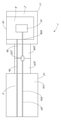
도 1a는 근관 치아로부터 건강에 해롭거나 바람직하지 않은 물질을 제거하는 것이 가능한 구성요소를 포함하는 시스템의 개략도이다.
도 1b는 치아의 외부면 상의 치료 영역으로부터 건강에 해롭거나 바람직하지 않은 물질을 제거하는 것이 가능한 구성요소를 포함하는 시스템의 개략도이다.
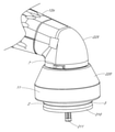
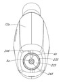
도 2a는 일 실시예에 따른 치료 기구의 개략 사시도이다.
도 2b는 도 2a의 치료 기구의 핸드피스의 원위 단부 부분에 배치된 유체 플랫폼의 확대 개략 사시도이다.
도 2c는 도 2a의 치료 기구의 개략 저면 사시도이다.
도 2d는 도 2a의 섹션 2D-2D를 따라 취한, 도 2a의 치료 기구의 개략 측단면도이다.
도 2e는 유체 플랫폼의 확대 저면 사시 단면도이다.
도 2f는 도 2d의 섹션에 도시되어 있는 유체 플랫폼의 확대도이다.
도 2g는 도 2a의 섹션 2G-2G를 따라 취한 유체 플랫폼의 개략 측단면도이다.
도 2h는 도 2f의 섹션 2H-2H를 따라 취한 유체 플랫폼의 평면 사시 단면도이다.
도 2i는 도 2f의 섹션 2I-2I를 따라 취한 유체 플랫폼의 평면 사시 단면도이다.
도 2j는 섹션 2J-2J를 따라 취한 유체 플랫폼의 평면도이다.
도 2k는 섹션 2I-2I를 따라 취한 유체 플랫폼의 평면도이다.
도 3a는 다른 실시예에 따른, 콘트라앵글(contra-angled) 핸드피스 본체를 갖는 치료 기구의 개략 사시도이다.
도 3b는 도 3a의 치료 기구의 개략 측면도이다.
도 3c는 도 3a 및 도 3b의 치료 기구의 개략 사시 단면도이다.
도 4a는 다양한 실시예에 따른, 치료 기구의 개략 저면 우측 사시도이다.
도 4b는 도 4a의 치료 기구의 개략 평면 좌측 사시도이다.
도 4c는 도 4a 및 도 4b의 치료 기구의 개략 측면 사시 단면도이다.
도 5는 다양한 실시예에 따른 치과 치료 기구의 개략도이다.
도 6은 다양한 실시예에 따른 치과 치료 기구의 개략도이다.
도 7은 다양한 실시예에 따른 치과 치료 기구의 개략도이다.
도 8은 다양한 실시예에 따른 치과 치료 기구의 개략 정면 사시도이다.
도 9는 도 8의 치료 기구의 커넥터의 개략 확대 사시도이다.
도 10은 도 8의 치료 기구의 커넥터의 개략 사시 단면도이다.
도 11은 도 8의 치료 기구의 팁 디바이스의 개략 사시 단면도이다.
도 12는 다양한 실시예에서 제공될 수 있는 하나 이상의 통기구를 도시하고 있는 도 8의 기구의 커넥터의 개략 부분 단면도이다.
도 13a는 도 8의 치료 기구의 팁 디바이스의 개략 정면 평면 사시도이다.
도 13b는 도 13a의 팁 디바이스의 개략 후면 저면 사시도이다.
도 13c는 도 13a의 팁 디바이스의 개략 평면도이다.
도 13d는 도 13a의 팁 디바이스의 개략 저면도이다.
도 13e는 도 13a의 팁 디바이스의 개략 정면도이다.
도 13f는 도 13a의 팁 디바이스의 개략 좌측 측면도이다.
도 13g는 부가의 커버 부재가 팁 디바이스의 외부면에 제공되는 도 8의 팁 디바이스의 개략 사시도이다.
도 13h는 도 8의 치과 치료 기구의 커넥터 및 가이드 튜브의 개략 측면도이다.
도 14a는 도 8의 치과 치료 기구의 개략 후면 사시도이다.
도 14b는 도 8의 치과 치료 기구의 개략 정면도이다.
도 14c는 도 8의 치과 치료 기구의 개략 후면도이다.
도 14d는 도 8의 치과 치료 기구의 개략 평면도이다.
도 14e는 도 8의 치과 치료 기구의 개략 저면도이다.
도 14f는 도 8의 치과 치료 기구의 개략 좌측 측면도이다.
도 14g는 도 8의 치과 치료 기구의 개략 우측 측면도이다.
도 15는 다양한 실시예에 따른 치과 치료 기구의 개략 단면도이다.
도 16a는 도 15의 치과 치료 기구의 핸드피스 본체의 개략 정면 사시도이다.
도 16b는 도 16a의 핸드피스 본체의 후면 사시도이다.
도 16c는 도 16a의 핸드피스 본체의 정면도이다.
도 16d는 도 16a의 핸드피스 본체의 후면도이다.
도 16e는 도 16a의 핸드피스 본체의 개략 사시 단면도이다.
도 16f는 도 16a의 핸드피스 본체의 측단면도이다.
도 16g는 도 16a의 핸드피스 본체의 원위 부분의 개략 평면 우측 사시도이다.
도 16h는 도 16a의 핸드피스 본체의 원위 부분의 개략적인 평면 사시도이다.
도 16i는 도 16a의 핸드피스 본체의 원위 부분의 개략 평면 좌측 사시도이다.
도 17a는 도 15의 치과 치료 기구의 팁 디바이스의 측단면도이다.
도 17b는 도 17a의 팁 디바이스의 단면 평면도이다.
도 18a는 다양한 실시예에 따른 팁 디바이스의 개략 측단면도이다.
도 18b는 도 18a의 팁 디바이스의 개략 평면 단면도이다.
도 19는 다양한 실시예에 따른 팁 디바이스의 개략 측단면도이다.
도 20은 다양한 실시예에 따른 팁 디바이스의 개략 후면 사시도이다.
도 21은 다양한 실시예에 따른 팁 디바이스의 개략 후면 사시도이다.
도 22는 다양한 실시예에 따른 팁 디바이스의 개략 정면 사시도이다.
도 23은 다양한 실시예에 따른 팁 디바이스의 개략 정면 사시도이다.
도 24는 팁 디바이스의 커넥터의 실시예를 도시하고 있는 개략 후면 사시도이다.
도 25는 다양한 실시예에 따른 팁 디바이스의 사시도이다.
도 26은 로킹 메커니즘의 실시예의 개략 부분도이다.
도 27은 팁 디바이스용 커버의 다양한 실시예의 사시도이다.
도 28a는 다양한 실시예에 따른 핸드피스 본체의 개략 정면 사시도이다.
도 28b는 도 28a의 핸드피스 본체의 개략 단면 사시도이다.
도 29는 핸드피스 본체의 커넥터의 실시예의 개략 부분도이다.
도 30은 로킹 메커니즘의 실시예의 핸드피스 본체 부분의 개략 부분도이다.
도면 전체에 걸쳐, 달리 언급되지 않으면, 참조 번호는 참조된 요소들 사이의 일반적인 대응을 나타내기 위해 재사용될 수도 있다. 도면은 본 명세서에 설명된 예시적인 실시예를 예시하기 위해 제공되고 본 개시내용의 범주를 한정하도록 의도되지 않는다.The above and other features, aspects and advantages of embodiments of devices and methods for treating (eg, cleaning teeth) teeth are described below with reference to the drawings of various embodiments, which are intended to illustrate and not to limit embodiments of the present invention. is described in detail in The drawings include the following drawings, wherein:
1A is a schematic diagram of a system comprising components capable of removing unhealthy or undesirable material from a root canal tooth;
1B is a schematic diagram of a system comprising components capable of removing unhealthy or undesirable substances from a treatment area on the outer surface of a tooth;
2A is a schematic perspective view of a treatment instrument according to one embodiment.
FIG. 2B is an enlarged schematic perspective view of a fluid platform disposed at a distal end portion of the handpiece of the treatment instrument of FIG. 2A ;
FIG. 2C is a schematic bottom perspective view of the treatment instrument of FIG. 2A ;
FIG. 2D is a schematic side cross-sectional view of the treatment instrument of FIG. 2A , taken along section 2D-2D of FIG. 2A .
2E is an enlarged bottom perspective cross-sectional view of the fluid platform.
FIG. 2F is an enlarged view of the fluid platform shown in the section of FIG. 2D .
FIG. 2G is a schematic side cross-sectional view of the fluid platform taken along sections 2G-2G of FIG. 2A ;
FIG. 2H is a top perspective cross-sectional view of the fluid platform taken along
FIG. 2I is a top perspective cross-sectional view of the fluid platform taken along sections 2I-2I of FIG. 2F ;
2J is a top view of the fluid platform taken along
2K is a top view of the fluid platform taken along sections 2I-2I.
3A is a schematic perspective view of a treatment instrument having a contra-angled handpiece body, according to another embodiment.
3B is a schematic side view of the treatment instrument of FIG. 3A ;
3C is a schematic isometric cross-sectional view of the treatment instrument of FIGS. 3A and 3B ;
4A is a schematic bottom right perspective view of a treatment instrument, in accordance with various embodiments.
4B is a schematic top left perspective view of the treatment instrument of FIG. 4A ;
4C is a schematic side perspective cross-sectional view of the treatment instrument of FIGS. 4A and 4B ;
5 is a schematic diagram of a dental treatment instrument in accordance with various embodiments.
6 is a schematic diagram of a dental treatment instrument in accordance with various embodiments.
7 is a schematic diagram of a dental treatment instrument in accordance with various embodiments.
8 is a schematic front perspective view of a dental treatment instrument in accordance with various embodiments.
9 is a schematic enlarged perspective view of a connector of the treatment instrument of FIG. 8 ;
10 is a schematic isometric cross-sectional view of a connector of the treatment instrument of FIG. 8 ;
11 is a schematic isometric cross-sectional view of the tip device of the treatment instrument of FIG. 8 ;
12 is a schematic partial cross-sectional view of the connector of the appliance of FIG. 8 illustrating one or more vents that may be provided in various embodiments.
13A is a schematic front plan perspective view of the tip device of the treatment instrument of FIG. 8 ;
13B is a schematic rear bottom perspective view of the tip device of FIG. 13A ;
13C is a schematic top view of the tip device of FIG. 13A ;
13D is a schematic bottom view of the tip device of FIG. 13A ;
13E is a schematic front view of the tip device of FIG. 13A ;
13F is a schematic left side view of the tip device of FIG. 13A ;
13G is a schematic perspective view of the tip device of FIG. 8 with an additional cover member provided on the outer surface of the tip device;
13H is a schematic side view of a connector and guide tube of the dental treatment instrument of FIG. 8 ;
14A is a schematic rear perspective view of the dental treatment instrument of FIG. 8 ;
14B is a schematic front view of the dental treatment instrument of FIG. 8 ;
14C is a schematic rear view of the dental treatment instrument of FIG. 8 ;
14D is a schematic plan view of the dental treatment instrument of FIG. 8 ;
14E is a schematic bottom view of the dental treatment instrument of FIG. 8 ;
14F is a schematic left side view of the dental treatment instrument of FIG. 8 ;
14G is a schematic right side view of the dental treatment instrument of FIG. 8 ;
15 is a schematic cross-sectional view of a dental treatment instrument in accordance with various embodiments.
16A is a schematic front perspective view of the handpiece body of the dental treatment instrument of FIG. 15 ;
Figure 16b is a rear perspective view of the handpiece body of Figure 16a.
Figure 16c is a front view of the handpiece body of Figure 16a.
Figure 16d is a rear view of the handpiece body of Figure 16a.
16E is a schematic perspective cross-sectional view of the handpiece body of FIG. 16A ;
Figure 16f is a side cross-sectional view of the handpiece body of Figure 16a.
16G is a schematic top right perspective view of a distal portion of the handpiece body of FIG. 16A ;
16H is a schematic top perspective view of a distal portion of the handpiece body of FIG. 16A ;
16I is a schematic top left perspective view of the distal portion of the handpiece body of FIG. 16A ;
17A is a cross-sectional side view of the tip device of the dental treatment instrument of FIG. 15 ;
17B is a cross-sectional plan view of the tip device of FIG. 17A .
18A is a schematic cross-sectional side view of a tip device in accordance with various embodiments.
18B is a schematic top cross-sectional view of the tip device of FIG. 18A ;
19 is a schematic cross-sectional side view of a tip device in accordance with various embodiments.
20 is a schematic rear perspective view of a tip device in accordance with various embodiments.
21 is a schematic rear perspective view of a tip device in accordance with various embodiments.
22 is a schematic front perspective view of a tip device in accordance with various embodiments.
23 is a schematic front perspective view of a tip device in accordance with various embodiments.
24 is a schematic rear perspective view showing an embodiment of a connector of a tip device;
25 is a perspective view of a tip device in accordance with various embodiments.
26 is a schematic partial view of an embodiment of a locking mechanism;
27 is a perspective view of various embodiments of a cover for a tip device.
28A is a schematic front perspective view of a handpiece body in accordance with various embodiments;
Fig. 28B is a schematic cross-sectional perspective view of the handpiece body of Fig. 28A;
29 is a schematic partial view of an embodiment of a connector of the handpiece body;
30 is a schematic partial view of a handpiece body portion of an embodiment of a locking mechanism;
Throughout the drawings, unless stated otherwise, reference numbers may be reused to indicate general correspondences between referenced elements. The drawings are provided to illustrate the exemplary embodiments described herein and are not intended to limit the scope of the disclosure.
본 개시내용은 치과 및/또는 근관 치료 절차를 수행하기 위한 장치, 방법, 및 조성물을 설명한다. 본 명세서에 개시된 다양한 실시예는 치아의 치료 영역으로부터, 예를 들어 치아 내로부터 그리고/또는 치아의 표면 외부로부터 건강에 해로운 물질을 효과적으로 안전하게 제거할 수 있다. 특히, 본 명세서에 개시된 실시예는 건강에 해로운 유기물, 무기물, 치수(pulp) 조직, 우식, 얼룩, 치석, 플라크, 미생물막, 박테리아, 고름, 썩은 치아 물질 및 음식물 찌꺼기와 같은 건강에 해로운 물질을 건강한 상아질 또는 법랑질을 실질적으로 손상시키지 않고 치료 영역으로부터 제거할 수 있다. 예를 들어, 개시된 장치, 방법 및 조성물은, 예를 들어, 근관계로부터 유기물 및/또는 무기물과 같은 건강에 해롭거나 바람직하지 않은 물질을 효율적으로 제거하기 위해 그리고/또는 근관계를 소독하기 위해 근관 세정 치료와 함께 유리하게 사용될 수도 있다. 개시된 실시예는 또한 치아의 외부면 상의 우식 영역을 치료하는 데(예를 들어, 썩은 물질을 제거함) 사용될 수도 있다. 유기 물질(또는 유기물)은 예를 들어 살아 있는, 염증이 있는, 감염된, 질환이 있는, 괴사성, 또는 분해된 연조직, 치수, 혈관, 신경, 결합 조직, 세포 물질, 고름 및 미생물과 같은 건강한 또는 질환이 있는 치아 또는 근관계에서 전형적으로 발견되는 유기 물질을 포함한다. 무기물은 근관계 내에 빈번히 존재하는 석회화된 조직 및 석회화된 구조를 포함한다. 몇몇 실시예에서, 근관은 근관의 치료 후에 충전 물질(예를 들어, 고체 또는 반고체 상태로 경화될 수 있는 유동성 충전 물질, 구타페르카 또는 다른 고체 또는 반고체 물질)로 충전될 수 있다.This disclosure describes devices, methods, and compositions for performing dental and/or root canal treatment procedures. Various embodiments disclosed herein can effectively and safely remove unhealthy substances from a treatment area of a tooth, for example from within and/or from outside the surface of a tooth. In particular, the embodiments disclosed herein are effective against unhealthy substances such as unhealthy organic matter, inorganic matter, pulp tissue, caries, stains, tartar, plaque, microbiota, bacteria, pus, decaying tooth material and food debris. Healthy dentin or enamel can be removed from the treatment area without substantially damaging it. For example, the disclosed devices, methods and compositions can be used, for example, to efficiently remove unhealthy or undesirable substances, such as organic and/or inorganic matter, from the root canal and/or to disinfect the root canal. It may also be advantageously used in conjunction with a cleansing treatment. The disclosed embodiments may also be used to treat (eg, remove decayed material) a carious area on the exterior surface of a tooth. Organic matter (or organic matter) can be a healthy or Includes organic materials typically found in diseased teeth or root systems. Minerals include calcified tissue and calcified structures frequently present in the root system. In some embodiments, the root canal may be filled with a filling material (eg, a flowable filling material that can be set to a solid or semi-solid state, gutta percha or other solid or semi-solid material) after treatment of the root canal.
I. 다양한 개시된 실시예의 개요I. Summary of Various Disclosed Embodiments
도 1a는 치아(110)로부터 건강에 해롭거나 바람직하지 않은 물질을 제거하는 것이 가능한 구성요소를 포함하는 시스템(100)의 개략도이다. 도 1a에 도시되어 있는 치아(110)는 소구치, 예를 들어 인간과 같은 포유동물의 견치와 대구치 사이에 위치된 치아이다. 도시되어 있는 치아(110)는 소구치를 포함하지만, 치료될 치아(110)는 대구치 또는 전치(예를 들어, 절치 또는 견치)와 같은 임의의 유형의 치아일 수 있다는 것이 이해되어야 한다. 치아(110)는 상아질(116)의 경질층과 법랑질(117)의 매우 경질 외부층을 포함하는, 경질 구조층 및 보호층을 포함한다. 치수강(111)이 상아질(116) 내에 형성된다. 치수강(111)은 각각의 치근(112)의 첨단(114)을 향해 연장하는 하나 이상의 근관(113)을 포함한다. 치수강(111) 및 근관(113)은 신경, 혈관, 결합 조직, 상아모세포, 및 다른 조직 및 세포 성분을 포함하는 연성 혈관 조직인 치수를 포함한다. 혈관 및 신경은 치근(112)의 첨단(114)의 팁 부근에 있는 작은 개구, 치근단 구멍 또는 치근단 개구(115)를 통해 근관(113)에 진입/진출한다. 본 명세서에 예시된 치아(110)는 소구치이지만, 본 명세서에 개시된 실시예는 구치, 견치, 절치 등을 포함하는 임의의 적합한 유형의 치아를 치료하는 데 유리하게 사용될 수 있다는 것이 이해되어야 한다.1A is a schematic diagram of a
도 1a에 도시되어 있는 바와 같이, 시스템(100)은 치아(110)의 내부로부터, 예를 들어 치아(110)의 근관(113)으로부터 건강에 해로운 물질(유기물 및 무기물과 같은)을 제거하는 데 사용될 수 있다. 예를 들어, 근관 치료 접근 개구(118)가 치아(110) 내에, 예를 들어 교합면 상에 또는 협면 또는 설면과 같은 측면 상에 형성될 수 있다. 접근 개구(118)는 치아(110)의 치수강(111)의 부분에 대한 접근을 제공한다. 시스템(100)은 콘솔(102)과, 압력파 발생기(10) 및 치아(110)의 치료 영역 위에 또는 기대어 위치되도록 구성된 유체 플랫폼(2)을 포함하는 치료 기구(1)를 포함할 수 있다. 유체 플랫폼(2)은 그 내에 유체를 보유하도록 구성된 챔버(6)를 형성할 수 있다. 몇몇 실시예에서, 유체 플랫폼(2)은 임상의에 의해 치아(110)에 대해 유지되거나 가압될 수 있는 핸드피스에 제거 가능하게 결합된 제거 가능한 팁 디바이스의 부분일 수 있다. 다른 실시예에서, 유체 플랫폼(2)은 핸드피스에 제거 가능하게 연결되지 않을 수도 있는데, 예를 들어, 유체 플랫폼(2)은 핸드피스와 일체로 형성될 수도 있거나, 제거 불가능하도록 의도된 방식으로 핸드피스에 연결될 수도 있다. 몇몇 실시예에서, 유체 플랫폼(2)은 예를 들어 접착제를 사용하여 치아에 부착될 수 있다. 예를 들어, 몇몇 실시예에서, 유체 플랫폼(2)은 핸드피스와 함께 사용되지 않을 수도 있다. 하나 이상의 도관(104)은 콘솔(102)을 유체 플랫폼(2) 및 압력파 발생기(10)와 전기적으로, 기계적으로 및/또는 유동적으로 연결할 수 있다. 콘솔(102)은 치료 절차 중에 압력파 발생기(10)를 동작시키도록 구성된 제어 시스템 및 다양한 유체 관리 시스템을 포함할 수 있다. 시스템(100)에서 사용될 수 있는 시스템 구성요소의 부가의 예는 그 전체 내용이 모든 목적을 위해 그대로 본 명세서에 참조로서 합체되어 있는 미국 특허 제9,504,536호 전체에 걸쳐 개시되어 있다.As shown in FIG. 1A , the
본 명세서에 설명된 바와 같이, 시스템(100)은 실질적으로 전체 근관계를 세정하기 위한 세정 절차에 사용될 수 있다. 예를 들어, 본 명세서에 개시된 다양한 실시예에서, 압력파 발생기(10)는 단일 주파수 또는 다중 주파수를 갖는 압력파를 발생할 수 있다. 단일 주파수는 가청 범위 미만의 낮은 주파수, 가청 범위 내의 주파수, 또는 가청 범위 초과의 비교적 더 높은 주파수일 수도 있다. 예를 들어, 본 명세서에 개시된 다양한 실시예에서, 압력파 발생기(10)는 챔버(6) 내에 유체 운동(24)을 생성하기에 충분한 전력 및 비교적 낮은 주파수의 압력파(23)를 발생할 수 있고 - 본 명세서에 개시된 압력파 발생기(10)가 유체 운동 발생기로서 작용할 수 있도록 - 치아 내부 또는 외부의 치아 표면에 표면 효과 캐비테이션을 생성하기에 충분한 전력 및 비교적 더 높은 주파수의 압력파를 발생할 수 있다. 즉, 예를 들어, 본 명세서에 개시된 압력파 발생기(10)는 치아(110) 내 또는 부근에서 대규모 또는 벌크 유체 운동(24)을 발생시키는 유체 운동 발생기로서 작용할 수 있고, 또한 더 높은 주파수에서 더 소규모 유체 운동을 발생할 수 있다. 몇몇 배열에서, 챔버(6) 내의 유체 운동(24)은 관(113)을 세정 및/또는 충전할 수 있는 와류(75), 소용돌이, 혼돈 또는 난류 유동 등과 같은 유도된 유체 운동을 치아(110) 및 근관(113) 내에 발생할 수 있다.As described herein,
몇몇 실시예에서, 시스템(100)은 부가적으로 또는 대안적으로 치아의 치료된 영역을 충전하기 위해, 예를 들어 치료된 근관계를 충전하기 위해 충전 절차에서 사용될 수 있다. 치료 기구(1)는 유동성 충전 물질이 치료 영역을 실질적으로 충전하게 할 수 있는 압력파 및 유체 운동을 생성할 수 있다. 유동성 충전 물질은 치아를 복원하기 위해 경화될 수 있다. 치료 영역을 충전하기 위해 압력파 발생기(10)를 이용하는 시스템의 부가의 상세는 그 전체 내용이 모든 목적을 위해 그대로 본 명세서에 참조로서 합체되어 있는 미국 특허 제9,877,801호 전체에 걸쳐 발견될 수 있다.In some embodiments,
도 1b는 치아의 외부면(119) 상의 치료 영역으로부터 건강에 해롭거나 바람직하지 않은 물질을 제거하는 것이 가능한 구성요소를 포함하는 시스템(100)의 개략도이다. 예를 들어, 도 1a에서와 같이, 시스템(100)은 유체 플랫폼(2) 및 압력파 발생기(10)를 포함하는 치료 기구(1)를 포함할 수 있다. 유체 플랫폼(2)은 하나 이상의 도관(104)을 통해 콘솔(102)과 연통할 수 있다. 그러나, 도 1a의 시스템(100)과는 달리, 유체 플랫폼(2)은 치아(10)의 외부면(119) 상의 치료 영역에 결합된다. 예를 들어, 도 1b의 시스템(1)은 치아(110)의 외부면, 예를 들어 치아(110)의 우식 영역을 세정하도록 활성화될 수 있다. 이러한 실시예에서, 임상의는 압력파 발생기(10)와 치료 영역 사이의 유체 연통을 제공하기 위해 질환이 있는 조직을 포함하는 치아(110)의 임의의 표면 또는 영역 위에 챔버(6)를 제공할 수 있다. 도 1a의 실시예에서와 같이, 유체 운동(24)은 유체 플랫폼(2) 및 챔버(6) 내에 발생될 수 있는데, 이는 치아(110)의 치료 영역을 세정하도록 작용할 수 있다. 또한, 전술된 바와 같이, 시스템(100)은 부가적으로 또는 대안적으로 치료 영역, 예를 들어 치아(110)의 외부면(119) 상의 치료된 우식 영역을 충전하기 위해 사용될 수 있다.1B is a schematic diagram of a
본 명세서에 설명된 바와 같이, 개시된 압력파 발생기(10)는 치아로부터 바람직하지 않은 물질을 세정하기에 충분한 에너지를 갖는 압력파(23)를 발생하도록 구성될 수 있다. 압력파 발생기(10)는 일 형태의 에너지를 치료 액체 내에서 압력파(23)로 변환하는 디바이스일 수 있다. 압력파 발생기(10)는 다른 현상 중에서, 치료 액체의 유체 역학 운동(예를 들어, 챔버(6) 내의), 유체 순환, 난류, 및 치아(110)의 세정을 가능하게 할 수 있는 다른 조건을 유도할 수 있다. 본 명세서에 설명된 각각의 도면에 개시된 압력파 발생기(10)는 임의의 적합한 유형의 압력파 발생기일 수도 있다.As described herein, the disclosed
압력파 발생기(10)는 치료 액체를 통해, 예를 들어 유체 플랫폼(2) 내에 적어도 부분적으로 보유된 치료 유체를 통해 전파하는 압력파(23)를 생성함으로써 치아(110)를 세정하는 데 사용될 수 있다. 몇몇 구현예에서, 압력파 발생기(10)는 또한 캐비테이션, 음향 스트리밍, 충격파, 난류 등을 생성할 수도 있다. 다양한 실시예에서, 압력파 발생기(10)는 광대역 전력 스펙트럼을 갖는 압력파(23) 또는 음향 에너지를 발생할 수 있다. 예를 들어, 압력파 발생기(10)는 단지 하나 또는 소수의 주파수에 대조적으로, 다중의 상이한 주파수에서 음향파를 발생할 수 있다. 이론에 의해 제한되지 않고, 다중 주파수에서의 전력의 발생은 다양한 주파수에서 상이한 물질 또는 물리적 특성을 갖는 다양한 유형의 유기 및/또는 무기 물질을 제거하는 것을 도울 수 있는 것으로 고려된다.The
몇몇 실시예에서, 압력파 발생기(10)는 액체 제트 디바이스를 포함할 수 있다. 액체 제트는 오리피스를 통해 고압 액체를 통과시킴으로써 생성될 수 있다. 액체 제트는 치료 액체 내에 압력파(23)를 생성할 수 있다. 몇몇 실시예에서, 압력파 발생기(10)는 간섭성, 시준된 액체 제트를 포함한다. 액체의 제트는 실질적으로 봉입된 체적(예를 들어, 챔버(6)) 및/또는 충돌 부재(예를 들어, 가이드 튜브의 원위 단부 상의 원위 충돌 플레이트 또는 챔버 벽의 만곡 표면) 내의 액체와 상호 작용하여 압력파(23)를 생성할 수 있다. 게다가, 제트와 치료 유체의 상호 작용, 뿐만 아니라 충돌 부재와 치료 유체의 타격으로부터 발생하는 스프레이의 상호 작용은 치아를 세정하기 위한 캐비테이션 및/또는 다른 음향 효과를 생성하는 것을 보조할 수도 있다. 다른 실시예에서, 압력파 발생기(10)는 본 명세서에 설명된 바와 같이, 레이저 디바이스를 포함할 수 있다. 기계 디바이스와 같은 다른 유형의 압력파 발생기가 또한 적합할 수도 있다.In some embodiments, the
본 명세서에 개시된 압력파 발생기(10)는 다중 주파수를 갖는 광대역 음향 스펙트럼을 갖는 압력파를 발생할 수 있다. 압력파 발생기(10)는, 예를 들어, 약 1 kHz 내지 약 1000 kHz의 범위의 유효 전력을 포함하여, 약 1 Hz로부터 약 1000 kHz까지 확장되는 유효 전력을 갖는 음향 전력의 광대역 전력 스펙트럼을 발생할 수 있다(예를 들어, 대역폭은 약 1000 kHz일 수 있음). 음향 에너지 스펙트럼의 대역폭은, 몇몇 경우에 3-데시벨(3-dB) 대역폭(예를 들어, 음향 전력 스펙트럼의 반치전폭 또는 FWHM)의 견지에서 측정될 수도 있다. 다양한 예에서, 광대역 음향 전력 스펙트럼은 약 1 Hz 내지 약 500 kHz의 범위, 약 1 kHz 내지 약 500 kHz의 범위, 약 10 kHz 내지 약 100 kHz의 범위, 또는 몇몇 다른 주파수의 범위의 대역폭의 유효 전력을 포함할 수 있다. 몇몇 구현예에서, 광대역 스펙트럼은 약 1 MHz 초과의 음향 전력을 포함할 수 있다. 유리하게는, 음향 전력의 광대역 스펙트럼은 캐비테이션 구름 내에 그리고 치아 표면 상에 비교적 넓은 범위의 기포 크기를 생성할 수 있고, 이들 기포의 내파(implosion)는 좁은 크기 범위를 갖는 기포보다 조직 파괴에 더 효과적일 수도 있다. 비교적 광대역 음향 전력은 또한 음향 에너지가, 예를 들어 세포 규모로부터 최대 조직 규모까지의 길이 규모의 범위에서 작용하게 할 수도 있다. 이에 따라, 광대역 음향 전력 스펙트럼을 생성하는 압력파 발생기(예를 들어, 액체 제트의 몇몇 실시예)는 협대역 음향 전력 스펙트럼을 생성하는 압력파 발생기보다 몇몇 치료를 위한 치아 세정에 더 효과적일 수 있다. 광대역 음향 전력을 생성하는 압력파 발생기의 부가의 예는 도 2a 및 도 2b 및 미국 특허 제9,675,426호의 연관 개시내용에, 그리고 도 13a 내지 도 14 및 미국 특허 제10,098,717호의 연관 개시내용에 설명되어 있고, 이들 미국 특허 각각의 전체 내용은 모든 목적을 위해 그대로 본 명세서에 참조로서 합체되어 있다.The
본 명세서에 개시된 치과 치료는 임의의 적합한 유형의 치료 유체, 예를 들어 세정 유체와 함께 사용될 수 있다. 충전 절차에서, 치료 유체는 치료 영역을 충전하기 위해 경화될 수 있는 유동성 충전 물질을 포함할 수 있다. 본 명세서에 개시된 치료 유체는 예를 들어 물, 식염수 등을 포함하는 임의의 적합한 유체일 수 있다. 몇몇 실시예에서, 치료 유체는 탈가스될 수 있는데, 이는 몇몇 치료에서 캐비테이션을 개선하고 그리고/또는 가스 기포의 존재를 감소시킬 수도 있다. 몇몇 실시예에서, 용해된 가스 함량은 약 1 체적 % 미만일 수 있다. 예를 들어, 조직 용해제(예를 들어, NaOCl), 소독제(예를 들어, 클로르헥시딘), 마취제, 플루오린화물 요법제, EDTA, 시트르산, 및 임의의 다른 적합한 화학물을 포함하는 다양한 화학물이 치료 용액에 첨가될 수 있다. 예를 들어, 임의의 다른 항균, 탈회, 소독, 광화(mineralizing) 또는 미백 용액이 마찬가지로 사용될 수도 있다. 다양한 용액이 적합한 농도로 동시에 또는 순차적으로 조합하여 사용될 수도 있다. 몇몇 실시예에서, 화학물 및 화학물의 농도는 환자 결과를 개선하기 위해 임상의에 의해 및/또는 시스템에 의해 절차 전체에 걸쳐 변경될 수 있다. 압력파 발생기(10)에 의해 발생된 압력파(23) 및 유체 운동(24)은 치료 영역 전체에 걸쳐 바람직하지 않은 물질을 제거할 수 있는 저주파 벌크 유체 운동 및/또는 고주파 음향파를 유도함으로써 세정의 효능을 유리하게 개선할 수 있다.The dental treatments disclosed herein can be used with any suitable type of treatment fluid, such as a cleaning fluid. In a filling procedure, the treatment fluid may include a flowable filling material that can be cured to fill the treatment area. The therapeutic fluid disclosed herein can be any suitable fluid including, for example, water, saline, and the like. In some embodiments, the treatment fluid may be degassed, which may improve cavitation and/or reduce the presence of gas bubbles in some treatments. In some embodiments, the dissolved gas content may be less than about 1 volume %. Various chemistries include, for example, tissue lysing agents (eg, NaOCl), antiseptics (eg, chlorhexidine), anesthetics, fluoride therapies, EDTA, citric acid, and any other suitable chemical. may be added to the solution. For example, any other antibacterial, demineralizing, disinfecting, mineralizing or whitening solution may likewise be used. Various solutions may be used in combination at suitable concentrations either simultaneously or sequentially. In some embodiments, chemicals and concentrations of chemicals may be altered throughout the procedure by the clinician and/or by the system to improve patient outcomes. The pressure waves 23 and
몇몇 시스템 및 방법에서, 시스템(100)과 함께 사용되는 치료 유체는 유체의 정상 가스 함량과 비교할 때 감소되는 용해된 가스 함량을 갖는 탈가스된 유체를 포함할 수 있다. 탈가스된 치료 유체의 사용은, 유체 내의 기포의 존재가 음향 에너지의 전파를 방해하고 세정의 유효성을 감소시킬 수도 있기 때문에, 세정 효능을 유리하게 개선시킬 수 있다. 몇몇 실시예에서, 탈가스된 유체는 유체의 소스로부터 전달될 때(예를 들어, 탈가스 전에) 그 정상량의 대략 10% 내지 40%로 감소되는 용해된 가스 함량을 갖는다. 다른 실시예에서, 탈가스된 유체의 용해된 가스 함량은 유체의 정상 가스 함량의 대략 5% 내지 50% 또는 1% 내지 70%로 감소될 수 있다. 몇몇 치료에서, 용해된 가스 함량은 정상 가스량의 약 70% 미만, 약 50% 미만, 약 40% 미만, 약 30% 미만, 약 20% 미만, 약 10% 미만, 약 5% 미만, 또는 약 1% 미만일 수 있다. 몇몇 실시예에서, 탈가스된 유체는 오존과 같은 특정 유형의 가스에 노출될 수도 있고, 예를 들어 가스 기포의 형태로, 가스(예를 들어, 오존)의 일부를 그와 함께 치료 영역 내로 운반할 수도 있다. 치료 영역에서, 가스 기포는 영역의 추가 소독을 위해 치료 영역을 가스(예를 들어, 오존)에 노출시킨다. 탈가스된 치료 액체의 사용에 관한 부가의 상세는 모든 목적을 위해 그대로 참조로서 본 명세서에 합체되어 있는 미국 특허 제9,675,426호에서 발견될 수도 있다.In some systems and methods, a treatment fluid used with
II. 치료 기구의 예II. Example of a treatment device
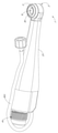
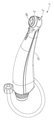
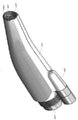
본 명세서에 개시된 다양한 실시예는 치아(110)의 치료 영역을 세정 및/또는 충전하도록 구성된 치과 치료 기구(1)에 관한 것이다. 본 명세서에 개시된 치료 기구는 치아(110)의 외부면 상의 근관 공간 및 연관 세관 및 우식 영역을 포함하여, 치아(110) 세정시 개선된 효능을 입증한다.Various embodiments disclosed herein relate to a
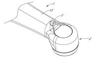
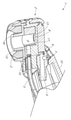
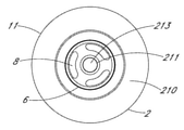
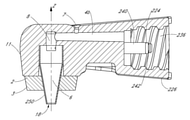
도 2a 내지 도 2k는 이러한 치료 기구(1)의 예를 도시하고 있다. 특히, 도 2a는 일 실시예에 따른 치료 기구(1)의 개략 사시도이다. 도 2b는 도 2a의 치료 기구(1)의 핸드피스(12)의 원위 단부 부분에 배치된 유체 플랫폼(2)의 확대 개략 사시도이다. 도 2c는 도 2a의 치료 기구(1)의 개략 저면 사시도이다. 도 2d는 도 2a의 섹션 2D-2D를 따라 취한, 도 2a의 치료 기구(1)의 개략 측단면도이다. 도 2e는 유체 플랫폼(2)의 확대 저면 사시 단면도이다. 도 2f는 도 2d의 섹션에 도시되어 있는 유체 플랫폼(2)의 확대도이다. 도 2g는 도 2a의 섹션 2G-2G를 따라 취한 유체 플랫폼(2)의 개략 측단면도이다. 도 2h는 도 2f의 섹션 2H-2H를 따라 취한 유체 플랫폼(2)의 평면 사시 단면도이다. 도 2i는 도 2f의 섹션 2I-2I를 따라 취한 유체 플랫폼(2)의 평면 사시 단면도이다. 도 2j는 섹션 2J-2J를 따라 취한 유체 플랫폼(2)의 평면도이다. 도 2k는 섹션 2I-2I를 따라 취한 유체 플랫폼(2)의 평면도이다.2a to 2k show examples of such a
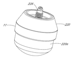
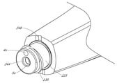
도 2a 내지 도 2k의 치료 기구(1)는 임상의에 의해 파지되도록 크기 설정되고 성형된 핸드피스(12)를 포함한다. 유체 플랫폼(2)은 핸드피스(12)의 원위 부분에 결합될 수 있다. 본 명세서에 설명된 바와 같이, 몇몇 실시예에서, 유체 플랫폼(2)은 핸드피스(12)에 제거 가능하게 연결될 수 있는 제거 가능한 팁 디바이스(11)(이하 참조)의 부분을 형성할 수 있다. 다른 실시예에서, 유체 플랫폼(2)은 핸드피스(12)에 제거 불가능하게 부착될 수 있거나 핸드피스(12)와 일체로 형성될 수 있다. 또 다른 실시예에서, 유체 플랫폼(12)은 핸드피스에 결합되지 않을 수도 있고, 대신에 핸드피스를 사용하지 않고 치아에 접착되는(또는 다른 방식으로 결합 또는 위치됨) 치료 캡으로서 역할을 할 수도 있다. 도 2a에 도시되어 있는 바와 같이, 인터페이스 부재(14)가 핸드피스(12)의 근위 단부 부분에 제공될 수 있는데, 이는 콘솔(102)과 치료 기구(1) 사이의 유체 연통을 제공하기 위해 하나 이상의 도관(104)에 제거 가능하게 결합될 수 있다.The
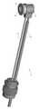
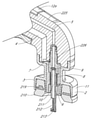
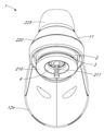
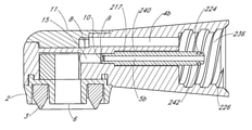
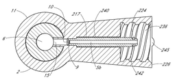
도 2a 및 도 2b에 도시되어 있는 바와 같이, 그리고 본 명세서에 설명된 바와 같이, 출구 라인(4)(전술된 적어도 하나의 도관(104) 중 하나를 포함할 수 있음)과 주위 공기 사이의 유체 연통을 제공하기 위해 통기구(7)가 핸드피스(12)의 부분을 통해 제공될 수 있다. 본 명세서에 설명된 바와 같이, 통기구(7)는 유체 플랫폼(2) 내의 압력을 조절하는 역할을 할 수 있고 치료 기구(1)의 안전 및 효능을 개선할 수 있다. 도 2c에 도시되어 있는 바와 같이, 접근 포트(18)가 유체 플랫폼(2)의 원위 부분에 제공되어 유체 플랫폼(2)에 의해 형성된 챔버(6)와 치아(110)의 치료 영역 사이에 유체 연통을 제공할 수 있다. 예를 들어, 도 1a에서 전술된 바와 같이, 근관 세정 절차에서, 유체 플랫폼(2)의 원위 부분에 있는 밀봉 캡(3)은 챔버(6)와 치아(110)의 내부(예를 들어, 치수강(111) 및 근관(들)(113)) 사이의 유체 연통을 제공하기 위해 접근 개구(118) 위에서 치아(110)에 대해 위치될 수 있다. 다른 실시예에서, 도 1b에서 전술된 바와 같이, 밀봉 캡(3)은 챔버(6)와 치료될 우식 영역 사이의 유체 연통을 제공하기 위해 치아(110)의 외부면(119)에서 우식 영역 위에서 치아(110)에 대해 위치될 수 있다. 압력파(23) 및 유체 운동(24)은 치료 영역을 세정하기 위해 치료 영역 전체에 걸쳐 전파될 수 있다.2A and 2B , and as described herein, fluid between the outlet line 4 (which may include one of the at least one
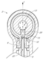
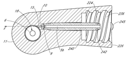
도 2d 내지 도 2g를 참조하면, 유체 플랫폼(2)은 챔버(6)를 형성하는 하나 또는 복수의 벽을 가질 수 있다. 예를 들어, 도 2e 내지 도 2g에 도시되어 있는 바와 같이, 유체 플랫폼(2)은 접근 포트(18)에 대향하는 챔버(6)의 상부 단부에 배치된 상부벽(17) 및 만곡된 측벽(13)을 포함하는 적어도 하나의 벽을 포함할 수 있다. 예시된 실시예에서, 만곡된 측벽(13)은 일반적으로 원형 단면을 갖는 일반적으로 원통형 챔버(6)를 형성할 수 있고, 상부벽(17)으로부터 소정 각도로 연장될 수 있다. 그러나, 다른 실시예에서, 만곡된 측벽(13)은 타원형일 수 있거나 다른 만곡된 또는 각을 이룬 표면을 가질 수 있다. 측벽(13)은 상부벽(17)에 비평행하게(예를 들어, 실질적으로 횡방향으로) 연장될 수 있다. 측벽(13)은 몇몇 실시예에서 예를 들어 약 90°만큼 임의의 적합한 0이 아닌 각도로 상부벽(17)으로부터 연장될 수 있다. 다른 실시예에서, 측벽(13)은 90° 초과 또는 미만의 각도만큼 상부벽(17)으로부터 연장될 수 있다. 다른 실시예에서, 측벽(13)은 챔버(6)의 형상이 불규칙하거나 비대칭일 수도 있도록 측벽(13)의 둘레를 따라 상이한 각도량만큼 상부벽(17)으로부터 연장될 수 있다. 예시된 실시예에서, 상부벽(17)과 측벽(13) 사이의 내부 각도는 각도 또는 코너를 포함할 수 있다. 그러나, 다른 실시예에서, 상부벽(17)과 측벽(13) 사이의 내부 인터페이스는 코너를 갖지 않는 만곡된 또는 평활한 표면을 포함할 수 있다. 예를 들어, 몇몇 실시예에서, 하나 이상의 벽은 준구형(quasi-spherical) 프로파일과 같은 만곡된 프로파일을 포함할 수 있다.2D-2G , the
밀봉 캡(3)은 플랫폼(2)과 결합되거나 함께 형성될 수 있다. 도시되어 있는 바와 같이, 예를 들어, 플랜지(16)는 대향 측면을 갖는 U형 지지부를 포함할 수 있고, 밀봉 캡(3)은 플랜지(16) 내에 배치될 수 있다. 플랜지(16)는 밀봉 캡(3)을 핸드피스(12)의 원위 부분에 기계적으로 연결하는 역할을 할 수 있다. 접근 포트(18)는 챔버(6)가 치아에 결합될 때(예를 들어, 치아에 대해 가압되고, 치아에 접착되거나, 다른 방식으로 치아에 결합됨) 치아(110)의 치료 영역과 유체 연통하여 챔버(6)를 배치하는 챔버(6)의 원위 단부 부분에 제공될 수 있다. 예를 들어, 밀봉 캡(3)은 치아의 치료 영역을 실질적으로 밀봉하기 위해 임상의에 의해 치아에 대해 가압될 수 있다.The sealing
챔버(6)는 임의의 적합한 프로파일을 갖도록 성형될 수 있다. 다양한 실시예에서, 그리고 도시되어 있는 바와 같이, 챔버(6)는 만곡된 측벽(13)을 가질 수 있지만, 다른 실시예에서, 챔버(6)는 각형성된 내부 코너를 형성할 수도 있는 복수의 각형성된 측벽(13)을 가질 수 있다. 챔버(6)의 단면 평면도(예를 들어, 저면 단면도)는 이에 따라 예를 들어 도 2c 및 도 2j에 도시되어 있는 바와 같이, 예를 들어 일반적으로 원형으로 라운딩될 수 있다. 몇몇 실시예에서, 챔버(6)의 단면 평면도(예를 들어, 저면 단면도)는 타원형, 다각형일 수 있거나, 불규칙한 경계를 가질 수 있다.
챔버(6)는 중심축(Z)을 가질 수 있다. 예를 들어, 도 2d에 도시되어 있는 바와 같이, 중심축(Z)은 접근 포트(18)의 중심(예를 들어, 기하학적 중심)을 통해(예를 들어, 접근 포트(18)에 의해 적어도 부분적으로 형성된 챔버(6)의 최원위 평면을 통해) 실질적으로 횡방향으로 연장될 수 있다. 다양한 실시예에서, 그리고 도 2d에 도시되어 있는 바와 같이, 원형(또는 대략 원형) 단면을 갖는(저면 평면도로부터 볼 때) 챔버(6)의 경우, 중심축(Z)은 챔버(6)의 원위 부분을 적어도 부분적으로 형성하는 접근 포트(18) 및/또는 챔버(6)의 상부를 적어도 부분적으로 형성하는 상부벽(17)의 대략 중심을 통해 실질적으로 횡방향으로 통과할 수 있다. 예를 들어, 중심축(Z)은 85° 내지 95°의 범위의 각도, 89° 내지 91°의 범위의 각도, 또는 89.5° 내지 90.5°의 범위의 각도로 상부벽(17) 및/또는 접근 포트(18)의 기하학적 중심을 통해 실질적으로 횡방향으로 통과할 수 있다.The
전술된 바와 같이, 예시된 챔버(6)는 일반적으로 또는 대략 원형 단면을 갖지만, 챔버(6)는 다양한 상향식(bottom-up) 단면에서 볼 때 다른 적합한 형상을 가질 수도 있다. 이러한 실시예에서, 챔버(6)의 접근 포트(18)의 개구 평면(챔버(6)의 최원위 평면에 있을 수도 있음)에 평행한 복수의 평면(예를 들어, 2개, 3개, 또는 그 초과의 평면)이 챔버의 측벽(13)에 의해 경계 한정되거나 경계 형성될 수 있다. 중심축(Z)은 접근 포트(18)에 평행한 경계 형성된 평면 각각의 대략적인 기하학적 중심을 통과할 수 있다. 예를 들어, 챔버(6)는 상부벽(17)에 대해 비횡방향으로 각형성된 측벽(13)을 가질 수도 있고 그리고/또는 챔버(6)의 높이(h)를 따라 변하는 프로파일을 갖는 측벽(13)을 가질 수도 있다. 중심축(Z)은 복수의 평행한 경계 형성 평면 각각의 기하학적 중심을 통과할 수 있다.As noted above, the illustrated
압력파 발생기(10)(유체 운동 발생기로서 역할을 할 수 있음)는 챔버(6) 내에 압력파 및 회전 유체 운동을 발생시키도록 배열될 수 있다. 압력파 발생기(10)는 치료 절차 중에 치아 외부에 배치될 수 있다. 압력파 발생기(10)는 압력파 및 유체 운동을 발생하기 위해 챔버(6)를 가로질러(예를 들어, 압력파 발생기(10) 또는 공급 포트에 대향하는 측벽(13)의 부분에 충돌하도록 챔버(6)를 완전히 가로질러) 액체 스트림(액체 제트와 같은)을 전달할 수 있는 액체 공급 포트를 포함할 수 있다. 예를 들어, 압력파 발생기(10)는 오리피스 또는 노즐(9)을 포함하는 액체 제트 디바이스를 포함할 수 있다. 압축 액체(22)는 입구 라인(5)을 따라 노즐(9)로 전달될 수 있다. 입구 라인(5)은 예를 들어, 하나 이상의 도관(104)을 통해 콘솔(102) 내의 유체 소스에 연결될 수 있다. 노즐(9)은 고속, 간섭성, 시준된 액체 제트를 형성하도록 선택된 직경을 가질 수 있다. 노즐(9)은 입구 라인(5)의 원위 단부에 위치될 수 있다. 본 명세서에 개시된 다양한 실시예에서, 노즐(9)은 59 미크론 내지 69 미크론의 범위, 60 미크론 내지 64 미크론의 범위, 또는 61 미크론 내지 63 미크론의 범위의 직경을 갖는 개구를 가질 수 있다. 예를 들어, 일 실시예에서, 노즐(9)은 대략 62 미크론의 직경을 갖는 개구를 가질 수 있는데, 이는 치아를 세정하는 데 특히 효과적인 액체 제트를 발생하는 것으로 판명되었다. 예시된 실시예는 액체 제트(예를 들어, 간섭성, 시준된 제트)를 형성하도록 구성되지만, 다른 실시예에서, 액체 스트림은 제트를 포함하지 않을 수도 있고 대신에 스트림의 운동량이 일반적으로 스트림 축에 평행한 액체 스트림을 포함할 수도 있다.A pressure wave generator 10 (which may serve as a fluid motion generator) may be arranged to generate a pressure wave and rotating fluid motion within the
도 2d 및 도 2f에 도시되어 있는 바와 같이, 노즐(9)은 중심축(Z)에 비평행한(예를 들어, 실질적으로 수직임) 제트 축(X)(또한 스트림 축이라고도 칭함)을 따라 챔버(6)의 측방향 중심 영역을 통해 측방향으로 액체 제트(20)를 포함하는 액체 스트림을 지향시키도록 구성될 수 있다. 몇몇 실시예에서, 제트 축(X)은 중심축(Z)과 교차할 수 있다. 다양한 실시예에서, 액체 스트림(예를 들어, 제트(20))은 중심축(Z)과 교차할 수 있다. 다른 실시예에서, 제트 축(X)은 중심축(Z)으로부터 약간 오프셋될 수 있다. 액체 제트(20)는 건강에 해로운 물질과 상호 작용하여 이를 제거하기 위해 치료 영역 전체에 걸쳐(예를 들어, 근관 전체에 걸쳐, 치아의 외부면 상의 우식 영역 전체에 걸쳐 등) 전파할 수 있는 유체 운동(24)(예를 들어, 와류)을 발생할 수 있다. 유체 운동 발생기(10)는 또한 치료 영역을 세정하기 위해 챔버(6) 내의 유체를 통해 광대역 압력파를 발생하는 압력파 발생기로서 작용할 수 있다.2D and 2F , the
도 2f 및 도 2j에 도시되어 있는 바와 같이, 노즐(9)은 노즐(9)과 챔버(6) 사이에 배치된 가이드 채널(15)을 따라 통과할 수 있는 간섭성, 시준된 액체 제트(20)를 형성할 수 있다. 가이드 채널(15)은 개선된 제조성을 제공할 수도 있고 챔버(6)로의 액체 제트(20)를 위한 가이드로서 역할을 할 수 있다. 동작 중에, 챔버(6)는 액체 제트(20)(및/또는 챔버(6)로의 부가의 입구)에 의해 공급된 치료 액체로 충전될 수 있다. 제트(20)는 가이드 채널(15)로부터 챔버(6)로 진입할 수 있고 챔버(6) 내에 보유된 액체와 상호 작용할 수 있다. 액체 제트(20)와 챔버(6) 내의 액체 사이의 상호 작용은 치료 영역 전체에 걸쳐 전파될 수 있는 압력파(23)(도 1a 및 도 1b 참조)를 생성할 수 있다. 액체 제트(20)는 제트 축(X)을 따라 노즐(9)에 대향하는 위치에서 챔버(6)의 측벽(13)에 부딪힐 수 있다. 챔버(6)의 측벽(13)은 제트(20)가 측벽(13)에 충돌하거나 부딪힐 때, 측벽(13)의 만곡된 또는 각형성된 표면이 측벽(13), 상부벽(17)을 따라 그리고/또는 챔버(6)에 보유된 유체 내에 유체 운동을 생성하도록 충돌 표면으로서 역할을 할 수 있다. 더욱이, 제트(20) 및/또는 측벽(13)에 의해 전환된 액체 스트림의 움직임은 챔버(6) 내에 그리고 치료 영역을 통해 유체 운동(24)을 유도할 수 있다.As shown in FIGS. 2F and 2J , the
이론에 제한되지 않고, 예를 들어, 챔버(6) 내의 중심 위치에서 제트 축(X)을 따라 챔버(6)를 가로질러(예를 들어, 챔버(6)를 완전히 가로질러) 제트(20)를 지향하는 것은 챔버(6)의 중심축(Z)에 비평행한(예를 들어, 수직인) 축을 중심으로 회전하는 와류를 포함하는 유체 운동(24)을 유도할 수 있다. 와류는 치료 영역을 통해 전파될 수 있고, 바람직하지 않은 물질(예를 들어, 썩은 유기물)을 치료 영역 외부로 플러싱하는 벌크 유체 운동을 제공할 수 있다. 와류 유체 운동(24)과 발생된 압력파(23)의 조합은 치료 영역의 크고 작은 공간, 균열 및 틈새로부터 모든 형상 및 크기의 바람직하지 않은 물질을 효과적으로 제거할 수 있다. 유체 운동(24)은 본질적으로 난류일 수도 있고 다중 축을 중심으로 회전할 수도 있는데, 이는 유동의 혼돈 특성을 증가시키고 치료 효능을 개선할 수 있다.Without being bound by theory, for example,
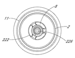
도 2g, 도 2h 및 도 2k에 도시되어 있는 바와 같이, 치료 기구(1)는 시스템 콘솔(102)에 위치될 수도 있는 폐기물 저장조로 폐기물 또는 유출물 액체(19)를 운반하기 위한 배출 또는 출구 라인(4)을 또한 포함할 수 있다. 흡입 포트(8) 또는 유체 출구는 중심축(Z)으로부터 오프셋된 챔버(6)의 벽을 따라 챔버(6)에 노출될 수 있다. 예를 들어, 도 2g에 도시되어 있는 바와 같이, 흡입 포트(8)는 접근 포트(18)에 대향하는 챔버(6)의 상부벽(17)을 따라 배치될 수 있다. 진공 펌프(도시되어 있지 않음)는 출구 라인(4)을 따라 진공력을 인가하여 흡입 포트(8)를 통해, 출구 라인(4)을 따라, 폐기물 저장조로 챔버(6) 외부로 폐기물 또는 유출물 액체(19)를 흡인할 수 있다. 몇몇 실시예에서, 단지 하나의 흡입 포트(8)가 제공될 수 있다. 그러나, 도 2h 및 도 2k의 실시예에 도시되어 있는 바와 같이, 기구(1)는 측방향으로 서로 대향하여 위치된 복수의(예를 들어, 2개) (예를 들어, 2개의) 흡입 포트를 포함할 수 있다. 몇몇 실시예에서, 2개 초과의 흡입 포트가 제공될 수 있다. 흡입 포트(8)는 예를 들어 중심축(Z)에 대해 대칭적으로 서로 대향하여 측방향으로 배치될 수 있다. 도시되어 있는 바와 같이, 흡입 포트(8)는 측벽(13)에서 또는 그 부근에서, 예를 들어, 챔버(6)의 중심축(Z)보다 측벽(13)에 더 가깝게 상부벽(17)을 통해 배치될 수 있다. 예시된 실시예에서, 흡입 포트(8)는 측벽(13)에 의해 적어도 부분적으로 맞접하거나 형성될 수 있다. 다른 실시예에서, 흡입 포트(8)는 측벽(13)으로부터 측방향으로 삽입될 수 있다. 또 다른 실시예에서, 흡입 포트(8)는 챔버(6)의 측벽(13) 상에 배치될 수 있다.2G , 2H and 2K ,
이에 따라, 다양한 실시예에서, 챔버(6)는 중심축(Z)에 대해 실질적으로 횡방향으로(예를 들어, 중심축에 대해 85° 내지 95° 범위의 각도로, 89° 내지 91°의 범위의 각도로, 또는 89.5° 내지 90.5°의 범위의 각도로) 연장하는 제1 평면에서 최대 측방향 치수를 가질 수 있다. 제1 평면은 벽의 경계를 따라 챔버의 벽에 의해 경계 한정될 수 있다. 제1 평면 상의 흡입 포트(8)의 투영부는 챔버(6)의 중심축(Z)보다 경계에 더 가까울 수 있다. 예를 들어, 예시된 실시예에서, 챔버(6)는 대략 원형의 저부 단면을 포함할 수 있고, 중심축(Z)에 대해 실질적으로 횡방향인 제1 평면은 대략 원형 경계에 의해 측벽(13)을 따라 경계 한정될 수 있다. 제1 평면 상의 흡입 포트(8)의 투영부는 중심축(Z)보다 대략 원형 경계에 더 가까울 수 있다.Accordingly, in various embodiments, the
도시되어 있는 바와 같이, 흡입 포트(8)는 세장형이고 만곡된(예를 들어, 콩팥 형상의) 개구를 포함할 수 있다. 흡입 포트(8)의 곡률은 몇몇 실시예에서 일반적으로 챔버(6)의 측벽(13)의 곡률과 합치할 수도 있다. 다른 실시예에서, 흡입 포트(8)는 만곡되지 않을 수도 있고 다각형(예를 들어, 직사각형)일 수도 있다. 유리하게는, 개구의 길이가 폭보다 더 큰 세장형 흡입 포트(8)의 사용은 큰 입자가 흡입 포트(8) 및/또는 출구 라인(4)을 막히게 하는 것을 방지할 수 있다. 몇몇 실시예에서, 흡입 포트(8)는 상부벽(17)과 동일 높이의 개구를 포함할 수 있다. 다른 실시예에서, 흡입 포트(8)는 챔버(6) 내로 부분적으로 돌출할 수 있다.As shown, the
몇몇 실시예에서, 압력파 발생기(10) 및 흡입 포트(들)(8)는 챔버(6)에 대해 성형되고 위치될 수 있어, 치료 절차에서 치료 기구(1)의 동작 중에, 치아의 치료 영역(예를 들어, 첨단에서 측정된 치아의 근관 내의)에서의 압력은 50 mmHg 내지 -500 mmHg 범위 내에서 유지될 수 있게 된다. 치료 영역에서의 압력을 원하는 범위 내에서 유지하는 것은 환자에 대한 통증의 위험을 감소시키고, 치근단 개구(115) 외부로 치근단측으로 액체의 압출을 방지하고, 그리고/또는 세정 효능을 개선할 수 있다. 예를 들어, 압력파 발생기(10) 및 흡입 포트(들)(8)는, 치료 절차에서 치료 기구(1)의 동작 중에, 첨단(114) 및 치근단 개구(115)에서 또는 그 부근에서 치근단 압력은 50 mmHg 미만, 5 mmHg 미만, -5 mmHg 미만, 예를 들어 -5 mmHg 내지 -200 mmHg의 범위 내, -5 mmHg 내지 -55 mmHg의 범위 내, 또는 -10 mmHg 내지-50 mmHg 범위 내에서 유지되도록 챔버(6)에 대해 성형되고 위치될 수 있다. 치근단 압력을 이들 범위 내에서 유지하는 것은 환자에 대한 통증의 위험을 감소시키고, 치근단 개구(115) 외부로 치근단측으로 액체의 압출을 방지하고, 그리고/또는 세정 효능을 개선할 수 있다.In some embodiments, the
몇몇 실시예에서, 치근단 압력을 조절하기 위해, 흡입 포트(8)는 노즐(9)로부터 원주방향으로 오프셋될 수 있다. 예를 들어, 예시된 실시예에서, 흡입 포트(8)는 약 90°만큼 노즐(9)로부터 원주방향으로 오프셋될 수 있다.In some embodiments, in order to adjust the apical pressure, the
또한, 챔버(6)는 폭(w)(예를 들어, 챔버(6)의 직경 또는 다른 주요 측방향 치수) 및 상부벽(17)으로부터 접근 포트(18)까지 연장하는 높이(h)를 가질 수 있다. 폭(w)과 높이(h)는 치근단 압력을 원하는 범위 내에서 유지하면서 효과적인 세정 결과를 제공하도록 선택될 수 있다. 다양한 실시예에서, 예를 들어, 챔버(6)의 폭(w)은 2 mm 내지 4 mm의 범위, 2.5 mm 내지 3.5 mm의 범위, 또는 2.75 mm 내지 3.25 mm의 범위(예를 들어, 약 3 mm)일 수 있다. 챔버(6)의 높이(h)는 약 1 mm 내지 30 mm의 범위, 약 2 mm 내지 10 mm의 범위, 또는 약 3 mm 내지 5 mm의 범위일 수 있다.The
압력파 발생기(10)(예를 들어, 노즐(9))는 치아를 치료하기에 충분한 유체 운동(24)을 발생시키는 위치에서 챔버(6)에 대해 위치될 수 있다. 도시되어 있는 바와 같이, 압력파 발생기(10)(예를 들어, 노즐(9)을 포함함)는 도시되어 있는 바와 같이 챔버(6) 외부에 배치될 수 있다(예를 들어, 챔버(6)로부터 오목하게 형성됨). 몇몇 실시예에서, 압력파 발생기(10)는 챔버(6)에 노출될 수 있지만(또는 동일 높이임) 챔버(6) 내로 연장되지 않을 수도 있다. 또 다른 실시예에서, 압력파 발생기(10)의 적어도 일부는 챔버(6) 내로 연장될 수도 있다. 압력파 발생기(10)(예를 들어, 노즐(9)을 포함함)는 흡입 포트(8)의 아래 또는 원위측에 위치될 수 있다. 더욱이, 예시된 실시예에서, 제트(20)는 중심축(Z)에 실질적으로 수직으로 지향될 수 있다(제트 축(X)과 중심축(Z) 사이의 각도가 대략 90°가 되도록). 제트(20)는 챔버의 중심축(Z)에 근접하여 통과할 수 있는데, 예를 들어 챔버(6)의 측방향 중심 영역을 통과할 수 있다. 예를 들어, 몇몇 실시예에서, 제트 축(X) 또는 액체 제트(20)는 챔버의 중심축(Z)과 교차할 수 있다. 몇몇 실시예에서, 제트(20)는 챔버(6)의 측방향 중심 영역을 통과할 수도 있지만 중심축(Z)으로부터 약간 오프셋될 수도 있다. 예를 들어, 중심축(Z)은 제트 축(X)에 대해 실질적으로 횡방향인 제2 평면에 놓일 수 있다(예를 들어, 제2 평면은 85° 내지 95°의 범위, 89° 내지 91°의 범위, 또는 89.5° 내지 90.5°의 범위에서 제트 축(X)에 대해 각형성될 수 있음). 스트림 또는 제트 축(X)은 측벽(13)보다 중심축(Z)에 더 가까운 위치에서 제2 실질적으로 횡방향 평면과 교차할 수 있다.A pressure wave generator 10 (eg, nozzle 9 ) may be positioned relative to
이에 따라, 전술된 바와 같이, 챔버(6)는 중심축(Z)에 대해 실질적으로 횡방향으로 연장하는 제1 평면에서 최대 측방향 치수를 가질 수 있고, 중심축(Z)은 스트림 또는 제트 축(X)에 대해 실질적으로 횡방향으로 연장하는 제2 평면에 놓일 수 있다. 제1 평면은 벽의 경계를 따라 챔버(6)의 벽(예를 들어, 측벽(13))에 의해 경계 한정될 수 있다. 전술된 바와 같이, 흡입 포트(8)는 중심축(Z)보다 경계(예를 들어, 몇몇 실시예에서 측벽(13))에 더 가까울 수 있다. 흡입 포트(8)는 또한 스트림 또는 제트 축(X)이 제2 평면과 교차하는 위치보다 경계에 더 가까울 수도 있다. 또한, 스트림 또는 제트 축(X)이 제2 평면과 교차하는 위치는 흡입 포트(8)(또는 제2 평면 상의 흡입 포트(8)의 투영부)보다 중심축(Z)에 더 가까울 수 있다. 본 명세서에 예시된 벽은 상부벽 및 그로부터 연장하는 측벽을 포함할 수 있지만, 다른 실시예에서, 벽은 단일의 만곡된 벽을 포함할 수 있거나, 임의의 다른 적합한 형상을 가질 수 있다.Accordingly, as described above, the
전술된 바와 같이, 통기구(7)는 플랫폼(2)을 통해 제공될 수 있고 주위 공기에 노출될 수 있다. 통기구(7)는 흡입 포트(8)에 유동적으로 연결되는 배출 라인(4)과 유체 연통할 수 있다. 통기구(7)는 흡입 포트(8)의 하류의 위치에서 배출 또는 출구 라인(4)을 따라 배치될 수 있다. 통기구(7)는 챔버(6) 및 치료 영역의 과압축을 유리하게 방지하거나 감소시킬 수 있다. 예를 들어, 외부 환경으로부터의 주위 공기는 출구 라인(4)을 따라 제거된 유출물 액체(19)와 함께 비말동반될 수 있다. 통기구(7)는 정적 음압(negative pressure)의 인가를 허용함으로써 치료 영역 내의 압력을 조절할 수 있다. 예를 들어, 통기구(7)의 크기는 치료 영역에서 원하는 양의 정적 음압을 제공하도록 선택될 수 있다. 통기구(7)는 주위 공기가 챔버(6) 및/또는 치아(110)의 치료 영역에 진입하는 것을 방지하기 위해 출구 라인(4)을 따른 위치에 위치될 수 있다. 통기 유체 플랫폼에 관한 부가의 상세는 그 전체 내용이 모든 목적을 위해 그대로 본 명세서에 참조로서 합체되어 있는 미국 특허 제9,675,426호 전체에 걸쳐 발견될 수 있다.As mentioned above, vents 7 may be provided through
유리하게는, 도 2a 내지 도 2k의 실시예 및 유사한 실시예는 전체 치료 영역의 철저한 세정을 제공하기 위해 충분한 유체 운동 및 압력파를 생성할 수 있다. 압력파 발생기(10), 챔버(6), 흡입 포트(10), 통기구(7) 등과 같은 구성요소는, 다른 디바이스와 비교할 때 효과적인 치료(예를 들어, 효과적인 세정 또는 충전), 개선된 압력 조절(예를 들어, 치료 영역에서의 압력을 적합한 범위 내에서 유지함) 및 개선된 환자 결과를 제공하기 위해, 예시된 실시예에 도시되고 설명된 바와 같이 배열될 수 있다.Advantageously, the embodiment of FIGS. 2A-2K and similar embodiments can generate sufficient fluid motion and pressure waves to provide thorough cleaning of the entire treatment area. Components such as
본 명세서에 개시된 치료 기구(1)의 실시예는 그 전체 내용이 모든 목적을 위해 그대로 본 명세서에 첨부되고 참조로서 합체되어 있는 미국 특허 제10,363,120호 전체에 걸쳐 도시되고 설명된 특징과 조합하여 사용될 수 있다.Embodiments of the
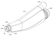
도 3a 내지 도 3c는 다른 실시예에 따른 치료 기구(1)를 도시하고 있다. 달리 언급되지 않으면, 도 3a 내지 도 3c의 구성요소는 도 2a 내지 도 2k의 유사한 번호의 구성요소와 동일하거나 일반적으로 유사할 수도 있다. 치료 기구(1)는 핸드피스(12) 및 핸드피스(12)에 연결되거나 함께 형성된 유체 플랫폼(2)을 포함할 수 있다. 그러나, 도 2a 내지 도 2k의 실시예와는 달리, 핸드피스(12)는 콘트라앵글 핸드피스 본체(21)를 포함한다. 콘트라앵글 핸드피스 본체(21)는 상향으로 만곡될 수 있는데, 이는 임상의에 의한 핸드피스(12)의 조작성 및/또는 핸들링을 개선할 수 있다.3a to 3c show a
도 4a는 다양한 실시예에 따른, 치료 기구(1)의 개략 저면 우측 사시도이다. 도 4b는 도 4a의 치료 기구(1)의 개략 평면 좌측 사시도이다. 도 4c는 도 4a 및 도 4b의 치료 기구의 개략 측면 사시 단면도이다. 달리 언급되지 않으면, 도 4a 내지 도 4c의 구성요소는 도 2a 내지 도 2k의 유사한 번호의 구성요소와 동일하거나 일반적으로 유사할 수도 있다. 도 4a 및 도 4b에서, 핸드피스 본체는 치료 기구의 다른 구성요소를 쉽게 도시하기 위해 숨겨져 있다. 도 4a 내지 도 4c의 실시예에서, 흡입 포트(8)는 다각형(예를 들어, 직사각형)의 세장형 개구를 포함할 수도 있다. 또한, 도 4a 내지 도 4c의 실시예에서, 접근 포트(18)는 접근 포트(18) 위에 또는 근위측에 배치된 챔버(6)의 것보다 더 작은 직경 또는 주요 치수를 가질 수도 있다. 다른 실시예에서, 접근 포트(18)는 접근 포트(18) 위에 또는 근위측에 배치된 챔버(6)의 것보다 크거나 실질적으로 동일한 직경 또는 주요 치수를 가질 수도 있다.4A is a schematic bottom right perspective view of a
III. 제거 가능한 팁 디바이스를 갖는 치료 기구의 예III. Example of a treatment instrument with a removable tip device
도 5는 다양한 실시예에 따른 치과 치료 기구(1)의 개략도이다. 달리 언급되지 않으면, 도 5의 구성요소는 도 2a 내지 도 2k, 도 3a 내지 도 3c, 또는 도 4a 내지 도 4c의 유사한 번호의 구성요소와 동일하거나 일반적으로 유사할 수도 있다. 치과 치료 기구(1)는 팁 디바이스(11) 및 핸드피스 본체(12a)를 갖는 핸드피스(12)를 포함할 수 있다. 팁 디바이스(11)는 핸드피스 본체(12a)의 원위 부분에 제거 가능하게 연결될 수 있다. 다양한 실시예에서, 핸드피스 본체(12a)는 핸드피스 본체(12a)를 팁 디바이스(11)에 제거 가능하게 연결하는 커넥터(225)를 포함할 수 있다. 팁 디바이스(11)는 팁 디바이스(11)를 핸드피스 본체(12a)에 제거 가능하게 연결하는 커넥터(226)를 포함할 수 있다. 커넥터(225)는 팁 디바이스(11)를 핸드피스 본체(12a)에 제거 가능하게 결합하도록 커넥터(226)와 결합될 수 있다. 팁 디바이스(11)는 치아를 치료하기 위해(예를 들어, 치아의 치료 영역을 세정 및/또는 충전하기 위해) 치료 영역에 대해 또는 그 위에 위치되도록 구성될 수 있다.5 is a schematic diagram of a
몇몇 실시예에서, 커넥터(225)는 커넥터(226)의 대응 내부 나사산과 맞물리는 외부 나사산을 포함할 수 있다. 몇몇 실시예에서, 커넥터(225)는 커넥터(226)의 대응 외부 나사산과 맞물리는 내부 나사산을 포함할 수 있다. 몇몇 실시예에서, 커넥터(225)는 커넥터(226)의 복수의 리셉터클과 맞물리기 위한 복수의 돌출부를 포함할 수 있다. 몇몇 실시예에서, 커넥터(225)는 커넥터(226)의 복수의 리셉터클과 맞물리도록 반경방향 벽으로부터 연장하는 복수의 돌출부를 포함할 수 있다.In some embodiments,
몇몇 실시예에서, 커넥터(225)는 퀵 커넥트 커플링을 통해 커넥터(226)에 결합될 수 있다. 몇몇 실시예에서, 퀵 커넥트 커플링은 복수의 수축 가능한 볼 베어링을 포함한다. 몇몇 실시예에서, 퀵 커넥트 커플링은 활주 칼라를 포함한다. 몇몇 실시예에서, 커넥터(225 또는 226) 중 하나 상의 활주 칼라는 연결 축을 따라 활주하여 볼 베어링이 수축하는 것을 허용할 수 있다. 칼라가 전방으로 활주될 때, 볼 베어링은 다른 커넥터(225 또는 226) 상의 특징부 내로 압입되어 이에 의해 일회용 팁의 탈착을 방지할 수 있다. 몇몇 실시예에서, 퀵 커넥트 커플링은 핸드피스 본체(12a) 상에 능동 커넥터(예를 들어, 볼 베어링을 갖는 칼라) 또는 수동 커넥터(예를 들어, 베어링과 인터페이스하는 고정된 기하학 구조)로 구현될 수 있다. 몇몇 실시예에서, 핸드피스 본체(12a)는 유리하게는 효과적인 오염 제거 및 멸균을 용이하게 하기 위한 수동 커넥터를 포함할 수 있다.In some embodiments, the
몇몇 실시예에서, 커넥터(225)는 스냅 끼워맞춤을 통해 커넥터(226)에 결합될 수 있다. 커넥터(225) 또는 커넥터(226)는 특징부를 가압하거나 압착함으로써 눌러질 수 있는 하나 이상의 스냅 특징부를 포함할 수 있다. 다른 커넥터(225 또는 226) 상의 상보적인 정합 구성요소는 스냅 특징부가 맞물리는 특징부 또는 언더컷을 포함할 수 있다.In some embodiments, the
몇몇 실시예에서, 커넥터(226)는 커넥터(225)의 대응 외부 나사산과 맞물리는 내부 나사산을 포함할 수 있다. 몇몇 실시예에서, 커넥터(226)는 커넥터(225)의 대응 내부 나사산과 맞물리는 외부 나사산을 포함할 수 있다. 몇몇 실시예에서, 커넥터(226)는 커넥터(225)의 대응 돌출부와 맞물리기 위한 복수의 리셉터클을 포함할 수 있다. 몇몇 실시예에서, 커넥터(226)는 커넥터(225)의 반경방향 벽으로부터 연장하는 대응 돌출부와 맞물리기 위한 복수의 리셉터클을 포함할 수 있다. 몇몇 실시예에서, 커넥터(226)는 커넥터(225)의 대응 리셉터클과 맞물리기 위한 복수의 돌출부를 포함한다.In some embodiments,
따라서, 다양한 실시예에서, 팁 디바이스(11)는 치료 절차 전에 핸드피스 본체(12a)에 연결될 수 있다. 팁 디바이스(11)가 핸드피스 본체(12a)에 연결된 후, 임상의는 세정 절차와 같은 치료 절차를 수행할 수 있다. 치료 절차 후, 임상의는 핸드피스 본체(12a)로부터 치료 팁 디바이스(11)를 제거할 수 있다.Thus, in various embodiments, the
다양한 실시예에서, 핸드피스 본체(12a)는 다수의 절차, 예를 들어 미리 결정된 수의 절차에서 사용될 수 있다. 다양한 실시예에서, 핸드피스 본체(12a)는 다수의 팁 디바이스(11)에 연결하도록 구성될 수 있다. 몇몇 실시예에서, 핸드피스 본체(12a)는 동일한 구성을 갖는 다수의 팁 디바이스(11)에 연결하도록 구성될 수 있다. 다른 실시예에서, 핸드피스 본체(12a)는 상이한 구성을 갖는 다수의 팁 디바이스(11)에 연결하도록 구성될 수 있다. 예를 들어, 몇몇 실시예에서, 핸드피스 본체(12a)는 상이한 유형의 치아의 치료를 위해 구성된 다수의 팁 디바이스(11), 예를 들어 대구치의 치료를 위한 제1 팁 디바이스 및 전치 또는 소구치의 치료를 위한 제2 팁 디바이스에 연결할 수 있다. 몇몇 실시예에서, 핸드피스 본체(12a)는 상이한 유형의 치료 영역의 치료를 위해 구성된 다수의 팁 디바이스, 예를 들어 근관의 치료를 위한 제1 팁 디바이스 및 외부 우식 영역의 치료를 위한 제2 팁 디바이스에 연결할 수 있다.In various embodiments, the
다양한 실시예에서, 팁 디바이스(11)는 일회용일 수 있다. 유리하게는, 일반적으로 재사용 가능한 핸드피스 본체(12a)와 함께 일회용 팁 디바이스(11)를 제공하는 것은 임상의가 단일 사용 후 핸드피스 본체(12a)를 폐기하는 것과 연관된 비용을 감소시키는 것을 가능하게 할 수 있다.In various embodiments, the
다양한 실시예에서, 팁 디바이스(11)는 치아의 영역에 대해 위치되도록 구성된 유체 플랫폼(2)을 포함할 수 있다. 몇몇 실시예에서, 유체 플랫폼(2)은 치아의 치료 영역에 대해, 예를 들어 치아의 근관에 대한 접근을 제공하는 접근 개구 위에 위치되도록 크기 설정되고 선택될 수 있다(예를 들어, 그 각각의 전체 내용이 모든 목적을 위해 그대로 본 명세서에 참조로서 합체되어 있는 미국 특허 제9,675,426호 및 미국 특허 제10,363,120호 참조). 다른 실시예에서, 유체 플랫폼(2)은 치아의 외부면 상의 우식 영역 위에 위치될 수 있다(예를 들어, 그 전체 내용이 모든 목적을 위해 그대로 본 명세서에 참조로서 합체되어 있는 미국 특허 공개 제2015/0044632호 참조).In various embodiments, the
유체 플랫폼(2)은 치아의 치료 영역과 유체 연통하도록 챔버(6)를 적어도 부분적으로 형성할 수 있다. 몇몇 실시예에서, 유체 플랫폼(2)은 치료 절차 중에 챔버(6) 내에 유체를 실질적으로 보유하기 위해 치아에 적용되도록 크기 설정될 수 있다. 몇몇 실시예에서, 치료 영역은 우식 영역일 수 있다. 다른 실시예에서, 치료 영역은 근관일 수 있다. 몇몇 실시예에서, 챔버(6)의 적어도 일부는 유체 플랫폼이 치아의 영역에 대해 위치될 때 치아의 외부에 위치된다.The
몇몇 실시예에서, 유체 플랫폼(2)은 치료 절차 중에 챔버(6) 내에 유체를 실질적으로 보유하기 위해 대구치에 적용되도록 크기 설정될 수 있다. 몇몇 실시예에서, 유체 플랫폼(2)은 치료 절차 중에 챔버(6) 내에 유체를 실질적으로 보유하기 위해 전치 또는 소구치에 적용되도록 크기 설정될 수 있다.In some embodiments, the
몇몇 실시예에서, 유체 플랫폼(2)은 챔버(6)가 치아의 외부면에서 우식 영역 주위에 봉입된 체적을 형성하도록 우식 영역 위에 치아의 외부면에 대해 위치되고 그에 대해 적어도 부분적으로 밀봉하도록 크기 설정된다.In some embodiments, the
몇몇 실시예에서, 유체 플랫폼(2)은 유체 리테이너 또는 캡, 및 치료 영역의 부분과 접촉하도록 구성된 접촉 부재를 포함할 수 있다. 사용 중에, 임상의는 치료 영역을 실질적으로 밀봉하기 위해 치료 영역 상에 접촉 부재(가요성 부재, 스펀지 등을 포함할 수 있음)를 가압할 수 있다. 몇몇 실시예에서, 임상의는 치료 영역을 실질적으로 밀봉하기 위해 유체 플랫폼(2)을 치료 영역에 접착하거나 다른 방식으로 연결할 수 있다.In some embodiments, the
다양한 실시예에서, 팁 디바이스(11)는 치아의 치료 영역에 제공된 유체 내에 압력파 및/또는 유체 운동을 발생하도록 구성된 압력파 발생기(10)를 포함할 수 있다. 몇몇 실시예에서, 압력파 발생기는 압력파 발생기(10)로부터 이격한 위치에서 압력파 및/또는 유체 운동을 발생할 수 있다. 몇몇 실시예에서, 압력파 발생기(10)는 플랫폼(2)에 결합될 수 있다.In various embodiments, the
다양한 실시예에서, 압력파 발생기(10)는 그 전체 내용이 모든 목적을 위해 그대로 본 명세서에 참조로서 합체되어 있는 적어도 미국 특허 제9,675,426호, 미국 특허 제10,363,120호, 또는 미국 특허 공개 제2015/0044632호에 설명된 바와 같이, 치아의 치료 영역(예를 들어, 근관 또는 우식 영역)을 세정하는 데 사용될 수 있다. 다양한 실시예에서, 압력파 발생기(10)는 그 전체 내용이 모든 목적을 위해 그대로 본 명세서에 참조로서 합체되어 있는 적어도 미국 특허 제9,877,801호에 설명된 바와 같이, 치아의 치료 영역(예를 들어, 근관 또는 우식 영역)을 충전하는 데 사용될 수 있다.In various embodiments, the
몇몇 실시예에서, 압력파 발생기(10)는 액체 제트 디바이스를 포함할 수 있다. 액체 제트 디바이스는 챔버(6) 내의 및/또는 치료 영역 내의 액체와 상호 작용하여 치료 영역 내에 압력파 및 유체 운동을 발생할 수 있는 액체 제트를 생성할 수 있다. 발생된 압력파 및 유체 운동은 그 전체 내용이 모든 목적을 위해 그대로 본 명세서에 참조로서 합체되어 있는 미국 특허 제9,675,426호, 미국 특허 제10,363,120호, 미국 특허 공개 제2015/0044632호에 설명된 것들과 같은, 다양한 절차에서 치료 영역을 세정하는 데 사용될 수 있다. 몇몇 배열에서, 발생된 압력파 및 유체 운동은 그 전체 내용이 모든 목적을 위해 그대로 본 명세서에 참조로서 합체되어 있는 미국 특허 제9,877,801호에 설명된 절차와 같이, 치료 영역을 충전하는 데 사용될 수 있다.In some embodiments, the
몇몇 실시예에서, 압력파 발생기(10)는 레이저 디바이스를 포함할 수 있다. 레이저 디바이스는 챔버(6) 내의 및/또는 치료 영역 내의 액체와 상호 작용하여 치료 영역 내에 압력파 및 유체 운동을 발생할 수 있는 레이저 빔을 생성할 수 있다. 발생된 압력파 및 유체 운동은 그 전체 내용이 모든 목적을 위해 그대로 본 명세서에 참조로서 합체되어 있는 미국 특허 제9,675,426호, 미국 특허 제10,363,120호, 미국 특허 공개 제2015/0044632호에 설명된 것들과 같은, 다양한 절차에서 치료 영역을 세정하는 데 사용될 수 있다. 몇몇 배열에서, 발생된 압력파 및 유체 운동은 그 전체 내용이 모든 목적을 위해 그대로 본 명세서에 참조로서 합체되어 있는 미국 특허 제9,877,801호에 설명된 절차와 같이, 치료 영역을 충전하는 데 사용될 수 있다.In some embodiments, the
다른 실시예에서, 압력파 발생기(10)는 예를 들어 그 각각의 전체 내용이 모든 목적을 위해 그대로 본 명세서에 참조로서 합체되어 있는 미국 특허 제9,675,426호, 미국 특허 제10,363,120호, 미국 특허 제9,877,801호, 미국 특허 제9,504,536호 및 미국 특허 공개 제2015/0044632호에 설명된 다른 유형의 압력파 발생기를 포함할 수 있다. 압력파 발생기(10)는 그 각각의 전체 내용이 모든 목적을 위해 그대로 본 명세서에 참조로서 합체되어 있는 미국 특허 제9,675,426호, 미국 특허 번호 제10,363,120호, 미국 특허 제9,877,801호, 미국 특허 제9,504,536호 및 미국 특허 공개 제2015/0044632호에 설명된 바와 같이, 다중 주파수에서 광대역 압력파를 발생하도록 배열될 수 있는데, 이는 치료 영역을 세정하거나 충전하는 데 유익할 수 있다. 다양한 실시예에서, 탈가스된 치료 액체는 예를 들어, 치료 영역의 세정을 향상시키기 위해 압력파 발생기(10)와 협력하여 사용될 수 있다.In other embodiments, the
몇몇 실시예에서, 압력파 발생기(10)는 유체 플랫폼(2)이 치아에 적용될 때 치아의 외부에 위치될 수 있다. 몇몇 실시예에서, 유체 플랫폼(2)이 우식 영역 위의 치아의 외부면에 대해 위치되고 그에 대해 적어도 부분적으로 밀봉하도록 크기 설정될 때, 압력파 발생기는 유체 플랫폼이 치아의 외부면에 결합될 때 우식 영역 외부에 위치될 수 있다. 근관 치료 절차와 같은 몇몇 실시예에서, 압력파 발생기(10)는 치아의 챔버 내로 연장될 수 있다. 몇몇 실시예에서, 압력파 발생기(10)는 치아의 치료 영역 내로 연장될 수 있다. 몇몇 실시예에서, 예를 들어 치아가 전치 또는 소구치일 때, 유체 플랫폼(2)은 치아 내의 미리 형성된 측면 개구를 통해 전치 또는 소구치와 상호 작용하도록 구성될 수 있고, 압력파 발생기는 유체 플랫폼이 전치 또는 소구치와 상호 작용할 때 전치 또는 소구치 외부에 위치될 수 있다.In some embodiments, the
다양한 실시예에서, 핸드피스 본체(12a)는 팁 디바이스(11)에 유체, 전기 및/또는 데이터 통신을 제공할 수 있다. 몇몇 실시예에서, 핸드피스 본체(12a)는 팁 디바이스(11)의 하나 이상의 도관과 연통하는 하나 이상의 도관을 포함할 수 있다. 핸드피스 본체(12a)의 도관은 팁 디바이스(11)의 도관에 유체, 전기 및/또는 데이터 통신을 제공할 수 있다.In various embodiments,
도 6은 다양한 실시예에 따른 치과 치료 기구(1)의 개략도이다. 달리 언급되지 않으면, 도 6의 구성요소는 도 2a 내지 도 2k, 도 3a 내지 도 3c, 도 4a 내지 도 4c, 또는 도 5의 유사한 번호의 구성요소와 동일하거나 일반적으로 유사할 수도 있다. 도 6에 도시되어 있는 바와 같이, 몇몇 실시예에서, 핸드피스 본체(12a)는 핸드피스 본체(12a)가 팁 디바이스(11)에 결합될 때 유체 입구 라인(5)을 형성하기 위해 팁 디바이스(11)의 도관(5b)과 연통하도록 구성된 도관(5a)을 포함할 수 있다.6 is a schematic diagram of a
몇몇 실시예에서, 라인(5)은 압력파 발생기에 결합될 수 있다. 몇몇 실시예에서, 라인(5)은 유체 유입 라인 또는 유체 입구 라인일 수 있다. 예를 들어, 압력파 발생기(10)가 액체 제트 디바이스를 포함하는 실시예에서, 라인(5)은 액체 제트 디바이스로 유체를 전달할 수 있다.In some embodiments,
다양한 실시예에서, 팁 디바이스(11)는 챔버(6)로부터 유체를 운반하기 위해 하나 이상의 유체 출구 또는 흡입 포트(8)를 포함할 수 있다. 흡입 포트(들)(8)는 흡입 펌프(예를 들어, 콘솔 내에 위치될 수도 있음)와 연통할 수 있다. 흡입 펌프가 활성일 때, 액체는 포트(들)(8)를 통해 출구 라인(4)으로 챔버(6) 외부로 인출될 수 있고, 출구 라인은 예를 들어 콘솔 내에 위치될 수도 있는 폐기물 용기로 제거된 액체를 운반할 수 있다.In various embodiments, the
몇몇 실시예에서, 핸드피스 본체(12a)는 핸드피스 본체(12a)가 팁 디바이스(11)에 결합될 때 라인(4)을 형성하기 위해 팁 디바이스(11)의 도관(4b)과 연통하도록 구성된 도관(4a)을 포함할 수 있다. 라인(4)은 포트(들)(8)에 결합되어 유체 출구 라인(4)을 형성할 수 있다.In some embodiments,
다양한 실시예에서, 팁 디바이스(11)는 주위 공기가 포트(들)(8)의 하류에서 라인(4)으로 흡인되는 것을 허용하도록 구성된 하나 이상의 통기구(7)를 포함할 수 있다. 통기구(들)(7)는 유리하게는 예를 들어, 그 전체 내용이 모든 목적으로 그대로 본 명세서에 참조로서 합체되어 있는 미국 특허 제9,675,426호, 미국 특허 제10,363,120호 및 미국 특허 공개 제2015/0044632호에 설명된 바와 같이, 압력 조절 기능을 제공할 수 있다.In various embodiments, the
다양한 실시예에서, 핸드피스 본체(12a)는 하나 이상의 밀봉부(224)를 포함할 수 있다. 밀봉부(224)는 핸드피스 본체(12a)와 팁 디바이스(11) 사이에 유체 밀봉부를 제공할 수 있다. 몇몇 실시예에서, 하나 이상의 밀봉부(224)는 하나 이상의 O-링을 포함할 수 있다. 몇몇 실시예에서, 하나 이상의 밀봉부(224)는 하나 이상의 면 밀봉부를 포함할 수 있다. 몇몇 실시예에서, 하나 이상의 밀봉부(224)는 하나 이상의 엘라스토머 슬리브를 포함할 수 있다.In various embodiments, the
다양한 실시예에서, 치과 치료 기구(1)는 핸드피스 본체(12a)에 대해 고정된 배향으로 원위 팁 디바이스(11)를 제거 가능하게 고정하기 위한 로킹 메커니즘(231)을 포함할 수 있다. 특정 실시예에서, 팁 디바이스(11)는 핸드피스 본체(12a)에 대해 고정된 배향으로 원위 팁 디바이스(11)를 고정하기 위해 핸드피스 본체(12a)의 대응 로킹 부재(230)와 결합하도록 구성된 로킹 부재(229)를 포함할 수 있다. 몇몇 실시예에서, 로킹 부재(230)는 커넥터(225)에 또는 그 부분에 결합될 수 있다. 몇몇 실시예에서, 로킹 부재(229)는 커넥터(226)에 또는 그 부분에 결합될 수 있다.In various embodiments, the
몇몇 실시예에서, 로킹 부재(230)는 로킹 부재(229)의 하나 이상의 리세스 내에 수용되도록 위치된 하나 이상의 돌출부를 포함할 수 있다. 몇몇 실시예에서, 돌출부는 반구형 돌출부일 수 있다. 몇몇 실시예에서, 로킹 부재(229)는 로킹 부재(230)의 하나 이상의 리세스 내에 수용되도록 위치된 하나 이상의 돌출부를 포함할 수 있다. 몇몇 실시예에서, 돌출부는 반구형 돌출부일 수 있다. 몇몇 실시예에서, 로킹 부재(229)는 로킹 부재(230)의 슬롯 내에 수용되도록 위치된 활주 로킹 장치를 포함할 수 있다. 몇몇 실시예에서, 로킹 부재(230)는 로킹 부재(229)의 슬롯 내에 수용되도록 위치된 활주 로킹 장치를 포함할 수 있다. 몇몇 실시예에서, 로킹 메커니즘(231)은 핸드피스 본체(12a)에 대해 고정된 배향으로 팁 디바이스(11)를 고정하도록 구성된 하나 이상의 볼 멈춤쇠를 포함할 수 있다.In some embodiments, the locking
몇몇 실시예에서, 커넥터(225, 226) 사이의 연결부는 적어도 10,200 psi 및 적어도 15,000 psi의 압력을 견디는 것이 가능할 수 있다. 몇몇 실시예에서, 커넥터(225, 226) 사이의 연결부는 입구(5)가 압축되는 동안 그 자신이 나사 풀림되거나 다른 방식으로 탈착되지 않도록 충분히 고정될 수 있다. 다른 실시예에서, 예를 들어, 커넥터(225, 226)가 나사산인 몇몇 실시예에서, 로킹 메커니즘(231)은 커넥터(225, 226)의 탈착 능력을 제한하거나 방지하기 위해 채용될 수도 있다. 몇몇 실시예에서, 커넥터(225, 226) 및 밀봉부(224)는 팁 디바이스(11)의 완전한 탈착 전에 밀봉부가 파괴되도록 설계될 수 있다. 이러한 메커니즘은 막힘 또는 폐색의 경우에 라인(5) 내에 저장된 압력이 팁 디바이스(11)의 완전한 기계적 탈착 전에 해제되는 것을 보장할 수 있다.In some embodiments, the connection between
몇몇 실시예에서, 팁 디바이스(11)는 팁 디바이스(11)와 연관된 고유 식별 정보를 저장하는 추적 메커니즘 또는 통신 디바이스(219)를 포함할 수 있다. 통신 디바이스는 무선 주파수 식별 태그(RFID), 바코드, 빠른 응답(QR) 코드 또는 전기적 소거 가능 프로그램 가능 판독 전용 메모리(EEPROM) 중 하나 이상일 수 있다. 그 전체 내용이 모든 목적을 위해 그대로 본 명세서에 참조로서 합체되어 있는 미국 특허 제9,504,536호에 설명된 바와 같이, 통신 디바이스(219)는 판독기와 무선으로 또는 다른 방식으로 통신할 수 있는데, 판독기는 팁 디바이스(11) 및/또는 치료 절차의 상태를 모니터링하도록 구성된 처리 회로를 포함할 수 있다. 다양한 실시예에서, 시스템은 단지 인증된 팁 디바이스(11)만이 핸드피스 본체(12a)와 함께 사용될 수도 있는 것을 보장하도록 구성될 수 있다. 다양한 실시예에서, 시스템은 팁 디바이스(11)가 단일 절차에서만 사용되는 것을 보장하도록 구성될 수 있다. 다른 실시예에서, 시스템은 얼마나 많은 절차에서 팁 디바이스(11)가 사용되었는지를 결정하도록 구성될 수 있다. 통신 디바이스(219)는 그 전체 내용이 모든 목적을 위해 그대로 본 명세서에 참조로서 합체되어 있는 미국 특허 제9,504,536호에 개시된 RFID 디바이스와 관련하여 설명된 것들을 포함하여, 다양한 다른 기능을 담당할 수 있다. 유사하게, 특정 실시예에서, 핸드피스 본체(12a)는 판독기와 무선으로 또는 다른 방식으로 통신할 수 있는 추적 메커니즘 또는 통신 디바이스를 포함할 수 있는데, 판독기는 핸드피스 본체(12a) 및/또는 치료 절차의 상태를 모니터링하도록 구성된 처리 회로를 포함할 수 있다. 특정 실시예에서, 통신 디바이스(219)는 콘솔이 팁 디바이스(11)의 이전 사용을 검출할 수 있게 하는 데이터를 제공하기 위해 기입 가능하거나 프로그램 가능할 수 있다. 특정 실시예에서, 통신 디바이스(219)는 팁 디바이스(11)에, 팁 디바이스(11)를 위한 보호 커버에, 또는 팁 디바이스(11)의 패키징에 통합될 수 있다.In some embodiments, the
도 7은 압력파 발생기(10)가 레이저 디바이스를 포함하는 다양한 실시예에 따른 치과 치료 장치 또는 기구(1)의 개략도이다. 달리 언급되지 않으면, 도 7의 구성요소는 도 2a 내지 도 2k, 도 3a 내지 도 3c, 도 4a 내지 도 4c, 도 5, 또는 도 6의 유사한 번호의 구성요소와 동일하거나 일반적으로 유사할 수도 있다. 도 7에 도시되어 있는 바와 같이 그리고 전술된 바와 같이, 도관(5a, 5b)은 치료 영역에 치료 액체(예를 들어, 세정 액체)를 전달할 수 있다. 또한, 도 7에서, 광학 입력 라인(65)은 핸드피스 본체(12a) 내의 제1 광학 입력 라인(65a) 및 팁 디바이스 내의 제2 광학 입력 라인(65b)을 포함할 수 있다. 광학 입력 라인(65a, 65b)은 광학 커플러(233)에 의해 결합된 광 섬유를 포함할 수 있다. 몇몇 실시예에서, 입력 라인(65a, 65b) 중 하나 또는 모두는 도파로, 광 섬유 등일 수 있다. 광학 커플러(233)는 광 섬유 커넥터, 스프링 로딩 커넥터, 인덱스 정합 재료, 나사형 커넥터, 스냅형 커넥터, 푸시-풀 커플링, 베이어닛 커넥터, 키형 커넥터, 클립 커넥터, 또는 광학 입력 라인(65a, 65b)을 결합하기 위한 임의의 다른 적합한 유형의 광학 커플러(233)일 수 있다. 몇몇 실시예에서, 압력파 발생기(10)는 제2 입력 라인(65b)의 원위 부분에 원위 팁을 포함할 수 있다. 예를 들어, 원위 섬유 팁은 원추형 팁, 또는 임의의 다른 적합하게 성형된 광 섬유 팁을 포함할 수 있다. 레이저 광은 입력 라인(65a, 65b)을 따라 전파될 수 있고 압력파 발생기(10)의 원위 팁을 통해 챔버(6) 내에 보유된 액체 내로 방출될 수 있다. 몇몇 실시예에서, 액체 내로 방출된 전자기 에너지는 치아를 치료하기 위해 치료 영역을 통해 전파하는 광음향파를 생성할 수 있다. 도 7에는 도시되어 있지 않지만, 도 7의 유체 플랫폼(2)은 유출물 또는 유출 유체를 치료 영역 및 챔버 외부로 그리고 출구 라인(4)을 따라 폐기물 저장조로 운반하는 흡입 포트(8)를 또한 포함할 수 있다. 게다가, 도 7에는 도시되어 있지 않지만, 유체 플랫폼(2)은 주위 공기에 노출되고 흡입 포트(8)의 하류에서 출구 라인(4)과 유체 연통하는 통기구(7)를 포함할 수 있다.7 is a schematic diagram of a dental treatment apparatus or
다양한 실시예에서, 핸드피스 본체(12a)는 콘솔 또는 다른 디바이스와 유체 연통하는 하나 이상의 도관에 연결하는 근위 커넥터를 포함할 수 있다. 근위 커넥터는 도관 및 콘솔과의 유체, 전기 및/또는 데이터 통신을 제공할 수 있다. 본 명세서에 개시된 치료 기구(1)의 부분에 대한 부가의 상세는 그 각각의 전체 내용이 모든 목적을 위해 그대로 본 명세서에 참조로서 합체되어 있는 미국 특허 제9,675,426호, 미국 특허 제10,363,120호, 미국 특허 제9,877,801호, 미국 특허 제9,504,536호 및 미국 특허 공개 제2015/0044632호 전체에 걸쳐 발견될 수도 있다. 예를 들어, 그 각각의 전체 내용이 모든 목적을 위해 그대로 본 명세서에 참조로서 합체되어 있는 미국 특허 제9,675,426호 및 미국 특허 제10,363,120호에 도시되어 있는 디바이스와 유사하게, 기구(1)는 치아의 근관을 세정하는 데 사용될 수 있다. 치아는 몇몇 실시예에서 대구치를 포함할 수 있다(예를 들어, 그 전체 내용이 모든 목적을 위해 그대로 본 명세서에 참조로서 합체되어 있는 미국 특허 제9,675,426호 참조). 다른 실시예에서, 치아는 몇몇 실시예에서 전치 또는 소구치를 포함할 수 있다(예를 들어, 그 전체 내용이 모든 목적을 위해 그대로 본 명세서에 참조로서 합체되어 있는 미국 특허 제10,363,120호 참조). 다른 실시예에서, 기구(1)는 치아의 외부 영역 상의 우식 영역을 세정하도록 구성될 수 있다(예를 들어, 그 전체 내용이 모든 목적을 위해 그대로 본 명세서에 참조로서 합체되어 있는 미국 특허 공개 제2015/0044632호 참조). 또 다른 실시예에서, 기구(1)는 그 전체 내용이 모든 목적을 위해 그대로 본 명세서에 참조로서 합체되어 있는 미국 특허 제9,877,801호에 설명된 바와 같이, 치아의 치료 영역을 채우거나 충전하도록 구성될 수 있다.In various embodiments,
도 8은 다양한 실시예에 따른 치과 치료 기구(1)의 개략 정면 사시도이다. 달리 언급되지 않으면, 도 8의 구성요소는 도 2a 내지 도 2k, 도 3a 내지 도 3c, 도 4a 내지 도 4c, 도 5, 도 6, 또는 도 7의 유사한 번호의 구성요소와 동일하거나 일반적으로 유사할 수도 있다. 치과 치료 기구(1)는 핸드피스 본체(12a) 및 핸드피스 본체(12a)의 원위 부분 또는 커넥터(225)에 제거 가능하게 연결되도록 구성된 치료 팁 디바이스(11)를 포함할 수 있다. 따라서, 다양한 실시예에서, 치료 팁 디바이스(11)는 치료 절차 전에 핸드피스 본체(12a)에 연결될 수 있다. 임상의는 이어서 세정 절차 또는 충전 절차와 같은 치료 절차를 수행할 수 있다. 치료 절차 후, 임상의는 핸드피스 본체(12a)로부터 치료 팁 디바이스(11)를 제거할 수 있다. 다양한 실시예에서, 팁 디바이스(11)는 팁 디바이스(11)가 단일 사용 후에 폐기되도록 1회용 디바이스일 수 있다. 그러나, 다른 실시예에서, 팁 디바이스(11)는 1회 초과 사용될 수 있다. 다양한 실시예에서, 핸드피스 본체(12a)는 다수의 절차, 예를 들어 미리 결정된 수의 절차에서 사용될 수 있다. 유리하게는, 일반적으로 재사용 가능한 핸드피스 본체(12a)와 함께 일회용 팁 디바이스(11)를 제공하는 것은 임상의가 단일 사용 후 핸드피스 본체(12a)를 폐기하는 것과 연관된 비용을 감소시키는 것을 가능하게 할 수 있다.8 is a schematic front perspective view of a
핸드피스 본체(12a)는 콘솔 또는 다른 디바이스(또한 도시되어 있지 않음)와 유체 연통하는 하나 이상의 도관(도시되어 있지 않음)에 연결하는 근위 커넥터(204) 및 근위 커넥터(206)를 포함할 수 있다. 근위 커넥터(204, 206)는 도관 및 콘솔과의 유체, 전기 및/또는 데이터 통신을 제공할 수 있다. 본 명세서에 개시된 치료 기구(1)의 부분에 대한 부가의 상세는 그 각각의 전체 내용이 모든 목적을 위해 그대로 본 명세서에 참조로서 합체되어 있는 미국 특허 제9,675,426호, 미국 특허 제10,363,120호, 미국 특허 제9,877,801호, 미국 특허 제9,504,536호 및 미국 특허 공개 제2015/0044632호 전체에 걸쳐 발견될 수도 있다. 예를 들어, 그 각각의 전체 내용이 모든 목적을 위해 그대로 본 명세서에 참조로서 합체되어 있는 미국 특허 제9,675,426호 및 미국 특허 제10,363,120호에 도시되어 있는 디바이스와 유사하게, 기구(1)는 치아의 근관을 세정하는 데 사용될 수 있다. 치아는 몇몇 실시예에서 대구치를 포함할 수 있다(예를 들어, 그 전체 내용이 모든 목적을 위해 그대로 본 명세서에 참조로서 합체되어 있는 미국 특허 제9,675,426호 참조). 또 다른 실시예에서, 기구(1)는 그 전체 내용이 모든 목적을 위해 그대로 본 명세서에 참조로서 합체되어 있는 미국 특허 제9,877,801호에 설명된 바와 같이, 치아의 치료 영역을 채우거나 충전하도록 구성될 수 있다. 몇몇 실시예에서, 커버 부재(220)의 부분은 도 8에 도시되어 있는 바와 같이 커넥터(225)에 제공될 수 있다. 다른 실시예(도 10 참조)에서, 커버 부재가 존재하지 않을 수도 있다.The
도 9는 도 8에 도시되어 있는 치료 기구(1)의 커넥터(225)의 개략 확대 사시도이다. 도 10은 치료 기구(1)의 커넥터(225)의 개략 사시 단면도이다. 도 11은 팁 디바이스(11)의 개략 사시 단면도이다. 도 12는 다양한 실시예에서 제공될 수 있는 하나 이상의 통기구(7)를 도시하고 있는 기구의 커넥터(225)의 개략 부분 단면도이다. 도 13a는 팁 디바이스(11)의 개략 정면 평면 사시도이다. 도 13b는 도 13a의 팁 디바이스(11)의 개략 후면 저면 사시도이다. 도 13c는 도 13a의 팁 디바이스(11)의 개략 평면도이다. 도 13d는 도 13a의 팁 디바이스(11)의 개략 저면도이다. 도 13e는 도 13a의 팁 디바이스(11)의 개략 정면도이다. 도 13f는 도 13a의 팁 디바이스(11)의 개략 좌측 측면도이다. 도 13g는 부가의 커버 부재(220a)가 팁 디바이스(11)의 외부면에 제공되는 팁 디바이스(11)의 개략 사시도이다. 다양한 실시예에서, 예를 들어, 커버 부재(220a)는 기구가 사용 중이지 않을 때 팁 디바이스(11)를 보호 및/또는 밀봉하기 위해 제공될 수 있다. 몇몇 실시예에서, 통신 디바이스(219)는 커버 부재(220a) 내에 내장될 수 있다.FIG. 9 is a schematic enlarged perspective view of the
팁 디바이스(11)는 치아의 치료 영역에 대해, 예를 들어 치아의 근관에 대한 접근을 제공하는 접근 개구 위에 위치되도록 크기 설정되고 선택되는 유체 플랫폼(2)을 포함할 수 있다. 유체 플랫폼(2)은 유체 리테이너 또는 캡(3), 및 치료 영역의 부분과 접촉하도록 구성된 접촉 부재(210)를 포함할 수 있다. 사용 중에, 임상의는 치료 영역을 실질적으로 밀봉하기 위해 치료 영역 상에 접촉 부재(210)(가요성 부재, 스펀지 등을 포함할 수 있음)를 가압할 수 있다. 몇몇 실시예에서, 임상의는 치료 영역을 실질적으로 밀봉하기 위해 유체 플랫폼(2)을 치료 영역에 접착하거나 다른 방식으로 연결할 수 있다. 유체 플랫폼(2)은 유체가 보유될 수 있는 챔버(6)를 적어도 부분적으로 형성할 수 있다.The
유체 플랫폼(2)은 압력파 발생기(10)로부터 이격한 위치를 포함하여, 치아의 치료 영역에서 압력파 및/또는 유체 운동을 발생시키도록 구성된 압력파 발생기(10)를 포함하거나 그에 결합될 수 있다. 다양한 실시예에서, 압력파 발생기(10)는 치아의 치료 영역(예를 들어, 근관)을 세정하는 데 사용될 수 있다. 다양한 실시예에서, 압력파 발생기(10)는 치아의 치료 영역(예를 들어, 근관)을 충전하는 데 사용될 수 있다. 예시된 실시예에서, 압력파 발생기(10)는 액체 제트 디바이스를 포함한다. 다른 실시예에서, 압력파 발생기(10)는 예를 들어 그 각각의 전체 내용이 모든 목적을 위해 그대로 본 명세서에 참조로서 합체되어 있는 미국 특허 제9,675,426호, 미국 특허 제10,363,120호, 미국 특허 제9,877,801호, 미국 특허 제9,504,536호 및 미국 특허 공개 제2015/0044632호에 설명된, 레이저 디바이스와 같은 다른 유형의 압력파 발생기를 포함할 수 있다. 압력파 발생기(10)는 그 각각의 전체 내용이 모든 목적을 위해 그대로 본 명세서에 참조로서 합체되어 있는 미국 특허 제9,675,426호, 미국 특허 번호 제10,363,120호, 미국 특허 제9,877,801호, 미국 특허 제9,504,536호 및 미국 특허 공개 제2015/0044632호에 설명된 바와 같이, 다중 주파수에서 광대역 압력파를 발생하도록 배열될 수 있는데, 이는 치료 영역을 세정하거나 충전하는 데 유익할 수 있다. 다양한 실시예에서, 탈가스된 치료 액체는 예를 들어, 치료 영역의 세정을 향상시키기 위해 압력파 발생기(10)와 협력하여 사용될 수 있다.The
본 명세서에 개시된 압력파 발생기(10)의 액체 제트 디바이스는 노즐(9) 및 노즐(9)의 원위측으로 연장하는 가이드 튜브(211)를 포함할 수 있다. 핸드피스 본체(12a)의 입구 라인(5)은 노즐(9)에 치료 액체를 공급할 수 있다. 노즐(9)은 간섭성, 시준된 액체 제트를 형성하도록 액체를 압축할 수 있다. 가이드 튜브(211)는 챔버(6)를 통해 연장될 수 있고 접촉 부재(210)의 원위측에 배치된 원위 단부를 가질 수 있다. 치료 중에, 가이드 튜브(211)는 예를 들어, 근관 치료 중에 치아 내로 연장될 수 있다. 액체 제트는 가이드 튜브(211)의 채널을 따라 통과할 수 있고 가이드 튜브(211)의 원위 단부에서 충돌 플레이트(213)에 충돌할 수 있다. 하나 또는 복수의 개구(212)는 제트와 치료 영역 사이에 유체 연통을 제공할 수 있다. 액체 제트 디바이스의 부가의 상세는 예를 들어, 그 전체 내용이 모든 목적을 위해 그대로 본 명세서에 참조로서 합체되어 있는 미국 특허 제9,675,426호 전체에 걸쳐 발견될 수 있다. 제트는 챔버(6) 내의 및/또는 치료 영역 내의 액체와 상호 작용하여 치료 영역 내에 압력파 및 유체 운동을 발생할 수 있다. 발생된 압력파 및 유체 운동은 그 전체 내용이 모든 목적을 위해 그대로 본 명세서에 참조로서 합체되어 있는 미국 특허 제9,675,426호, 미국 특허 제10,363,120호, 미국 특허 공개 제2015/0044632호에 설명된 것들과 같은, 다양한 절차에서 치료 영역을 세정하는 데 사용될 수 있다. 몇몇 배열에서, 발생된 압력파 및 유체 운동은 치료 영역을 충전하는 데 사용될 수 있다.The liquid jet device of the
유체 플랫폼(2)은 흡입 펌프(예를 들어, 콘솔 내에 위치될 수도 있음)와 유체 연통하는 하나 이상의 흡입 포트(8)를 더 포함할 수 있다. 포트(들)(8)는 가이드 튜브(211)에 인접하거나 적어도 부분적으로 그 주위에 배치될 수 있다. 흡입 펌프가 활성화될 때, 액체는 포트(들)(8)를 통해 핸드피스 본체(12a) 내의 출구 라인(4)으로 챔버(6) 외부로 인출될 수 있고, 출구 라인은 예를 들어 콘솔 내에 위치될 수도 있는 폐기물 용기로 제거된 액체를 운반할 수 있다. 게다가, 도 9 및 도 12에 도시되어 있는 바와 같이, 하나 이상의 통기구(7)는 주위 공기와 라인(4) 사이에 유체 연통을 제공할 수 있다. 예를 들어, 도 11에 도시되어 있는 바와 같이, 제2 상부 챔버(222)는 포트(들)(8) 및 출구 라인(4)을 통해 유동하는 액체 유출물과 통기구(들)(7) 사이에 유체 연통을 제공할 수 있다. 통기구(들)(7)는 유리하게는 예를 들어, 그 전체 내용이 모든 목적으로 그대로 본 명세서에 참조로서 합체되어 있는 미국 특허 제9,675,426호, 미국 특허 제10,363,120호 및 미국 특허 공개 제2015/0044632호에 설명된 바와 같이, 압력 조절 기능을 제공할 수 있다.The
몇몇 실시예에서, 팁 디바이스(11)는 통신 디바이스(219)(무선 주파수 식별 또는 RFID 디바이스와 같은)를 포함할 수 있다. 통신 디바이스(219)는 판독기와 무선으로 또는 다른 방식으로 통신할 수 있는데, 판독기는 팁 디바이스(11) 및/또는 치료 절차의 상태를 모니터링하도록 구성된 처리 회로를 포함할 수 있다. 다양한 실시예에서, 시스템은 단지 인증된 팁 디바이스(11)만이 핸드피스 본체(12a)와 함께 사용될 수도 있는 것을 보장하도록 구성될 수 있다. 다양한 실시예에서, 시스템은 팁 디바이스(11)가 단일 절차에서만 사용되는 것을 보장하도록 구성될 수 있다. 다른 실시예에서, 시스템은 얼마나 많은 절차에서 팁 디바이스(11)가 사용되었는지를 결정하도록 구성될 수 있다. 통신 디바이스(219)는 그 전체 내용이 모든 목적을 위해 그대로 본 명세서에 참조로서 합체되어 있는 미국 특허 제9,504,536호에 개시된 RFID 디바이스와 관련하여 설명된 것들을 포함하여, 다양한 다른 기능을 담당할 수 있다.In some embodiments, the
도 13h는 커넥터(226) 및 가이드 튜브(211)를 도시하고 있는 개략 측면도이다. 도 10, 도 11 및 도 13h에 도시되어 있는 바와 같이, 팁 디바이스(11)는 임의의 적합한 방식으로 핸드피스 본체(12a)의 커넥터(225)에 제거 가능하게 연결될 수 있는 커넥터(226)를 포함할 수 있다. 예시된 실시예에서, 예를 들어, 커넥터(226)는 그 외부면 상에 나사산(228)을 갖는 상향 연장 플랜지(227)를 포함할 수 있다. 커넥터(226) 상의 나사산은 핸드피스 본체(12a)의 커넥터(225)에서 대응 내부 나사산과 나사 결합식으로 맞물릴 수 있다. 따라서, 임상의는 절차 전에 팁 부재(11)를 핸드피스 본체(12a)의 커넥터(225) 상에 나사 결합할 수 있고, 절차 후에 커넥터(225)로부터 팁 부재(11)를 나사 풀림할 수 있다. 몇몇 실시예에서, 커넥터(226)는 핸드피스 본체(12a)의 외부 나사산과 맞물리는 내부 나사산을 가질 수 있다는 것이 이해되어야 한다. 다른 실시예에서, 스냅 끼워맞춤 커넥터 등과 같은 상이한 유형의 커넥터(226)가 사용될 수 있다.13H is a schematic side view showing the
도 13h에 도시되어 있는 바와 같이, 나사산(228)은 커넥터(226)의 근위 단부(223)로부터 원위측으로 오프셋될 수도 있어, 근위 단부(223)가 삽입량만큼 핸드피스 본체(12a)의 개구 내로 삽입될 수 있게 되고, 나사산(228)은 핸드피스 본체(12a)의 대응 나사산과 맞물릴 수 있게 된다. 밀봉부(224)(o-링과 같은)는 핸드피스 본체(12a)와 팁 디바이스(11) 사이에 유체 밀봉부를 제공할 수 있다. 전이부(217)가 커넥터(226)와 가이드 튜브(211)를 기계적으로 결합할 수 있다. 몇몇 실시예에서, 전이부(217), 커넥터(226), 및 가이드 튜브(211)는 서로 기계적으로 연결되는(예를 들어, 접착, 용접 등) 별개의 부재일 수 있다. 다른 실시예에서, 전이부(217), 커넥터(226), 및 가이드 튜브(211) 중 2개 이상은 일체로 형성될 수 있다.13H , the
도 14a는 도 8에 도시되어 있는 치과 치료 기구(1)의 개략 후면 사시도이다. 도 14b는 도 8에 도시되어 있는 치과 기구(1)의 개략 정면도이다. 도 14c는 도 8에 도시되어 있는 치과 기구(1)의 개략 후면도이다. 도 14d는 도 8에 도시되어 있는 치과 기구(1)의 개략 평면도이다. 도 14e는 도 8에 도시되어 있는 치과 기구(1)의 개략 저면도이다. 도 14f는 도 8에 도시되어 있는 치과 기구(1)의 개략 좌측 측면도이다. 도 14g는 도 8에 도시되어 있는 치과 기구(1)의 개략 우측 측면도이다.14A is a schematic rear perspective view of the
도 15는 다양한 실시예에 따른 치과 치료 장치 또는 기구(1)의 개략 단면도이다. 달리 언급되지 않으면, 도 15의 구성요소는 도 2a 내지 도 2k, 도 3a 내지 도 3c, 도 4a 내지 도 4c, 도 5, 도 6, 도 7, 또는 도 8 내지 도 14g의 유사한 번호의 구성요소와 동일하거나 일반적으로 유사할 수도 있다. 치과 치료 기구(1)는 핸드피스 본체(12a) 및 치료 팁 디바이스(11)를 포함할 수 있다.15 is a schematic cross-sectional view of a dental treatment device or
도 16a는 핸드피스 본체(12a)의 개략 정면 사시도이다. 도 16b는 핸드피스 본체(12a)의 후면 사시도이다. 도 16c는 핸드피스 본체(12a)의 정면도이다. 도 16d는 핸드피스 본체(12a)의 후면도이다. 도 16e는 핸드피스 본체(12a)의 개략 사시 단면도이다. 도 16f는 핸드피스 본체(12a)의 측단면도이다. 도 16g는 핸드피스 본체(12a)의 원위 부분의 개략 평면 우측 사시도이다. 도 16h는 핸드피스 본체(12a)의 원위 부분의 개략 평면 사시도이다. 도 16i는 핸드피스 본체(12a)의 원위 부분의 개략 평면 좌측 사시도이다.16A is a schematic front perspective view of the
도 17a는 팁 디바이스(11)의 측단면도이다. 도 17b는 팁 디바이스(11)의 단면 평면도이다. 도 15, 도 17a 및 도 17b의 치료 팁 디바이스(11)는 도 2a 내지 도 2k 및 도 3a 내지 도 3c에 도시되어 있는 실시예에 도시되어 있는 것과 일반적으로 유사한 방식으로 위치된 노즐(9)을 포함하는 압력파 발생기(10)를 포함할 수도 있다. 예를 들어, 노즐(9)은 챔버(6)를 가로질러 챔버(6)의 중심 영역을 통과하는 제트 축을 따라 액체 제트를 지향할 수 있는데, 예를 들어 제트 축은 챔버의 중심축과 교차할 수 있다. 제트 축은 중심축에 실질적으로 수직일 수도 있다. 또한, 도 15의 치료 팁 디바이스(11)는 챔버(6)의 측벽(13)에서 또는 그 부근에서 챔버(6)의 상부벽(17)에 하나 또는 복수의(예를 들어, 2개) 흡입 포트(8)를 포함할 수도 있다. 흡입 포트(8)는 전술된 바와 같이 중심축보다 측벽에 더 가깝게 배치될 수 있다. 전술된 바와 같이, 흡입 포트(8)는 세장형 만곡된 흡입 포트를 포함할 수 있다. 전술된 바와 같이, 치료 팁 디바이스(11)는 임의의 적합한 유형의 치아(예를 들어, 대구치, 소구치, 전치)의 근관을 세정하도록 구성될 수 있다. 치료 팁 디바이스(11)는 부가적으로 또는 대안적으로 치아의 외부면 상의 우식 영역을 세정하기 위해 사용될 수 있다. 치료 팁 디바이스(11)는 부가적으로 또는 대안적으로 치료 영역을 충전하기 위해 사용될 수 있다. 도 17a 및 도 17b의 압력파 발생기(10), 챔버, 흡입 포트(8), 및 다른 특징부는 도 2a 내지 도 4c의 구성요소와 동일한 방식으로 또는 일반적으로 유사한 방식으로 구성될 수도 있다.17A is a side cross-sectional view of the
도 15에 도시되어 있는 바와 같이, 팁 디바이스(11)는 핸드피스 본체(12a)의 원위 부분에 제거 가능하게 연결될 수 있다. 다양한 실시예에서, 핸드피스 본체(12a)는 핸드피스 본체(12a)를 팁 디바이스(11)에 제거 가능하게 연결하는 커넥터(225)를 포함할 수 있다. 팁 디바이스(11)는 팁 디바이스(11)를 핸드피스 본체(12a)에 제거 가능하게 연결하는 커넥터(226)를 포함할 수 있다. 커넥터(225)는 팁 디바이스(11)를 핸드피스 본체(12a)에 제거 가능하게 결합하도록 커넥터(226)와 결합될 수 있다.As shown in FIG. 15 , the
도 16a에 도시되어 있는 바와 같이, 커넥터(225)는 도 17a 및 도 17b에 도시되어 있는 커넥터(226)의 대응 내부 나사산(236)과 맞물리도록 구성된 외부 나사산(235)을 포함한다. 따라서, 임상의는 치료 절차 전에 팁 디바이스(11)를 핸드피스 본체(12a)의 커넥터(225) 상에 나사 결합할 수 있고, 치료 절차 후에 커넥터(225)로부터 팁 부재(11)를 나사 풀림할 수 있다.As shown in FIG. 16A , the
도 16a, 도 16b, 도 16e 및 도 16g 내지 도 16i에 도시되어 있는 바와 같이, 외부 나사산(235)은 이중 나선형 나사산의 형태일 수 있다. 달리 말하면, 외부 나사산(235)은 대략 180° 이격하여 배향된 시작부를 갖는 2개의 나사산 특징부를 포함할 수 있다. 이 구성은 팁 디바이스(11)가 핸드피스 본체(12a) 상에 나사 결합되고 선택적으로 2개의 상이한 시작 배향의 선택으로 시작될 수 있게 한다. 나사산(235)은 팁 디바이스(11)가 연결 후에 나사산이 처음 맞물릴 때의 배향과 동일한 배향으로 향하도록 단일 회전이 팁 디바이스(11)를 핸드피스 본체(12a)에 부착하도록 설계될 수 있다. 예를 들어, 제1 시작 배향은 도 15에 도시되어 있는 바와 같이, 팁 디바이스가 하향 방향으로 배향되는 최종 배향을 허용할 수 있고, 제2 시작 배향은 팁 디바이스(11)가 도 15의 배향에 대향하는 상향 방향으로 배향되는 최종 배향을 허용할 수 있다. 따라서, 유리하게는, 임상의가 팁 디바이스(11)의 원하는 배향을 선택하는 것을 쉽게 가능하게 하도록, 임상의는 최종 연결 상태와 동일한 구성으로 팁 디바이스(11)를 핸드피스(12a) 상에 나사 결합하기 시작할 수 있다.16A, 16B, 16E, and 16G-16I, the
따라서, 다양한 실시예에서, 팁 디바이스(11)는 치료 절차 전에 핸드피스 본체(12a)에 연결될 수 있다. 팁 디바이스(11)가 핸드피스 본체(12a)에 연결된 후, 임상의는 세정 절차와 같은 치료 절차를 수행할 수 있다. 치료 절차 후, 임상의는 핸드피스 본체(12a)로부터 치료 팁 디바이스(11)를 제거할 수 있다.Thus, in various embodiments, the
다양한 실시예에서, 핸드피스 본체(12a)는 다수의 절차, 예를 들어 미리 결정된 수의 절차에서 사용될 수 있다. 다양한 실시예에서, 핸드피스 본체(12a)는 다수의 팁 디바이스(11)에 연결하도록 구성될 수 있다. 몇몇 실시예에서, 핸드피스 본체(12a)는 동일한 구성을 갖는 다수의 팁 디바이스(11)에 연결하도록 구성될 수 있다. 다른 실시예에서, 핸드피스 본체(12a)는 상이한 구성을 갖는 다수의 팁 디바이스(11)에 연결하도록 구성될 수 있다. 예를 들어, 몇몇 실시예에서, 핸드피스 본체(12a)는 상이한 유형의 치아의 치료를 위해 구성된 다수의 팁 디바이스(11), 예를 들어 대구치의 치료를 위한 제1 팁 디바이스 및 전치 또는 소구치의 치료를 위한 제2 팁 디바이스에 연결할 수 있다. 몇몇 실시예에서, 핸드피스 본체(12a)는 상이한 유형의 치료 영역의 치료를 위해 구성된 다수의 팁 디바이스, 예를 들어 근관의 치료를 위한 제1 팁 디바이스 및 외부 우식 영역의 치료를 위한 제2 팁 디바이스에 연결할 수 있다.In various embodiments, the
다양한 실시예에서, 팁 디바이스(11)는 일회용일 수 있다. 유리하게는, 일반적으로 재사용 가능한 핸드피스 본체(12a)와 함께 일회용 팁 디바이스(11)를 제공하는 것은 임상의가 단일 사용 후 핸드피스 본체(12a)를 폐기하는 것과 연관된 비용을 감소시키는 것을 가능하게 할 수 있다.In various embodiments, the
다양한 실시예에서, 팁 디바이스(11)는 치아의 영역에 대해 위치되도록 구성된 유체 플랫폼(2)을 포함할 수 있다. 몇몇 실시예에서, 유체 플랫폼(2)은 치아의 치료 영역에 대해, 예를 들어 치아의 근관에 대한 접근을 제공하는 접근 개구 위에 위치되도록 크기 설정되고 선택될 수 있다(도 1a 참조). 다른 실시예에서, 유체 플랫폼(2)은 치아의 외부면 상의 우식 영역 위에 위치될 수 있다(도 1b 참조).In various embodiments, the
유체 플랫폼(2)은 치아의 치료 영역과 유체 연통하도록 챔버(6)를 적어도 부분적으로 형성할 수 있다. 몇몇 실시예에서, 유체 플랫폼(2)은 치료 절차 중에 챔버(6) 내에 유체를 실질적으로 보유하기 위해 치아에 적용되도록 크기 설정될 수 있다. 몇몇 실시예에서, 치료 영역은 우식 영역일 수 있다. 다른 실시예에서, 치료 영역은 근관일 수 있다. 몇몇 실시예에서, 챔버(6)의 적어도 일부는 유체 플랫폼이 치아의 영역에 대해 위치될 때 치아의 외부에 위치된다.The
몇몇 실시예에서, 유체 플랫폼(2)은 치료 절차 중에 챔버(6) 내에 유체를 실질적으로 보유하기 위해 대구치에 적용되도록 크기 설정될 수 있다. 몇몇 실시예에서, 유체 플랫폼(2)은 치료 절차 중에 챔버(6) 내에 유체를 실질적으로 보유하기 위해 전치 또는 소구치에 적용되도록 크기 설정될 수 있다.In some embodiments, the
몇몇 실시예에서, 유체 플랫폼(2)은 챔버(6)가 치아의 외부면에서 우식 영역 주위에 봉입된 체적을 형성하도록 우식 영역 위에 치아의 외부면에 대해 위치되고 그에 대해 적어도 부분적으로 밀봉하도록 크기 설정된다.In some embodiments, the
몇몇 실시예에서, 유체 플랫폼(2)은 유체 리테이너 또는 캡, 및 치료 영역의 부분과 접촉하도록 구성된 접촉 부재를 포함할 수 있다. 사용 중에, 임상의는 치료 영역을 실질적으로 밀봉하기 위해 치료 영역 상에 접촉 부재(가요성 부재, 스펀지 등을 포함할 수 있음)를 가압할 수 있다. 몇몇 실시예에서, 임상의는 치료 영역을 실질적으로 밀봉하기 위해 유체 플랫폼(2)을 치료 영역에 접착하거나 다른 방식으로 연결할 수 있다.In some embodiments, the
다양한 실시예에서, 팁 디바이스(11)는 치아의 치료 영역에 제공된 유체 내에 압력파 및/또는 유체 운동을 발생하도록 구성된 압력파 발생기(10)를 포함할 수 있다. 몇몇 실시예에서, 압력파 발생기는 압력파 발생기(10)로부터 이격한 위치에서 압력파 및/또는 유체 운동을 발생할 수 있다. 몇몇 실시예에서, 압력파 발생기(10)는 플랫폼(2)에 결합될 수 있다.In various embodiments, the
예시된 실시예에 나타내고 있는 바와 같이, 압력파 발생기(10)는 액체 제트 디바이스를 포함한다. 액체 제트 디바이스는 챔버(6) 내의 및/또는 치료 영역 내의 액체와 상호 작용하여 치료 영역 내에 압력파 및 유체 운동을 발생할 수 있는 액체 제트를 생성할 수 있다. 발생된 압력파 및 유체 운동은 그 전체 내용이 모든 목적을 위해 그대로 본 명세서에 참조로서 합체되어 있는 미국 특허 제9,675,426호, 미국 특허 제10,363,120호, 미국 특허 공개 제2015/0044632호에 설명된 것들과 같은, 다양한 절차에서 치료 영역을 세정하는 데 사용될 수 있다. 몇몇 배열에서, 발생된 압력파 및 유체 운동은 그 전체 내용이 모든 목적을 위해 그대로 본 명세서에 참조로서 합체되어 있는 미국 특허 제9,877,801호에 설명된 절차와 같이, 치료 영역을 충전하는 데 사용될 수 있다. 압력파 발생기(8)는 그 각각의 전체 내용이 모든 목적을 위해 그대로 본 명세서에 참조로서 합체되어 있는 미국 특허 제9,675,426호, 미국 특허 번호 제10,363,120호, 미국 특허 제9,877,801호, 미국 특허 제9,504,536호 및 미국 특허 공개 제2015/0044632호에 설명된 바와 같이, 다중 주파수에서 광대역 압력파를 발생하도록 배열될 수 있는데, 이는 치료 영역을 세정하거나 충전하는 데 유익할 수 있다. 다양한 실시예에서, 탈가스된 치료 액체는 예를 들어, 치료 영역의 세정을 향상시키기 위해 압력파 발생기(8)와 협력하여 사용될 수 있다.As shown in the illustrated embodiment, the
압력파 발생기(10)의 액체 제트 디바이스는 노즐(9)을 포함한다. 노즐(9)은 입구 라인(5)을 따라 위치된다. 도 15에 도시되어 있는 바와 같이, 입구 라인(5)은 팁 디바이스(11)가 핸드피스 본체(12a)에 결합될 때 연통하는 핸드피스 본체(12a)의 도관(5a)과 팁 디바이스(11)의 도관(5b)에 의해 형성된다.The liquid jet device of the
도 17a에 도시되어 있는 바와 같이, 커넥터(240)는 팁 디바이스(11)의 가이드 채널(15) 내에 또는 인접하여 위치될 수 있다. 입구 라인 도관(5b)은 커넥터(240)의 내부벽에 의해 형성될 수 있다. 커넥터(240)는 핸드피스 본체(12a)의 도관(5a) 내로 연장되어 도관(5a)과 입구(5) 내의 도관(5b) 사이에 유체 기밀 연결부를 형성할 수 있다. o-링(224)은 커넥터(240)가 핸드피스(11) 내에 위치될 때 도관(5a)과 도관(5b) 사이에 유체 기밀 밀봉부를 형성하기 위해 커넥터(240)의 근위 단부에서 O-링 글랜드(242) 내에 위치될 수 있다. 예시된 실시예에 나타내고 있는 바와 같이, 노즐(9)은 도관(5b)의 원위 단부에서 커넥터(240)의 원위 단부에 위치될 수 있다. 몇몇 실시예에서, 입구 라인(5)은 커넥터(240)가 도관(5a) 내에 위치되는 동안 핸드피스 본체(12a) 상의 팁 디바이스(11)의 나사 결합을 용이하게 하기 위해 커넥터(225, 226) 내에 중앙에 위치될 수 있다. 이러한 배열은 또한 회전을 통해 결합되는 커넥터(225, 226)의 다른 실시예와 함께 사용될 수도 있다.As shown in FIG. 17A , the
도 17a에 도시되어 있는 바와 같이, 커넥터(240)는 일반적으로 미늘형 커넥터 또는 스파이크의 형상의 근위 단부를 포함할 수 있다. 커넥터(240)는 근위 단부와 원위 단부 사이에서 연장하는 전이 섹션(217)을 포함할 수 있다. 전이 섹션은 일반적으로 원통형 형상일 수 있다.As shown in FIG. 17A ,
도 16f에 도시되어 있는 바와 같이, 도관(5a)의 원위 단부는 커넥터(240)를 수용하기 위한 모따기된 보어(244)를 포함할 수 있다. 본 명세서에 설명된 바와 같이, 커넥터(240)의 근위 단부는 일반적으로 미늘형 커넥터 또는 스파이크의 형상일 수 있다. 커넥터(240)의 근위 단부는 모따기된 보어(244) 내에서의 결합을 위해 테이퍼질 수도 있다.As shown in FIG. 16F , the distal end of the conduit 5a may include a
예시된 실시예는 도관(4a, 4b) 사이의 커넥터(240)를 도시하고 있지 않다. 그러나, 커넥터(240) 또는 유사한 커넥터가 다른 실시예에서, 예를 들어 핸드피스 본체(12a)와 팁 디바이스(11) 사이의 퀵 커넥트 커플링이 채용될 때 채용될 수 있는 것이 고려된다.The illustrated embodiment does not show the
팁 디바이스(11)는 챔버(6)로부터 유체를 운반하기 위해 하나 이상의 포트(8)를 포함할 수 있다. 포트(8)는 흡입 펌프(예를 들어, 콘솔 내에 위치될 수도 있음)와 연통할 수 있다. 흡입 펌프가 활성일 때, 액체는 포트(들)(8)를 통해 출구 라인(4)으로 챔버(6) 외부로 인출될 수 있고, 출구 라인은 예를 들어 콘솔 내에 위치될 수도 있는 폐기물 용기로 제거된 액체를 운반할 수 있다. 출구 라인(4)은 팁 디바이스(11)가 핸드피스 본체(12a)에 결합될 때 팁 디바이스(11)의 도관(4b)과 연통하는 핸드피스 본체(12a) 내의 도관(4a)을 포함한다. 도 15에 도시되어 있는 바와 같이, 밀봉부(224a)는 유체 출구 라인(4)으로부터 유체의 누설을 방지하기 위해 팁 디바이스(11)와 핸드피스 본체(12a) 사이에 유체 밀봉부를 형성할 수 있다. 밀봉부(224a)는 면 밀봉부일 수 있다. 몇몇 실시예에서, 밀봉부(224a)는 개스킷 또는 o-링을 포함한다. 몇몇 실시예에서, 밀봉부(224a)는 핸드피스 본체(12a)에 결합될 수 있다. 다른 실시예에서, 밀봉부(224a)는 팁 디바이스(11)에 결합될 수 있다.The
다양한 실시예에서, 팁 디바이스(11)는 주위 공기가 유체 포트(8)의 하류에서 출구 라인(4)으로 흡인되는 것을 허용하도록 구성된 하나 이상의 통기구(도시되어 있지 않음)를 포함할 수 있다. 통기구(들)는 유리하게는 예를 들어, 그 전체 내용이 모든 목적으로 그대로 본 명세서에 참조로서 합체되어 있는 미국 특허 제9,675,426호, 미국 특허 제10,363,120호 및 미국 특허 공개 제2015/0044632호에 설명된 바와 같이, 압력 조절 기능을 제공할 수 있다.In various embodiments, the
예시된 실시예에서, 치과 치료 기구(1)는 팁 디바이스(11)로부터 연장하는 하나 이상의 돌출부(245) 및 핸드피스 본체(12a) 내에서 연장하는 하나 이상의 노치 리세스(246)에 의해 형성된 로킹 메커니즘을 포함한다. 돌출부(들)(245)는 팁 디바이스(11)가 핸드피스 본체에 결합될 때 핸드피스 본체(12a)에 대해 고정된 배향으로 팁 디바이스(11)를 고정하기 위해 리세스(들)(246)와 결합될 수 있다.In the illustrated embodiment, the
다양한 실시예에서, 핸드피스 본체(12a)는 콘솔 또는 다른 디바이스(또한 도시되어 있지 않음)와 유체 연통하는 유체 입구 라인(5)에 연결하는 근위 커넥터(204)를 포함할 수 있다. 핸드피스 본체(12a)는 콘솔 또는 다른 디바이스와 유체 연통하는 유체 출구 라인(4)을 연결하는 근위 커넥터(206)를 또한 포함한다.In various embodiments,
IV. 제거 가능한 팁 디바이스의 부가의 예IV. Additional Examples of Removable Tip Devices
도 18a 및 도 18b는 다양한 실시예에 따른 팁 디바이스(11)의 개략 측단면도 및 개략 평면 단면도를 도시하고 있다. 달리 언급되지 않으면, 도 18a의 팁 디바이스의 구성요소는 도 15 내지 도 17b의 팁 디바이스(11)의 유사한 번호의 구성요소와 동일하거나 일반적으로 유사할 수도 있다. 예를 들어, 팁 디바이스(11)는 핸드피스 본체(12a)의 외부 나사산(235)과 같은, 핸드피스 본체의 내부 나사산에 결합될 수 있는 내부 나사산(236)을 갖는 커넥터(226)를 포함한다. 팁 디바이스(11)는 치아의 영역에 대해 위치될 챔버(6)를 형성하는 유체 플랫폼(2)을 또한 포함한다. 압력파 발생기(10)는 치료 영역에서 압력파 및 유체 운동을 발생하기 위해 제공될 수 있다. 압력파 발생기는 챔버(6)에 액체를 공급하기 위한 노즐(9)을 갖는 액체 제트를 포함할 수 있다. 흡입 포트(8)는 챔버(6)로부터 유체를 흡인할 수 있다. 압력파 발생기(10)는 치료 절차 중에 치아 외부에 배치될 수 있다. 팁 디바이스(11)는 입구 라인(5)의 부분을 형성하는 도관(5b) 내에 위치될 수 있는 커넥터(240)를 또한 포함할 수 있다.18A and 18B show a schematic side cross-sectional view and a schematic plan cross-sectional view of a
도 15 내지 도 17b의 실시예와는 달리, 도 18a 및 도 18b의 실시예에서 챔버(6) 내로 도입된 액체는 제트 축(X)이 챔버(6)의 중심축(Z)에 대해 상당히 오프셋되도록 편심적으로(예를 들어, 중심에서 벗어남) 도입될 수 있다. 액체의 도입은 챔버(6) 아래로 그리고 치료 영역으로 이동하는 소용돌이 운동을 발생할 수 있다. 더욱이, 도 18a 및 도 18b에 도시되어 있는 바와 같이, 흡입 포트(8)는 중심축(Z)이 흡입 포트(8) 및 접근 포트(18)를 통과하도록 중앙에 위치될 수 있다. 유출물 또는 유출 액체는 소용돌이 유입물 유동 내 또는 내부로 흡인될 수 있고 흡입 포트(8)를 통해 챔버(6)에서 진출할 수 있다.In contrast to the embodiment of FIGS. 15-17B , in the embodiment of FIGS. 18A and 18B , the liquid introduced into the
또한, 도 15 내지 도 17b의 실시예와는 달리, 도 18a 및 도 18b의 팁 디바이스(11)는 절두 원추형 단부(250)를 포함한다. 몇몇 실시예에서, 절두 원추형 단부(250)는 치료 절차 중에 치아의 접근 개구 내에 위치되도록 구성될 수 있다.Also, unlike the embodiment of FIGS. 15-17B , the
팁 디바이스(11)는 근관 또는 치아의 우식 영역을 치료하는 데 사용될 수 있다. 이러한 소용돌이 프로파일을 발생하는 치료 디바이스의 부가의 상세는 그 전체 내용이 모든 목적을 위해 그대로 본 명세서에 참조로서 합체되어 있는 미국 특허 제10,363,120호에서 발견될 수도 있다.The
도 19는 다양한 실시예에 따른 팁 디바이스(11)의 개략 측단면도를 도시하고 있다. 달리 언급되지 않으면, 도 18a의 팁 디바이스(11)의 구성요소는 도 8 내지 도 14 및/또는 도 15 내지 도 17b의 팁 디바이스(11)의 유사한 번호의 구성요소와 동일하거나 일반적으로 유사할 수도 있다. 예를 들어, 팁 디바이스(11)는 핸드피스 본체(12a)의 외부 나사산(235)과 같은, 핸드피스 본체의 내부 나사산에 결합될 수 있는 내부 나사산(236)을 갖는 커넥터(226)를 포함한다. 팁 디바이스(11)는 치아의 영역에 대해 위치될 챔버(6)를 형성하는 유체 플랫폼(2)을 또한 포함한다. 압력파 발생기(10)는 치료 영역에서 압력파 및 유체 운동을 발생하기 위해 제공될 수 있다. 압력파 발생기는 챔버(6)에 액체를 공급하기 위한 노즐(9) 및 가이드 튜브(211)를 갖는 액체 제트 디바이스를 포함할 수 있다. 흡입 포트(8)는 챔버(6)로부터 유체를 흡인할 수 있다. 몇몇 실시예에서, 흡입 포트(8)는 가이드 튜브(211) 둘레에 배치된 환형 포트를 포함할 수 있다. 가이드 튜브(211)는 챔버(6)를 통해 그리고 그 외부로 연장될 수 있다. 팁 디바이스(11)는 예를 들어, 대구치의 근관을 치료하도록 구성될 수 있다. 치료 절차 중에, 가이드 튜브(211)는 치아의 공동 내로(예를 들어, 치아의 치수 챔버 내로) 연장될 수 있다. 통기구는 또한 전술된 것과 일반적으로 유사한 방식으로 팁 디바이스(11) 내에 제공될 수 있다.19 shows a schematic cross-sectional side view of a
팁 디바이스(11)는 입구 라인(5)의 부분을 형성하는 도관(5b) 내에 위치된 커넥터(240)를 또한 포함할 수 있다. 그러나, 도 15 내지 도 17b의 커넥터(240)와는 달리, 도 19의 커넥터(240)는 커넥터(240)의 원위 단부에서 가이드 튜브(211)에 결합된다. 전이 섹션(217)은 또한 일반적으로 만곡되어 있다.The
도 20은 다양한 실시예에 따른 팁 디바이스(11)의 개략 후면 사시도를 도시하고 있다. 달리 언급되지 않으면, 도 20의 팁 디바이스의 구성요소는 도 18a 및 도 18b의 팁 디바이스(11)의 유사한 번호의 구성요소와 동일하거나 일반적으로 유사할 수도 있다. 도 18a 및 도 18b의 팁 디바이스와는 달리, 커넥터(226)는 핸드피스 본체(12a)의 커넥터(226)의 대응 내부 나사산과 맞물리는 외부 나사산(235)을 포함한다. 팁 디바이스(11)는 근관 또는 치아의 외부면 상의 우식 영역을 치료하도록 구성될 수 있다.20 shows a schematic rear perspective view of a
도 21은 다양한 실시예에 따른 팁 디바이스(11)의 개략 후면 사시도를 도시하고 있다. 달리 언급되지 않으면, 도 21의 팁 디바이스의 구성요소는 도 19의 팁 디바이스(11)의 유사한 번호의 구성요소와 동일하거나 일반적으로 유사할 수도 있다. 도 19의 팁 디바이스(11)와는 달리, 커넥터(226)는 핸드피스 본체(112a)의 커넥터(226)의 대응 내부 나사산과 맞물리는 외부 나사산(235)을 포함한다.21 shows a schematic rear perspective view of a
도 22는 다양한 실시예에 따른 팁 디바이스(11)의 개략 정면 사시도를 도시하고 있다. 달리 언급되지 않으면, 도 22의 팁 디바이스의 구성요소는 도 18a 및 도 18b의 팁 디바이스(11)의 유사한 번호의 구성요소와 동일하거나 일반적으로 유사할 수도 있다. 도 18a 및 도 18b의 팁 디바이스와는 달리, 도 22의 팁 디바이스(11)는 통합 통신 디바이스(219)를 포함한다.22 shows a schematic front perspective view of a
도 23은 다양한 실시예에 따른 팁 디바이스(11)의 개략 정면 사시도를 도시하고 있다. 달리 언급되지 않으면, 도 23의 팁 디바이스의 구성요소는 도 19의 팁 디바이스(11)의 유사한 번호의 구성요소와 동일하거나 일반적으로 유사할 수도 있다. 도 19의 팁 디바이스와는 달리, 도 23의 팁 디바이스(11)는 통합 통신 디바이스(219)를 포함한다.23 shows a schematic front perspective view of a
도 24는 팁 디바이스(11)의 커넥터(226)의 대안 실시예를 도시하고 있는 개략 후면 사시도를 도시하고 있다. 커넥터(226)는 팁 디바이스(11)의 본체 내로 성형, 형성 또는 기계 가공된 하나 이상의 베이어닛 방식 채널(260)을 갖는다. 베이어닛 방식은 포지티브 정지부에 도달할 때까지 팁 디바이스(11)가 핸드피스 본체(12a) 상에 나사 결합되게 한다. 포지티브 정지부는 안정한 로킹 위치를 제공하기 위해 채널(260)을 통해, 채널의 립 또는 에지 위로, 이어서 우묵하거나 오목하게 형성된 영역 내로 핸드피스 본체(12a)의 커넥터(225)의 원통형 돌출부를 회전시킴으로써 달성될 수 있다. 이 디자인은 디바이스가 압력 하에 있는 동안 팁 디바이스(111)가 나사 풀림되거나 제거될 수 없는 것을 보장하도록 선택될 수 있다.24 shows a schematic rear perspective view showing an alternative embodiment of the
도 25는 다양한 실시예에 따른 팁 디바이스(11)의 사시도를 도시하고 있다. 달리 언급되지 않으면, 도 25의 팁 디바이스의 구성요소는 도 19의 팁 디바이스(11)의 유사한 번호의 구성요소와 동일하거나 일반적으로 유사할 수도 있다. 도 19의 실시예와는 달리, 팁 디바이스(111)의 커넥터(226)는 하나 이상의 연결 구성요소(예를 들어, 나사산, 베이어닛 등)를 통합하는 루어 로크(luer lock)의 회전 너트와 같은 회전 구성요소(265)를 포함한다. 이 메커니즘은 이들 2개의 부재 사이의 배향이 부착 전체에 걸쳐 유지되는 이러한 방식으로 핸드피스(12a)로의 팁 디바이스(11)의 연결을 용이하게 할 수 있다. 이는 유체 입구 라인(5)을 밀봉하는 데 사용되는 밀봉 메커니즘이 회전 움직임에 노출될 수 없는 경우에 유익할 수도 있다.25 shows a perspective view of a
도 26은 로킹 메커니즘(231)의 대안 실시예의 개략 부분도를 도시하고 있다. 도 26의 커넥터(226)는 정합 슬롯(268)을 포함한다. 정합 슬롯(268)은 핸드피스 본체(12a)의 커넥터(225)의 활주 로킹 장치(269)를 수용하도록 구성될 수 있다. 활주 로킹 장치(269)와 조합하여, 슬롯(268)은 핸드피스 본체(12a)에 대해 고정된 배향으로 원위 팁 디바이스(11)를 제거 가능하게 고정할 수 있다.26 shows a schematic partial view of an alternative embodiment of the
일회용 팁 커버Disposable tip cover
도 5 내지 도 25와 관련하여 설명된 팁 디바이스(11)에는 커버(270)를 구비할 수도 있는데, 그 몇몇 실시예가 도 27에 도시되어 있다. 몇몇 실시예에서, 커버(270)는 유리하게는 가이드 튜브(211)를 보호할 수 있다. 커버(270)는 또한 팁 디바이스(11)를 밀봉할 수도 있다. 커버는 또한 통기구(들)(7)의 폐색을 제공할 수 있어, 콘솔이 핸드피스 본체(12a) 상의 팁(11)의 존재를 검출하기 위한 자체 테스트를 수행할 수 있게 한다.The
커버(270)는 팁 디바이스(11)의 원위 단부 주위를 감싸는 엘라스토머 캡, 팁 디바이스(11)의 원위 단부를 캡슐화하는 플라스틱 글로브, 또는 가이드 튜브(211)로부터 스탠드오프를 생성하고 유체 포트(들)를 차단하는 스냅-온 구성요소의 형태를 취할 수도 있다. 몇몇 실시예에서, 통신 디바이스(219)(예를 들어, RFID)는 커버(270)의 디자인에 통합될 수도 있다.The
V. 재사용 가능한 핸드피스의 부가의 예V. Additional Examples of Reusable Handpieces
도 28a 및 도 28b는 다양한 실시예에 따른 핸드피스 본체(12a)의 개략 정면 사시도 및 개략 단면 사시도를 각각 도시하고 있다. 달리 언급되지 않으면, 도 28a 및 도 28b의 핸드피스 본체(12a)의 구성요소는 도 15 내지 도 16f의 핸드피스 본체(12a)의 유사한 번호의 구성요소와 동일하거나 일반적으로 유사할 수도 있다. 도 15 내지 도 16f의 핸드피스 본체(12a)와는 달리, 도 28a 및 도 28b의 핸드피스 본체(12a)의 커넥터(225)는 팁 디바이스(11)의 외부 나사산과 결합을 위한 내부 나사산(236)을 갖는 보어를 포함한다. 핸드피스(12a)는 예를 들어, 팁 디바이스(11)의 유체 도관(5b)에 유체 도관(5a)을 결합하기 위해 팁 디바이스(11)의 보어 내에 수용하기 위한 커넥터(240)와 유사한 커넥터(240a)를 또한 포함할 수 있다.28A and 28B show a schematic front perspective view and a schematic cross-sectional perspective view, respectively, of a
전술된 바와 같이, 도 26은 로킹 메커니즘(231)의 대안 실시예의 개략 부분도를 도시하고 있다. 도 25의 커넥터(225)는 활주 로킹 장치(269)를 포함한다. 활주 로킹 장치(269)는 핸드피스 본체(12a)의 커넥터(226)의 정합 슬롯(268)에 수용되도록 구성될 수 있다. 조합하여, 활주 로킹 장치(269)와 슬롯(268)은 핸드피스 본체(12a)에 대해 고정된 배향으로 원위 팁 디바이스(11)를 제거 가능하게 고정할 수 있다.As mentioned above, FIG. 26 shows a schematic partial view of an alternative embodiment of the
도 29는 핸드피스 본체(12a)의 커넥터(225)의 대안 실시예의 개략 부분도를 도시하고 있다. 커넥터(225)는 커넥터(225)의 외부 주위에 반경방향으로 배치된 러그 또는 실린더의 형태의 하나 이상의 돌출부(262)를 포함한다. 돌출부(262)는 베이어닛 방식 돌출부일 수도 있고 예를 들어 도 24와 관련하여 설명된 바와 같이, 팁 디바이스(11)의 베이어닛 방식 채널(260)에 수용되도록 구성될 수 있다.29 shows a schematic partial view of an alternative embodiment of the
도 30은 로킹 메커니즘(231)의 대안 실시예의 핸드피스 본체 부분의 개략 부분도를 도시하고 있다. 도 30에 도시되어 있는 바와 같이, 핸드피스 본체(12a)는 팁 디바이스(11)의 리세스에 수용되도록 구성된 하나 이상의 반구형 돌출부(272)를 포함할 수 있다. 조합하여, 반구형 돌출부(272) 및 리세스는 핸드피스 본체(12a)에 대해 고정된 배향으로 팁 디바이스(11)를 제거 가능하게 고정할 수 있다.30 shows a schematic partial view of a handpiece body portion of an alternative embodiment of the
VI. 제거 가능한 팁 디바이스의 사용VI. Use of removable tip devices
핸드피스 본체(12a)와 결합될 수 있는 제거 가능한 팁 디바이스(11)의 다양한 실시예가 본 명세서에 설명된다. 팁 디바이스(11)의 제거 가능성은 단일 핸드피스 본체(12a)가 다수의 팁 디바이스(11)와 함께 다수의 절차에 사용될 수 있게 한다.Various embodiments of a
몇몇 실시예에서, 제1 팁 디바이스(11)는 치료 절차 전에 핸드피스 본체(12a)에 연결될 수 있다. 제1 팁 디바이스(11)가 핸드피스 본체(12a)에 연결된 후, 임상의는 세정 절차와 같은 치료 절차를 수행할 수 있다. 치료 절차 후, 임상의는 핸드피스 본체(12a)로부터 제1 팁 디바이스(11)를 제거할 수 있다. 제1 팁 디바이스(11)의 제거 후에, 제2 팁 디바이스(11)가 핸드피스 본체(12)에 결합될 수 있고, 제2 치료 절차가 수행될 수 있다. 몇몇 실시예에서, 제2 팁 디바이스(11)는 제1 팁 디바이스(11)와 동일한 실시예 또는 일반적으로 유사한 실시예일 수 있다. 다른 실시예에서, 제2 팁 디바이스(11)는 제1 팁 디바이스(11)와 상이한 실시예일 수 있다. 예를 들어, 제1 팁 디바이스(11)는 도 17a 및 도 17b의 팁 디바이스(11)일 수 있고 제2 팁 디바이스는 도 18a 및 도 18b의 팁 디바이스일 수 있다.In some embodiments, the
몇몇 실시예에서, 핸드피스 본체(12a)는 상이한 유형의 치아의 치료를 위해 구성된 다수의 팁 디바이스(11), 예를 들어 대구치의 치료를 위한 제1 팁 디바이스 및 전치 또는 소구치의 치료를 위한 제2 팁 디바이스에 연결할 수 있다. 몇몇 실시예에서, 핸드피스 본체(12a)는 상이한 유형의 치료 영역의 치료를 위해 구성된 다수의 팁 디바이스, 예를 들어 근관의 치료를 위한 제1 팁 디바이스 및 외부 우식 영역의 치료를 위한 제2 팁 디바이스에 연결할 수 있다.In some embodiments, the
본 명세서에 개시된 실시예에 사용된 물질은 임의의 적합한 유형의 물질일 수 있다. 예를 들어, 치료 기구(1) 물질이 다양한 절차 유체에 대한 반복 노출에 적합하도록 물질이 선택될 수 있다. 치료 기구(1) 물질은 오토클레이브 또는 다른 임상적으로 이용되는 멸균 프로세스에 대한 반복 노출에 적합할 수 있다. 개시된 실시예에서, 팁 디바이스(11) 물질은 절차 유체에 대한 1회 노출에 적합할 수 있다. 팁 디바이스(11) 물질은 감마 멸균 또는 임의의 다른 적합한 멸균 프로세스에 대한 노출에 적합할 수 있다.The materials used in the examples disclosed herein may be any suitable type of material. For example, the material of the
본 명세서 전체에 걸쳐 "몇몇 실시예" 또는 "실시예"의 참조는 실시예와 관련하여 설명된 특정 특징, 구조, 요소, 행동 또는 특성이 적어도 하나의 실시예에 포함된다는 것을 의미한다. 따라서, 본 명세서 전체에 걸쳐 다양한 장소에서 구문 "몇몇 실시예에서" 또는 "실시예에서"의 출현은 반드시 모두 동일한 실시예를 지칭하는 것은 아니며, 동일하거나 상이한 실시예 중 하나 이상을 지칭할 수도 있다. 더욱이, 특정 특징, 구조, 요소, 행동 또는 특성은 다른 실시예에서 임의의 적합한 방식(도시되거나 설명된 것과 상이한 것을 포함하여)으로 조합될 수도 있다. 또한, 다양한 실시예에서, 특징, 구조, 요소, 행동 또는 특성은 조합되고, 병합되고, 재배열되고, 재정렬되거나 또는 모두 생략될 수 있다. 따라서, 단일 특징, 구조, 요소, 행동 또는 특성 또는 특징, 구조, 요소, 행동 또는 특성의 그룹이 각각의 실시예에 대해 필요하지 않거나 요구되지 않는다. 모든 가능한 조합 및 하위 조합이 본 개시내용의 범주 내에 속하는 것으로 의도된다.Reference throughout this specification to “some embodiments” or “an embodiment” means that a particular feature, structure, element, action, or characteristic described in connection with the embodiment is included in at least one embodiment. Thus, the appearances of the phrases “in some embodiments” or “in an embodiment” in various places throughout this specification are not necessarily all referring to the same embodiment, and may refer to one or more of the same or different embodiments. . Moreover, the particular features, structures, elements, acts or characteristics may be combined in any suitable way (including those different from those shown or described) in other embodiments. Further, in various embodiments, features, structures, elements, acts or characteristics may be combined, merged, rearranged, rearranged, or omitted altogether. Accordingly, no single feature, structure, element, action or characteristic or group of features, structure, element, action or characteristic is required or required for each embodiment. All possible combinations and subcombinations are intended to fall within the scope of this disclosure.
본 출원에서 사용될 때, 용어 "포함하는", "구비하는", "갖는" 등은 동의어이고 개방형 방식으로 포괄적으로 사용되며, 부가의 요소, 특징, 행동, 동작 등을 배제하지 않는다. 또한, 용어 "또는"은 그 포괄적인 의미(그 배타적 의미가 아님)로 사용되어, 예를 들어 요소의 목록을 연결하는 데 사용될 때, 용어 "또는"은 목록 내의 요소 중 하나, 몇몇 또는 모두를 의미한다.As used herein, the terms “comprising”, “including”, “having” and the like are synonymous and are used in an open-ended manner and inclusively, and do not exclude additional elements, features, acts, acts, and the like. Also, the term "or" is used in its inclusive (but not exclusive) sense, such that, for example, when used to link a list of elements, the term "or" refers to one, some or all of the elements in the list. it means.
유사하게, 실시예의 상기 설명에서, 본 개시내용을 간소화하고 다양한 본 발명의 양태 중 하나 이상의 이해를 보조하기 위해, 다양한 특징이 때때로 단일 실시예, 도면 또는 그 설명에서 함께 그룹화된다는 것이 이해되어야 한다. 그러나, 이러한 개시의 방법은 임의의 청구항이 그 청구항에서 명시적으로 언급된 것보다 더 많은 특징을 요구한다는 의도를 반영하는 것으로서 해석되어서는 안 된다. 오히려, 본 발명의 양태는 임의의 단일의 상기 개시된 실시예의 모든 특징보다 적은 수의 조합에 있다.Similarly, in the foregoing description of embodiments, it should be understood that various features are sometimes grouped together in a single embodiment, figure, or description thereof, in order to streamline the disclosure and aid in understanding one or more of various aspects of the invention. This method of disclosure, however, should not be interpreted as reflecting an intention that any claim requires more features than are expressly recited in that claim. Rather, inventive aspects lie in fewer than all features of any single above-disclosed embodiment in combinations.
상기 설명은 본 명세서에 개시된 본 발명의 다양한 예시적인 실시예 및 다른 예시적이지만 비한정적인 실시예를 설명한다. 설명은 개시된 발명의 조합, 모드 및 사용에 관한 상세를 제공한다. 실시예의 개시된 특징 및 양태의 다른 변형, 조합, 수정, 등가물, 모드, 사용, 구현예 및/또는 용례는 또한 본 명세서를 숙독할 때 통상의 기술자들에게 명백해지는 것들을 포함하여, 본 개시내용의 범주 내에 있다. 부가적으로, 본 발명의 특정 목적 및 장점이 본 명세서에 설명되어 있다. 모든 이러한 목적 또는 장점이 반드시 임의의 특정 실시예에서 달성될 수도 있는 것은 아니라는 것이 이해되어야 한다. 따라서, 예를 들어, 통상의 기술자는 본 발명이 본 명세서에 교시되거나 제안될 수도 있는 바와 같은 다른 목적 또는 장점을 반드시 달성하지 않으면서 본 명세서에 교시된 바와 같은 하나의 장점 또는 장점의 그룹을 달성하거나 최적화하는 방식으로 본 발명이 구현되거나 수행될 수도 있다는 것을 인식할 수 있을 것이다. 또한, 본 명세서에 개시된 임의의 방법 또는 프로세스에서, 방법 또는 프로세스를 구성하는 행동 또는 동작은 임의의 적합한 순서로 수행될 수도 있고 임의의 특정 개시된 순서에 반드시 한정되는 것은 아니다.The foregoing description sets forth various illustrative and other illustrative, but non-limiting, embodiments of the invention disclosed herein. The description provides details regarding combinations, modes, and uses of the disclosed invention. Other variations, combinations, modifications, equivalents, modes, uses, implementations and/or usages of the disclosed features and aspects of the embodiments are also within the scope of the present disclosure, including those that will become apparent to those skilled in the art upon reading this specification. is within Additionally, specific objects and advantages of the present invention are set forth herein. It should be understood that not all such objects or advantages may necessarily be achieved in any particular embodiment. Thus, for example, one skilled in the art would achieve one advantage or group of advantages as taught herein without necessarily achieving other objects or advantages as the present invention may be taught or suggested herein. It will be appreciated that the invention may be practiced or carried out in a manner that optimizes it. Further, in any method or process disclosed herein, the acts or acts constituting the method or process may be performed in any suitable order and are not necessarily limited to any particular disclosed order.
Claims (114)
벽 및 벽에 의해 적어도 부분적으로 형성된 챔버를 포함하는 유체 플랫폼으로서, 유체 플랫폼은 챔버 내에 유체를 보유하고 접근 포트를 통해 치아의 치료 영역과 챔버 사이에 유체 연통을 제공하기 위해 치아에 대해 배치되고, 챔버는 중심축을 갖는, 유체 플랫폼;
중심축에 비평행한 스트림 축을 따라 챔버를 가로질러 액체 스트림을 지향시키도록 배치된 액체 공급 포트; 및
챔버에 노출된 흡입 포트를 포함하고,
챔버는 중심축에 대해 실질적으로 횡방향으로 연장하는 평면에서 최대 측방향 치수를 갖고, 평면은 경계를 따라 벽에 의해 경계 한정되고, 평면 상의 흡입 포트의 투영부는 챔버의 중심축보다 경계에 더 가까운, 장치.A device for treating teeth,
A fluid platform comprising a wall and a chamber at least partially defined by the wall, wherein the fluid platform is disposed relative to the tooth to retain a fluid within the chamber and provide fluid communication between the chamber and a treatment area of the tooth through an access port; The chamber has a central axis, the fluid platform;
a liquid supply port positioned to direct a liquid stream across the chamber along a stream axis non-parallel to the central axis; and
a suction port exposed to the chamber;
The chamber has a greatest lateral dimension in a plane extending substantially transverse to the central axis, the plane being bounded by a wall along the boundary, and wherein the projection of the suction port on the plane is closer to the boundary than the central axis of the chamber. , Device.
상부벽, 상부벽으로부터 연장하는 측벽 및 상부벽과 측벽에 의해 적어도 부분적으로 형성된 챔버를 포함하는 유체 플랫폼으로서, 유체 플랫폼은 챔버 내에 유체를 보유하고 접근 포트를 통해 치아의 치료 영역과 챔버 사이에 유체 연통을 제공하기 위해 치아에 대해 배치되고, 챔버는 접근 포트의 중심을 통해 실질적으로 횡방향으로 연장하는 중심축을 갖는, 유체 플랫폼;
노즐에 대향하는 측벽의 부분에 충돌하도록 스트림 축을 따라 챔버를 가로질러 액체 제트를 지향시키도록 배치된 노즐로서, 스트림 축은 중심축에 비평행하고, 중심축은 스트림 축에 대해 실질적으로 횡방향으로 평면 상에 놓이고 스트림 축은 측벽보다 중심축에 더 가까운 위치에서 평면과 교차하는, 노즐; 및
챔버에 노출된 흡입 포트로서, 흡입 포트는 챔버의 중심축보다 측벽에 더 가까운 상부벽에 배치되는, 흡입 포트를 포함하는, 장치.A device for treating teeth,
A fluid platform comprising an upper wall, a side wall extending from the upper wall, and a chamber formed at least in part by the upper wall and the side wall, the fluid platform retaining a fluid within the chamber and between the treatment area of the tooth and the chamber through an access port. a fluid platform disposed relative to the teeth to provide communication, the chamber having a central axis extending substantially transversely through a center of the access port;
A nozzle disposed to direct a jet of liquid across the chamber along a stream axis to impinge on a portion of a sidewall opposite the nozzle, the stream axis being nonparallel to the central axis and the central axis being substantially transverse to the stream axis on a plane. and the stream axis intersects the plane at a location closer to the central axis than the sidewalls; and
An apparatus comprising a suction port exposed to the chamber, wherein the suction port is disposed on an upper wall closer to a sidewall than a central axis of the chamber.
팁 디바이스를 포함하고, 팁 디바이스는
치아의 영역에 대해 위치되는 유체 플랫폼으로서, 유체 플랫폼은 치아의 치료 영역과 유체 연통하도록 챔버를 적어도 부분적으로 형성하는, 유체 플랫폼;
플랫폼에 결합되는 압력파 발생기로서, 압력파 발생기는 치료 영역에 제공된 유체 내에 압력파를 발생하도록 구성되는, 압력파 발생기;
챔버로부터 유체를 운반하기 위한 유체 출구; 및
팁 디바이스를 핸드피스 본체에 제거 가능하게 연결하는 커넥터를 포함하는, 장치.A device for treating teeth,
a tip device, wherein the tip device is
a fluid platform positioned against a region of a tooth, the fluid platform defining at least partially defining a chamber in fluid communication with a treatment region of the tooth;
a pressure wave generator coupled to the platform, the pressure wave generator configured to generate a pressure wave in a fluid provided to the treatment area;
a fluid outlet for carrying fluid from the chamber; and
and a connector removably connecting the tip device to the handpiece body.
복수의 팁 디바이스에 제거 가능하게 그리고 대안적으로 연결하도록 구성된 커넥터를 포함하는 핸드피스 본체를 포함하고, 복수의 팁 디바이스는
대구치를 치료하도록 구성된 적어도 하나의 팁 디바이스; 및
전치 또는 소구치를 치료하도록 구성된 적어도 하나의 팁 디바이스를 포함하는, 시스템.A system for treating one or more teeth,
a handpiece body comprising a connector configured to removably and alternatively connect to a plurality of tip devices, the plurality of tip devices comprising:
at least one tip device configured to treat molars; and
A system comprising at least one tip device configured to treat anterior teeth or premolars.
하나 이상의 치아의 외부면 상의 우식 영역을 치료하도록 구성된 적어도 하나의 팁 디바이스; 및
근관을 치료하도록 구성된 적어도 하나의 팁 디바이스를 포함하는, 시스템.71. The method of claim 70, wherein the plurality of tip devices comprises:
at least one tip device configured to treat a carious area on an exterior surface of one or more teeth; and
A system comprising at least one tip device configured to treat a root canal.
제1 챔버를 포함하는 제1 유체 플랫폼으로서, 제1 유체 플랫폼은 제1 챔버 내에 유체를 실질적으로 보유하고 제1 치아의 제1 치료 영역과 제1 챔버 사이에 연통을 제공하도록 제1 치아에 적용되는, 제1 유체 플랫폼; 및
제1 챔버와 연통하고 치료 절차 중에 제1 치아의 외부에 위치되는 제1 압력파 발생기로서, 제1 압력파 발생기는 제1 챔버 및 제1 치료 영역 내에 압력파 및 유체 운동을 발생하도록 구성되는, 제1 압력파 발생기를 포함하는, 시스템.72. The method of claim 70 or 71, wherein the at least one tip device configured to treat anterior teeth or premolars comprises:
A first fluid platform comprising a first chamber, wherein the first fluid platform is applied to the first tooth to substantially retain a fluid within the first chamber and to provide communication between the first chamber and a first treatment area of the first tooth. a first fluid platform; and
a first pressure wave generator in communication with the first chamber and positioned external to the first tooth during a treatment procedure, the first pressure wave generator configured to generate pressure waves and fluid motion within the first chamber and the first treatment area; A system comprising a first pressure wave generator.
제2 치료 영역과 연통하는 제2 챔버를 형성하기 위해 제2 치아에 대해 위치되는 제2 유체 플랫폼으로서, 제2 챔버는 제2 유체 플랫폼 및 제2 치아의 부분에 의해 적어도 부분적으로 경계 형성되는, 제2 유체 플랫폼; 및
제2 유체 플랫폼에 결합된 제2 압력파 발생기로서, 제2 압력파 발생기는 적어도 부분적으로 제2 치아 내로 연장하고 제2 치료 영역 내에 압력파 및 유체 운동을 발생하도록 구성되는, 제2 압력파 발생기를 포함하는, 시스템.75. The method of any one of claims 72-74, wherein the at least one tip device configured to treat molars comprises:
a second fluid platform positioned relative to the second tooth to form a second chamber in communication with a second treatment area, the second chamber bounded at least in part by the second fluid platform and a portion of the second tooth; a second fluid platform; and
a second pressure wave generator coupled to the second fluid platform, the second pressure wave generator extending at least partially into the second tooth and configured to generate a pressure wave and fluid motion within the second treatment area A system comprising
복수의 팁 디바이스에 제거 가능하게 그리고 대안적으로 연결하도록 구성된 커넥터를 포함하는 핸드피스 본체를 포함하고, 복수의 팁 디바이스는
제1 팁 디바이스로서,
제1 챔버를 포함하는 제1 유체 플랫폼으로서, 제1 유체 플랫폼은 제1 챔버 내에 유체를 실질적으로 보유하고 제1 치아의 제1 치료 영역과 제1 챔버 사이에 연통을 제공하도록 제1 치아에 적용되는, 제1 유체 플랫폼; 및
제1 챔버와 연통하고 치료 절차 중에 제1 치아의 외부에 위치되는 제1 압력파 발생기로서, 제1 압력파 발생기는 제1 챔버 및 제1 치료 영역 내에 압력파 및 유체 운동을 발생하도록 구성되는, 제1 압력파 발생기를 포함하는, 제1 팁 디바이스; 및
제2 팁 디바이스로서,
제2 치료 영역과 연통하는 제2 챔버를 형성하기 위해 제2 치아에 대해 위치되는 제2 유체 플랫폼으로서, 제2 챔버는 제2 유체 플랫폼 및 제2 치아의 부분에 의해 적어도 부분적으로 경계 형성되는, 제2 유체 플랫폼; 및
제2 유체 플랫폼에 결합된 제2 압력파 발생기로서, 제2 압력파 발생기는 적어도 부분적으로 제2 치아 내로 연장하고 제2 치료 영역 내에 압력파 및 유체 운동을 발생하도록 구성되는, 제2 압력파 발생기를 포함하는, 제2 팁 디바이스를 포함하는, 시스템.A system for treating one or more teeth,
a handpiece body comprising a connector configured to removably and alternatively connect to a plurality of tip devices, the plurality of tip devices comprising:
A first tip device comprising:
A first fluid platform comprising a first chamber, wherein the first fluid platform is applied to the first tooth to substantially retain a fluid within the first chamber and to provide communication between the first chamber and a first treatment area of the first tooth. a first fluid platform; and
a first pressure wave generator in communication with the first chamber and positioned external to the first tooth during a treatment procedure, the first pressure wave generator configured to generate pressure waves and fluid motion within the first chamber and the first treatment area; a first tip device comprising a first pressure wave generator; and
A second tip device comprising:
a second fluid platform positioned relative to the second tooth to form a second chamber in communication with a second treatment area, the second chamber bounded at least in part by the second fluid platform and a portion of the second tooth; a second fluid platform; and
a second pressure wave generator coupled to the second fluid platform, the second pressure wave generator extending at least partially into the second tooth and configured to generate a pressure wave and fluid motion within the second treatment area A system comprising a second tip device.
Applications Claiming Priority (5)
| Application Number | Priority Date | Filing Date | Title |
|---|---|---|---|
| US201962850467P | 2019-05-20 | 2019-05-20 | |
| US62/850,467 | 2019-05-20 | ||
| US201962858851P | 2019-06-07 | 2019-06-07 | |
| US62/858,851 | 2019-06-07 | ||
| PCT/US2020/033837 WO2020236953A1 (en) | 2019-05-20 | 2020-05-20 | Apparatus for treating teeth |
Publications (1)
| Publication Number | Publication Date |
|---|---|
| KR20220015412A true KR20220015412A (en) | 2022-02-08 |
Family
ID=71083701
Family Applications (1)
| Application Number | Title | Priority Date | Filing Date |
|---|---|---|---|
| KR1020217041470A KR20220015412A (en) | 2019-05-20 | 2020-05-20 | device for dental treatment |
Country Status (10)
| Country | Link |
|---|---|
| US (1) | US20210106402A1 (en) |
| EP (1) | EP3972521A1 (en) |
| JP (1) | JP2022533244A (en) |
| KR (1) | KR20220015412A (en) |
| CN (1) | CN114173703A (en) |
| AU (1) | AU2020277399A1 (en) |
| BR (1) | BR112021023338A2 (en) |
| CA (1) | CA3141333A1 (en) |
| IL (1) | IL288201A (en) |
| WO (1) | WO2020236953A1 (en) |
Families Citing this family (8)
| Publication number | Priority date | Publication date | Assignee | Title |
|---|---|---|---|---|
| WO2007124038A2 (en) | 2006-04-20 | 2007-11-01 | Dentatek Corporation | Apparatus and methods for treating root canals of teeth |
| US7980854B2 (en) | 2006-08-24 | 2011-07-19 | Medical Dental Advanced Technologies Group, L.L.C. | Dental and medical treatments and procedures |
| AU2010319321B2 (en) | 2009-11-13 | 2016-01-14 | Sonendo, Inc. | Liquid jet apparatus and methods for dental treatments |
| CN110623765A (en) | 2012-03-22 | 2019-12-31 | 索南多股份有限公司 | Apparatus and method for cleaning teeth |
| US10631962B2 (en) | 2012-04-13 | 2020-04-28 | Sonendo, Inc. | Apparatus and methods for cleaning teeth and gingival pockets |
| EP2934364B1 (en) | 2012-12-20 | 2019-04-03 | Sonendo, Inc. | Apparatus for cleaning teeth and root canals |
| US9877801B2 (en) | 2013-06-26 | 2018-01-30 | Sonendo, Inc. | Apparatus and methods for filling teeth and root canals |
| USD997355S1 (en) * | 2020-10-07 | 2023-08-29 | Sonendo, Inc. | Dental treatment instrument |
Family Cites Families (9)
| Publication number | Priority date | Publication date | Assignee | Title |
|---|---|---|---|---|
| WO2012054905A2 (en) | 2010-10-21 | 2012-04-26 | Sonendo, Inc. | Apparatus, methods, and compositions for endodontic treatments |
| CN110623765A (en) | 2012-03-22 | 2019-12-31 | 索南多股份有限公司 | Apparatus and method for cleaning teeth |
| US10631962B2 (en) | 2012-04-13 | 2020-04-28 | Sonendo, Inc. | Apparatus and methods for cleaning teeth and gingival pockets |
| EP2934364B1 (en) * | 2012-12-20 | 2019-04-03 | Sonendo, Inc. | Apparatus for cleaning teeth and root canals |
| US10363120B2 (en) * | 2012-12-20 | 2019-07-30 | Sonendo, Inc. | Apparatus and methods for cleaning teeth and root canals |
| EP3885144B1 (en) | 2013-02-04 | 2024-02-28 | Sonendo, Inc. | Dental treatment system |
| US9877801B2 (en) | 2013-06-26 | 2018-01-30 | Sonendo, Inc. | Apparatus and methods for filling teeth and root canals |
| WO2015059707A1 (en) * | 2013-10-23 | 2015-04-30 | Fluidfile Ltd. | Apparatus and method for endodontic treatment |
| CN106456300B (en) * | 2014-04-29 | 2021-02-26 | 索南多股份有限公司 | Apparatus and method for cleaning teeth and root canals |
-
2020
- 2020-05-20 KR KR1020217041470A patent/KR20220015412A/en unknown
- 2020-05-20 CA CA3141333A patent/CA3141333A1/en active Pending
- 2020-05-20 AU AU2020277399A patent/AU2020277399A1/en active Pending
- 2020-05-20 CN CN202080052604.4A patent/CN114173703A/en active Pending
- 2020-05-20 JP JP2021569286A patent/JP2022533244A/en active Pending
- 2020-05-20 US US16/879,093 patent/US20210106402A1/en active Pending
- 2020-05-20 WO PCT/US2020/033837 patent/WO2020236953A1/en unknown
- 2020-05-20 EP EP20732359.3A patent/EP3972521A1/en active Pending
- 2020-05-20 BR BR112021023338A patent/BR112021023338A2/en unknown
-
2021
- 2021-11-17 IL IL288201A patent/IL288201A/en unknown
Also Published As
| Publication number | Publication date |
|---|---|
| EP3972521A1 (en) | 2022-03-30 |
| BR112021023338A2 (en) | 2022-01-04 |
| AU2020277399A1 (en) | 2021-12-16 |
| CA3141333A1 (en) | 2020-11-26 |
| IL288201A (en) | 2022-01-01 |
| US20210106402A1 (en) | 2021-04-15 |
| WO2020236953A1 (en) | 2020-11-26 |
| CN114173703A (en) | 2022-03-11 |
| JP2022533244A (en) | 2022-07-21 |
Similar Documents
| Publication | Publication Date | Title |
|---|---|---|
| KR20220015412A (en) | device for dental treatment | |
| US11103333B2 (en) | Apparatus and methods for cleaning teeth and root canals | |
| JP7432467B2 (en) | Apparatus and method for cleaning teeth and root canals | |
| US20200297455A1 (en) | Dental treatment system | |
| CN104470464A (en) | Apparatus and methods for cleanting teeth | |
| US20220233291A1 (en) | Apparatus and methods for treating teeth | |
| CN116568237A (en) | Apparatus and method for treating teeth |