US11139727B2 - Permanent magnet electrical machine for reducing detent force - Google Patents
Permanent magnet electrical machine for reducing detent force Download PDFInfo
- Publication number
- US11139727B2 US11139727B2 US16/349,574 US201716349574A US11139727B2 US 11139727 B2 US11139727 B2 US 11139727B2 US 201716349574 A US201716349574 A US 201716349574A US 11139727 B2 US11139727 B2 US 11139727B2
- Authority
- US
- United States
- Prior art keywords
- mover
- stator
- teeth
- phases
- phase windings
- Prior art date
- Legal status (The legal status is an assumption and is not a legal conclusion. Google has not performed a legal analysis and makes no representation as to the accuracy of the status listed.)
- Expired - Fee Related, expires
Links
Images


Classifications
-
- H—ELECTRICITY
- H02—GENERATION; CONVERSION OR DISTRIBUTION OF ELECTRIC POWER
- H02K—DYNAMO-ELECTRIC MACHINES
- H02K41/00—Propulsion systems in which a rigid body is moved along a path due to dynamo-electric interaction between the body and a magnetic field travelling along the path
- H02K41/02—Linear motors; Sectional motors
- H02K41/03—Synchronous motors; Motors moving step by step; Reluctance motors
- H02K41/031—Synchronous motors; Motors moving step by step; Reluctance motors of the permanent magnet type
-
- H—ELECTRICITY
- H02—GENERATION; CONVERSION OR DISTRIBUTION OF ELECTRIC POWER
- H02K—DYNAMO-ELECTRIC MACHINES
- H02K1/00—Details of the magnetic circuit
- H02K1/06—Details of the magnetic circuit characterised by the shape, form or construction
- H02K1/12—Stationary parts of the magnetic circuit
- H02K1/17—Stator cores with permanent magnets
-
- H—ELECTRICITY
- H02—GENERATION; CONVERSION OR DISTRIBUTION OF ELECTRIC POWER
- H02K—DYNAMO-ELECTRIC MACHINES
- H02K1/00—Details of the magnetic circuit
- H02K1/06—Details of the magnetic circuit characterised by the shape, form or construction
- H02K1/22—Rotating parts of the magnetic circuit
- H02K1/24—Rotor cores with salient poles ; Variable reluctance rotors
-
- H—ELECTRICITY
- H02—GENERATION; CONVERSION OR DISTRIBUTION OF ELECTRIC POWER
- H02K—DYNAMO-ELECTRIC MACHINES
- H02K3/00—Details of windings
- H02K3/04—Windings characterised by the conductor shape, form or construction, e.g. with bar conductors
- H02K3/28—Layout of windings or of connections between windings
-
- H—ELECTRICITY
- H02—GENERATION; CONVERSION OR DISTRIBUTION OF ELECTRIC POWER
- H02K—DYNAMO-ELECTRIC MACHINES
- H02K3/00—Details of windings
- H02K3/46—Fastening of windings on the stator or rotor structure
- H02K3/50—Fastening of winding heads, equalising connectors, or connections thereto
- H02K3/51—Fastening of winding heads, equalising connectors, or connections thereto applicable to rotors only
-
- H—ELECTRICITY
- H02—GENERATION; CONVERSION OR DISTRIBUTION OF ELECTRIC POWER
- H02K—DYNAMO-ELECTRIC MACHINES
- H02K2213/00—Specific aspects, not otherwise provided for and not covered by codes H02K2201/00 - H02K2211/00
- H02K2213/03—Machines characterised by numerical values, ranges, mathematical expressions or similar information
-
- H—ELECTRICITY
- H02—GENERATION; CONVERSION OR DISTRIBUTION OF ELECTRIC POWER
- H02K—DYNAMO-ELECTRIC MACHINES
- H02K29/00—Motors or generators having non-mechanical commutating devices, e.g. discharge tubes or semiconductor devices
- H02K29/03—Motors or generators having non-mechanical commutating devices, e.g. discharge tubes or semiconductor devices with a magnetic circuit specially adapted for avoiding torque ripples or self-starting problems
Definitions
- the present invention relates to a permanent magnet electrical machine, and more particularly, to a permanent magnet electrical machine for reducing a detent force, which is capable of reducing a detent force by arranging a plurality of movers having the same tooth structure at predetermined intervals.
- a permanent magnet electrical machine includes a mover having teeth provided linearly and repeatedly, and a stator having N poles and S poles periodically arranged repeatedly.
- the permanent magnet electrical machine has been widely used for those requiring linear motion.
- the relative positions between the magnetic poles of the mover having the teeth and the stator are changed according to the movement of the mover or the stator.
- the force acting between the tooth of the mover and the permanent magnet is repeatedly balanced and unbalanced.
- the forward or reverse thrust is generated even when no current is applied to the winding of the mover. This is referred to as a detent force.
- the detent force causes a ripple of the thrust due to the linear motion of the permanent magnet electrical machine, which hinders smooth motion and causes mechanical vibration and noise during the motion of the permanent magnet electrical machine.
- the detent force largely consists of a cogging force generated in the slot (or tooth) of the mover and an end force generated at both ends of the mover.
- a permanent magnet electrical machine widely used in the past has a structure that increases thrust by continuously connecting movers.
- the permanent magnet electrical machine according to the related art still has a thrust ripple due to the end effect.
- the present invention has been made in an effort to solve the above problems and provides a permanent magnet electrical machine for reducing a detent force, which is capable of reducing a detent force by arranging a plurality of movers having the same tooth structure at predetermined intervals.
- phase windings of the first mover may include U, /U, /V, V, W, and /W phases in sequence
- phase windings of the second mover may include W, /W, /U, U, V, and N phases in sequence, wherein U and /U, V and /V, and W and /W have different current directions.
- phase windings of the first mover may include U, /U, /V, V, W, and /W phases
- phase windings of the second mover may include V, /V, /W, W, U, and /U phases, wherein U and /U, V and /V, and W and /W have different current directions.
- phase windings of the first mover may include U, V, W, /W, /U, /V, V, W, and U phases
- phase windings of the second mover may include W, U, V, /V, /W, /U, U, V, and W phases, wherein U and /U, V and /V, and W and /W have different current directions.
- phase windings of the first mover may include U, /U, U, V, /V, V, W, /W, and W phases
- phase windings of the second mover may include /W, W, /W, /U, U, /U, /V, V, and /V phases, wherein U and /U, V and /V, and W and /W have different current directions.
- phase windings of the first mover may include U, /U, U, V, /V, V, W, /W, and W phases
- phase windings of the second mover may include N, V, /V, /W, W, /W, /U, U, and /U phases, wherein U and /U, V and /V, and W and /W have different current directions.
- phase windings of the first mover may include U, U, /U, /V, V, /V, V, W, /W, W, and /W phases
- phase windings of the second mover may include W, /W, W, /W, /U, U, /U, U, V, /V, V, and /V phases, wherein U and /U, V and /V, and W and /W have different current directions.
- phase windings of the first mover may include U, /U, U, /U, /V, V, /V, V, W, /W, W, and /W phases
- phase windings of the second mover may include V, /V, V, /V, /W, W, /W, W, U, /U, U, and /U phases, wherein U and /U, V and /V, and W and /W have different current directions.
- phase windings of the first mover may include U, /U, /V, V, W, /W, /U, U, V, /V, /W, and W phases
- phase windings of the second mover may include /W, W, U, /U, /V, V, W, /W, /U, U, V, and N phases, wherein U and /U, V and N, and W and /W have different current directions.
- phase windings of the first mover may include /U, V, and /W phases
- phase windings of the second mover may include /W, U, and /V phases or W, /U, and V phases, wherein U and /U, V and /V, and W and /W have different current directions.
- phase windings of the first mover may include /U, V, and /W phases
- phase windings of the second mover may include /V, W, and /U phases or V, /W, and U phases, wherein U and /U, V and /V, and W and /W have different current directions.
- phase windings of the first mover may include /U, /U, V, V, /W, and /W phases
- phase windings of the second mover may include /W, /W, U, U, /V, and /V phases or W, W, /U, /U, V, and V phases, wherein U and /U, V and /V, and W and /W have different current directions.
- phase windings of the first mover may include /U, /U, V, V, /W, and /W phases
- phase windings of the second mover may include /V, N, W, W, /U, and /U phase or V, V, /W, /W, U, and U phases, wherein U and /U, V and N, and W and /W have different current directions.
- phase windings of the first mover may include /U, V, /W, U, /V, and W phases
- phase windings of the second mover may include W, /U, V, /W, U, and /V phases or /W, U, /V, W, /U, and V phases, wherein U and /U, V and /V, and W and /W have different current directions.
- FIG. 1 illustrates a permanent magnet electrical machine having five permanent magnets and six mover slots and driven by a three-phase power source, according to a preferred embodiment of the present invention.
- FIG. 2 is a simplified diagram of FIG. 1 .
- FIG. 3 illustrates a permanent magnet electrical machine having five permanent magnets and six mover slots and driven by a three-phase power source, in which the movers of the permanent magnet electrical machine are separated from each other, according to a preferred embodiment of the present invention.
- FIG. 4 is a simplified diagram of FIG. 3 .
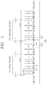
- FIG. 5 illustrates a permanent magnet electrical machine having seven permanent magnets and six mover slots and driven by a three-phase power source, according to another preferred embodiment of the present invention.
- FIG. 6 illustrates a permanent magnet electrical machine source having seven permanent magnets and nine mover slots and driven by a three-phase power, according to another preferred embodiment of the present invention.
- FIG. 7 illustrates a permanent magnet electrical machine having eight permanent magnets and nine mover slots and driven by a three-phase power source, according to another preferred embodiment of the present invention.
- FIG. 8 illustrates a permanent magnet electrical machine having ten permanent magnets and nine mover slots and driven by a three-phase power source, according to another preferred embodiment of the present invention.
- FIG. 9 illustrates a permanent magnet electrical machine having eleven permanent magnets and twelve mover slots and driven by a three-phase power source, according to another preferred embodiment of the present invention.
- FIG. 10 illustrates a permanent magnet electrical machine having thirteen permanent magnets and twelve mover slots and driven by a three-phase power source, according to another preferred embodiment of the present invention.
- FIG. 11 illustrates a permanent magnet electrical machine having ten permanent magnets and twelve mover slots and driven by a three-phase power source, according to another preferred embodiment of the present invention.
- FIG. 12 is a diagram designed to change a double layer winding of FIG. 1 into a single layer winding.
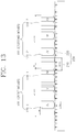
- FIG. 13 is a diagram designed to change a double layer winding of FIG. 5 into a single layer winding.
- FIG. 14 is a diagram designed to change a double layer winding of FIG. 9 into a single layer winding.
- FIG. 15 is a diagram designed to change a double layer winding of FIG. 10 into a single layer winding.
- FIG. 16 is a diagram designed to change a double layer winding of FIG. 11 into a single layer winding.
- FIG. 17 is a diagram illustrating comparison of detent force with respect to mover position between the permanent magnet electrical machine according to the prior art and the permanent magnet electrical machine according to the present invention.
- FIG. 18 is a diagram illustrating comparison of average thrust with respect to current rating between the permanent magnet electrical machine according to the prior art and the permanent magnet electrical machine according to the present invention.
- FIG. 19 illustrates a permanent magnet electrical machine having five permanent magnets and six mover slots and driven by a three-phase power source, in which movers of the permanent magnet electrical machine are continuously connected, to be compared with the present invention in FIGS. 17 and 18 .
- FIG. 20 is a simplified diagram of FIG. 19 .
- FIG. 1 illustrates a permanent magnet electrical machine having five permanent magnets and six mover slots and driven by a three-phase power source, according to a preferred embodiment of the present invention
- FIG. 2 is a simplified diagram of FIG. 1 .
- FIGS. 1 and 2 are diagrams for describing the overall structure of the permanent magnet electrical machine and the arrangement of a first mover 100 - 1 and a second mover 100 - 2 , which linearly move with respect to a stator 200 .
- first mover 100 - 1 and the second mover 100 - 2 are connected to form one iron core, the first mover 100 - 1 and the second mover 100 - 2 may be spaced from each other as illustrated in FIGS. 3 and 4 .
- the first mover 100 - 1 and the second mover 100 - 2 are disposed face to face with the stator 200 .
- a connecting portion between the first mover 100 - 1 and the second mover 100 - 2 extend by a weighted value (or weight) ⁇ .
- FIG. 3 illustrates a permanent magnet electrical machine having five permanent magnets and six mover slots and driven by a three-phase power source (or a three-phase power supply), according to a preferred embodiment of the present invention
- FIG. 4 is a simplified diagram of FIG. 3 .
- the first mover 100 - 1 and the second mover 100 - 2 are physically spaced apart from each other by a weighted value ⁇ .
- the permanent magnet electrical machine having five permanent magnets and six mover slots and driven by the three-phase power source includes a first mover 100 - 1 having first phase windings 120 - 1 on a first mover iron core 110 - 1 having teeth of a multiple of 3, a second mover 100 - 2 having second phase windings 120 - 2 on a second mover iron core 110 - 2 having teeth of a multiple of 3, and a stator 200 having permanent magnets 220 disposed on a straight stator iron core 210 having no teeth, wherein the permanent magnet 220 is arranged to have a magnetic polarity opposite to that of an adjacent permanent magnet.
- the arrangement of the permanent magnets has been described, it can be expressed as the arrangement of magnetic poles as the generic concept.
- the first phase windings 120 - 1 of the first mover 100 - 1 include U, /U, /V, V, W, and /W phases
- the second phase windings 120 - 2 of the second mover 100 - 2 include W, /W, /U, U, V, and /V phases.
- U and /U, V and /V, and W and /W have different current directions (i.e. have an electrical phase difference of 180°).
- U, V, and W of the phase windings 120 - 1 and 120 - 2 of the first mover 100 - 1 and the second mover 100 - 2 have an electrical phase difference of 120°.
- the lengths of the first mover 100 - 1 and the second mover 100 - 2 are L mover
- the number of poles is m
- the number of slots is s
- L mover m ⁇ p
- FIG. 5 illustrates a permanent magnet electrical machine having seven permanent magnets and six mover slots and driven by the three-phase power source, according to another preferred embodiment of the present invention, and is a diagram for describing the overall structure of the permanent magnet electrical machine and the arrangement of a first mover 100 - 1 and a second mover 100 - 2 which linearly move with respect to a stator 200 .
- the permanent magnet electrical machine having seven permanent magnets and six mover slots and driven by the three-phase power source includes a first mover 100 - 1 having first phase windings 120 - 1 on a first mover iron core 110 - 1 having teeth of a multiple of 3, a second mover 100 - 2 having second phase windings 120 - 2 on a second mover iron core 110 - 2 having teeth of a multiple of 3, and a stator 200 having permanent magnets 220 disposed on a straight stator iron core 210 having no stator teeth, wherein the permanent magnet 220 is arranged to have a magnetic polarity opposite to that of an adjacent permanent magnet.
- first mover 100 - 1 and the second mover 100 - 2 are connected to form one iron core, the first mover 100 - 1 and the second mover 100 - 2 may be spaced from each other.
- the first mover 100 - 1 and the second mover 100 - 2 are disposed face to face with the stator 200 .
- a connecting portion between the first mover 100 - 1 and the second mover 100 - 2 extend by a weighted value ⁇ .
- the first phase windings 120 - 1 of the first mover 100 - 1 include U, /U, /V, V, W, and /W phases
- the second phase windings 120 - 2 of the second mover 100 - 2 include V, /V, /W, W, U, and /U phases.
- U, V, and W of the phase windings 120 - 1 and 120 - 2 of the first mover 100 - 1 and the second mover 100 - 2 have an electrical phase difference of 120°.
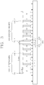
- FIG. 6 illustrates a permanent magnet electrical machine having seven permanent magnets and nine mover slots and driven by the three-phase power source, according to another preferred embodiment of the present invention, and is a diagram for describing the overall structure of the permanent magnet electrical machine and the arrangement of a first mover 100 - 1 and a second mover 100 - 2 which linearly move with respect to a stator 200 .
- the permanent magnet electrical machine having seven permanent magnets and nine mover slots and driven by the three-phase power source includes a first mover 100 - 1 having first phase windings 120 - 1 on a first mover iron core 110 - 1 having teeth of a multiple of 3, a second mover 100 - 2 having second phase windings 120 - 2 on a second mover iron core 110 - 2 having teeth of a multiple of 3, and a stator 200 having permanent magnets 220 disposed on a straight stator iron core 210 having no stator teeth, wherein the permanent magnet 220 is arranged to have a magnetic polarity opposite to that of an adjacent permanent magnet.
- first mover 100 - 1 and the second mover 100 - 2 are connected to form one iron core, the first mover 100 - 1 and the second mover 100 - 2 may be spaced from each other.
- a connecting portion between the first mover 100 - 1 and the second mover 100 - 2 extend by a weighted value ⁇ .
- the first mover 100 - 1 includes U, V, W, /W, /U, /V, V, W, and U phases
- the second mover 100 - 2 includes W, U, V, N, /W, /U, U, V, and W phases.
- U, V, and W of the phase windings 120 - 1 and 120 - 2 of the first mover 100 - 1 and the second mover 100 - 2 have an electrical phase difference of 120°.
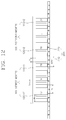
- FIG. 7 illustrates a permanent magnet electrical machine having eight permanent magnets and nine mover slots and driven by the three-phase power source, according to another preferred embodiment of the present invention, and is a diagram for describing the overall structure of the permanent magnet electrical machine and the arrangement of a first mover 100 - 1 and a second mover 100 - 2 which linearly move with respect to a stator 200 .
- the permanent magnet electrical machine having eight permanent magnets and nine mover slots and driven by the three-phase power source includes a first mover 100 - 1 having first phase windings 120 - 1 on a first mover iron core 110 - 1 having teeth of a multiple of 3, a second mover 100 - 2 having second phase windings 120 - 2 on a second mover iron core 110 - 2 having teeth of a multiple of 3, and a stator 200 having permanent magnets 220 disposed on a straight stator iron core 210 having no stator teeth, wherein the permanent magnet 220 is arranged to have a magnetic polarity opposite to that of an adjacent permanent magnet.
- first mover 100 - 1 and the second mover 100 - 2 are connected to form one iron core, the first mover 100 - 1 and the second mover 100 - 2 may be spaced from each other.
- a connecting portion between the first mover 100 - 1 and the second mover 100 - 2 extend by a weighted value ⁇ .
- the first mover 100 - 1 includes U, /U, U, V, /V, V, W, /W, and W phases
- the second mover 100 - 2 includes /W, W, /W, /U, U, /U, /V, V, and /V phases.
- U, V, and W of the phase windings 120 - 1 and 120 - 2 of the first mover 100 - 1 and the second mover 100 - 2 have an electrical phase difference of 120°.
- FIG. 8 illustrates a permanent magnet electrical machine having ten permanent magnets and nine mover slots and driven by the three-phase power source, according to another preferred embodiment of the present invention, and is a diagram for describing the overall structure of the permanent magnet electrical machine and the arrangement of a first mover 100 - 1 and a second mover 100 - 2 which linearly move with respect to a stator 200 .
- the permanent magnet electrical machine having ten permanent magnets and nine mover slots and driven by the three-phase power source includes a first mover 100 - 1 having first phase windings 120 - 1 on a first mover iron core 110 - 1 having teeth of a multiple of 3, a second mover 100 - 2 having second phase windings 120 - 2 on a second mover iron core 110 - 2 having teeth of a multiple of 3, and a stator 200 having permanent magnets 220 disposed on a straight stator iron core 210 having no stator teeth, wherein the permanent magnet 220 is arranged to have a magnetic polarity opposite to that of an adjacent permanent magnet.
- first mover 100 - 1 and the second mover 100 - 2 are connected to form one iron core, the first mover 100 - 1 and the second mover 100 - 2 may be spaced from each other.
- a connecting portion between the first mover 100 - 1 and the second mover 100 - 2 extend by a weighted value ⁇ .
- the first mover 100 - 1 includes U, /U, U, V, /V, V, W, /W, and W phases
- the second mover 100 - 2 includes /V, V, /V, /W, W, /W, /U, U, and /U phases.
- U, V, and W of the phase windings 120 - 1 and 120 - 2 of the first mover 100 - 1 and the second mover 100 - 2 have an electrical phase difference of 120°.
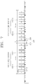
- FIG. 9 illustrates a permanent magnet electrical machine having eleven permanent magnets and twelve mover slots and driven by the three-phase power source, according to another preferred embodiment of the present invention, and is a diagram for describing the overall structure of the permanent magnet electrical machine and the arrangement of a first mover 100 - 1 and a second mover 100 - 2 which linearly move with respect to a stator 200 .
- the permanent magnet electrical machine having eleven permanent magnets and twelve mover slots and driven by the three-phase power source includes a first mover 100 - 1 having first phase windings 120 - 1 on a first mover iron core 110 - 1 having teeth of a multiple of 3, a second mover 100 - 2 having second phase windings 120 - 2 on a second mover iron core 110 - 2 having teeth of a multiple of 3, and a stator 200 having permanent magnets 220 disposed on a straight stator iron core 210 having no stator teeth, wherein the permanent magnet 220 is arranged to have a magnetic polarity opposite to that of an adjacent permanent magnet.
- first mover 100 - 1 and the second mover 100 - 2 are connected to form one iron core, the first mover 100 - 1 and the second mover 100 - 2 may be spaced from each other.
- a connecting portion between the first mover 100 - 1 and the second mover 100 - 2 extend by a weighted value ⁇ .
- the first mover 100 - 1 includes U, /U, U, /U, /V, V, /V, V, W, /W, W, and /W phases
- the second mover 100 - 2 includes W, /W, W, /W, /U, U, /U, U, V, /V, V, and /V phases.
- U, V, and W of the phase windings 120 - 1 and 120 - 2 of the first mover 100 - 1 and the second mover 100 - 2 have an electrical phase difference of 120°.
- FIG. 10 illustrates a permanent magnet electrical machine having thirteen permanent magnets and twelve mover slots and driven by the three-phase power source, according to another preferred embodiment of the present invention, and is a diagram for describing the overall structure of the permanent magnet electrical machine and the arrangement of a first mover 100 - 1 and a second mover 100 - 2 which linearly move with respect to a stator 200 .
- the permanent magnet electrical machine having thirteen permanent magnets and twelve mover slots and driven by the three-phase power source includes a first mover 100 - 1 having first phase windings 120 - 1 on a first mover iron core 110 - 1 having teeth of a multiple of 3, a second mover 100 - 2 having second phase windings 120 - 2 on a second mover iron core 110 - 2 having teeth of a multiple of 3, and a stator 200 having permanent magnets 220 disposed on a straight stator iron core 210 having no stator teeth, wherein the permanent magnet 220 is arranged to have a magnetic polarity opposite to that of an adjacent permanent magnet.
- first mover 100 - 1 and the second mover 100 - 2 are connected to form one iron core, the first mover 100 - 1 and the second mover 100 - 2 may be spaced from each other.
- a connecting portion between the first mover 100 - 1 and the second mover 100 - 2 extend by a weighted value ⁇ .
- the first mover 100 - 1 includes U, /U, U, /U, /V, V, /V, V, W, /W, W, and /W phases
- the second mover 100 - 2 includes V, /V, V, /V, /W, W, /W, W, U, /U, U, and /U phases.
- U, V, and W of the phase windings 120 - 1 and 120 - 2 of the first mover 100 - 1 and the second mover 100 - 2 have an electrical phase difference of 120°.
- FIG. 11 illustrates a permanent magnet electrical machine having ten permanent magnets and twelve mover slots and driven by the three-phase power source, according to another preferred embodiment of the present invention, and is a diagram for describing the overall structure of the permanent magnet electrical machine and the arrangement of a first mover 100 - 1 and a second mover 100 - 2 which linearly move with respect to a stator 200 .
- the permanent magnet electrical machine having ten permanent magnets and twelve mover slots and driven by the three-phase power source includes a first mover 100 - 1 having first phase windings 120 - 1 on a first mover iron core 110 - 1 having teeth of a multiple of 3, a second mover 100 - 2 having second phase windings 120 - 2 on a second mover iron core 110 - 2 having teeth of a multiple of 3, and a stator 200 having permanent magnets 220 disposed on a straight stator iron core 210 having no stator teeth, wherein the permanent magnet 220 is arranged to have a magnetic polarity opposite to that of an adjacent permanent magnet.
- first mover 100 - 1 and the second mover 100 - 2 are connected to form one iron core, the first mover 100 - 1 and the second mover 100 - 2 may be spaced from each other.
- a connecting portion between the first mover 100 - 1 and the second mover 100 - 2 extend by a weighted value ⁇ .
- the first mover 100 - 1 includes U, /U, N, V, W, /W, /U, U, V, /V, /W, and W phases
- the second mover 100 - 2 includes /W, W, U, /U, /V, V, W, /W, /U, U, V, and /V phases.
- U, V, and W of the phase windings 120 - 1 and 120 - 2 of the first mover 100 - 1 and the second mover 100 - 2 have an electrical phase difference of 120°.
- FIGS. 12 to 16 are diagrams illustrating that the embodiments of FIGS. 1 to 11 can be used not only in a double layer winding but also in a single layer winding.
- FIG. 12 is a diagram designed to change the double layer winding of FIG. 1 into a single layer winding.
- the number of the permanent magnets and the number of the mover slots are the same as those in FIG. 1 .
- the number of first phase windings 120 - 1 ′ provided in the first mover iron core 110 - 1 is 1 ⁇ 2 of the number of the first phase windings 120 - 1 in FIG. 1 .
- the number of second phase windings 120 - 2 ′ provided in the second mover iron core 110 - 2 is 1 ⁇ 2 of the number of the second phase windings 120 - 2 in FIG. 1 .
- the first phase windings 120 - 1 ′ of the first mover 100 - 1 are /U, V, and /W phases in sequence
- the second phase windings 120 - 2 ′ of the second mover 100 - 2 are /W, U, and /V phases in sequence
- the second phase windings 120 - 2 ′ of the second mover 100 - 2 may include W, /U, and V phases in sequence.
- FIG. 13 is a diagram designed to change the double layer winding of FIG. 5 into a single layer winding.
- the number of the permanent magnets and the number of the mover slots are the same as those in FIG. 5 .
- the number of first phase windings 120 - 1 ′ provided in the first mover iron core 110 - 1 is 1 ⁇ 2 of the number of the first phase windings 120 - 1 in FIG. 5 .
- the number of second phase windings 120 - 2 ′ provided in the second mover iron core 110 - 2 is 1 ⁇ 2 of the number of the second phase windings 120 - 2 in FIG. 5 .
- the first phase windings 120 - 1 ′ of the first mover 100 - 1 are /U, V, and /W phases
- the second phase windings 120 - 2 ′ of the second mover 100 - 2 are /V, W, and /U phases
- the second phase windings 120 - 2 ′ of the second mover 100 - 2 may include V, /W, and U phases.
- FIG. 14 is a diagram designed to change the double layer winding of FIG. 9 into a single layer winding.
- the number of the permanent magnets and the number of the mover slots are the same as those in FIG. 9 .
- the number of first phase windings 120 - 1 ′ provided in the first mover iron core 110 - 1 is 1 ⁇ 2 of the number of the first phase windings 120 - 1 in FIG. 9 .
- the number of second phase windings 120 - 2 ′ provided in the second mover iron core 110 - 2 is 1 ⁇ 2 of the number of the second phase windings 120 - 2 in FIG. 9 .
- the first mover 100 - 1 includes /U, /U, V, V, /W, and /W phases
- the second mover 100 - 2 includes /W, /W, U, U, /V, and /V phases.
- the second phase windings 120 - 2 ′ of the second mover 100 - 2 may include W, W, /U, /U, V, and V phases.
- FIG. 15 is a diagram designed to change the double layer winding of FIG. 10 into a single layer winding.
- the number of the permanent magnets and the number of the mover slots are the same as those in FIG. 10 .
- the number of first phase windings 120 - 1 ′ provided in the first mover iron core 110 - 1 is 1 ⁇ 2 of the number of the first phase windings 120 - 1 in FIG. 10 .
- the number of second phase windings 120 - 2 ′ provided in the second mover iron core 110 - 2 is 1 ⁇ 2 of the number of the second phase windings 120 - 2 in FIG. 10 .
- the first mover 100 - 1 includes /U, /U, V, V, /W, and /W phases
- the second mover 100 - 2 includes /V, /V, W, W, /U, and /U phases.
- the second phase windings 120 - 2 ′ of the second mover 100 - 2 may include V, V, /W, /W, U, and U phases.
- FIG. 16 is a diagram designed to change the double layer winding of FIG. 11 into a single layer winding.
- the number of the permanent magnets and the number of the mover slots are the same as those in FIG. 11 .
- the number of first phase windings 120 - 1 ′ provided in the first mover iron core 110 - 1 is 1 ⁇ 2 of the number of the first phase windings 120 - 1 in FIG. 11 .
- the number of second phase windings 120 - 2 ′ provided in the second mover iron core 110 - 2 is 1 ⁇ 2 of the number of the second phase windings 120 - 2 in FIG. 11 .
- the first mover 100 - 1 includes /U, V, /W, U, /V, and W phases
- the second mover 100 - 2 includes W, /U, V, /W, U, and /V phases.
- the second phase windings 120 - 2 ′ of the second mover 100 - 2 may include /W, U, /V, W, /U, and V phases.
- FIG. 17 is a diagram illustrating comparison of detent force with respect to mover position between the permanent magnet electrical machine in which the movers are continuously connected and the permanent magnet electrical machine according to the present invention.
- the permanent magnet electrical machine according to the present invention can reduce the detent force up to 65%, as compared with the permanent magnet electrical machine in which the movers are continuously connected.
- FIG. 18 is a diagram illustrating comparison of average thrust with respect to current rating between the permanent magnet electrical machine in which the movers are continuously connected and the permanent magnet electrical machine according to the present invention.
- the present invention can reduce the detent force while obtaining the same thrust characteristics as those of the permanent magnet electrical machine in which the movers are continuously connected.
- the detent force consists of a cogging force generated in the slot (or tooth) of the mover and an end force generated at both ends of the mover.
- a period of the cogging force is determined by a combination of the number of slots and the number of poles, and the cogging force can be effectively reduced by applying the mover or stator skew.
- the end force is generated by the magnetic interaction between the tooth at the left and right ends of the mover and the permanent magnet, the period is the same as the interval of the magnetic poles.
- the mover separation structure proposed in the present invention uses the phase difference of the end force generated in each mover.
- the end effect of the mover has occurred only in the right and left teeth of the mover. If the mover having 10 poles and 12 slots is separated by two movers having a 5-pole 6-slot structure, a new end effect occurs therein due to the separation distance between the movers.
- the end force generated in the right and left teeth of the first mover is substantially the same as the end force generated in the right and left teeth of the second mover, and the phase difference therebetween is 180°.
- the shortest separation distance that implements this effect is the pole pitch( ⁇ p )/phase number (n) of the electrical machine, which is the weighted value ( ⁇ ) suggested by the present invention.
- it is applicable to an electrical machine having an arbitrary phase.
- the same effect can be obtained by an integral multiple of the separation distance ( ⁇ ).
- ⁇ the separation distance
- the separation distance can be an integral multiple of 36°.
- FIG. 19 illustrates a permanent magnet electrical machine having five permanent magnets and six mover slots and driven by a three-phase power source, in which movers are continuously connected, to be compared with the present invention in FIGS. 17 and 18
- FIG. 20 is a simplified diagram of FIG. 19 .
- the permanent magnet electrical machine in which movers are continuously connected, to be compared with the present invention includes a first mover 100 - 1 having phase windings 12 - 1 having U, /U, /V, V, W, and W/ phases on a mover iron core 11 - 1 having teeth of a multiple of 3, a second mover 100 - 2 having phase windings 120 - 2 having /U, U, V, /V, /W, and W phases on a second mover iron core 11 - 2 having teeth of a multiple of 3, and a stator 20 having permanent magnets 22 disposed on a straight stator iron core 21 having no stator teeth and having permanent magnets 22 arranged to have a magnetic polarity opposite to that of an adjacent permanent magnet.
- the permanent magnet electrical machine to be compared with the present invention is based on, for example, the movers 10 - 1 and 10 - 2 having the 6-slot structure, and has the movers 10 - 1 and 10 - 2 continuously connected without being separated by a predetermined distance.
- the permanent magnet electrical machine has a 10-pole 12-slot structure.
- the pole pitch is ⁇ p
- the tooth arrangement interval ⁇ Is ⁇ 5 ⁇ p /6
- the phase arrangement of the first mover 10 - 1 is U, /U, /V, V, W, and /W
- the upper arrangement of the second mover 10 - 2 is /U, U, /V, V, /W, and W.
- U and /U, V and /V, and W and /W have opposite current directions.
- the permanent magnet electrical machine in which the movers are continuously connected, to be compared with the present invention has the same performance as the permanent magnet electrical machine having the 5-pole 6-slot structure of the present invention, but the pulsation of thrust occurs due to the end effect.
- the linear motion of the movers has been described as an example, but the present invention is not limited thereto. Therefore, the movers of permanent magnet electrical machine according to the present invention may be configured to perform curvilinear motion or rotary motion.
- a permanent magnet electrical machine according to the present invention can reduce a detent force up to 65%, as compared with a permanent magnet electrical machine in which movers are continuously connected.
- a permanent magnet electrical machine according to the present invention can reduce a detent force while maintaining the same thrust characteristics, as compared with a permanent magnet electrical machine in which movers are continuously connected.
Landscapes
- Engineering & Computer Science (AREA)
- Power Engineering (AREA)
- Physics & Mathematics (AREA)
- Chemical & Material Sciences (AREA)
- Combustion & Propulsion (AREA)
- Electromagnetism (AREA)
- Linear Motors (AREA)
- Permanent Magnet Type Synchronous Machine (AREA)
Abstract
Description
- (Patent Literature 1) Korean Patent Application Publication No. 10-2011-0120156
- (Patent Literature 2) Korean Patent Application Publication No. 10-2010-0113290
- (Patent Literature 3) Korean Patent Application Publication No. 10-2011-0001465
Claims (13)
Applications Claiming Priority (3)
| Application Number | Priority Date | Filing Date | Title |
|---|---|---|---|
| KR10-2016-0177567 | 2016-12-23 | ||
| KR20160177567 | 2016-12-23 | ||
| PCT/KR2017/015244 WO2018117690A1 (en) | 2016-12-23 | 2017-12-21 | Permanent magnet electrical machine for reducing detent force |
Publications (2)
| Publication Number | Publication Date |
|---|---|
| US20200212773A1 US20200212773A1 (en) | 2020-07-02 |
| US11139727B2 true US11139727B2 (en) | 2021-10-05 |
Family
ID=62627002
Family Applications (1)
| Application Number | Title | Priority Date | Filing Date |
|---|---|---|---|
| US16/349,574 Expired - Fee Related US11139727B2 (en) | 2016-12-23 | 2017-12-21 | Permanent magnet electrical machine for reducing detent force |
Country Status (4)
| Country | Link |
|---|---|
| US (1) | US11139727B2 (en) |
| KR (1) | KR102401588B1 (en) |
| CN (1) | CN109923775B (en) |
| WO (1) | WO2018117690A1 (en) |
Families Citing this family (5)
| Publication number | Priority date | Publication date | Assignee | Title |
|---|---|---|---|---|
| CN114598082A (en) * | 2022-03-05 | 2022-06-07 | 宁波恒帅股份有限公司 | A harmonic magnetic field drive motor |
| JP7833141B2 (en) * | 2022-03-23 | 2026-03-19 | カヤバ株式会社 | Cylindrical linear motor |
| CN115347755B (en) * | 2022-06-29 | 2026-01-09 | 中国科学院宁波材料技术与工程研究所 | Flat-plate type co-pole co-slot permanent magnet linear motor |
| CN116317443A (en) * | 2023-03-20 | 2023-06-23 | 成都恒感科技有限公司 | A four-phase four-pole linear reluctance motor |
| WO2024241363A1 (en) * | 2023-05-19 | 2024-11-28 | 三菱電機株式会社 | Stator and rotary electric machine provided with same |
Citations (22)
| Publication number | Priority date | Publication date | Assignee | Title |
|---|---|---|---|---|
| US4315171A (en) * | 1977-05-23 | 1982-02-09 | Ernest Schaeffer | Step motors |
| US4424463A (en) * | 1981-05-27 | 1984-01-03 | Musil J Donald | Apparatus for minimizing magnetic cogging in an electrical machine |
| US5642013A (en) * | 1994-11-16 | 1997-06-24 | Wavre; Nicolas | Permanent-magnet synchronous motor |
| WO2002023702A1 (en) | 2000-09-18 | 2002-03-21 | Kabushiki Kaisha Yaskawa Denki | Linear motor |
| US6407471B1 (en) * | 1998-05-12 | 2002-06-18 | Kabushiki Kaisha Yaskawa Denki | Linear motor |
| US6476524B1 (en) * | 1998-02-13 | 2002-11-05 | Kabushiki Kaisha Yaskawa Denki | Linear motor |
| US20060012252A1 (en) * | 2004-07-16 | 2006-01-19 | Shin-Etsu Chemical Co., Ltd. | Linear motor for use in machine tool |
| US20060125338A1 (en) | 2004-11-16 | 2006-06-15 | Ingolf Groening | Electrical induction machine and primary part |
| US7170202B2 (en) * | 2003-04-11 | 2007-01-30 | Mitsubishi Denki Kabushiki Kaisha | Linear motor |
| US7321176B2 (en) * | 2000-04-20 | 2008-01-22 | Invacare Corporation | Multi pole electrical machine with reduced cogging force |
| US20090322162A1 (en) | 2006-07-31 | 2009-12-31 | Siemens Aktiengesellschaft | Linear motor with force ripple compensation |
| KR20100113290A (en) | 2009-04-13 | 2010-10-21 | 한국전기연구원 | Linear and rotary electric machine structure |
| KR20110001465A (en) | 2009-06-30 | 2011-01-06 | 한국전기연구원 | Double-pole pole permanent magnet electric machine |
| CN101958633A (en) | 2010-09-26 | 2011-01-26 | 华中科技大学 | Composite core-based primary permanent magnet synchronous linear motor |
| KR20110120156A (en) | 2010-04-28 | 2011-11-03 | 한국전기연구원 | Winding arrangement method of double-pole pole permanent magnet electric machine |
| US8102085B2 (en) * | 2006-12-22 | 2012-01-24 | Siemens Aktiengesellschaft | Converter-fed single strand short stroke linear motor |
| CN102931803A (en) | 2012-10-10 | 2013-02-13 | 中国科学院宁波材料技术与工程研究所 | Permanent magnet synchronous linear motor for suppressing magnetic resistance |
| CN103227552A (en) | 2013-04-01 | 2013-07-31 | 南京航空航天大学 | Permanent magnet linear synchronous motor system with low thrust fluctuation and parameter design method of system |
| KR20130121291A (en) | 2012-04-27 | 2013-11-06 | 한국전기연구원 | Linear electric machine structure |
| US20140062223A1 (en) | 2012-09-03 | 2014-03-06 | Industry-Academic Cooperation Foundation, Yonsei University | Linear generator and method for generating power using the same |
| CN104410245A (en) | 2014-11-09 | 2015-03-11 | 沈阳工业大学 | Low-thrust fluctuation matrix combined iron core primary permanent magnet linear synchronous motor |
| CN106411096A (en) | 2016-10-31 | 2017-02-15 | 华中科技大学 | Modular vernier permanent magnetic linear motor based on Halbach permanent magnetic structure |
Family Cites Families (1)
| Publication number | Priority date | Publication date | Assignee | Title |
|---|---|---|---|---|
| JP2006034016A (en) * | 2004-07-16 | 2006-02-02 | Shin Etsu Chem Co Ltd | Linear motor for machine tools |
-
2017
- 2017-12-21 KR KR1020197005001A patent/KR102401588B1/en not_active Expired - Fee Related
- 2017-12-21 US US16/349,574 patent/US11139727B2/en not_active Expired - Fee Related
- 2017-12-21 CN CN201780065505.8A patent/CN109923775B/en not_active Expired - Fee Related
- 2017-12-21 WO PCT/KR2017/015244 patent/WO2018117690A1/en not_active Ceased
Patent Citations (23)
| Publication number | Priority date | Publication date | Assignee | Title |
|---|---|---|---|---|
| US4315171A (en) * | 1977-05-23 | 1982-02-09 | Ernest Schaeffer | Step motors |
| US4424463A (en) * | 1981-05-27 | 1984-01-03 | Musil J Donald | Apparatus for minimizing magnetic cogging in an electrical machine |
| US5642013A (en) * | 1994-11-16 | 1997-06-24 | Wavre; Nicolas | Permanent-magnet synchronous motor |
| US6476524B1 (en) * | 1998-02-13 | 2002-11-05 | Kabushiki Kaisha Yaskawa Denki | Linear motor |
| US6407471B1 (en) * | 1998-05-12 | 2002-06-18 | Kabushiki Kaisha Yaskawa Denki | Linear motor |
| US7321176B2 (en) * | 2000-04-20 | 2008-01-22 | Invacare Corporation | Multi pole electrical machine with reduced cogging force |
| WO2002023702A1 (en) | 2000-09-18 | 2002-03-21 | Kabushiki Kaisha Yaskawa Denki | Linear motor |
| US7170202B2 (en) * | 2003-04-11 | 2007-01-30 | Mitsubishi Denki Kabushiki Kaisha | Linear motor |
| US20060012252A1 (en) * | 2004-07-16 | 2006-01-19 | Shin-Etsu Chemical Co., Ltd. | Linear motor for use in machine tool |
| US20060125338A1 (en) | 2004-11-16 | 2006-06-15 | Ingolf Groening | Electrical induction machine and primary part |
| US20090322162A1 (en) | 2006-07-31 | 2009-12-31 | Siemens Aktiengesellschaft | Linear motor with force ripple compensation |
| US8102085B2 (en) * | 2006-12-22 | 2012-01-24 | Siemens Aktiengesellschaft | Converter-fed single strand short stroke linear motor |
| KR20100113290A (en) | 2009-04-13 | 2010-10-21 | 한국전기연구원 | Linear and rotary electric machine structure |
| KR20110001465A (en) | 2009-06-30 | 2011-01-06 | 한국전기연구원 | Double-pole pole permanent magnet electric machine |
| KR20110120156A (en) | 2010-04-28 | 2011-11-03 | 한국전기연구원 | Winding arrangement method of double-pole pole permanent magnet electric machine |
| US20130076159A1 (en) * | 2010-04-28 | 2013-03-28 | Korea Electrotechnology Research Institute | Winding configuration of doubly salient permanent magnet electric machine |
| CN101958633A (en) | 2010-09-26 | 2011-01-26 | 华中科技大学 | Composite core-based primary permanent magnet synchronous linear motor |
| KR20130121291A (en) | 2012-04-27 | 2013-11-06 | 한국전기연구원 | Linear electric machine structure |
| US20140062223A1 (en) | 2012-09-03 | 2014-03-06 | Industry-Academic Cooperation Foundation, Yonsei University | Linear generator and method for generating power using the same |
| CN102931803A (en) | 2012-10-10 | 2013-02-13 | 中国科学院宁波材料技术与工程研究所 | Permanent magnet synchronous linear motor for suppressing magnetic resistance |
| CN103227552A (en) | 2013-04-01 | 2013-07-31 | 南京航空航天大学 | Permanent magnet linear synchronous motor system with low thrust fluctuation and parameter design method of system |
| CN104410245A (en) | 2014-11-09 | 2015-03-11 | 沈阳工业大学 | Low-thrust fluctuation matrix combined iron core primary permanent magnet linear synchronous motor |
| CN106411096A (en) | 2016-10-31 | 2017-02-15 | 华中科技大学 | Modular vernier permanent magnetic linear motor based on Halbach permanent magnetic structure |
Non-Patent Citations (2)
| Title |
|---|
| International Search Report issued in related PCT application No. PCT/KR2017/015244 dated Mar. 30, 2018. |
| Notification of Second Office Action dated Jun. 30, 2021 issued in related Chinese Patent Application No. 201780065505.8. |
Also Published As
| Publication number | Publication date |
|---|---|
| WO2018117690A1 (en) | 2018-06-28 |
| US20200212773A1 (en) | 2020-07-02 |
| KR20190090371A (en) | 2019-08-01 |
| KR102401588B1 (en) | 2022-05-25 |
| CN109923775B (en) | 2021-11-30 |
| CN109923775A (en) | 2019-06-21 |
Similar Documents
| Publication | Publication Date | Title |
|---|---|---|
| US11139727B2 (en) | Permanent magnet electrical machine for reducing detent force | |
| US9692269B2 (en) | Winding configuration of doubly salient permanent magnet electric machine | |
| KR101092212B1 (en) | Double-pole pole permanent magnet electric machine | |
| JP5549567B2 (en) | Electric motor device | |
| RU2012116142A (en) | MULTI-PHASE STATOR DEVICE | |
| US9362789B2 (en) | Magnetic field-modulated transverse flux multiphase permanent magnet motor | |
| CN109149800B (en) | A 9n/10n-pole segmented rotor switched reluctance motor | |
| TWI678052B (en) | Rotary electric machine and direct drive electric motor | |
| US20130082549A1 (en) | Switched reluctance motor | |
| JP2004343903A (en) | Rotary linear synchronous motor | |
| TWI661664B (en) | motor | |
| WO2013023819A3 (en) | Electrical machine | |
| WO2020261809A1 (en) | Linear motor | |
| US8193673B2 (en) | Brush motor | |
| MX2011002583A (en) | Permanent magnet rotor and motor using the same. | |
| JP5734135B2 (en) | Electric machine and manufacturing method thereof | |
| JP5987789B2 (en) | Linear motor | |
| JP3824060B2 (en) | Linear motor | |
| TW201401733A (en) | Linear motor | |
| KR101338144B1 (en) | Linear Electric Machine Structure | |
| US20250125671A1 (en) | Stator and Electrical Machine | |
| JP2016019389A (en) | Rotary electric machine | |
| JP6610415B2 (en) | Three-phase synchronous machine and manufacturing method thereof | |
| KR20180043104A (en) | motor | |
| EP3261236B1 (en) | Linear motor |
Legal Events
| Date | Code | Title | Description |
|---|---|---|---|
| FEPP | Fee payment procedure |
Free format text: ENTITY STATUS SET TO UNDISCOUNTED (ORIGINAL EVENT CODE: BIG.); ENTITY STATUS OF PATENT OWNER: SMALL ENTITY |
|
| AS | Assignment |
Owner name: KOREA ELECTROTECHNOLOGY RESEARCH INSTITUTE, KOREA, REPUBLIC OF Free format text: ASSIGNMENT OF ASSIGNORS INTEREST;ASSIGNORS:CHUNG, SHI UK;KIM, JONG MOO;REEL/FRAME:049172/0564 Effective date: 20190502 |
|
| FEPP | Fee payment procedure |
Free format text: ENTITY STATUS SET TO SMALL (ORIGINAL EVENT CODE: SMAL); ENTITY STATUS OF PATENT OWNER: SMALL ENTITY |
|
| STPP | Information on status: patent application and granting procedure in general |
Free format text: FINAL REJECTION MAILED |
|
| STPP | Information on status: patent application and granting procedure in general |
Free format text: RESPONSE AFTER FINAL ACTION FORWARDED TO EXAMINER |
|
| STPP | Information on status: patent application and granting procedure in general |
Free format text: NOTICE OF ALLOWANCE MAILED -- APPLICATION RECEIVED IN OFFICE OF PUBLICATIONS |
|
| STPP | Information on status: patent application and granting procedure in general |
Free format text: AWAITING TC RESP, ISSUE FEE PAYMENT VERIFIED |
|
| STPP | Information on status: patent application and granting procedure in general |
Free format text: PUBLICATIONS -- ISSUE FEE PAYMENT VERIFIED |
|
| STCF | Information on status: patent grant |
Free format text: PATENTED CASE |
|
| FEPP | Fee payment procedure |
Free format text: MAINTENANCE FEE REMINDER MAILED (ORIGINAL EVENT CODE: REM.); ENTITY STATUS OF PATENT OWNER: SMALL ENTITY |
|
| LAPS | Lapse for failure to pay maintenance fees |
Free format text: PATENT EXPIRED FOR FAILURE TO PAY MAINTENANCE FEES (ORIGINAL EVENT CODE: EXP.); ENTITY STATUS OF PATENT OWNER: SMALL ENTITY |
|
| STCH | Information on status: patent discontinuation |
Free format text: PATENT EXPIRED DUE TO NONPAYMENT OF MAINTENANCE FEES UNDER 37 CFR 1.362 |
|
| FP | Lapsed due to failure to pay maintenance fee |
Effective date: 20251005 |