US11123776B2 - Methods and systems for landfill thermal insulation - Google Patents
Methods and systems for landfill thermal insulation Download PDFInfo
- Publication number
- US11123776B2 US11123776B2 US16/754,631 US201816754631A US11123776B2 US 11123776 B2 US11123776 B2 US 11123776B2 US 201816754631 A US201816754631 A US 201816754631A US 11123776 B2 US11123776 B2 US 11123776B2
- Authority
- US
- United States
- Prior art keywords
- layer
- foam glass
- glass aggregates
- waste
- aggregates
- Prior art date
- Legal status (The legal status is an assumption and is not a legal conclusion. Google has not performed a legal analysis and makes no representation as to the accuracy of the status listed.)
- Active
Links
Images


Classifications
-
- C—CHEMISTRY; METALLURGY
- C04—CEMENTS; CONCRETE; ARTIFICIAL STONE; CERAMICS; REFRACTORIES
- C04B—LIME, MAGNESIA; SLAG; CEMENTS; COMPOSITIONS THEREOF, e.g. MORTARS, CONCRETE OR LIKE BUILDING MATERIALS; ARTIFICIAL STONE; CERAMICS; REFRACTORIES; TREATMENT OF NATURAL STONE
- C04B14/00—Use of inorganic materials as fillers, e.g. pigments, for mortars, concrete or artificial stone; Treatment of inorganic materials specially adapted to enhance their filling properties in mortars, concrete or artificial stone
- C04B14/02—Granular materials, e.g. microballoons
- C04B14/04—Silica-rich materials; Silicates
- C04B14/22—Glass ; Devitrified glass
- C04B14/24—Glass ; Devitrified glass porous, e.g. foamed glass
-
- B—PERFORMING OPERATIONS; TRANSPORTING
- B09—DISPOSAL OF SOLID WASTE; RECLAMATION OF CONTAMINATED SOIL
- B09B—DISPOSAL OF SOLID WASTE NOT OTHERWISE PROVIDED FOR
- B09B1/00—Dumping solid waste
- B09B1/004—Covering of dumping sites
-
- B—PERFORMING OPERATIONS; TRANSPORTING
- B09—DISPOSAL OF SOLID WASTE; RECLAMATION OF CONTAMINATED SOIL
- B09B—DISPOSAL OF SOLID WASTE NOT OTHERWISE PROVIDED FOR
- B09B1/00—Dumping solid waste
-
- C—CHEMISTRY; METALLURGY
- C03—GLASS; MINERAL OR SLAG WOOL
- C03B—MANUFACTURE, SHAPING, OR SUPPLEMENTARY PROCESSES
- C03B19/00—Other methods of shaping glass
- C03B19/08—Other methods of shaping glass by foaming
-
- C—CHEMISTRY; METALLURGY
- C03—GLASS; MINERAL OR SLAG WOOL
- C03C—CHEMICAL COMPOSITION OF GLASSES, GLAZES OR VITREOUS ENAMELS; SURFACE TREATMENT OF GLASS; SURFACE TREATMENT OF FIBRES OR FILAMENTS MADE FROM GLASS, MINERALS OR SLAGS; JOINING GLASS TO GLASS OR OTHER MATERIALS
- C03C11/00—Multi-cellular glass ; Porous or hollow glass or glass particles
- C03C11/007—Foam glass, e.g. obtained by incorporating a blowing agent and heating
-
- B—PERFORMING OPERATIONS; TRANSPORTING
- B09—DISPOSAL OF SOLID WASTE; RECLAMATION OF CONTAMINATED SOIL
- B09B—DISPOSAL OF SOLID WASTE NOT OTHERWISE PROVIDED FOR
- B09B1/00—Dumping solid waste
- B09B1/006—Shafts or wells in waste dumps
-
- C—CHEMISTRY; METALLURGY
- C03—GLASS; MINERAL OR SLAG WOOL
- C03C—CHEMICAL COMPOSITION OF GLASSES, GLAZES OR VITREOUS ENAMELS; SURFACE TREATMENT OF GLASS; SURFACE TREATMENT OF FIBRES OR FILAMENTS MADE FROM GLASS, MINERALS OR SLAGS; JOINING GLASS TO GLASS OR OTHER MATERIALS
- C03C1/00—Ingredients generally applicable to manufacture of glasses, glazes, or vitreous enamels
- C03C1/002—Use of waste materials, e.g. slags
-
- C—CHEMISTRY; METALLURGY
- C04—CEMENTS; CONCRETE; ARTIFICIAL STONE; CERAMICS; REFRACTORIES
- C04B—LIME, MAGNESIA; SLAG; CEMENTS; COMPOSITIONS THEREOF, e.g. MORTARS, CONCRETE OR LIKE BUILDING MATERIALS; ARTIFICIAL STONE; CERAMICS; REFRACTORIES; TREATMENT OF NATURAL STONE
- C04B2111/00—Mortars, concrete or artificial stone or mixtures to prepare them, characterised by specific function, property or use
- C04B2111/00474—Uses not provided for elsewhere in C04B2111/00
- C04B2111/00767—Uses not provided for elsewhere in C04B2111/00 for waste stabilisation purposes
- C04B2111/00775—Uses not provided for elsewhere in C04B2111/00 for waste stabilisation purposes the composition being used as waste barriers or the like, e.g. compositions used for waste disposal purposes only, but not containing the waste itself
-
- E—FIXED CONSTRUCTIONS
- E02—HYDRAULIC ENGINEERING; FOUNDATIONS; SOIL SHIFTING
- E02D—FOUNDATIONS; EXCAVATIONS; EMBANKMENTS; UNDERGROUND OR UNDERWATER STRUCTURES
- E02D2300/00—Materials
- E02D2300/0004—Synthetics
-
- E—FIXED CONSTRUCTIONS
- E02—HYDRAULIC ENGINEERING; FOUNDATIONS; SOIL SHIFTING
- E02D—FOUNDATIONS; EXCAVATIONS; EMBANKMENTS; UNDERGROUND OR UNDERWATER STRUCTURES
- E02D2300/00—Materials
- E02D2300/0046—Foams
-
- E—FIXED CONSTRUCTIONS
- E02—HYDRAULIC ENGINEERING; FOUNDATIONS; SOIL SHIFTING
- E02D—FOUNDATIONS; EXCAVATIONS; EMBANKMENTS; UNDERGROUND OR UNDERWATER STRUCTURES
- E02D2300/00—Materials
- E02D2300/0079—Granulates
-
- E—FIXED CONSTRUCTIONS
- E02—HYDRAULIC ENGINEERING; FOUNDATIONS; SOIL SHIFTING
- E02D—FOUNDATIONS; EXCAVATIONS; EMBANKMENTS; UNDERGROUND OR UNDERWATER STRUCTURES
- E02D31/00—Protective arrangements for foundations or foundation structures; Ground foundation measures for protecting the soil or the subsoil water, e.g. preventing or counteracting oil pollution
- E02D31/002—Ground foundation measures for protecting the soil or subsoil water, e.g. preventing or counteracting oil pollution
- E02D31/006—Sealing of existing landfills, e.g. using mining techniques
-
- Y—GENERAL TAGGING OF NEW TECHNOLOGICAL DEVELOPMENTS; GENERAL TAGGING OF CROSS-SECTIONAL TECHNOLOGIES SPANNING OVER SEVERAL SECTIONS OF THE IPC; TECHNICAL SUBJECTS COVERED BY FORMER USPC CROSS-REFERENCE ART COLLECTIONS [XRACs] AND DIGESTS
- Y02—TECHNOLOGIES OR APPLICATIONS FOR MITIGATION OR ADAPTATION AGAINST CLIMATE CHANGE
- Y02W—CLIMATE CHANGE MITIGATION TECHNOLOGIES RELATED TO WASTEWATER TREATMENT OR WASTE MANAGEMENT
- Y02W30/00—Technologies for solid waste management
- Y02W30/30—Landfill technologies aiming to mitigate methane emissions
Definitions
- Waste landfill applications typically incorporate geosynthetic products (e.g., barrier layers, gas collection layers, etc.). However, heat produced by the biodegradation of the waste can have deleterious effects on these geosynthetic products.
- geosynthetic products e.g., barrier layers, gas collection layers, etc.
- Systems and methods are disclosed for landfill systems, comprising waste, a geosynthetic product, and a layer of foam glass aggregates interposed between the waste and the geosynthetic product.
- FIG. 1 depicts a landfill cap.
- FIG. 2 depicts a landfill cap comprising a layer of foam glass aggregates, such as lightweight-foamed glass aggregate (FG-LWA).
- foam glass aggregates such as lightweight-foamed glass aggregate (FG-LWA).
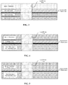
- FIG. 3 depicts a schematic of selected layers of a landfill cap incorporating FG-LWA.
- FIG. 4 depicts a schematic of selected layers of a landfill cap incorporating FG-LWA.
- FIG. 5 depicts a schematic of selected layers of a landfill cap incorporating FG-LWA.
- FIG. 6 depicts a landfill barrier liner thermally insulated from waste by a layer of FG-LWA.
- FIG. 1 depicts a landfill cap. Waste is covered by a soil barrier or cover layer.
- a geosynthetic product such as an impermeable plastic liner (e.g., reinforced polyethylene (e.g., high-density polyethylene (HDPE), linear low-density polyethylene (LLDPE) or other cover (e.g., reinforced polypropylene, thermoplastic olefin, ethylene propylene diene monomer, polyvinyl chloride, isobutylene isoprene, butyl rubber, etc.).
- the impermeable plastic liner acts to trap gas evolved from the biodegradation of the waste.
- a wellhead collects the landfill gas, which is transported from a collection pipe to a series of lateral pipes (not depicted).
- a layer of barrier protection material covers the impermeable plastic liner, for example, to prevent frost damage or mechanical puncture.
- Topsoil covers the barrier protection layer.
- FIG. 2 depicts a landfill cap having features as described with respect to FIG. 1 , but further comprising a layer of foam glass aggregates, such as lightweight-foamed glass aggregate (FG-LWA).
- a layer of FG-LAVA may be interposed between the soil barrier and the impermeable plastic liner.
- FG-LWA is an inert, stable, and environmentally friendly-substrate.
- recycled glass is cleaned, ground, mixed with a foaming agent, heated, and allowed to fragment from temperature shock.
- the resulting aggregate is cellular, with a relatively low bulk density, but relatively high durability.
- FG-LWA has many uses, for example, as a lightweight fill for construction applications, vehicle arrestor beds, building insulation, etc.
- FG-LWA provides an important economic driver for glass recycling, finding new uses and applications for FG-LWA is extremely desirable.
- FG-LWA is chemically inert.
- FG-LWA is extremely stable, it does not degrade, and is temperature stable to 800° C.
- a layer of FG-LWA may provide significant heat insulation for the impermeable plastic liner.
- the layer of FG-LWA may be from about six inches to about three feet thick.
- the layer of FG-LWA may be from about twelve inches to about twenty-four inches thick.
- Suitable FG-LWA may be procured from AERO AGGREGATES, LLC, Eddystone, Pa.
- the FG-LWA may be prepared from a recycled glass cullet.
- the FG-LWA may be prepared from a sodo-calic glass.
- FG-LWA is made up of silica, it may be considered a natural material for regulatory purposes.
- FG-LWA is made from recycled glass, it may be considered environmentally friendly.
- FG-LWA properties include low unit weight, low thermal conductivity, high strength, non-absorbent, non-toxic, non-leachable, chemically stable, impervious to UV degradation, freeze/thaw stable, and fireproof.
- the FG-LWA may be prepared from recycled glass cullet that contains less than 1% borosilicate glass.
- the FG-LWA may have a particle size of about 5 min to about 80 mm.
- the FG-LWA may have a particle size of about 10 mm to about 60 mm.
- the FG-LWA may have a bulk density of about 120 kg/m 3 to about 400 kg/m 3 .
- the FG-LWA may have a bulk density of about 200 kg/m 3 to about 240 kg/m 3 .
- the impermeable plastic liner may have a series of adjacent layers.
- a drainage layer may be interposed between the barrier protection layer and the impermeable plastic liner to provide drainage.
- a gas vent layer may be disposed under the impermeable plastic liner to facilitate gas collection.
- the heat insulating layer e.g., of FG-LWA
- the impermeable plastic liner may have a series of adjacent layers.
- a drainage layer may be interposed between the barrier protection layer and the impermeable plastic liner to provide drainage.
- a layer of FG-LWA may be disposed under (e.g., directly under) the impermeable plastic liner.
- the layer of FG-LWA may act as both a gas vent layer to facilitate gas collection and a heat insulating layer to protect the impermeable plastic liner and associated piping and components from excessive heat from the waste.
- FG-LWA may exhibit a high flow rate for gas collection.
- the impermeable plastic liner may have a series of adjacent layers.
- a first layer of FG-LWA may be placed above the impermeable plastic liner to provide drainage.
- FG-LWA is permeable to water, and does not compact, allowing water to pass through the layer of FG-LWA.
- a layer of FG-LWA may be used as a barrier protection layer in a landfill cap.
- FG-LWA exhibits exceptional long-term durability.
- FG-LWA is inert and does not degrade.
- FG-LWA has a low unit weight, thereby reducing settlement within the waste.
- FG-LWA provides frost protection. Accordingly, a barrier protection layer containing FG-LWA has the advantage of reducing the amount of topsoil required (e.g., as a cover layer) in colder regions (e.g., those with relatively deeper frost depth levels).
- a second layer of FG-LWA may be disposed under (e.g., directly under) the impermeable plastic liner.
- the second layer of FG-LWA may act as both a gas vent layer to facilitate gas collection and a heat insulating layer to protect the impermeable plastic liner and associated piping and components from excessive heat from the waste.
- a landfill may have a barrier liner (for example, to prevent leachate from reaching groundwater, for compliance with government regulation, etc.).
- a layer of FG-LWA may be placed above the barrier liner, interposed between the waste and the barrier liner.
- the FG-LWA may be used in conjunction with leachate lines (e.g., a leachate collection system), providing a lightweight, draining, fill.
- the FG-LWA may provide thermal insulation for the barrier liner from the waste.
- the layer of FG-LWA may be from about six inches to about twenty-four inches thick.
- the layer of FG-LWA may be about twelve inches thick.
- a landfill cap (depicted in dashed lines) may be placed above the waste.
- the landfill cap in one example, may be one described herein.
- Waste may be thermally insulated by two layers of FG-LWA, e.g., a layer of FG-LWA above the waste (e.g., thermally insulating the gas collection liner), and a layer of FG-LWA below the waste (e.g., thermally insulating the barrier liner).
- FG-LWA may also be combined with water treatment media (such as, for example steel slag, calcium carbonates, etc.) that removes phosphates and nitrates.
- water treatment media such as, for example steel slag, calcium carbonates, etc.
- Recycled glass cullet is cleaned, ground to less than 150 micrometers (US Standard sieve size No. 100), mixed with a foaming agent (e.g., a carbonate foaming agent) in a pug mill, heated, and allowed to fragment from temperature shock.
- a foaming agent e.g., a carbonate foaming agent
- the resulting FG-LWA is cellular.
- the initial moisture content is measured following ASTM D2216 (2010), grain size distributions are determined following ASTM C136/136M (2006) and the initial bulk density is measured following ASTM 0127 (2012a) on the FG-LWA.
- the average moisture content is determined to be 1.06% and the average bulk density is determined to be 227.2 kg/m3 (14.2 pcf).
- Sieve analyses are performed following the thy sieving method on the FG-LWA. Particle size ranges from 10 to 30 mm (0.39 to 1.18 in) but is a very uniformly graded material.
- Recycled glass cullet is cleaned, ground, mixed with a foaming agent, heated, and allowed to fragment from temperature shock.
- the resulting FG-LWA is cellular (foaming creates a thin wall of glass around each gas bubble). By volume, FG-LWA is approximately 92% gas bubbles and 8% glass.
- the water content (per ASTM D 2216) of FG-LWA is about 7%.
Landscapes
- Engineering & Computer Science (AREA)
- Chemical & Material Sciences (AREA)
- Environmental & Geological Engineering (AREA)
- Materials Engineering (AREA)
- Organic Chemistry (AREA)
- Life Sciences & Earth Sciences (AREA)
- Chemical Kinetics & Catalysis (AREA)
- Geochemistry & Mineralogy (AREA)
- General Chemical & Material Sciences (AREA)
- Ceramic Engineering (AREA)
- Civil Engineering (AREA)
- Structural Engineering (AREA)
- Manufacturing & Machinery (AREA)
- Processing Of Solid Wastes (AREA)
- Mining & Mineral Resources (AREA)
- Hydrology & Water Resources (AREA)
- General Life Sciences & Earth Sciences (AREA)
- Paleontology (AREA)
- General Engineering & Computer Science (AREA)
Abstract
Description
Claims (25)
Priority Applications (1)
| Application Number | Priority Date | Filing Date | Title |
|---|---|---|---|
| US16/754,631 US11123776B2 (en) | 2017-10-09 | 2018-10-09 | Methods and systems for landfill thermal insulation |
Applications Claiming Priority (3)
| Application Number | Priority Date | Filing Date | Title |
|---|---|---|---|
| US201762569739P | 2017-10-09 | 2017-10-09 | |
| US16/754,631 US11123776B2 (en) | 2017-10-09 | 2018-10-09 | Methods and systems for landfill thermal insulation |
| PCT/US2018/054969 WO2019074902A1 (en) | 2017-10-09 | 2018-10-09 | Methods and systems for landfill thermal insulation |
Related Parent Applications (1)
| Application Number | Title | Priority Date | Filing Date |
|---|---|---|---|
| PCT/US2018/054969 A-371-Of-International WO2019074902A1 (en) | 2017-10-09 | 2018-10-09 | Methods and systems for landfill thermal insulation |
Related Child Applications (1)
| Application Number | Title | Priority Date | Filing Date |
|---|---|---|---|
| US17/462,707 Continuation US11878331B2 (en) | 2017-10-09 | 2021-08-31 | Methods and systems for landfill thermal insulation |
Publications (2)
| Publication Number | Publication Date |
|---|---|
| US20200261951A1 US20200261951A1 (en) | 2020-08-20 |
| US11123776B2 true US11123776B2 (en) | 2021-09-21 |
Family
ID=66101027
Family Applications (2)
| Application Number | Title | Priority Date | Filing Date |
|---|---|---|---|
| US16/754,631 Active US11123776B2 (en) | 2017-10-09 | 2018-10-09 | Methods and systems for landfill thermal insulation |
| US17/462,707 Active US11878331B2 (en) | 2017-10-09 | 2021-08-31 | Methods and systems for landfill thermal insulation |
Family Applications After (1)
| Application Number | Title | Priority Date | Filing Date |
|---|---|---|---|
| US17/462,707 Active US11878331B2 (en) | 2017-10-09 | 2021-08-31 | Methods and systems for landfill thermal insulation |
Country Status (2)
| Country | Link |
|---|---|
| US (2) | US11123776B2 (en) |
| WO (1) | WO2019074902A1 (en) |
Cited By (2)
| Publication number | Priority date | Publication date | Assignee | Title |
|---|---|---|---|---|
| US20240017309A1 (en) * | 2022-07-14 | 2024-01-18 | Watershed Geosynthetics, LLC | Shallow well and conduit/collector grid |
| US11878331B2 (en) * | 2017-10-09 | 2024-01-23 | Aero Aggregates Of North America, Llc | Methods and systems for landfill thermal insulation |
Families Citing this family (2)
| Publication number | Priority date | Publication date | Assignee | Title |
|---|---|---|---|---|
| CN110528538B (en) * | 2019-08-30 | 2021-12-28 | 苏州市环境卫生管理处 | Refuse landfill and construction method thereof |
| US12234187B2 (en) | 2021-03-09 | 2025-02-25 | Bart Rockett | Lightweight structual concrete block and methods of use |
Citations (15)
| Publication number | Priority date | Publication date | Assignee | Title |
|---|---|---|---|---|
| US2691248A (en) | 1950-12-19 | 1954-10-12 | Pittsburgh Corning Corp | Nodulated cellular glass and method of forming |
| US4696599A (en) * | 1986-07-14 | 1987-09-29 | Waste Resource Associates, Inc. | Secure landfill and method of operating a landfill for hazardous waste |
| US5090843A (en) * | 1991-02-15 | 1992-02-25 | Grigsby Charles O | Chemical seal for waste disposal cover systems |
| US5447389A (en) * | 1993-01-15 | 1995-09-05 | Abeltech Incorporated | Insulation system for soil |
| US5516351A (en) | 1994-08-05 | 1996-05-14 | Recycled Glass Products, Inc. | Foamed glass manufacture |
| GB2294856A (en) | 1994-11-09 | 1996-05-15 | J G Tex Co Ltd | Underground drainage material for golf courses |
| US5857807A (en) * | 1996-06-14 | 1999-01-12 | R. J. Longo Construction Co., Inc. | Municipal solid waste landfill system |
| US20050126441A1 (en) * | 2003-12-01 | 2005-06-16 | Anthony David Skelhorn | Composition of a thermaly insulating coating system |
| US20060002764A1 (en) * | 2002-09-30 | 2006-01-05 | Legge Kelvin R | Geotechnical barrier |
| US20060029473A1 (en) | 2004-08-06 | 2006-02-09 | Board Of Trustees Of Michigan State University | Fluid distribution and collection in landfills and contaminated sites |
| US20090269140A1 (en) * | 2008-04-28 | 2009-10-29 | Waste Management, Inc. | Multi-Planar Gas Recovery Bioreactor |
| EP2363535A1 (en) | 2010-03-02 | 2011-09-07 | Exxag Investments Limited | Load bearing substructure of a structure or building |
| US20130272795A1 (en) * | 2011-10-05 | 2013-10-17 | Aquablok, Ltd. | Landfill including layer of composite particles |
| US20150136354A1 (en) * | 2011-07-25 | 2015-05-21 | Nazli Yesiller | Systems and methods for temperature control and heat extraction from waste landfills |
| US20160264446A1 (en) | 2015-03-13 | 2016-09-15 | Foamyna Canada Inc. | Foam glassy materials and processes for production |
Family Cites Families (3)
| Publication number | Priority date | Publication date | Assignee | Title |
|---|---|---|---|---|
| DE825695C (en) | 1949-12-07 | 1951-12-20 | Huettenwerk Rheinhausen A G | Method and device for pouring fiery liquid mass, e.g. Blast furnace slag |
| JP4067279B2 (en) * | 2001-02-01 | 2008-03-26 | 建設環境エンジニアリング有限会社 | Soil shielded water-filled disposal site |
| US11123776B2 (en) * | 2017-10-09 | 2021-09-21 | Aero Aggregates Of North America Llc | Methods and systems for landfill thermal insulation |
-
2018
- 2018-10-09 US US16/754,631 patent/US11123776B2/en active Active
- 2018-10-09 WO PCT/US2018/054969 patent/WO2019074902A1/en not_active Ceased
-
2021
- 2021-08-31 US US17/462,707 patent/US11878331B2/en active Active
Patent Citations (15)
| Publication number | Priority date | Publication date | Assignee | Title |
|---|---|---|---|---|
| US2691248A (en) | 1950-12-19 | 1954-10-12 | Pittsburgh Corning Corp | Nodulated cellular glass and method of forming |
| US4696599A (en) * | 1986-07-14 | 1987-09-29 | Waste Resource Associates, Inc. | Secure landfill and method of operating a landfill for hazardous waste |
| US5090843A (en) * | 1991-02-15 | 1992-02-25 | Grigsby Charles O | Chemical seal for waste disposal cover systems |
| US5447389A (en) * | 1993-01-15 | 1995-09-05 | Abeltech Incorporated | Insulation system for soil |
| US5516351A (en) | 1994-08-05 | 1996-05-14 | Recycled Glass Products, Inc. | Foamed glass manufacture |
| GB2294856A (en) | 1994-11-09 | 1996-05-15 | J G Tex Co Ltd | Underground drainage material for golf courses |
| US5857807A (en) * | 1996-06-14 | 1999-01-12 | R. J. Longo Construction Co., Inc. | Municipal solid waste landfill system |
| US20060002764A1 (en) * | 2002-09-30 | 2006-01-05 | Legge Kelvin R | Geotechnical barrier |
| US20050126441A1 (en) * | 2003-12-01 | 2005-06-16 | Anthony David Skelhorn | Composition of a thermaly insulating coating system |
| US20060029473A1 (en) | 2004-08-06 | 2006-02-09 | Board Of Trustees Of Michigan State University | Fluid distribution and collection in landfills and contaminated sites |
| US20090269140A1 (en) * | 2008-04-28 | 2009-10-29 | Waste Management, Inc. | Multi-Planar Gas Recovery Bioreactor |
| EP2363535A1 (en) | 2010-03-02 | 2011-09-07 | Exxag Investments Limited | Load bearing substructure of a structure or building |
| US20150136354A1 (en) * | 2011-07-25 | 2015-05-21 | Nazli Yesiller | Systems and methods for temperature control and heat extraction from waste landfills |
| US20130272795A1 (en) * | 2011-10-05 | 2013-10-17 | Aquablok, Ltd. | Landfill including layer of composite particles |
| US20160264446A1 (en) | 2015-03-13 | 2016-09-15 | Foamyna Canada Inc. | Foam glassy materials and processes for production |
Non-Patent Citations (4)
| Title |
|---|
| http://endeavourcentre.org/2012/08/a-remarkable-new-insulation/ (Year: 2012). * |
| Ozel, et al. "Utilization of Natural Zeolite and Perlite as Landfill Liners for in Situ Leachate Treatment in Landfills" Int. J. Environ. Res. Public Health 2012, 9, 1581-1592; doi:10.3390/ijerph9051581 (Year: 2012). * |
| Perlite Products for Every Application, preme Perlite in Portland, OR https://www.supremeperlite.com/products/ (Year: 2020). * |
| Physical Characteristics of Perlite, www.perlite.org (Year: 2020). * |
Cited By (3)
| Publication number | Priority date | Publication date | Assignee | Title |
|---|---|---|---|---|
| US11878331B2 (en) * | 2017-10-09 | 2024-01-23 | Aero Aggregates Of North America, Llc | Methods and systems for landfill thermal insulation |
| US20240017309A1 (en) * | 2022-07-14 | 2024-01-18 | Watershed Geosynthetics, LLC | Shallow well and conduit/collector grid |
| US12485464B2 (en) * | 2022-07-14 | 2025-12-02 | Watershed Geosynthetics Llc | Shallow well and conduit/collector grid |
Also Published As
| Publication number | Publication date |
|---|---|
| US20210394242A1 (en) | 2021-12-23 |
| WO2019074902A1 (en) | 2019-04-18 |
| US20200261951A1 (en) | 2020-08-20 |
| US11878331B2 (en) | 2024-01-23 |
Similar Documents
| Publication | Publication Date | Title |
|---|---|---|
| US11878331B2 (en) | Methods and systems for landfill thermal insulation | |
| US12110173B2 (en) | Lightweight-foamed glass aggregates for vaporization suppression | |
| CA2768109A1 (en) | Chemical resistant membrane | |
| WO2021146581A1 (en) | Foamed glass aggregate layer compaction | |
| EP3030723B1 (en) | Reactive treatment cell and systems for environmental remediation | |
| Reddy et al. | Review of the utilization of plastic wastes as a resource material in civil engineering infrastructure applications | |
| CN108976686A (en) | A kind of composite hydrogel, waterproof roll liner and preparation method thereof and its application | |
| EP1546470B1 (en) | Geotechnical barrier | |
| CN201817805U (en) | Closure structure of sludge house | |
| US20130272795A1 (en) | Landfill including layer of composite particles | |
| KR102573831B1 (en) | Firming agent for water impermeable barrier or blocking barrier of waste landfill | |
| KR102218731B1 (en) | Selective adsorption reactive smart liner with multi-layered structure | |
| CN205314137U (en) | A evaporation pond prevention of seepage protective screen system for coal industry strong brine | |
| EP3031986A1 (en) | Method of protection of ground waters | |
| CN113006157B (en) | Hazardous waste rigid landfill unit's system of closing a field | |
| US20220372720A1 (en) | Ultra-lightweight foamed glass aggregates for resiliency planning projects | |
| US8337381B2 (en) | Disposal process for residential solid waste | |
| KR101771136B1 (en) | Composition for protecting a stamping out livestock landfill, and method using the same | |
| KR100458266B1 (en) | System for flatting and waterproofing rugged slope in waste landfill using polyurethane foam | |
| KR102142823B1 (en) | Thermal insulation material having water-durability and Manufacturing method thereof | |
| JP3533019B2 (en) | Waterproof sheet | |
| Olatunji | Plastics in Construction: Toward Green Buildings and Climate-Resilient Cities | |
| JP4067279B2 (en) | Soil shielded water-filled disposal site | |
| KR101933566B1 (en) | Multilayered Sheet Having Radon Gas Barrier And Waterproofing Function | |
| Taskesti et al. | Impact of PFOS concentrations on the contaminating lifespan of landfills with a single composite liner |
Legal Events
| Date | Code | Title | Description |
|---|---|---|---|
| AS | Assignment |
Owner name: AEROAGGREGATES, LLC, PENNSYLVANIA Free format text: ASSIGNMENT OF ASSIGNORS INTEREST;ASSIGNORS:FILSHILL, ARCHIBALD STEWART;MCGRATH, THOMAS LIAM;REEL/FRAME:052346/0867 Effective date: 20190424 Owner name: AERO AGGREGATES OF NORTH AMERICA LLC, PENNSYLVANIA Free format text: ASSIGNMENT OF ASSIGNORS INTEREST;ASSIGNOR:AEROAGGREGATES, LLC;REEL/FRAME:052346/0941 Effective date: 20190401 |
|
| FEPP | Fee payment procedure |
Free format text: ENTITY STATUS SET TO UNDISCOUNTED (ORIGINAL EVENT CODE: BIG.); ENTITY STATUS OF PATENT OWNER: SMALL ENTITY |
|
| FEPP | Fee payment procedure |
Free format text: ENTITY STATUS SET TO SMALL (ORIGINAL EVENT CODE: SMAL); ENTITY STATUS OF PATENT OWNER: SMALL ENTITY |
|
| STPP | Information on status: patent application and granting procedure in general |
Free format text: NON FINAL ACTION MAILED |
|
| STPP | Information on status: patent application and granting procedure in general |
Free format text: RESPONSE TO NON-FINAL OFFICE ACTION ENTERED AND FORWARDED TO EXAMINER |
|
| STPP | Information on status: patent application and granting procedure in general |
Free format text: FINAL REJECTION MAILED |
|
| STPP | Information on status: patent application and granting procedure in general |
Free format text: RESPONSE AFTER FINAL ACTION FORWARDED TO EXAMINER |
|
| STPP | Information on status: patent application and granting procedure in general |
Free format text: NOTICE OF ALLOWANCE MAILED -- APPLICATION RECEIVED IN OFFICE OF PUBLICATIONS |
|
| STPP | Information on status: patent application and granting procedure in general |
Free format text: PUBLICATIONS -- ISSUE FEE PAYMENT RECEIVED |
|
| STPP | Information on status: patent application and granting procedure in general |
Free format text: PUBLICATIONS -- ISSUE FEE PAYMENT VERIFIED |
|
| STCF | Information on status: patent grant |
Free format text: PATENTED CASE |
|
| MAFP | Maintenance fee payment |
Free format text: PAYMENT OF MAINTENANCE FEE, 4TH YR, SMALL ENTITY (ORIGINAL EVENT CODE: M2551); ENTITY STATUS OF PATENT OWNER: SMALL ENTITY Year of fee payment: 4 |