US11118839B2 - Heat exchange assembly for heat exchanger, heat exchanger, and mold - Google Patents
Heat exchange assembly for heat exchanger, heat exchanger, and mold Download PDFInfo
- Publication number
- US11118839B2 US11118839B2 US16/333,740 US201716333740A US11118839B2 US 11118839 B2 US11118839 B2 US 11118839B2 US 201716333740 A US201716333740 A US 201716333740A US 11118839 B2 US11118839 B2 US 11118839B2
- Authority
- US
- United States
- Prior art keywords
- heat exchange
- exchange assembly
- assembly
- heat exchanger
- mold
- Prior art date
- Legal status (The legal status is an assumption and is not a legal conclusion. Google has not performed a legal analysis and makes no representation as to the accuracy of the status listed.)
- Active, expires
Links
Images


Classifications
-
- F—MECHANICAL ENGINEERING; LIGHTING; HEATING; WEAPONS; BLASTING
- F28—HEAT EXCHANGE IN GENERAL
- F28F—DETAILS OF HEAT-EXCHANGE AND HEAT-TRANSFER APPARATUS, OF GENERAL APPLICATION
- F28F1/00—Tubular elements; Assemblies of tubular elements
- F28F1/10—Tubular elements and assemblies thereof with means for increasing heat-transfer area, e.g. with fins, with projections, with recesses
- F28F1/12—Tubular elements and assemblies thereof with means for increasing heat-transfer area, e.g. with fins, with projections, with recesses the means being only outside the tubular element
- F28F1/24—Tubular elements and assemblies thereof with means for increasing heat-transfer area, e.g. with fins, with projections, with recesses the means being only outside the tubular element and extending transversely
- F28F1/32—Tubular elements and assemblies thereof with means for increasing heat-transfer area, e.g. with fins, with projections, with recesses the means being only outside the tubular element and extending transversely the means having portions engaging further tubular elements
-
- F—MECHANICAL ENGINEERING; LIGHTING; HEATING; WEAPONS; BLASTING
- F28—HEAT EXCHANGE IN GENERAL
- F28D—HEAT-EXCHANGE APPARATUS, NOT PROVIDED FOR IN ANOTHER SUBCLASS, IN WHICH THE HEAT-EXCHANGE MEDIA DO NOT COME INTO DIRECT CONTACT
- F28D1/00—Heat-exchange apparatus having stationary conduit assemblies for one heat-exchange medium only, the media being in contact with different sides of the conduit wall, in which the other heat-exchange medium is a large body of fluid, e.g. domestic or motor car radiators
- F28D1/02—Heat-exchange apparatus having stationary conduit assemblies for one heat-exchange medium only, the media being in contact with different sides of the conduit wall, in which the other heat-exchange medium is a large body of fluid, e.g. domestic or motor car radiators with heat-exchange conduits immersed in the body of fluid
- F28D1/03—Heat-exchange apparatus having stationary conduit assemblies for one heat-exchange medium only, the media being in contact with different sides of the conduit wall, in which the other heat-exchange medium is a large body of fluid, e.g. domestic or motor car radiators with heat-exchange conduits immersed in the body of fluid with plate-like or laminated conduits
- F28D1/0391—Heat-exchange apparatus having stationary conduit assemblies for one heat-exchange medium only, the media being in contact with different sides of the conduit wall, in which the other heat-exchange medium is a large body of fluid, e.g. domestic or motor car radiators with heat-exchange conduits immersed in the body of fluid with plate-like or laminated conduits a single plate being bent to form one or more conduits
-
- B—PERFORMING OPERATIONS; TRANSPORTING
- B21—MECHANICAL METAL-WORKING WITHOUT ESSENTIALLY REMOVING MATERIAL; PUNCHING METAL
- B21C—MANUFACTURE OF METAL SHEETS, WIRE, RODS, TUBES OR PROFILES, OTHERWISE THAN BY ROLLING; AUXILIARY OPERATIONS USED IN CONNECTION WITH METAL-WORKING WITHOUT ESSENTIALLY REMOVING MATERIAL
- B21C25/00—Profiling tools for metal extruding
- B21C25/02—Dies
-
- F—MECHANICAL ENGINEERING; LIGHTING; HEATING; WEAPONS; BLASTING
- F28—HEAT EXCHANGE IN GENERAL
- F28D—HEAT-EXCHANGE APPARATUS, NOT PROVIDED FOR IN ANOTHER SUBCLASS, IN WHICH THE HEAT-EXCHANGE MEDIA DO NOT COME INTO DIRECT CONTACT
- F28D1/00—Heat-exchange apparatus having stationary conduit assemblies for one heat-exchange medium only, the media being in contact with different sides of the conduit wall, in which the other heat-exchange medium is a large body of fluid, e.g. domestic or motor car radiators
- F28D1/02—Heat-exchange apparatus having stationary conduit assemblies for one heat-exchange medium only, the media being in contact with different sides of the conduit wall, in which the other heat-exchange medium is a large body of fluid, e.g. domestic or motor car radiators with heat-exchange conduits immersed in the body of fluid
- F28D1/04—Heat-exchange apparatus having stationary conduit assemblies for one heat-exchange medium only, the media being in contact with different sides of the conduit wall, in which the other heat-exchange medium is a large body of fluid, e.g. domestic or motor car radiators with heat-exchange conduits immersed in the body of fluid with tubular conduits
- F28D1/047—Heat-exchange apparatus having stationary conduit assemblies for one heat-exchange medium only, the media being in contact with different sides of the conduit wall, in which the other heat-exchange medium is a large body of fluid, e.g. domestic or motor car radiators with heat-exchange conduits immersed in the body of fluid with tubular conduits the conduits being bent, e.g. in a serpentine or zig-zag
- F28D1/0477—Heat-exchange apparatus having stationary conduit assemblies for one heat-exchange medium only, the media being in contact with different sides of the conduit wall, in which the other heat-exchange medium is a large body of fluid, e.g. domestic or motor car radiators with heat-exchange conduits immersed in the body of fluid with tubular conduits the conduits being bent, e.g. in a serpentine or zig-zag the conduits being bent in a serpentine or zig-zag
-
- F—MECHANICAL ENGINEERING; LIGHTING; HEATING; WEAPONS; BLASTING
- F28—HEAT EXCHANGE IN GENERAL
- F28D—HEAT-EXCHANGE APPARATUS, NOT PROVIDED FOR IN ANOTHER SUBCLASS, IN WHICH THE HEAT-EXCHANGE MEDIA DO NOT COME INTO DIRECT CONTACT
- F28D1/00—Heat-exchange apparatus having stationary conduit assemblies for one heat-exchange medium only, the media being in contact with different sides of the conduit wall, in which the other heat-exchange medium is a large body of fluid, e.g. domestic or motor car radiators
- F28D1/02—Heat-exchange apparatus having stationary conduit assemblies for one heat-exchange medium only, the media being in contact with different sides of the conduit wall, in which the other heat-exchange medium is a large body of fluid, e.g. domestic or motor car radiators with heat-exchange conduits immersed in the body of fluid
- F28D1/04—Heat-exchange apparatus having stationary conduit assemblies for one heat-exchange medium only, the media being in contact with different sides of the conduit wall, in which the other heat-exchange medium is a large body of fluid, e.g. domestic or motor car radiators with heat-exchange conduits immersed in the body of fluid with tubular conduits
- F28D1/053—Heat-exchange apparatus having stationary conduit assemblies for one heat-exchange medium only, the media being in contact with different sides of the conduit wall, in which the other heat-exchange medium is a large body of fluid, e.g. domestic or motor car radiators with heat-exchange conduits immersed in the body of fluid with tubular conduits the conduits being straight
- F28D1/05316—Assemblies of conduits connected to common headers, e.g. core type radiators
- F28D1/05333—Assemblies of conduits connected to common headers, e.g. core type radiators with multiple rows of conduits or with multi-channel conduits
-
- F—MECHANICAL ENGINEERING; LIGHTING; HEATING; WEAPONS; BLASTING
- F28—HEAT EXCHANGE IN GENERAL
- F28F—DETAILS OF HEAT-EXCHANGE AND HEAT-TRANSFER APPARATUS, OF GENERAL APPLICATION
- F28F1/00—Tubular elements; Assemblies of tubular elements
- F28F1/10—Tubular elements and assemblies thereof with means for increasing heat-transfer area, e.g. with fins, with projections, with recesses
- F28F1/12—Tubular elements and assemblies thereof with means for increasing heat-transfer area, e.g. with fins, with projections, with recesses the means being only outside the tubular element
- F28F1/14—Tubular elements and assemblies thereof with means for increasing heat-transfer area, e.g. with fins, with projections, with recesses the means being only outside the tubular element and extending longitudinally
- F28F1/16—Tubular elements and assemblies thereof with means for increasing heat-transfer area, e.g. with fins, with projections, with recesses the means being only outside the tubular element and extending longitudinally the means being integral with the element, e.g. formed by extrusion
-
- F—MECHANICAL ENGINEERING; LIGHTING; HEATING; WEAPONS; BLASTING
- F28—HEAT EXCHANGE IN GENERAL
- F28F—DETAILS OF HEAT-EXCHANGE AND HEAT-TRANSFER APPARATUS, OF GENERAL APPLICATION
- F28F1/00—Tubular elements; Assemblies of tubular elements
- F28F1/10—Tubular elements and assemblies thereof with means for increasing heat-transfer area, e.g. with fins, with projections, with recesses
- F28F1/12—Tubular elements and assemblies thereof with means for increasing heat-transfer area, e.g. with fins, with projections, with recesses the means being only outside the tubular element
- F28F1/14—Tubular elements and assemblies thereof with means for increasing heat-transfer area, e.g. with fins, with projections, with recesses the means being only outside the tubular element and extending longitudinally
- F28F1/20—Tubular elements and assemblies thereof with means for increasing heat-transfer area, e.g. with fins, with projections, with recesses the means being only outside the tubular element and extending longitudinally the means being attachable to the element
-
- F—MECHANICAL ENGINEERING; LIGHTING; HEATING; WEAPONS; BLASTING
- F28—HEAT EXCHANGE IN GENERAL
- F28F—DETAILS OF HEAT-EXCHANGE AND HEAT-TRANSFER APPARATUS, OF GENERAL APPLICATION
- F28F1/00—Tubular elements; Assemblies of tubular elements
- F28F1/10—Tubular elements and assemblies thereof with means for increasing heat-transfer area, e.g. with fins, with projections, with recesses
- F28F1/12—Tubular elements and assemblies thereof with means for increasing heat-transfer area, e.g. with fins, with projections, with recesses the means being only outside the tubular element
- F28F1/14—Tubular elements and assemblies thereof with means for increasing heat-transfer area, e.g. with fins, with projections, with recesses the means being only outside the tubular element and extending longitudinally
- F28F1/22—Tubular elements and assemblies thereof with means for increasing heat-transfer area, e.g. with fins, with projections, with recesses the means being only outside the tubular element and extending longitudinally the means having portions engaging further tubular elements
-
- F—MECHANICAL ENGINEERING; LIGHTING; HEATING; WEAPONS; BLASTING
- F28—HEAT EXCHANGE IN GENERAL
- F28F—DETAILS OF HEAT-EXCHANGE AND HEAT-TRANSFER APPARATUS, OF GENERAL APPLICATION
- F28F1/00—Tubular elements; Assemblies of tubular elements
- F28F1/10—Tubular elements and assemblies thereof with means for increasing heat-transfer area, e.g. with fins, with projections, with recesses
- F28F1/12—Tubular elements and assemblies thereof with means for increasing heat-transfer area, e.g. with fins, with projections, with recesses the means being only outside the tubular element
- F28F1/34—Tubular elements and assemblies thereof with means for increasing heat-transfer area, e.g. with fins, with projections, with recesses the means being only outside the tubular element and extending obliquely
-
- F—MECHANICAL ENGINEERING; LIGHTING; HEATING; WEAPONS; BLASTING
- F28—HEAT EXCHANGE IN GENERAL
- F28F—DETAILS OF HEAT-EXCHANGE AND HEAT-TRANSFER APPARATUS, OF GENERAL APPLICATION
- F28F9/00—Casings; Header boxes; Auxiliary supports for elements; Auxiliary members within casings
- F28F9/02—Header boxes; End plates
- F28F9/0243—Header boxes having a circular cross-section
-
- F—MECHANICAL ENGINEERING; LIGHTING; HEATING; WEAPONS; BLASTING
- F28—HEAT EXCHANGE IN GENERAL
- F28F—DETAILS OF HEAT-EXCHANGE AND HEAT-TRANSFER APPARATUS, OF GENERAL APPLICATION
- F28F9/00—Casings; Header boxes; Auxiliary supports for elements; Auxiliary members within casings
- F28F9/02—Header boxes; End plates
- F28F9/04—Arrangements for sealing elements into header boxes or end plates
- F28F9/16—Arrangements for sealing elements into header boxes or end plates by permanent joints, e.g. by rolling
-
- F—MECHANICAL ENGINEERING; LIGHTING; HEATING; WEAPONS; BLASTING
- F28—HEAT EXCHANGE IN GENERAL
- F28D—HEAT-EXCHANGE APPARATUS, NOT PROVIDED FOR IN ANOTHER SUBCLASS, IN WHICH THE HEAT-EXCHANGE MEDIA DO NOT COME INTO DIRECT CONTACT
- F28D1/00—Heat-exchange apparatus having stationary conduit assemblies for one heat-exchange medium only, the media being in contact with different sides of the conduit wall, in which the other heat-exchange medium is a large body of fluid, e.g. domestic or motor car radiators
- F28D1/02—Heat-exchange apparatus having stationary conduit assemblies for one heat-exchange medium only, the media being in contact with different sides of the conduit wall, in which the other heat-exchange medium is a large body of fluid, e.g. domestic or motor car radiators with heat-exchange conduits immersed in the body of fluid
- F28D1/04—Heat-exchange apparatus having stationary conduit assemblies for one heat-exchange medium only, the media being in contact with different sides of the conduit wall, in which the other heat-exchange medium is a large body of fluid, e.g. domestic or motor car radiators with heat-exchange conduits immersed in the body of fluid with tubular conduits
- F28D1/053—Heat-exchange apparatus having stationary conduit assemblies for one heat-exchange medium only, the media being in contact with different sides of the conduit wall, in which the other heat-exchange medium is a large body of fluid, e.g. domestic or motor car radiators with heat-exchange conduits immersed in the body of fluid with tubular conduits the conduits being straight
- F28D1/05316—Assemblies of conduits connected to common headers, e.g. core type radiators
- F28D1/05341—Assemblies of conduits connected to common headers, e.g. core type radiators with multiple rows of conduits or with multi-channel conduits combined with a particular flow pattern, e.g. multi-row multi-stage radiators
-
- F—MECHANICAL ENGINEERING; LIGHTING; HEATING; WEAPONS; BLASTING
- F28—HEAT EXCHANGE IN GENERAL
- F28F—DETAILS OF HEAT-EXCHANGE AND HEAT-TRANSFER APPARATUS, OF GENERAL APPLICATION
- F28F2215/00—Fins
- F28F2215/08—Fins with openings, e.g. louvers
-
- F—MECHANICAL ENGINEERING; LIGHTING; HEATING; WEAPONS; BLASTING
- F28—HEAT EXCHANGE IN GENERAL
- F28F—DETAILS OF HEAT-EXCHANGE AND HEAT-TRANSFER APPARATUS, OF GENERAL APPLICATION
- F28F2255/00—Heat exchanger elements made of materials having special features or resulting from particular manufacturing processes
- F28F2255/14—Heat exchanger elements made of materials having special features or resulting from particular manufacturing processes molded
-
- F—MECHANICAL ENGINEERING; LIGHTING; HEATING; WEAPONS; BLASTING
- F28—HEAT EXCHANGE IN GENERAL
- F28F—DETAILS OF HEAT-EXCHANGE AND HEAT-TRANSFER APPARATUS, OF GENERAL APPLICATION
- F28F2255/00—Heat exchanger elements made of materials having special features or resulting from particular manufacturing processes
- F28F2255/16—Heat exchanger elements made of materials having special features or resulting from particular manufacturing processes extruded
-
- F—MECHANICAL ENGINEERING; LIGHTING; HEATING; WEAPONS; BLASTING
- F28—HEAT EXCHANGE IN GENERAL
- F28F—DETAILS OF HEAT-EXCHANGE AND HEAT-TRANSFER APPARATUS, OF GENERAL APPLICATION
- F28F3/00—Plate-like or laminated elements; Assemblies of plate-like or laminated elements
- F28F3/02—Elements or assemblies thereof with means for increasing heat-transfer area, e.g. with fins, with recesses, with corrugations
- F28F3/04—Elements or assemblies thereof with means for increasing heat-transfer area, e.g. with fins, with recesses, with corrugations the means being integral with the element
- F28F3/042—Elements or assemblies thereof with means for increasing heat-transfer area, e.g. with fins, with recesses, with corrugations the means being integral with the element in the form of local deformations of the element
- F28F3/044—Elements or assemblies thereof with means for increasing heat-transfer area, e.g. with fins, with recesses, with corrugations the means being integral with the element in the form of local deformations of the element the deformations being pontual, e.g. dimples
-
- F—MECHANICAL ENGINEERING; LIGHTING; HEATING; WEAPONS; BLASTING
- F28—HEAT EXCHANGE IN GENERAL
- F28F—DETAILS OF HEAT-EXCHANGE AND HEAT-TRANSFER APPARATUS, OF GENERAL APPLICATION
- F28F9/00—Casings; Header boxes; Auxiliary supports for elements; Auxiliary members within casings
- F28F9/02—Header boxes; End plates
- F28F9/026—Header boxes; End plates with static flow control means, e.g. with means for uniformly distributing heat exchange media into conduits
- F28F9/0278—Header boxes; End plates with static flow control means, e.g. with means for uniformly distributing heat exchange media into conduits in the form of stacked distribution plates or perforated plates arranged over end plates
Definitions
- the embodiments of the present invention relate to a heat exchange assembly for a heat exchanger, a heat exchanger comprising the heat exchange assembly, and a mold for forming the heat exchange assembly.
- a heat exchanger generally comprises heat exchange tubes such as flat tubes, and corrugated fins disposed between the flat tubes.
- An object of the embodiments of the present invention is to provide a heat exchange assembly for a heat exchanger, a heat exchanger comprising the heat exchange assembly, and a mold for forming the heat exchange assembly, whereby, for example, product costs can be lowered.
- An embodiment of the present invention provides a heat exchange assembly for a heat exchanger, the heat exchange assembly comprising: multiple heat exchange tubes for a heat exchange medium to flow through; a connecting plate connected between adjacent heat exchange tubes; and a heat exchange plate formed by at least a part of the connecting plate.
- the connecting plate comprises a main body, and the heat exchange plate which is not in the same plane as the main body.
- the heat exchange plate comprises a louver-like heat exchange plate.
- the heat exchange plate comprises a main body, and a bridge plate protruding from the main body to one side of the main body in a direction perpendicular to the main body, with a part of a periphery of the bridge plate being separate from the main body.
- a length direction of the heat exchange plate is substantially perpendicular to, or forms an acute angle with, an axial direction of the heat exchange tube.
- the multiple heat exchange tubes and the connecting plate are formed as a single body by extrusion molding.
- a heat exchanger comprising the abovementioned heat exchange assembly for a heat exchanger.
- the heat exchanger further comprises a header, the heat exchange assembly being at least one layer of the heat exchange assembly substantially parallel to an axial direction of the header.
- the heat exchange assembly is a multiple-layer heat exchange assembly formed by bending a single heat exchange assembly.
- the multiple-layer heat exchange assembly is formed by bending a single heat exchange assembly in a direction substantially parallel or perpendicular to an axial direction of the heat exchange tube.
- the heat exchange assembly is a multiple-layer heat exchange assembly, and ends of multiple heat exchange tubes in the multiple-layer heat exchange assembly are respectively inserted into different openings of a header.
- the heat exchange assembly has the shape of a polygonal line when viewed in a direction parallel to an axial direction of the heat exchange tube.
- the heat exchange assembly has a corrugated shape when viewed in a direction perpendicular to an axial direction of the heat exchange tube.
- the heat exchange assembly is a multiple-layer heat exchange assembly, and heat exchange tubes of at least two layers of the heat exchange assembly in the heat exchange assembly are staggered with respect to each other in a direction perpendicular to an axial direction of the heat exchange tubes.
- the heat exchange assembly is a multiple-layer heat exchange assembly, and ends of multiple heat exchange tubes in the multiple-layer heat exchange assembly, which are arranged in a direction substantially perpendicular to or forming an acute angle with an axial direction of a header, are inserted into the same opening of the header.
- An embodiment of the present invention provides a mold for forming the abovementioned heat exchange assembly for a heat exchanger, the mold comprising: a first mold, being used to form holes of multiple heat exchange tubes; and a second mold, the second mold having a mold cavity for forming a main body of the heat exchange assembly, the mold cavity having an opening, and the heat exchange assembly being extruded from the opening of the mold cavity of the second mold,
- the curved line is a non-closed line.
- the curved line comprises at least one of the following: at least a part of a circumference, a spiral line and a polygonal line.
- a heat exchanger for a heat exchanger, a heat exchanger comprising the heat exchange assembly, and a mold for forming the heat exchange assembly according to embodiments of the present invention, for example, product costs can be lowered.
- FIG. 1 is a schematic three-dimensional view of a heat exchange assembly for a heat exchanger according to a first embodiment of the present invention
- FIG. 2 is a schematic three-dimensional view of a heat exchange assembly for a heat exchanger according to a second embodiment of the present invention
- FIG. 3 is a schematic side view of a heat exchange assembly for a heat exchanger according to a third embodiment of the present invention.
- FIG. 4 is a schematic three-dimensional view of the heat exchange assembly for a heat exchanger according to the third embodiment of the present invention.
- FIG. 5 is a schematic side view of a heat exchange assembly for a heat exchanger according to a fourth embodiment of the present invention.
- FIG. 6 is a schematic side view of a heat exchange assembly for a heat exchanger according to a fifth embodiment of the present invention.
- FIG. 7 is a schematic three-dimensional view of a heat exchange assembly for a heat exchanger according to a sixth embodiment of the present invention.
- FIG. 8 is a schematic three-dimensional view of a heat exchanger according to a first embodiment of the present invention.
- FIG. 9 is a schematic three-dimensional view of a heat exchanger according to a second embodiment of the present invention.
- FIG. 10 is a schematic three-dimensional view of one arrangement of a heat exchange assembly of a heat exchanger according to an embodiment of the present invention.
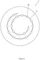
- FIG. 11 is a schematic three-dimensional view of another arrangement of a heat exchange assembly of a heat exchanger according to an embodiment of the present invention.
- FIG. 12 is a schematic three-dimensional view of a heat exchanger according to a third embodiment of the present invention.
- FIG. 13 is a schematic main view of a mold according to a first embodiment of the present invention.
- FIG. 14 is a schematic main view of a mold according to a second embodiment of the present invention.
- FIG. 15 is a schematic main view of a mold according to a third embodiment of the present invention.
- FIG. 16 is a schematic main view of a mold according to a fourth embodiment of the present invention.
- a heat exchange assembly 1 for a heat exchanger comprises: multiple heat exchange tubes 11 for a heat exchange medium to flow through; a connecting plate 12 connected between adjacent heat exchange tubes 11 ; and a heat exchange plate 121 formed by at least a part of the connecting plate 12 .
- the multiple heat exchange tubes 11 and the connecting plate 12 may be formed as a single body by extrusion molding or another method.
- the connecting plate 12 comprises a main body 120 , and a heat exchange plate 121 which is not in the same plane as the main body 120 .
- the heat exchange plate 121 comprises a louver-like heat exchange plate 121 .
- the ratio of a length of the heat exchange plate 121 to a width of the connecting plate 12 is in the range of 0.2-3.
- the heat exchange plate 121 comprises a main body 120 , and a bridge plate protruding from the main body 120 to one side of the main body 120 in a direction perpendicular to the main body 120 , with a part of a periphery of the bridge plate being separate from the main body 120 .
- a length direction of the heat exchange plate 121 may be substantially perpendicular to, or form an acute angle with, an axial direction of the heat exchange tube 11 .
- some drawings of heat exchangers and heat exchange assemblies 1 do not show louver-like heat exchange plates 121 and bridge plates, etc., the heat exchangers and heat exchange assemblies 1 shown in these drawings may be provided with heat exchange plates 121 and bridge plates, etc.
- the connecting plate 12 of the heat exchange assembly 1 undergoes window-opening and forms the louver-like heat exchange plate 121 , or the connecting plate 12 undergoes other processing, then multiple layers of the heat exchange assembly 1 are stacked to form multiple layers, or are folded to form multiple layers or form multiple layers in another manner, and two ends of the heat exchange tube are connected to two or more headers 15 .
- the heat exchange assembly 1 may be folded substantially in a length direction or a width direction.
- the connecting plate 12 of the heat exchange assembly 1 may be formed with slits, etc. Material may be removed from the connecting plate 12 .
- the shape of the removed material may be strip-like, block-like, round, etc.
- the heat exchange tube 11 may be round, square, rectangular or another shape. As shown in FIGS. 3 and 4 , both an inner side and an outer side of the heat exchange tube 11 may have fins or patterns. As shown in FIG. 5 , the heat exchange tube 11 may be a single-channel or a multi-channel heat exchange tube.
- the heat exchange assembly 1 may be bent or twisted in the axial direction of the heat exchange tube 11 or perpendicular to the axial direction of the heat exchange tube 11 , and may also be directly processed into a bent state.
- the heat exchange assembly 1 has the shape of a polygonal line when viewed in a direction parallel to the axial direction of the heat exchange tube 11 ; or the heat exchange assembly 1 has a corrugated shape when viewed in a direction perpendicular to the axial direction of the heat exchange tube.
- the heat exchange area of the heat exchange assembly 1 can thereby be increased.
- the sizes, numbers of through-holes and shapes etc. of the heat exchange tubes 11 of the heat exchange assembly 1 may be different, e.g. the diameters and cross-sectional shapes etc. of the heat exchange tubes 11 may be different.
- the sizes and shapes of the connecting plates 12 between the heat exchange tubes 11 may be different, e.g. the thicknesses and lengths etc. of the connecting plates 12 may be different.
- the structures etc. of window-openings on the connecting plates 12 (louver-like heat exchange plates) may be different, e.g. the lengths, angles and separations etc. of window-openings (louver-like heat exchange plates) may be different.
- the hydraulic diameter range of the heat exchange tube 11 may be 0.1-5 mm.
- the thickness range of the connecting plate 12 may be 0.02-1 mm, and the range of width (the distance between two adjacent heat exchange tubes 11 ) of the connecting plate 12 may be 3-30 mm.
- a heat exchanger according to an embodiment of the present invention is described below.
- a heat exchanger comprises a heat exchange assembly 1 .
- the heat exchanger further comprises a header 15 ; the heat exchange assembly 1 is at least one layer of the heat exchange assembly 1 which is substantially parallel to an axial direction of the header 15 , or a multiple-layer heat exchange assembly 1 ; each layer of the heat exchange assembly 1 in the multiple-layer heat exchange assembly 1 is substantially parallel to the axial direction of the header 15 .
- the multiple-layer heat exchange assembly 1 may be formed by bending a single heat exchange assembly 1 . As shown in FIGS. 10 and 11 , the multiple-layer heat exchange assembly 1 may be formed by bending a single heat exchange assembly in a direction substantially parallel or perpendicular to the axial direction of the heat exchange tube 11 .
- the heat exchange assembly 1 has the shape of a polygonal line when viewed in a direction parallel to the axial direction of the heat exchange tube 11 ; or the heat exchange assembly 1 has a corrugated shape when viewed in a direction perpendicular to the axial direction of the heat exchange tube.
- the heat exchange area of the heat exchange assembly 1 can thereby be increased.
- ends of multiple heat exchange tubes 11 in the multiple-layer heat exchange assembly 1 are respectively inserted into different openings of the header 15 .
- ends of multiple heat exchange tubes 11 in the multiple-layer heat exchange assembly 1 which are arranged in a direction substantially perpendicular to or forming an acute angle with the axial direction of the header 15 , are inserted into the same opening of the header 15 .
- ends of multiple heat exchange tubes 11 in the multiple-layer heat exchange assembly 1 which are located in the same position in the axial direction of the header 15 , are inserted into the same opening of the header 15 .
- a wind direction is substantially perpendicular to a plane in which the connecting plate 12 or the main body 120 of the connecting plate 12 lies.
- the heat exchanger may comprise a single-layer heat exchange assembly 1 or a multiple-layer heat exchange assembly 1 .
- the heat exchanger may be bent along the heat exchange tubes 11 , to form multiple bent parts.
- various independent heat exchange assemblies 1 may be stacked to form multiple layers.
- the heat exchange assemblies 1 in each of the layers may be stacked in an aligned manner. When the heat exchange assemblies 1 in each of the layers are placed perpendicularly, the axes of the corresponding heat exchange tubes 11 in each of the layers lie in the same horizontal plane.
- the various independent heat exchange assemblies 1 may be used in a stacked manner. Referring to FIG.
- the multiple-layer heat exchange assembly 1 may also be stacked in an alternating manner.
- heat exchange tubes 11 of at least two layers of the heat exchange assembly 1 in the heat exchange assembly 1 are staggered with respect to each other in a direction perpendicular to the axial direction of the heat exchange tubes 11 , in order to increase the contact of the heat exchange tubes 11 with air and promote air turbulence, thereby increasing the heat exchange efficiency of the heat exchanger.
- the heat exchange assemblies 1 in each of the layers are placed perpendicularly, the axes of the heat exchange tubes 11 in each of the layers lie in different horizontal planes.
- one independent heat exchange assembly 1 can be folded or bent into multiple layers for use.
- the heat exchange tubes 11 may be kept unchanged, and the lengths of each of the layers of heat exchange assembly 1 may be the same or different.
- the heat exchange assembly 1 may be bent along the heat exchange tubes 11 , to form multiple bent parts; multiple heat exchange tubes 11 at two ends of the heat exchange assembly 1 may be arranged substantially in the axial directions of the headers and inserted into the headers.
- the heat exchange tubes 11 on two adjacent layers of the heat exchange assembly 1 may be aligned or staggered.
- wind may blow in an up-down direction or a front-rear direction; the wind direction is substantially perpendicular or parallel to a plane in which the connecting plate 12 or the main body 120 of the connecting plate 12 lies.
- each layer of the heat exchange assembly 1 may have a different structure, and the distances between different layers of heat exchange assembly 1 , the numbers of heat exchange tubes on different layers of the heat exchange assembly 1 , the tube diameters, the dimensions of the connecting plates etc., and the window-openings on the connecting plates (louver-like heat exchange plates), etc. may all be different.
- the relationship between the distance (LD) between two adjacent layers of the heat exchange assembly 1 and the separation (LP) of window-openings on the connecting plates 12 (louver-like heat exchange plates) is: 0.2LP ⁇ LD ⁇ 10LP; the relationship between the distance (LD) between two adjacent layers of the heat exchange assembly 1 and the hydraulic diameter (HD) of the heat exchange tubes is: 0.2HD ⁇ LD ⁇ 10HD.
- two ends of the heat exchange tube may be connected to a single header or multiple headers. As shown in FIGS. 8 and 9 , each heat exchange tube may be inserted into the header individually, or as shown in FIG. 12 , multiple heat exchange tubes are placed together side by side, and then inserted into the header.
- a mold according to an embodiment of the present invention for forming a heat exchange assembly 1 is described below.
- the mold comprises: a first mold, being used to form holes 110 of multiple heat exchange tubes 11 (see FIGS. 1 and 2 ); and a second mold 2 , the second mold 2 having a mold cavity 20 for forming a main body of the heat exchange assembly 1 , the mold cavity 20 having an opening 21 , and the heat exchange assembly 1 being extruded from the opening 21 of the mold cavity 20 of the second mold 2 .
- the opening 21 is belt-like, and extends along a curved line.
- the curved line may be a non-closed line or a closed line.
- the curved line may comprise at least one of the following: at least a part of a circumference, a spiral line, a polygonal line and a zigzag line.
- the cross section of the extruded heat exchange assembly in a direction perpendicular to the axis of the heat exchange tube is non-linear, and may be in the shape of a non-closed curved line, e.g. a part of a circle, a spiral, or a part of a polygon, or zigzag-shaped.
- the extruded heat exchange assembly may form a linear shape by being opened out, etc. Using the method, a mold of small dimensions can also produce a product of large dimensions.
- the heat exchange assembly for a heat exchanger according to an embodiment of the present invention, and the heat exchanger comprising the heat exchange assembly, it is possible to increase the heat exchange efficiency, reduce product costs, increase the water drainage speed, extend the frost removal period, and reduce the refrigerant filling amount, and the product is easy to recycle.
- the heat exchange assembly may be arranged horizontally or vertically, and has a good water drainage effect in both cases.
Landscapes
- Engineering & Computer Science (AREA)
- Physics & Mathematics (AREA)
- Mechanical Engineering (AREA)
- Thermal Sciences (AREA)
- General Engineering & Computer Science (AREA)
- Geometry (AREA)
- Heat-Exchange Devices With Radiators And Conduit Assemblies (AREA)
- Moulds For Moulding Plastics Or The Like (AREA)
Abstract
Description
-
- wherein the opening is belt-like, and extends along a curved line.
Claims (18)
Applications Claiming Priority (3)
| Application Number | Priority Date | Filing Date | Title |
|---|---|---|---|
| CN201610859225.1A CN107869930B (en) | 2016-09-28 | 2016-09-28 | Heat exchange assembly for heat exchanger, heat exchanger and mold |
| CN201610859225.1 | 2016-09-28 | ||
| PCT/CN2017/103687 WO2018059443A1 (en) | 2016-09-28 | 2017-09-27 | Heat exchange assembly for heat exchanger, heat exchanger, and mold |
Publications (2)
| Publication Number | Publication Date |
|---|---|
| US20190360753A1 US20190360753A1 (en) | 2019-11-28 |
| US11118839B2 true US11118839B2 (en) | 2021-09-14 |
Family
ID=61761116
Family Applications (1)
| Application Number | Title | Priority Date | Filing Date |
|---|---|---|---|
| US16/333,740 Active 2037-12-27 US11118839B2 (en) | 2016-09-28 | 2017-09-27 | Heat exchange assembly for heat exchanger, heat exchanger, and mold |
Country Status (6)
| Country | Link |
|---|---|
| US (1) | US11118839B2 (en) |
| EP (1) | EP3521744B1 (en) |
| CN (1) | CN107869930B (en) |
| MX (1) | MX2019003477A (en) |
| PL (1) | PL3521744T3 (en) |
| WO (1) | WO2018059443A1 (en) |
Families Citing this family (11)
| Publication number | Priority date | Publication date | Assignee | Title |
|---|---|---|---|---|
| CN107869930B (en) * | 2016-09-28 | 2020-08-11 | 丹佛斯微通道换热器(嘉兴)有限公司 | Heat exchange assembly for heat exchanger, heat exchanger and mold |
| CN109900144B (en) * | 2017-12-08 | 2021-03-16 | 丹佛斯微通道换热器(嘉兴)有限公司 | Heat exchanger and heat exchange device with same |
| CN110345780A (en) * | 2018-04-03 | 2019-10-18 | 丹佛斯微通道换热器(嘉兴)有限公司 | Heat exchanger |
| CN108534395A (en) * | 2018-05-17 | 2018-09-14 | 广东美的制冷设备有限公司 | Heat exchanger and air conditioner with it |
| CN110186307A (en) * | 2019-06-27 | 2019-08-30 | 山东大学 | A kind of demisting, cooling integration heat exchanger tube and its device and application |
| DE202019104073U1 (en) * | 2019-07-23 | 2020-10-26 | Bundy Refrigeration Gmbh | Extruded wing tube section, wing tube with extruded wing tube section and heat exchanger with wing tube |
| CA3147666A1 (en) * | 2019-08-12 | 2021-02-18 | Enjay Ab | A battery device for a ventilation system |
| CN111829364A (en) * | 2019-10-08 | 2020-10-27 | 浙江三花智能控制股份有限公司 | Heat exchanger |
| US20220325956A1 (en) * | 2019-10-08 | 2022-10-13 | Hangzhou Sanhua Research Institute Co., Ltd. | Heat exchanger |
| CN111829363B (en) * | 2019-10-08 | 2022-07-22 | 浙江三花智能控制股份有限公司 | Heat exchanger |
| CN111220007B (en) * | 2019-11-29 | 2024-09-10 | 四川金象赛瑞化工股份有限公司 | Heat exchange plate, heat exchanger, application of heat exchange plate and washing cooling tower |
Citations (14)
| Publication number | Priority date | Publication date | Assignee | Title |
|---|---|---|---|---|
| EP0097905A2 (en) | 1982-06-24 | 1984-01-11 | COMPAGNIE GENERALE D'ELECTRICITE Société anonyme dite: | Water-air convector with chimney effect for space-heating, and method of producing such a convector |
| US5494099A (en) | 1994-05-16 | 1996-02-27 | Sanden Corporation | Heat exchanger |
| JPH10166034A (en) | 1996-12-11 | 1998-06-23 | Hitachi Cable Ltd | Manufacture of perforated flat tube |
| US20030070751A1 (en) | 2001-09-27 | 2003-04-17 | Kevin Bergevin | Method of manufacture for fluid handling polymeric barrier tube |
| US20040177948A1 (en) | 2003-03-13 | 2004-09-16 | Lg Electronics Inc. | Heat exchanger and fabrication method thereof |
| US20040261986A1 (en) * | 2003-06-27 | 2004-12-30 | Norsk Hydro A.S. | Method of forming heat exchanger tubing and tubing formed thereby |
| CN1981168A (en) | 2004-07-05 | 2007-06-13 | 昭和电工株式会社 | Evaporator |
| JP2007170718A (en) | 2005-12-20 | 2007-07-05 | Denso Corp | Heat exchanger |
| US20110036553A1 (en) * | 2009-08-12 | 2011-02-17 | Brian John Christen | Integral evaporator and defrost heater system |
| US20110180227A1 (en) | 2008-10-17 | 2011-07-28 | Brp Us Inc. | Method and apparatus for consumable-pattern casting |
| US20140034271A1 (en) * | 2012-08-01 | 2014-02-06 | Lg Electronics Inc. | Heat exchanger |
| CN104677162A (en) | 2013-11-29 | 2015-06-03 | 杭州三花微通道换热器有限公司 | Heat exchanger fin, heat exchanger and manufacturing method of heat exchanger fin |
| CN105371687A (en) | 2015-10-27 | 2016-03-02 | 珠海格力电器股份有限公司 | Heat exchange assembly, heat exchanger and refrigerating system |
| US20190360753A1 (en) * | 2016-09-28 | 2019-11-28 | Danfoss Micro Channel Heat Exchanger (Jiaxing) Co. | Heat exchange assembly for heat exchanger, heat exchanger, and mold |
Family Cites Families (2)
| Publication number | Priority date | Publication date | Assignee | Title |
|---|---|---|---|---|
| DE112005001373T5 (en) * | 2004-07-05 | 2007-06-14 | Showa Denko K.K. | Evaporator |
| ES2834434T3 (en) * | 2011-04-14 | 2021-06-17 | Carrier Corp | Heat exchanger |
-
2016
- 2016-09-28 CN CN201610859225.1A patent/CN107869930B/en active Active
-
2017
- 2017-09-27 US US16/333,740 patent/US11118839B2/en active Active
- 2017-09-27 EP EP17854893.9A patent/EP3521744B1/en active Active
- 2017-09-27 PL PL17854893.9T patent/PL3521744T3/en unknown
- 2017-09-27 MX MX2019003477A patent/MX2019003477A/en unknown
- 2017-09-27 WO PCT/CN2017/103687 patent/WO2018059443A1/en unknown
Patent Citations (15)
| Publication number | Priority date | Publication date | Assignee | Title |
|---|---|---|---|---|
| EP0097905A2 (en) | 1982-06-24 | 1984-01-11 | COMPAGNIE GENERALE D'ELECTRICITE Société anonyme dite: | Water-air convector with chimney effect for space-heating, and method of producing such a convector |
| US5494099A (en) | 1994-05-16 | 1996-02-27 | Sanden Corporation | Heat exchanger |
| JPH10166034A (en) | 1996-12-11 | 1998-06-23 | Hitachi Cable Ltd | Manufacture of perforated flat tube |
| US20030070751A1 (en) | 2001-09-27 | 2003-04-17 | Kevin Bergevin | Method of manufacture for fluid handling polymeric barrier tube |
| US20040177948A1 (en) | 2003-03-13 | 2004-09-16 | Lg Electronics Inc. | Heat exchanger and fabrication method thereof |
| US20040261986A1 (en) * | 2003-06-27 | 2004-12-30 | Norsk Hydro A.S. | Method of forming heat exchanger tubing and tubing formed thereby |
| CN1981168A (en) | 2004-07-05 | 2007-06-13 | 昭和电工株式会社 | Evaporator |
| JP2007170718A (en) | 2005-12-20 | 2007-07-05 | Denso Corp | Heat exchanger |
| US20110180227A1 (en) | 2008-10-17 | 2011-07-28 | Brp Us Inc. | Method and apparatus for consumable-pattern casting |
| US20110036553A1 (en) * | 2009-08-12 | 2011-02-17 | Brian John Christen | Integral evaporator and defrost heater system |
| US20140034271A1 (en) * | 2012-08-01 | 2014-02-06 | Lg Electronics Inc. | Heat exchanger |
| CN103574994A (en) | 2012-08-01 | 2014-02-12 | Lg电子株式会社 | Heat exchanger |
| CN104677162A (en) | 2013-11-29 | 2015-06-03 | 杭州三花微通道换热器有限公司 | Heat exchanger fin, heat exchanger and manufacturing method of heat exchanger fin |
| CN105371687A (en) | 2015-10-27 | 2016-03-02 | 珠海格力电器股份有限公司 | Heat exchange assembly, heat exchanger and refrigerating system |
| US20190360753A1 (en) * | 2016-09-28 | 2019-11-28 | Danfoss Micro Channel Heat Exchanger (Jiaxing) Co. | Heat exchange assembly for heat exchanger, heat exchanger, and mold |
Non-Patent Citations (2)
| Title |
|---|
| European Search Report for Serial No. EP 17854893.9 dated Mar. 30, 2020. |
| International Search Report for Serial No. PCT/CN2017/103687 dated Jan. 4, 2018. |
Also Published As
| Publication number | Publication date |
|---|---|
| WO2018059443A1 (en) | 2018-04-05 |
| MX2019003477A (en) | 2019-08-05 |
| CN107869930B (en) | 2020-08-11 |
| EP3521744A1 (en) | 2019-08-07 |
| US20190360753A1 (en) | 2019-11-28 |
| PL3521744T3 (en) | 2023-07-24 |
| CN107869930A (en) | 2018-04-03 |
| EP3521744A4 (en) | 2020-04-29 |
| EP3521744B1 (en) | 2023-04-05 |
Similar Documents
| Publication | Publication Date | Title |
|---|---|---|
| US11118839B2 (en) | Heat exchange assembly for heat exchanger, heat exchanger, and mold | |
| EP3399269B1 (en) | Double-row bent type heat exchanger and manufacturing method therefor | |
| US5722485A (en) | Louvered fin heat exchanger | |
| EP3141858B1 (en) | Bended heat exchanger | |
| US9080819B2 (en) | Folded heat exchanger with V-shaped convex portions | |
| EP3040667A1 (en) | Heat exchanger | |
| EP2985558B1 (en) | Fin-and-tube heat exchanger and refrigeration cycle device | |
| EP3040670A1 (en) | Heat exchanger, in particular a condenser or a gas cooler | |
| US10041740B2 (en) | Heat exchanger and production method therefor | |
| US11561014B2 (en) | Air conditioner including a heat exchanger | |
| WO2013001744A1 (en) | Fin tube heat exchanger | |
| KR20170087920A (en) | Multi port extrusion tubing design | |
| KR20170019340A (en) | Fins and bent heat exchanger with same | |
| JP2010038477A (en) | Porous tube for heat exchange | |
| US20100193172A1 (en) | Fin for a heat exchanger | |
| CN101782347B (en) | Heat exchanger and fin thereof | |
| CN110017703B (en) | Heat exchanger | |
| JP2002318086A (en) | Heat exchanger tube | |
| CN109900144A (en) | Heat exchanger and heat-exchanger rig with the heat exchanger | |
| KR20170074819A (en) | Sheet metal part with a rib structure of a heat exchanger having gills, as well as method of fabrication | |
| CN103273295B (en) | Heat exchanger and heat exchanger manufacturing method | |
| US20170153068A1 (en) | Heat exchanger core | |
| US20190195564A1 (en) | Heat exchanger | |
| KR20170022834A (en) | Heat exchanger with turbulence increasing features | |
| EP3009779B1 (en) | A tube of the gas cooler for the condenser |
Legal Events
| Date | Code | Title | Description |
|---|---|---|---|
| FEPP | Fee payment procedure |
Free format text: ENTITY STATUS SET TO UNDISCOUNTED (ORIGINAL EVENT CODE: BIG.); ENTITY STATUS OF PATENT OWNER: LARGE ENTITY |
|
| AS | Assignment |
Owner name: DANFOSS MICRO CHANNEL HEAT EXCHANGER (JIAXING) CO., LTD., CHINA Free format text: ASSIGNMENT OF ASSIGNORS INTEREST;ASSIGNORS:ZHANG, FENG;LU, XIANGXUN;PELLETIER, PIERRE OLIVIER;REEL/FRAME:050785/0697 Effective date: 20190214 Owner name: DANFOSS MICRO CHANNEL HEAT EXCHANGER (JIAXING) CO. Free format text: ASSIGNMENT OF ASSIGNORS INTEREST;ASSIGNORS:ZHANG, FENG;LU, XIANGXUN;PELLETIER, PIERRE OLIVIER;REEL/FRAME:050785/0697 Effective date: 20190214 |
|
| STPP | Information on status: patent application and granting procedure in general |
Free format text: DOCKETED NEW CASE - READY FOR EXAMINATION |
|
| STPP | Information on status: patent application and granting procedure in general |
Free format text: NON FINAL ACTION MAILED |
|
| STPP | Information on status: patent application and granting procedure in general |
Free format text: RESPONSE TO NON-FINAL OFFICE ACTION ENTERED AND FORWARDED TO EXAMINER |
|
| STPP | Information on status: patent application and granting procedure in general |
Free format text: NOTICE OF ALLOWANCE MAILED -- APPLICATION RECEIVED IN OFFICE OF PUBLICATIONS |
|
| STPP | Information on status: patent application and granting procedure in general |
Free format text: PUBLICATIONS -- ISSUE FEE PAYMENT VERIFIED |
|
| STCF | Information on status: patent grant |
Free format text: PATENTED CASE |