US11114236B2 - Band feeding process and system as well as plant for the production of laminated cores for transformers - Google Patents
Band feeding process and system as well as plant for the production of laminated cores for transformers Download PDFInfo
- Publication number
- US11114236B2 US11114236B2 US16/617,336 US201816617336A US11114236B2 US 11114236 B2 US11114236 B2 US 11114236B2 US 201816617336 A US201816617336 A US 201816617336A US 11114236 B2 US11114236 B2 US 11114236B2
- Authority
- US
- United States
- Prior art keywords
- feeding
- band
- input
- guide
- station
- Prior art date
- Legal status (The legal status is an assumption and is not a legal conclusion. Google has not performed a legal analysis and makes no representation as to the accuracy of the status listed.)
- Active
Links
- 238000000034 method Methods 0.000 title claims abstract description 27
- 238000004519 manufacturing process Methods 0.000 title claims abstract description 20
- 238000003475 lamination Methods 0.000 claims abstract description 24
- 229910000976 Electrical steel Inorganic materials 0.000 claims abstract description 9
- 230000005291 magnetic effect Effects 0.000 claims abstract description 9
- 230000005294 ferromagnetic effect Effects 0.000 claims abstract description 5
- 239000007769 metal material Substances 0.000 claims abstract description 5
- 238000005520 cutting process Methods 0.000 claims description 5
- 238000004804 winding Methods 0.000 claims 1
- 241000196324 Embryophyta Species 0.000 description 23
- 238000009826 distribution Methods 0.000 description 6
- 230000005540 biological transmission Effects 0.000 description 4
- 239000000463 material Substances 0.000 description 4
- 238000011144 upstream manufacturing Methods 0.000 description 4
- 230000008878 coupling Effects 0.000 description 2
- 238000010168 coupling process Methods 0.000 description 2
- 238000005859 coupling reaction Methods 0.000 description 2
- 239000002184 metal Substances 0.000 description 2
- 241000252254 Catostomidae Species 0.000 description 1
- XUIMIQQOPSSXEZ-UHFFFAOYSA-N Silicon Chemical compound [Si] XUIMIQQOPSSXEZ-UHFFFAOYSA-N 0.000 description 1
- 238000005452 bending Methods 0.000 description 1
- 230000015556 catabolic process Effects 0.000 description 1
- 238000006731 degradation reaction Methods 0.000 description 1
- 239000003302 ferromagnetic material Substances 0.000 description 1
- 238000009434 installation Methods 0.000 description 1
- 230000002452 interceptive effect Effects 0.000 description 1
- 229910052710 silicon Inorganic materials 0.000 description 1
- 239000010703 silicon Substances 0.000 description 1
Images


Classifications
-
- H—ELECTRICITY
- H01—ELECTRIC ELEMENTS
- H01F—MAGNETS; INDUCTANCES; TRANSFORMERS; SELECTION OF MATERIALS FOR THEIR MAGNETIC PROPERTIES
- H01F41/00—Apparatus or processes specially adapted for manufacturing or assembling magnets, inductances or transformers; Apparatus or processes specially adapted for manufacturing materials characterised by their magnetic properties
- H01F41/02—Apparatus or processes specially adapted for manufacturing or assembling magnets, inductances or transformers; Apparatus or processes specially adapted for manufacturing materials characterised by their magnetic properties for manufacturing cores, coils, or magnets
- H01F41/0206—Manufacturing of magnetic cores by mechanical means
- H01F41/0233—Manufacturing of magnetic circuits made from sheets
-
- H—ELECTRICITY
- H01—ELECTRIC ELEMENTS
- H01F—MAGNETS; INDUCTANCES; TRANSFORMERS; SELECTION OF MATERIALS FOR THEIR MAGNETIC PROPERTIES
- H01F41/00—Apparatus or processes specially adapted for manufacturing or assembling magnets, inductances or transformers; Apparatus or processes specially adapted for manufacturing materials characterised by their magnetic properties
- H01F41/02—Apparatus or processes specially adapted for manufacturing or assembling magnets, inductances or transformers; Apparatus or processes specially adapted for manufacturing materials characterised by their magnetic properties for manufacturing cores, coils, or magnets
- H01F41/0206—Manufacturing of magnetic cores by mechanical means
- H01F41/0213—Manufacturing of magnetic circuits made from strip(s) or ribbon(s)
Definitions
- This patent application relates to a band feeding process and system for a plant for the production of laminated cores for transformers, in particular for the production of cores with stacked grain-oriented laminations for electrical energy transmission and distribution transformers, namely for transformers with a power exceeding 10 kVA.
- This patent application further relates to a plant for the production of laminated cores for transformers, in particular for the production of cores with stacked grain-oriented laminations for electrical energy transmission and distribution transformers, namely for transformers with a power exceeding 10 kVA.
- Laminated cores of this type are large-sized and significantly heavy, thus requiring suitable production plants and manipulation instruments.
- laminated cores of the type described above usually comprise a lower joke, an upper joke and a plurality of columns, which transversely connect the lower joke and the upper joke to one another.
- the columns of the cores can have lengths ranging, for example, from 0.5 to 5 metres.
- these cores are manufactured through the combination and overlapping of a plurality of flat laminations, which are never subjected to bending.
- Known plants have a feeding station where a spool is unwound so as to feed, through an input, a band to a processing unit, in order to cut and separate the band.
- the spool is replaced.
- known plants comprise one single multi-spindle reel, wherein each spindle supports a respective spool. Therefore, the band exchange in a known plant basically comprises the following steps:
- This process is affected by the drawback of having to completely interrupt the production of the plant for a significant amount of time, ranging, based on the type of transformer to be manufactured, from 10% to 15% of the total production time.
- the object of the invention is to provide a feeding process and system, which allow the band to be exchanged in a few seconds.
- FIG. 1 is a schematic view of a core with stacked grain-oriented laminations for energy transmission and distribution transformers
- FIG. 2 is a plan view of a plant according to the invention.
- FIG. 3 is a plan view of a detail of FIG. 2 ;
- FIG. 4 is a side view of the detail of FIG. 3 ;
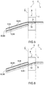
- FIG. 5 is a schematic view of a further detail of FIG. 1 in a first operating configuration
- FIG. 6 is similar to FIG. 5 and shows the further detail in a second operating configuration
- FIG. 7 is a prospective view of a second embodiment of the particular of FIGS. 3 and 4 ;
- FIG. 8 is a lateral view of FIG. 7 ;
- FIG. 9 is a section according to line IX-IX of FIG. 8 ;
- FIGS. 10 and 11 are schematic views of a particular of FIG. 8 in a first and in second, respectively, operating configuration
- FIG. 12 is a lateral view of a particular of FIG. 8 ;
- FIG. 13 is a plant view of FIG. 12 ;
- FIG. 14 is a section according to line XIV-XIV of FIG. 13 .
- FIG. 1 O indicates, as a whole, a laminated core, in particular for distribution or power transformers, namely for electrical energy transmission and distribution transformers, namely for transformers with a power exceeding 10 kVA.
- the core O comprises, in a known manner, a lower joke GI and an upper joke GS, which are transversely connected to one another by a plurality of columns C. According to the example shown, there are three columns, two side ones indicated with C 1 and C 3 and a central one indicated with C 2 .
- Each joke GI, GS and each column are manufactured by overlapping a plurality of laminations P made of magnetic silicon steel.
- Each joke GI, GS is connected to respective ends of the columns C 1 , C 2 and C 3 by means of a shape coupling, in particular by means of a herringbone coupling.
- At least part of the core O described above was manufactured by cutting and overlapping the laminations P starting from one single band B.
- the plant 1 comprises, in a known and schematically shown manner, a processing unit 2 , which has, in turn, one or more cutting stations ⁇ arranged in series, where the singles laminations P are cut and separated from one another starting from a ferromagnetic metal material band B, in particular made of magnetic silicon steel.
- the plant 1 further comprises a stacking unit 3 downstream of the processing unit 2 , where stacks of laminations P are obtained (in a known manner) in order to form the jokes GI, GS and the columns C 1 , C 2 and C 3 .
- the plant 1 further comprises a feeding system 4 , which is configured, as explained more in detail below, to feed a band B selected among a plurality of different bands, in particular having different widths, to the processing unit 2 in a basically instantaneous manner.
- This feeding system 4 find advantageous application especially when the band B in the processing unit 2 needs to be replaced.
- the processing unit 2 has an interface input I interfaced with the feeding system 4 , thus allowing bands B coming from the feeding system 4 to get into the processing station 2 .
- the feeding system 4 has a plurality of feeding stations ⁇ , each configured to feed a respective band B to the input I.
- upstream and downstream are used with reference to the feeding direction of a band B from the respective feeding station ⁇ towards the input I.
- the feeding system 4 is configured to selectively feed a plurality of continuous bands B 1 -B 8 , which are wound in spools 5 and are made of a ferromagnetic material, namely a material that is suited to be used to manufacture laminations P of a transformer core K.
- the feeding system 4 is configured to feed, starting from respective spools 5 , bands B 1 -B 8 made of magnetic silicon steel.
- the feeding system 4 comprises a known and schematically shown reel 6 for each feeding station ⁇ .
- each reel 6 is configured to support, unwind and rewind in a known manner a respective spool 5 .
- each reel 6 comprises a spindle 7 , which is rotary and is configured to unwind and rewind, in a known manner, a respective spool 5 .
- the feeding system 4 has tow feeding stations, hereinafter indicated with ⁇ I and ⁇ II.
- the feeding stations ⁇ I and ⁇ II are connected in parallel to the input I, as described more in detail below.
- the feeding system 4 comprises a reel 6 I and 6 II for each feeding station ⁇ I and ⁇ II, respectively.
- Each reel 6 I, 6 II comprises, in turn, a plurality of spindles 7 .
- each reel 6 I, 6 II comprises four spindles 71 - 74 and 75 - 78 .
- Each reel 6 I, 6 II is rotary around a vertical axis AI, AII and is configured to place, in a known manner, and in the area of the respective feeding station ⁇ I, ⁇ II, a band B selected among its group of bands B 1 -B 4 and B 5 -B 8 , respectively, which are installed and available.
- the feeding system 4 comprises an exchange unit 8 , which is arranged upstream of the input I.
- the exchange unit 8 interposed between each feeding station ⁇ and the input I.
- the plant 1 comprises a plurality of guides 9 , each of which is configured to guide the band B from a respective feeding station ⁇ to the exchange unit 8 .
- the feeding system 4 comprises two guides, hereinafter indicated with 9 I and 9 II.
- the guides 9 I and 9 II have longitudinal axes X, which are parallel to one another.
- the guides 9 I and 9 II overlap one another so that each band B is aligned with a predetermined machine axis XII of the processing unit 2 .
- the exchange unit 8 is configured to connect, in use, to the input I a guide 9 selected in the group of guides 9 I and 9 II.
- the exchange unit 8 is interposed between each feeding station ⁇ and the input I. According to the embodiment shown in figures from 7 to 11 , the exchange unit 8 is under the guides 9 .
- the feeding system 4 can comprise a different number of feeding stations ⁇ and, accordingly, of reels 6 and guides 9 .
- the feeding system 4 can comprise: three or more feeding stations ⁇ ; three or more guides 9 ; three or more reels 6 .
- the exchange unit 8 comprises a switch 10 , which is configured to connect to the input I a guide 9 selected between the guides 9 I and 9 II.
- the switch 10 is an oscillating body, which, depending on its position relative to a rotation axis of its, connects a respective guide 9 to the input I.
- the switch 10 is a translating body, which can be selectively arranged in a plurality of different positions, each permitting the connection of a respective guide 9 to the input I.
- the exchange unit 8 at least partly translates the guides 9 , in particular at least the end portion of the guides 9 , so as to align them with the input I.
- the guides 9 are hinged in correspondence of a free end opposite to the exchange unit 8 .
- the guides 9 are at least partially overlapped, in particular the guide 9 I lays on an end portion of the guide 9 II.
- the guide 9 II is hinged in the area of a free end 100 opposite to the exchange unit 8 to rotate around a rotation axis Y.
- the rotation axis Y is parallel to the support plane and is perpendicular to the longitudinal axis X of the guide 9 II.
- the exchange unit 8 comprises a switch 110 , which is configured to move the guides 9 I and 9 II transversely, in particular perpendicularly, to the support plane so as to rotate the guides 9 I and 9 II around the rotation axis Y.
- the switch 110 comprises a cylinder 111 connected to the guide 9 II and 0 interposed between the guide 9 II and the support plane.
- the guides 9 I and 9 II face directly the input I.
- FIG. 10 shows the guide 9 I in connection with the input and FIG. 11 shows the guide 9 II in connection with the input I.
- the feeding system 4 can comprise mutando mutandis a more guides 9 and respective reels 6 .
- the feeding system 4 further has a waiting station ⁇ , which is arranged upstream of the exchange unit 8 .
- the waiting station ⁇ corresponds at the end portions of the guides 9 I and 9 II facing the input I
- the plant 1 further comprises a control system 11 , which is configured to exchange data with the processing unit 2 , each reel 6 , each spindle 7 of the reels and the exchange unit 8 .
- the control system 11 is configured to rotate each reel 6 based on the type of processing to be carried out.
- control system 11 is configured to exchange data with and adjust the operation of each spindle 7 , based on the type of processing to be carried out.
- control system 11 is configured to adjust the operation of the switch 10 or 110 of the exchange unit 8 , based on the type of processing to be carried out.
- control system 11 comprises a user interface 12 , through which the control system 11 exchanges data with an operator.
- the user interface 12 comprises a display or a mobile device and/or a remote unit, for example a pc or a tablet.
- the feeding system 4 comprises a Cartesian manipulator 200 I, 200 II for each guide 9 I and 9 II, respectively.
- the Cartesian manipulators 200 I and 200 II are substantially equal to each other and in the following only a generic manipulator 200 will be described for conciseness.
- Each manipulator 200 comprises a guide 201 , which is substantially parallel to the respective guide 9 , and a gripping head 202 which is mounted so as to slide along said guide 201 from a parking position ⁇ to a working position ⁇ and viceversa.
- the gripping head 202 comprises a gripper 203 and is configured to grip a portion of a band B and introduce it in the processing line.
- the gripping head 202 is configured to introduce the end portion of a band B between the respective guide 9 and some motorized wheels, which are configured to push the band B along the respective guide 9 towards the waiting station ⁇ .
- the gripper 203 can be electromagnetic, can comprise pneumatic gripping systems and/or suckers and/or other equivalents elements, for example interlocking elements or interfering elements.
- the band B 1 is coupled, in a known manner which is not shown herein, to the respective guide 9 I. Then, in a known manner which is not shown herein, initialization operations are carried out based on the width of the band B 1 , namely operations to align the band B 1 itself with the machine axis of the cutting unit 2 .
- the band B 1 is fed, in a known and schematically shown manner, to the processing unit 2 through the waiting station ⁇ , the exchange unit 8 and the input I.
- the feeding system 4 carries out an initialization operation on another, still free guide 9 , so as to prepare a replacing band B.
- the initial flap of the replacing band B is brought up to the waiting station ⁇ , where the feeding of the replacing band B is interrupted.
- the feeding system 4 carries out the initialization operation of the replacing band B 5 on the guide 9 II.
- the initial flap of the replacing band B 2 is brought up to the waiting station ⁇ .
- the feeding of the replacing band B 5 is interrupted when it reaches the waiting station ⁇ .
- the band B inside the processing unit 2 is forced to go back. In particular, it is rewound around its spool 5 .
- the switch 10 of the exchange unit is operated so as to allow the replacing band B to be fed through the input I of the processing unit 2 .
- the replacing band B is fed in a known manner, until the following exchange of the band B is requested.
- the band B 1 when the band is exchanged, the band B 1 is forced to go back, namely is rewound around its own spool 5 , until the initial flap of the of the band B 1 is interposed between the respective spindle 71 and the waiting station ⁇ .
- the switch 10 or 110 is operated so as to connect the guide 9 II to the input I ( FIG. 6 ).
- the band B 5 is fed so as to go through the input I and reach, in a known manner, the processing unit 2 .
- the band B when the band B is caused to go back, it can be completely rewound around its own spool 5 , so as to permit the rotation of the respective reel 6 and the positioning of a further band B in the area of the respective feeding station ⁇ . In this way, the replacement of the band B fed to the processing unit 2 is obtained. Furthermore, the initialization operations of the further band B can be carried out in masked time, as explained above.
- the initialization operations of the further band B can be realized automatically by means of the each manipulator 200 .
- a band B when a band B is forced to go back, it can be left lying on the respective guide 9 with its initial flap arranged close to the waiting station ⁇ . By so doing, the band B is already available, without having to carry out the initialization operations again in case it has to be used immediately after the processing of the replacing band B.
- the feeding process, the feeding system 4 and the plant 1 described above allow the band B being processed in the processing unit 2 to be replaced in extremely reduced times (a few seconds) compared to the amounts of time currently needed in known plants.
- the feeding process, the feeding system 4 and the plant 1 described above allow the initialization operations to be performed on a band B to be fed to the processing unit 2 to be carried out in masked time.
- the initialization of band B takes place while the plant 1 is working, hence the plant 1 does not need to be stopped any longer for the replacement of the band B.
- the feeding process, the feeding system 4 and the plant 1 described above can work in an automatic and continuous manner, the presence of the operators being necessary only for the installation of the spools 5 on the respective spindles 7 and/or to couple the initial flap of a band B to a respective guide 9 .
Landscapes
- Engineering & Computer Science (AREA)
- Power Engineering (AREA)
- Manufacturing & Machinery (AREA)
- Manufacturing Cores, Coils, And Magnets (AREA)
- Basic Packing Technique (AREA)
- Replacement Of Web Rolls (AREA)
- Sheets, Magazines, And Separation Thereof (AREA)
Abstract
Description
-
- providing a plurality of spools of magnetic silicon steel band having different widths;
- cutting the bands into different lengths, so as to obtain a plurality of metal laminations, in particular with different widths and lengths;
- assembling the metal laminations so as to form lamination stacks or complete the transformer core.
-
- completely rewinding the band being processed on the respective spool;
- rotating the reel so as to move the spindle with the replacing spool to the area of the feeding station;
- introducing the band in the processing line; and
- setting the band.
Claims (20)
Applications Claiming Priority (3)
| Application Number | Priority Date | Filing Date | Title |
|---|---|---|---|
| IT102017000059495 | 2017-05-31 | ||
| IT102017000059495A IT201700059495A1 (en) | 2017-05-31 | 2017-05-31 | PROCESS, TAPE FEEDING SYSTEM AND PLANT FOR THE PRODUCTION OF LAMELLAR NUCLEI FOR TRANSFORMERS |
| PCT/IB2018/053909 WO2018220585A1 (en) | 2017-05-31 | 2018-05-31 | Band feeding process and system as well as plant for the production of laminated cores for transformers |
Publications (2)
| Publication Number | Publication Date |
|---|---|
| US20200350118A1 US20200350118A1 (en) | 2020-11-05 |
| US11114236B2 true US11114236B2 (en) | 2021-09-07 |
Family
ID=60081174
Family Applications (1)
| Application Number | Title | Priority Date | Filing Date |
|---|---|---|---|
| US16/617,336 Active US11114236B2 (en) | 2017-05-31 | 2018-05-31 | Band feeding process and system as well as plant for the production of laminated cores for transformers |
Country Status (11)
| Country | Link |
|---|---|
| US (1) | US11114236B2 (en) |
| EP (1) | EP3631823B1 (en) |
| KR (1) | KR102461316B1 (en) |
| CN (2) | CN108987084B (en) |
| CA (1) | CA3065002A1 (en) |
| ES (1) | ES2890276T3 (en) |
| IT (1) | IT201700059495A1 (en) |
| MA (1) | MA48775A (en) |
| RU (1) | RU2764295C2 (en) |
| SA (1) | SA519410689B1 (en) |
| WO (1) | WO2018220585A1 (en) |
Families Citing this family (4)
| Publication number | Priority date | Publication date | Assignee | Title |
|---|---|---|---|---|
| IT201700059495A1 (en) * | 2017-05-31 | 2018-12-01 | L A E Lughese Attrezzature Per L Elettromeccanica S R L | PROCESS, TAPE FEEDING SYSTEM AND PLANT FOR THE PRODUCTION OF LAMELLAR NUCLEI FOR TRANSFORMERS |
| CN110880409B (en) * | 2019-12-10 | 2024-06-18 | 中节能西安启源机电装备有限公司 | On-line shearing and stacking integrated automatic production line, method and device for transformer iron core silicon steel sheets |
| IT202000003880A1 (en) | 2020-02-25 | 2021-08-25 | L A E Lughese Attrezzature Per Lelettromeccanica S R L | METHOD FOR THE COMPOSITION OF LAMELLAR CORE, GRIPPING SYSTEM FOR LAMELLAR PACKS AND PLANT FOR PRODUCTION OF LAMELLAR CORE |
| IT202100018821A1 (en) | 2021-07-15 | 2023-01-15 | Ytd S R L | AUTOMATIC UNWINDER OF FLEXIBLE MATERIALS WOUND ON REELS AND PROCESS FOR FEEDING AN OPERATING MACHINE WITH SUCH FLEXIBLE MATERIALS |
Citations (10)
| Publication number | Priority date | Publication date | Assignee | Title |
|---|---|---|---|---|
| JPS5662306A (en) | 1979-10-29 | 1981-05-28 | Toshiba Corp | Manufacturing of laminated steel core and the device |
| US4413406A (en) * | 1981-03-19 | 1983-11-08 | General Electric Company | Processing amorphous metal into packets by bonding with low melting point material |
| US4578860A (en) * | 1982-07-22 | 1986-04-01 | Mitsubishi Denki Kabushiki Kaisha | Apparatus for manufacturing iron core |
| US5050294A (en) * | 1990-04-06 | 1991-09-24 | General Electric Company | Method for making a transformer core comprising amorphous steel strips surrounding the core window |
| US5261152A (en) * | 1991-03-29 | 1993-11-16 | Hitachi Ltd. | Method for manufacturing amorphous magnetic core |
| US5285565A (en) * | 1990-04-06 | 1994-02-15 | General Electric Company | Method for making a transformer core comprising amorphous steel strips surrounding the core window |
| US5671526A (en) * | 1994-03-08 | 1997-09-30 | Tranceria Ligure S.R.L. | Method of preparing transformer cores without waste |
| US20090280338A1 (en) | 2006-04-12 | 2009-11-12 | Siemens Aktiengesellschaft | Method for Lamination of an Electrical Strip for Transformer Cores |
| US20120047718A1 (en) * | 2010-08-31 | 2012-03-01 | Shunsuke Ikeda | Transformer core manufacturing apparatus and method |
| US20160020021A1 (en) | 2013-03-13 | 2016-01-21 | Lakeview Metals, Inc. | Method and apparatus for making amorphous metal transformer cores |
Family Cites Families (6)
| Publication number | Priority date | Publication date | Assignee | Title |
|---|---|---|---|---|
| JP3850232B2 (en) * | 2001-06-13 | 2006-11-29 | 株式会社山田ドビー | Laminated core processing method and apparatus |
| CN101312090A (en) * | 2007-05-22 | 2008-11-26 | 齐会南 | Equipment for manufacturing opening coiled core of transformer |
| JP5867982B2 (en) * | 2008-06-13 | 2016-02-24 | 株式会社日立産機システム | Transformer, transformer core manufacturing apparatus and manufacturing method |
| RU2468489C2 (en) * | 2008-10-08 | 2012-11-27 | Анатолий Сергеевич Поляков | Manufacturing method of magnetic conductor of electromagnet of armour type of vibrating pump |
| RU2496212C2 (en) * | 2011-11-29 | 2013-10-20 | федеральное государственное бюджетное образовательное учреждение высшего профессионального образования "Национальный исследовательский университет "МЭИ" (ФГБОУ ВПО "НИУ МЭИ") | Manufacturing method of electric machine core |
| IT201700059495A1 (en) * | 2017-05-31 | 2018-12-01 | L A E Lughese Attrezzature Per L Elettromeccanica S R L | PROCESS, TAPE FEEDING SYSTEM AND PLANT FOR THE PRODUCTION OF LAMELLAR NUCLEI FOR TRANSFORMERS |
-
2017
- 2017-05-31 IT IT102017000059495A patent/IT201700059495A1/en unknown
-
2018
- 2018-05-31 WO PCT/IB2018/053909 patent/WO2018220585A1/en not_active Ceased
- 2018-05-31 CA CA3065002A patent/CA3065002A1/en active Pending
- 2018-05-31 KR KR1020197036899A patent/KR102461316B1/en active Active
- 2018-05-31 ES ES18731911T patent/ES2890276T3/en active Active
- 2018-05-31 EP EP18731911.6A patent/EP3631823B1/en active Active
- 2018-05-31 RU RU2019140764A patent/RU2764295C2/en active
- 2018-05-31 US US16/617,336 patent/US11114236B2/en active Active
- 2018-05-31 CN CN201810552286.2A patent/CN108987084B/en active Active
- 2018-05-31 CN CN201820841298.2U patent/CN208938799U/en active Active
- 2018-05-31 MA MA048775A patent/MA48775A/en unknown
-
2019
- 2019-11-28 SA SA519410689A patent/SA519410689B1/en unknown
Patent Citations (11)
| Publication number | Priority date | Publication date | Assignee | Title |
|---|---|---|---|---|
| JPS5662306A (en) | 1979-10-29 | 1981-05-28 | Toshiba Corp | Manufacturing of laminated steel core and the device |
| US4413406A (en) * | 1981-03-19 | 1983-11-08 | General Electric Company | Processing amorphous metal into packets by bonding with low melting point material |
| US4578860A (en) * | 1982-07-22 | 1986-04-01 | Mitsubishi Denki Kabushiki Kaisha | Apparatus for manufacturing iron core |
| US5050294A (en) * | 1990-04-06 | 1991-09-24 | General Electric Company | Method for making a transformer core comprising amorphous steel strips surrounding the core window |
| US5285565A (en) * | 1990-04-06 | 1994-02-15 | General Electric Company | Method for making a transformer core comprising amorphous steel strips surrounding the core window |
| US5261152A (en) * | 1991-03-29 | 1993-11-16 | Hitachi Ltd. | Method for manufacturing amorphous magnetic core |
| US5671526A (en) * | 1994-03-08 | 1997-09-30 | Tranceria Ligure S.R.L. | Method of preparing transformer cores without waste |
| US20090280338A1 (en) | 2006-04-12 | 2009-11-12 | Siemens Aktiengesellschaft | Method for Lamination of an Electrical Strip for Transformer Cores |
| US20120047718A1 (en) * | 2010-08-31 | 2012-03-01 | Shunsuke Ikeda | Transformer core manufacturing apparatus and method |
| US20160020021A1 (en) | 2013-03-13 | 2016-01-21 | Lakeview Metals, Inc. | Method and apparatus for making amorphous metal transformer cores |
| US9978513B2 (en) * | 2013-03-13 | 2018-05-22 | Lakeview Metals, Inc. | Method for making amorphous metal transformer cores |
Non-Patent Citations (2)
| Title |
|---|
| International Search Report and Written Opinion of the International Search Authority dated Oct. 5, 2018, for International Application PCT/IB2018/053909, filed May 31, 2018, Applicant, L.A.E. Lughese Attrezzature Per L'Elettromeccanica S.R.L. (12 pages). |
| Office Action issued in the counterpart Chinese application No. 201810552286.2, Applicant, L.A.E. Lughese Attrezzature Per L'Elettromeccanica S.R.L., dated Mar. 23, 2021, including English Summary (9 pages). |
Also Published As
| Publication number | Publication date |
|---|---|
| CN108987084B (en) | 2022-04-19 |
| CN208938799U (en) | 2019-06-04 |
| IT201700059495A1 (en) | 2018-12-01 |
| RU2764295C2 (en) | 2022-01-17 |
| MA48775A (en) | 2020-04-08 |
| ES2890276T3 (en) | 2022-01-18 |
| CA3065002A1 (en) | 2018-12-06 |
| RU2019140764A3 (en) | 2021-11-22 |
| US20200350118A1 (en) | 2020-11-05 |
| KR20200028336A (en) | 2020-03-16 |
| KR102461316B1 (en) | 2022-11-01 |
| RU2019140764A (en) | 2021-06-10 |
| CN108987084A (en) | 2018-12-11 |
| EP3631823B1 (en) | 2021-06-30 |
| SA519410689B1 (en) | 2022-10-23 |
| WO2018220585A1 (en) | 2018-12-06 |
| EP3631823A1 (en) | 2020-04-08 |
Similar Documents
| Publication | Publication Date | Title |
|---|---|---|
| US11114236B2 (en) | Band feeding process and system as well as plant for the production of laminated cores for transformers | |
| CN201307622Y (en) | Round lithium battery double-position full automatic winding machine | |
| CN103839672B (en) | Full-automatic magnetic toroid winding machine | |
| CN104425836A (en) | Winding device and method of manufacturing winding element | |
| JP2009129961A (en) | Coupling coil forming method and coupling coil forming device | |
| WO2015110633A1 (en) | Transformer core stacking device and method | |
| CN107910602A (en) | Battery core film-making coiling all-in-one machine | |
| US3453726A (en) | Method and apparatus for manufacturing a laminated magnetic core | |
| KR20200037823A (en) | Apparatus and method for manufacturing transformer core | |
| CN213025819U (en) | Full-automatic power transformer high-voltage winding machine auxiliary device | |
| EP1423325A1 (en) | Winder for wire or strip-shaped meterware | |
| US20050022373A1 (en) | Method for manufacturing magnetic core | |
| CN207883852U (en) | Battery manufacture control system and battery manufacturing equipment | |
| CN114803026B (en) | Steel coil labeling equipment and labeling method thereof | |
| CN102136598B (en) | Secondary battery winding machine and control method and system thereof | |
| US5664736A (en) | Method and apparatus for forming laminated coil | |
| KR101736495B1 (en) | Apparatus for supplying protective cover to the coil | |
| CN102916214B (en) | Battery core winding equipment with mandrel feeding function | |
| CN109906004B (en) | Automatic wiring robot | |
| CN220577590U (en) | Automatic feeding winding and binding equipment for photovoltaic junction box | |
| CN108016947A (en) | Yarn twisting device | |
| CN201966037U (en) | Composite annular iron core with wide and narrow silicon steel sheets | |
| US20070215739A1 (en) | Semi-Automatic System for the Manufacture of Electrical Induction Coils | |
| KR20120131978A (en) | Tape feeder and winder for coil winding apparatus | |
| CN201166536Y (en) | Detonator target drone |
Legal Events
| Date | Code | Title | Description |
|---|---|---|---|
| FEPP | Fee payment procedure |
Free format text: ENTITY STATUS SET TO UNDISCOUNTED (ORIGINAL EVENT CODE: BIG.); ENTITY STATUS OF PATENT OWNER: SMALL ENTITY |
|
| FEPP | Fee payment procedure |
Free format text: ENTITY STATUS SET TO SMALL (ORIGINAL EVENT CODE: SMAL); ENTITY STATUS OF PATENT OWNER: SMALL ENTITY |
|
| AS | Assignment |
Owner name: L.A.E. LUGHESE ATTREZZATURE PER L'ELETTROMECCANICA S.R.L., ITALY Free format text: ASSIGNMENT OF ASSIGNORS INTEREST;ASSIGNOR:BERTUZZI, ALES;REEL/FRAME:051876/0027 Effective date: 20200212 |
|
| STPP | Information on status: patent application and granting procedure in general |
Free format text: FINAL REJECTION MAILED |
|
| STPP | Information on status: patent application and granting procedure in general |
Free format text: RESPONSE AFTER FINAL ACTION FORWARDED TO EXAMINER |
|
| STPP | Information on status: patent application and granting procedure in general |
Free format text: NOTICE OF ALLOWANCE MAILED -- APPLICATION RECEIVED IN OFFICE OF PUBLICATIONS |
|
| STPP | Information on status: patent application and granting procedure in general |
Free format text: PUBLICATIONS -- ISSUE FEE PAYMENT VERIFIED |
|
| STCF | Information on status: patent grant |
Free format text: PATENTED CASE |
|
| CC | Certificate of correction | ||
| MAFP | Maintenance fee payment |
Free format text: PAYMENT OF MAINTENANCE FEE, 4TH YR, SMALL ENTITY (ORIGINAL EVENT CODE: M2551); ENTITY STATUS OF PATENT OWNER: SMALL ENTITY Year of fee payment: 4 |