US11103403B2 - Lifting system with lifting device and cantilevered support platform - Google Patents
Lifting system with lifting device and cantilevered support platform Download PDFInfo
- Publication number
- US11103403B2 US11103403B2 US16/345,233 US201716345233A US11103403B2 US 11103403 B2 US11103403 B2 US 11103403B2 US 201716345233 A US201716345233 A US 201716345233A US 11103403 B2 US11103403 B2 US 11103403B2
- Authority
- US
- United States
- Prior art keywords
- mattress
- platform
- lifting
- subject
- support
- Prior art date
- Legal status (The legal status is an assumption and is not a legal conclusion. Google has not performed a legal analysis and makes no representation as to the accuracy of the status listed.)
- Active
Links
Images


Classifications
-
- A—HUMAN NECESSITIES
- A61—MEDICAL OR VETERINARY SCIENCE; HYGIENE
- A61G—TRANSPORT, PERSONAL CONVEYANCES, OR ACCOMMODATION SPECIALLY ADAPTED FOR PATIENTS OR DISABLED PERSONS; OPERATING TABLES OR CHAIRS; CHAIRS FOR DENTISTRY; FUNERAL DEVICES
- A61G7/00—Beds specially adapted for nursing; Devices for lifting patients or disabled persons
- A61G7/10—Devices for lifting patients or disabled persons, e.g. special adaptations of hoists thereto
- A61G7/1013—Lifting of patients by
- A61G7/1021—Inflatable cushions
-
- A—HUMAN NECESSITIES
- A61—MEDICAL OR VETERINARY SCIENCE; HYGIENE
- A61G—TRANSPORT, PERSONAL CONVEYANCES, OR ACCOMMODATION SPECIALLY ADAPTED FOR PATIENTS OR DISABLED PERSONS; OPERATING TABLES OR CHAIRS; CHAIRS FOR DENTISTRY; FUNERAL DEVICES
- A61G1/00—Stretchers
- A61G1/003—Stretchers with facilities for picking up patients or disabled persons, e.g. break-away type or using endless belts
-
- A—HUMAN NECESSITIES
- A61—MEDICAL OR VETERINARY SCIENCE; HYGIENE
- A61G—TRANSPORT, PERSONAL CONVEYANCES, OR ACCOMMODATION SPECIALLY ADAPTED FOR PATIENTS OR DISABLED PERSONS; OPERATING TABLES OR CHAIRS; CHAIRS FOR DENTISTRY; FUNERAL DEVICES
- A61G1/00—Stretchers
- A61G1/013—Stretchers foldable or collapsible
-
- A—HUMAN NECESSITIES
- A61—MEDICAL OR VETERINARY SCIENCE; HYGIENE
- A61G—TRANSPORT, PERSONAL CONVEYANCES, OR ACCOMMODATION SPECIALLY ADAPTED FOR PATIENTS OR DISABLED PERSONS; OPERATING TABLES OR CHAIRS; CHAIRS FOR DENTISTRY; FUNERAL DEVICES
- A61G1/00—Stretchers
- A61G1/017—Stretchers convertible into chairs
-
- A—HUMAN NECESSITIES
- A61—MEDICAL OR VETERINARY SCIENCE; HYGIENE
- A61G—TRANSPORT, PERSONAL CONVEYANCES, OR ACCOMMODATION SPECIALLY ADAPTED FOR PATIENTS OR DISABLED PERSONS; OPERATING TABLES OR CHAIRS; CHAIRS FOR DENTISTRY; FUNERAL DEVICES
- A61G1/00—Stretchers
- A61G1/04—Parts, details or accessories, e.g. head-, foot-, or like rests specially adapted for stretchers
-
- A—HUMAN NECESSITIES
- A61—MEDICAL OR VETERINARY SCIENCE; HYGIENE
- A61G—TRANSPORT, PERSONAL CONVEYANCES, OR ACCOMMODATION SPECIALLY ADAPTED FOR PATIENTS OR DISABLED PERSONS; OPERATING TABLES OR CHAIRS; CHAIRS FOR DENTISTRY; FUNERAL DEVICES
- A61G7/00—Beds specially adapted for nursing; Devices for lifting patients or disabled persons
- A61G7/002—Beds specially adapted for nursing; Devices for lifting patients or disabled persons having adjustable mattress frame
- A61G7/005—Beds specially adapted for nursing; Devices for lifting patients or disabled persons having adjustable mattress frame tiltable around transverse horizontal axis, e.g. for Trendelenburg position
-
- A—HUMAN NECESSITIES
- A61—MEDICAL OR VETERINARY SCIENCE; HYGIENE
- A61G—TRANSPORT, PERSONAL CONVEYANCES, OR ACCOMMODATION SPECIALLY ADAPTED FOR PATIENTS OR DISABLED PERSONS; OPERATING TABLES OR CHAIRS; CHAIRS FOR DENTISTRY; FUNERAL DEVICES
- A61G7/00—Beds specially adapted for nursing; Devices for lifting patients or disabled persons
- A61G7/10—Devices for lifting patients or disabled persons, e.g. special adaptations of hoists thereto
- A61G7/1013—Lifting of patients by
- A61G7/1019—Vertical extending columns or mechanisms
-
- A—HUMAN NECESSITIES
- A61—MEDICAL OR VETERINARY SCIENCE; HYGIENE
- A61G—TRANSPORT, PERSONAL CONVEYANCES, OR ACCOMMODATION SPECIALLY ADAPTED FOR PATIENTS OR DISABLED PERSONS; OPERATING TABLES OR CHAIRS; CHAIRS FOR DENTISTRY; FUNERAL DEVICES
- A61G7/00—Beds specially adapted for nursing; Devices for lifting patients or disabled persons
- A61G7/10—Devices for lifting patients or disabled persons, e.g. special adaptations of hoists thereto
- A61G7/1025—Lateral movement of patients, e.g. horizontal transfer
-
- A—HUMAN NECESSITIES
- A61—MEDICAL OR VETERINARY SCIENCE; HYGIENE
- A61G—TRANSPORT, PERSONAL CONVEYANCES, OR ACCOMMODATION SPECIALLY ADAPTED FOR PATIENTS OR DISABLED PERSONS; OPERATING TABLES OR CHAIRS; CHAIRS FOR DENTISTRY; FUNERAL DEVICES
- A61G7/00—Beds specially adapted for nursing; Devices for lifting patients or disabled persons
- A61G7/10—Devices for lifting patients or disabled persons, e.g. special adaptations of hoists thereto
- A61G7/1038—Manual lifting aids, e.g. frames or racks
-
- A—HUMAN NECESSITIES
- A61—MEDICAL OR VETERINARY SCIENCE; HYGIENE
- A61G—TRANSPORT, PERSONAL CONVEYANCES, OR ACCOMMODATION SPECIALLY ADAPTED FOR PATIENTS OR DISABLED PERSONS; OPERATING TABLES OR CHAIRS; CHAIRS FOR DENTISTRY; FUNERAL DEVICES
- A61G7/00—Beds specially adapted for nursing; Devices for lifting patients or disabled persons
- A61G7/10—Devices for lifting patients or disabled persons, e.g. special adaptations of hoists thereto
- A61G7/104—Devices carried or supported by
- A61G7/1046—Mobile bases, e.g. having wheels
-
- A—HUMAN NECESSITIES
- A61—MEDICAL OR VETERINARY SCIENCE; HYGIENE
- A61G—TRANSPORT, PERSONAL CONVEYANCES, OR ACCOMMODATION SPECIALLY ADAPTED FOR PATIENTS OR DISABLED PERSONS; OPERATING TABLES OR CHAIRS; CHAIRS FOR DENTISTRY; FUNERAL DEVICES
- A61G7/00—Beds specially adapted for nursing; Devices for lifting patients or disabled persons
- A61G7/10—Devices for lifting patients or disabled persons, e.g. special adaptations of hoists thereto
- A61G7/1073—Parts, details or accessories
- A61G7/1074—Devices foldable for storage
-
- A—HUMAN NECESSITIES
- A61—MEDICAL OR VETERINARY SCIENCE; HYGIENE
- A61G—TRANSPORT, PERSONAL CONVEYANCES, OR ACCOMMODATION SPECIALLY ADAPTED FOR PATIENTS OR DISABLED PERSONS; OPERATING TABLES OR CHAIRS; CHAIRS FOR DENTISTRY; FUNERAL DEVICES
- A61G7/00—Beds specially adapted for nursing; Devices for lifting patients or disabled persons
- A61G7/10—Devices for lifting patients or disabled persons, e.g. special adaptations of hoists thereto
- A61G7/1073—Parts, details or accessories
- A61G7/1082—Rests specially adapted for
- A61G7/1088—Back
-
- A—HUMAN NECESSITIES
- A61—MEDICAL OR VETERINARY SCIENCE; HYGIENE
- A61G—TRANSPORT, PERSONAL CONVEYANCES, OR ACCOMMODATION SPECIALLY ADAPTED FOR PATIENTS OR DISABLED PERSONS; OPERATING TABLES OR CHAIRS; CHAIRS FOR DENTISTRY; FUNERAL DEVICES
- A61G7/00—Beds specially adapted for nursing; Devices for lifting patients or disabled persons
- A61G7/10—Devices for lifting patients or disabled persons, e.g. special adaptations of hoists thereto
- A61G7/1073—Parts, details or accessories
- A61G7/1082—Rests specially adapted for
- A61G7/1096—Knee, upper or lower leg
-
- A—HUMAN NECESSITIES
- A61—MEDICAL OR VETERINARY SCIENCE; HYGIENE
- A61G—TRANSPORT, PERSONAL CONVEYANCES, OR ACCOMMODATION SPECIALLY ADAPTED FOR PATIENTS OR DISABLED PERSONS; OPERATING TABLES OR CHAIRS; CHAIRS FOR DENTISTRY; FUNERAL DEVICES
- A61G7/00—Beds specially adapted for nursing; Devices for lifting patients or disabled persons
- A61G7/10—Devices for lifting patients or disabled persons, e.g. special adaptations of hoists thereto
- A61G7/16—Devices for lifting patients or disabled persons, e.g. special adaptations of hoists thereto converting a lying surface into a chair
-
- A—HUMAN NECESSITIES
- A61—MEDICAL OR VETERINARY SCIENCE; HYGIENE
- A61G—TRANSPORT, PERSONAL CONVEYANCES, OR ACCOMMODATION SPECIALLY ADAPTED FOR PATIENTS OR DISABLED PERSONS; OPERATING TABLES OR CHAIRS; CHAIRS FOR DENTISTRY; FUNERAL DEVICES
- A61G2203/00—General characteristics of devices
- A61G2203/10—General characteristics of devices characterised by specific control means, e.g. for adjustment or steering
- A61G2203/14—Joysticks
-
- A—HUMAN NECESSITIES
- A61—MEDICAL OR VETERINARY SCIENCE; HYGIENE
- A61G—TRANSPORT, PERSONAL CONVEYANCES, OR ACCOMMODATION SPECIALLY ADAPTED FOR PATIENTS OR DISABLED PERSONS; OPERATING TABLES OR CHAIRS; CHAIRS FOR DENTISTRY; FUNERAL DEVICES
- A61G2203/00—General characteristics of devices
- A61G2203/10—General characteristics of devices characterised by specific control means, e.g. for adjustment or steering
- A61G2203/18—General characteristics of devices characterised by specific control means, e.g. for adjustment or steering by patient's head, eyes, facial muscles or voice
-
- A—HUMAN NECESSITIES
- A61—MEDICAL OR VETERINARY SCIENCE; HYGIENE
- A61G—TRANSPORT, PERSONAL CONVEYANCES, OR ACCOMMODATION SPECIALLY ADAPTED FOR PATIENTS OR DISABLED PERSONS; OPERATING TABLES OR CHAIRS; CHAIRS FOR DENTISTRY; FUNERAL DEVICES
- A61G5/00—Chairs or personal conveyances specially adapted for patients or disabled persons, e.g. wheelchairs
- A61G5/10—Parts, details or accessories
- A61G5/1043—Cushions specially adapted for wheelchairs
Definitions
- the present invention relates to a lifting system and a method of lifting a subject or an object on a support platform cantilevered from a lifting device.
- the present invention relates to a selectively reconfigurable support platform, such as an inflatable mattress, and a lifting device for lifting a patient.
- a first location e.g. a bed or the ground
- a second location e.g. a surgical table, a gurney, etc.
- a first location e.g. a bed or the ground
- a second location e.g. a surgical table, a gurney, etc.
- the same difficulties can also apply for moving animals. These subjects are able to offer little assistance to those attempting to move them. Furthermore, the subject may require delicate movement to prevent injury.
- Lifting of subjects is typically carried out using manual techniques, such as two person lifts of a patient which may include the use of assistive devices such as a belt attached to the subject with handles to allow the assistants to obtain a better grip of the subject, or a patient handling sling, or by the use of mechanical devices such as floor mounted crane type hoists or ceiling mounted hoists. All are characterized by a requirement of close contact with the subject either by the assistant or the devices. Whilst there is variability from one subject to the next, there is generally considerable effort required of the assistants, a loss of dignity and a feeling of insecurity felt by the subject.
- Movement of subjects therefore presents serious occupational health and safety risks to persons tasked with moving the subject, including, for example, nurses, orderlies, ambulance officers, veterinaries, wildlife officers, etc.
- Such occupational health and safety risks include back strain and other injuries. Additional staffing may be required to move subjects to avoid injury.
- a first aspect of the present invention provides a lifting system for lifting a subject supported in a desired position, the lifting system comprising:
- the platform has at least one inflatable compartment such that the platform surface is in the flexible state when the platform is deflated and in the rigid state when the platform is inflated.
- the platform has support elements that are each configured to selectively engage with at least one of the other support elements when the platform surface is in the rigid state to structurally strengthen the platform, and disengage when the platform surface is in the flexible state such that the support elements are movable relative to each other.
- relative movement of the support elements causes the platform to change between the flexible state and the rigid state.
- one or more of the support elements are within one of the inflatable compartments.
- the lifting device has at least one cantilevered tyne for sliding engagement in the attachment structures of the platform.
- the lifting device has a plurality of spaced cantilevered tynes, wherein the tynes are selectively lockable in fixed positions relative to each other, and movable to change positions relative to each other.
- the lifting device has four tynes and the platform has a backrest portion, a seat portion and a leg rest portion, wherein the backrest portion extends between two of the four tynes when engaged with the lifting device, the leg rest portion extends between the remaining two tynes, and the seat portion extends between the back rest and the leg rest, such that during use the back rest, seat portion and leg rest are angularly displaceable relative to each other by relative movement of the four tynes.
- the seat portion incorporates an opening for toileting.
- the seat portion has saddle contouring for supporting the subject as the lifting device reconfigures the platform towards an upright orientation.
- the inflatable compartments are formed from drop stitch material with a woven top layer overlaying a woven bottom layer with a multitude of interconnecting threads of predetermined length sandwiched between the top layer and the bottom layer, and a gas impermeable skin bonded to the outer surfaces of the top and bottom layers, the skin also forming side walls of a height generally corresponding to the length of the interconnecting threads such that inflation of the inflatable compartments rigidly fixes the top layer relative to the bottom layer in accordance with the lengths of the interconnecting threads.
- the lifting device has ground supports configurable for movement across varying floor surfaces.
- the lifting device does not obstruct movement of the subject's feet when in contact with the ground.
- the lifting device is powered and has a control interface for operative control of the platform.
- the operative control of the platform includes selectively switching between the flexible state and the rigid state.
- control interface provides operative control of the inflation and deflation of each compartment in the platform.
- the lifting device is alternatively or additionally controlled by a remote device.
- the remote device is a hand held smart device with a touch screen.
- the lifting device is alternatively or additionally controlled by technology developed for people with disabilities.
- the technology accepts user inputs including one or more of the following:
- the invention provides a lifting device for use in the lifting system described above.
- another aspect of the invention provides a platform for use in the lifting system described above.
- Particular embodiments of the invention provide an inflatable mattress switchable between a deflated state and an inflated state, the mattress comprising a channel into which a support element may be inserted, wherein insertion of the support element reinforces the mattress in the inflated state when the mattress bears a weight thereon.
- Inflation of the mattress can expose the channel and allow the support element to be readily inserted therein.
- the mattress itself may be manufactured without rigid support components. In some embodiments, this can assist in safely placing a subject on the mattress.
- use of the mattress in conjunction with the support element allows for safe lifting of a subject on the mattress as the support element reinforces the mattress.
- the term “reinforce” as used herein in relation to the use of a support element in a channel of the mattress should be understood to mean that the support element confers strength to the mattress when the mattress bears a weight thereon.
- the support element may confer strength to the mattress by, for example; distributing the weight on the mattress over a larger surface area of the mattress; bearing some of the weight on the mattress; transferring some of the weight from on the mattress; increasing the rigidity of the mattress; and/or preventing or reducing unwarranted deformation of the mattress.
- the support element reinforces the mattress when the mattress is inflated and lifted with a weight thereon.
- the mattress comprises a plurality of channels into which support elements may be inserted.
- the mattress when the mattress is inflated, the mattress is adjustable between an unbent configuration and a bent configuration or between different bent configurations via one or more inserted support elements.
- the weight on the mattress may comprise a subject (e.g. an animal or human) or an inanimate object (e.g. a vehicle, goods, building materials, etc.).
- the mattress may be sized and shaped according to the desired weight thereon.
- a related aspect of the invention provides a method of lifting a subject supported in a desired position, the method comprising:
- Another aspect of the invention provides a lifting system comprising: the mattress of the first aspect of the invention; and one or more support elements, wherein the one or more support elements are insertable into the one or more channels of the inflated mattress to reinforce the inflated mattress when the mattress is inflated and bears a weight thereon.
- the support elements may be sized, shaped and weight rated according to the weight to be lifted on the mattress and the size, shape and configuration of the mattress itself.
- a related aspect of the invention provides a method for lifting a subject or an object, the method comprising: inflating a deflated mattress as described above on which the subject or object is resting; inserting one or more support elements into the one or more channels of the inflated mattress; and lifting the inflated mattress; wherein the one or more support elements reinforce the inflated mattress when the mattress is lifted.
- the inflatable mattress will be described herein as having a longitudinal dimension (or length) and a lateral dimension (or width). It will be appreciated that the term “substantially longitudinal” in relation to the mattress means at an angle ranging from 0° to 45° to the longitudinal axis of the mattress. It will also be appreciated that the term “substantially lateral” in relation to the mattress means at an angle ranging from 0° to 45° to the lateral axis of the mattress.
- a first aspect of the present invention provides an inflatable mattress switchable between a deflated state and an inflated state, the mattress comprising a channel into which a support element may be inserted, wherein insertion of the support element reinforces the mattress in the inflated state when the mattress bears a weight thereon.
- the inflatable mattress may take any one of a range of different sizes and shapes.
- the inflatable mattress is generally elongate and sized for a person to lie on.
- the inflatable mattress will be generally elongate but sized and shaped to fit in a chair or a wheelchair.
- the elongate mattress may be sized and shaped to accommodate a vehicle, building materials or other objects.
- the mattress may be 2-dimensionally or 3-dimensionally contoured, or substantially flat, when inflated.
- the term “deflated” as used herein in relation to the inflatable mattress is intended to mean that the mattress is substantially devoid of a volume of air.
- the term “inflated” as used herein in relation to the inflatable mattress is intended to mean that the mattress contains a substantial volume of air and may be used to refer to a completely inflated or a semi-inflated mattress, and will typically contain a volume of air which is at a higher pressure than the surrounding ambient air pressure.
- a typical inflatable mattress will have opposed top and bottom walls bounded by side walls. In the deflated state, the opposed top and bottom walls may contact each other as the mattress is substantially devoid of a volume of air (i.e. there is no or little air pressure on the walls of the mattress to keep the top and bottom walls apart).
- the mattress can be folded (or rolled, or concertinaed, whichever is convenient) about a longitudinal line so that the patient support surface is partially over-laying on itself.
- the patient (usually laying flat on a bed) is rolled onto one side and the folded, deflated mattress is placed along-side with its longitudinal foldline adjacent the length of the patent. Gently rolling the patent onto the opposite side allows the folded edge of deflated mattress to be unfurled so that the patient can roll back to lie completely on its top surface.
- the air pressure in the mattress separates the top and bottom walls to support the patient with a cushion of air.
- the amount of internal air pressure will depend on whether the mattress is semi-inflated or completely inflated.
- the air pressure on the walls is reduced (compared to the completely inflated mattress) and if an external local or distributed inwardly acting force is applied to the walls of the mattress, the walls of the mattress may deform (i.e. the top and bottom walls may be forced together).
- air is a suitable medium for the purposes of inflating the mattress, it will be appreciated that other suitable gases could be employed for the same purpose, such as, for example, carbon dioxide.
- the mattress may be inflated by forcing air into the mattress through an air inlet on the mattress.
- the mattress may be deflated by allowing the air inside the mattress to escape through an air outlet on the mattress.
- the air outlet may also be the air inlet.
- the mattress may be self-inflating (e.g. via a self-contained pierceable air or carbon-dioxide canister) or compressed air may be pumped through the air inlet (e.g. by an air compressor, a compressed air storage cylinder, or by mouth blowing of air).
- the air inlet may comprise an aperture, which can be sealed using a plug or the air inlet may comprise a valve. Appropriate plugs and valves for inflatable mattresses are known in the art.
- the inflatable mattress may comprise compartments defined by inner mattress walls.
- the compartments may be in fluid communication with each other, thereby allowing the compartments to be inflated together (i.e. a single air inlet may be used to inflate all the compartments).
- the compartments may be sealed from each other and each compartment may include separate air inlets for inflation.
- the different compartments may be inflated to different air pressures.
- the compartments may be uniform in size and/or distribution.
- some compartments may be larger than others and/or compartments may be stacked on top of each other.
- a mattress may comprise larger compartments or more compartments around its side walls to provide a raised boundary when inflated. Such a mattress may be useful in retaining objects or subjects on the mattress.
- the inflatable mattress may comprise a plurality of substantially longitudinal inflatable compartments, a plurality of substantially lateral inflatable compartments or a combination of substantially longitudinal inflatable compartments and substantially lateral inflatable compartments.
- the compartments may be used to increase the rigidity to the mattress when inflated.
- the mattress is semi-rigid when inflated.
- the semi-rigidity may be provided by inflatable compartments.
- the semi-rigidity may be a result of air pressure to which the mattress is inflated and/or a result of the composition of the mattress.
- the term “semi-rigid” as used herein in relation to the mattress is intended to mean that the mattress resists bending in a longitudinal or a lateral plane unless a sufficient force is applied to the mattress.
- the mattress may comprise a resilient material.
- Such mattresses allow a degree of expansion upon inflation and/or can permit a degree of bending.
- the mattress is made from rubber or plastic including, for example, polyvinylchloride (PVC), rubberized nylon, rubberized rayon, rubberized fabric, PVC-f used materials such as rayon or fabric, and the like.
- PVC polyvinylchloride
- different parts of the mattress may be made from different materials to facilitate stretching and/or compression of the different parts of the mattress upon bending.
- Heavy duty materials for example a woven aramid fibre such as Kevlar, may be used for embodiments in which heavy loads are expected.
- the mattress may contain compartments with differential air pressures, across the depth of the mattress or in specific locations to improve the structural performance or other characteristics of the mattress in the inflated state.
- the compartments may be used to create a zone in a top section of the mattress which provides a layer that substantially resists compression and a zone in a bottom section which provides a tensile layer, similar to the flanges on a steel “I” beam.
- the creation of such zones in the mattress can improve the strength of the mattress and can aid in the controlled bending of the mattress.
- the mattress itself doesn't require rigid components (although in some embodiments the mattress may comprise rigid components).
- the mattress may be rolled or folded when deflated.
- the configuration of compartments can assist in the rolling or folding of the deflated mattress (e.g. a longitudinal configuration of compartments assists in the longitudinal rolling or folding of the mattress).
- the ability to roll or fold the mattress can allow the mattress to be stored in a compact form and can also be useful in placing patients on the deflated mattress (as will be described later).
- the mattress according to the first aspect of the invention includes a channel into which a support element may be inserted.
- the insertion of the support element reinforces the mattress when the mattress is inflated and bears a weight thereon.
- the mattress may comprise a plurality of channels into which support elements may be inserted.
- the support element(s) may be inserted into the channel(s) when the mattress is in the deflated state, in most instances it will be preferable to insert the support element(s) into the channel(s) when the mattress is in the inflated state.
- the entries to the channel(s) may be better exposed and/or better defined i.e. the top and bottom walls of the mattress will not be in contact—which would otherwise obscure the entries to the channel(s).
- the support element(s) may reinforce the mattress by, for example: distributing the weight on the mattress over a larger surface area of the mattress; bearing some of the weight on the mattress; transferring some of the weight from on the mattress; increasing the rigidity of the mattress; and/or preventing or reducing unwarranted deformation of the mattress. While it is envisaged that the mattress will be maintained in the inflated state for the duration in which the support element(s) are in the channel(s), some embodiments may allow the mattress to be deflated with the support element(s) still reinforcing the mattress bearing the weight.
- the mattress may be inflated to raise a patient to allow the support element(s) to be inserted, and then the mattress may be deflated such that the patient rests on the support element(s). This may be performed for injuries where it is desirable to move the patient onto a transfer apparatus with minimal movement of the patient, yet still transport the patient on a rigid surface.
- the support element(s) may be completely contained with the channel(s).
- the mattress may be lifted by handles provided by or attached to the mattress.
- an end of each support element may protrude from the channel.
- the end of the support element(s) may also act as a handle for lifting the mattress.
- the one or more channels form one or more holes through the mattress (i.e. each channel has two or more open ends).
- support element(s) that at least span the width or the length of the mattress may be inserted into the channel(s). This arrangement allows both ends of each support element to protrude from the channel(s), thereby allowing the mattress to be lifted via the one or more support elements.
- the channels provide ideal pivot points for the mattress to bend when support elements are inserted into the channels i.e. bending the mattress along a channel with a support element therein requires less displacement of air from above or below the channel to other parts of the mattress. Furthermore, the support element in the channel is able to react the force applied to the bend in the mattress.
- the support element(s) inserted into the channel(s) reinforce the mattress when the mattress bears a weight thereon.
- the source of the weight may come in many forms.
- the weight may comprise an inanimate object including, for example, a vehicle, goods, building materials or any other objects that may be desired to be lifted, moved or supported on the mattress. While the weight may comprise an inanimate object, in most embodiments the mattress may be used for animals or humans and the weight comprises respectively an animal or a human subject.
- the animal may be relatively large.
- the animal may include, for example, mammalian subjects such as primates, livestock animals such as horses, cattle, sheep, pigs, goats or the like, companion animals such as dogs, or animals of veterinary significance, or animals of economic significance.
- the subject may also include non-mammalian animal subjects such as reptilian animals, large birds and fish.
- the human may be a human capable of only limited movement.
- the human may be elderly, disabled, injured or sick.
- embodiments of the invention are particularly suitable for use in, for example, hospitals, nursing homes, ambulances, rescue services, and at sporting events (e.g. for injured players).
- the mattress may be used to assist in the transfer of a wheelchair bound person from the wheelchair to a bed or a seat including, for example, a seat in a car or an aircraft.
- the mattress (sized to fit in a wheelchair) may be placed under the person in the wheelchair.
- the mattress is inflated and support elements inserted into the channels.
- the mattress with the person thereon may be lifted via the support elements and placed on the seat in the car or aircraft.
- the support elements may then be removed and optionally the mattress may be deflated.
- Use of the mattress in this manner can simplify the transfer of wheelchair bound persons and avoid the need for the person to lift themselves in public to allow a transfer seat to be placed under them.
- the mattress may also be used to transfer mobility impaired persons who are not wheelchair bound from a first seat to a second seat as described above.
- the mattress is inflatable, aquatic applications are also envisaged.
- the mattress may be used as a floatable platform for bearing a subject or an object thereon.
- Support elements may be inserted to reinforce the mattress and may also be used to assist in moving the mattress (e.g. when the mattress is lifted or towed).
- the mattress in a deflated state may be placed under an underwater object and inflated e.g. by use of a compressed air storage cylinder or a compressed air feed line from an air compressor on a boat.
- the inflation of the mattress may be sufficient to raise the mattress with the object thereon to the water surface.
- Support elements may then be inserted to reinforce the mattress and the mattress lifted from the water with the object thereon or moved along the surface of the water e.g. towed by a boat.
- the support elements may be inserted into the inflated mattress underwater to reinforce the mattress with the object thereon and the inflated mattress lifted to the surface of the water via the inserted support elements or other handles provided on the mattress.
- the support elements are shaped to fit snugly within the channels.
- the support elements may have a diameter which is approximately the same diameter as the channels when the mattress is inflated.
- the support elements are shaped simply to fit in or through the channels (i.e. the support elements may have a smaller diameter or even a different cross-sectional shape compared to the channels when the mattress is inflated).
- the support elements may reinforce the mattress when the mattress is lifted with the weight thereon.
- the one or more support elements are longer than one or more channels, which form one or more holes through the mattress, such that one or both ends of the one or more support elements projects from the one or more channels.
- the mattress with a weight thereon may be lifted via the one or more support elements.
- Different support elements may be used depending on the size of the mattress, the purpose of the mattress, the size of the channels and the number of channels.
- the mattress may comprise a single wide channel running the length of the mattress and the support element may be provided by a plank which is inserted into the channel.
- the mattress may comprise tubular channels (of circular or other shaped cross-sections) and the support elements may comprise poles.
- the support elements may be rigid support elements that are straight or curved.
- the support elements may be flexible (i.e. the support elements may be provided by cables, ropes or the like). In these embodiments, the support elements may reinforce the mattress when the cables or ropes are pulled taut.
- the support elements may be hinged, for example, as described previously herein.
- the support elements may comprise handles or lifting members (e.g. lifting eyes, cleats, etc.) on one or both ends.
- the handles or lifting members may be integral to the support element or may be attachable to the support element.
- at least one handle or lifting member should be sized to permit insertion in a channel of the mattress.
- Handles or lifting members which are too large to allow insertion of the support element in a channel of the mattress should either be removable from the support element or only provided on one end of the support element. Such handles or lifting members may be used to prevent unwarranted removal of the support element from the mattress.
- Removable handles or lifting members may be attached to the support element by methods known in the art including, for example, threaded engagement, clamping, interlocking, cord-ties, etc.
- the lifting system includes an inflated mattress which is adjustable between an unbent configuration and a bent configuration or between two different bent configurations via one or more inserted support elements.
- the mattress may be adjustable between an unbent configuration and a bent configuration or between two different bent configurations by insertion of one or more curved or hinged support elements.
- the lifting system may comprise one or more curved or hinged support elements.
- the mattress may be adjustable between an unbent configuration and a bent configuration or between two different bent configurations by moving a first inserted support element relative to a second inserted support element.
- the first inserted support element may be moved vertically or both horizontally and vertically relative to the second inserted support element e.g. maintained parallel with, but translated (vertically, horizontally, or both vertically and horizontally) relative to the second inserted support element.
- the bent configuration comprises multiple bends defined by the relative movement of multiple inserted support elements.
- the bent configuration comprises a seated or reclined configuration.
- the mattress in the seated configuration may provide a substantially horizontal mattress portion between two angled end mattress portions.
- the two angled end mattress portions may be angled, for example, between 45° and 90° to the substantially horizontal mattress portion.
- the lifting system further comprises an external support to which the one or more of the support elements may be attached.
- the external support comprises a frame.
- the frame may be used to connect two or more support elements.
- the frame may be used to retain the two or more support elements in a set position.
- the frame may also be used to lift the mattress. Accordingly, in some embodiments, the frame comprises handles for lifting the mattress.
- inventions may be particularly useful for sporting injuries, whereby an injured player may be placed on the deflated mattress.
- the mattress is then inflated and the support elements inserted into the mattress.
- the support elements are attached to the frame and the injured player may be carried off the ground.
- the frame includes wheels or is connectable to a second frame comprising wheels, such that the frame may simply be pushed or pulled.
- the frame may comprise a gurney or the frame may be connectable to a gurney.
- the frame is adjustable such that the support elements may be attached to the frame when the mattress is in a bent configuration and when the mattress is in an unbent configuration.
- the frame may therefore be used for mattresses in both configurations.
- the frame is adjustable while the support elements are attached to the frame.
- the support elements may be attached to the frame when the mattress is in an unbent configuration and then the frame may be adjusted to move the support elements, thereby moving the mattress into a bent configuration.
- the frame may comprise hinges including, for example, lockable hinges. Adjusting the configuration of the mattress by adjusting the frame may be useful when it is desired to move a person on the mattress from a reclined position to a seated position, or alternatively, to raise the persons legs.
- the frame may be adjustable manually or via motorisation.
- the frame may house or be attachable to one or more motors and/or power sources.
- the external support comprises a barrier to reduce the likelihood of the weight falling off the inflated mattress.
- the external support may comprise a rail that is higher than the mattress and which runs substantially along a boundary of the mattress.
- the lifting system further comprises a lifting device for lifting the inflated mattress, the lifting device comprising one or more attachment points for attaching one or more support elements (as cantilevers, or attached at both ends), and relevant hoisting machinery.
- the attachment points for attaching one or more support elements to the lifting device may comprise any known attachment means.
- the support elements may be attached to the attachment points by a threaded engagement, clamping engagement, a forked or wedge slide connection, a sleeved or spigoted connection, a male/female journal and locking screws arrangement, etc.
- the hoisting machinery may include any suitable mechanism for hoisting a weight.
- the hoisting machinery may comprise a hydraulic hoist, a pulley hoist, a chain hoist, a pneumatic hoist, a mechanical hoist, etc.
- the hoisting machinery may be manually operated, or power operated.
- the lifting device is an automated lifting device.
- the hoisting machinery comprises independent hoisting elements, whereby each hoisting element is capable of independently moving one or more attached support elements.
- the lifting device may be used to adjust the mattress between an unbent and a bent configuration or between two different bent configurations.
- the independent hoisting elements of the lifting device can also allow the lifting system to be used to lift a patient from a bed which is already in a bent configuration.
- the lifting system comprising the lifting device may be used, for example, in hospitals and nursing homes, whereby patients are often required to be transferred between their bed and a gurney or another bed.
- the lifting device may also comprise cantilevered support legs which are able to extend beneath the patient's bed to support the lifting device as the mattress is lifted with the patient thereon.
- the lifting system may also be used to adjust the position of a patient (e.g. between a reclined position and a seated position or to raise the patient's legs). This can be important for patients that are unable to move themselves easily between these positions and can offer health benefits (e.g. the change in position may be used to relieve pain or swelling, offset acid reflux, offset heartburn, improve digestion, improve breathing, relieve the heart muscle or stomach muscles, provide passive stretching, etc.).
- the mattress and/or lifting device may be incorporated into the design of a bed or chair.
- the hoisting machinery further comprises an air compressor or a compressed air storage cylinder for inflating an inflatable mattress.
- the lifting system may be used to lift a heavy object (e.g. a vehicle)
- the lifting system may comprise industrial hoisting machinery (e.g. a crane, a forklift, etc.).
- lifting the inflated mattress comprises lifting the mattress by the one or more support elements.
- the mattress may be lifted by handles provided by or attached to the mattress.
- the method further comprises placing the subject or an object on the deflated mattress before inflation thereof.
- the subject should experience minimal discomfort and injury as the subject is rolled onto the deflated mattress as described above.
- lifting and/or adjusting the mattress may be performed by operating the lifting system as described above.
- the method may be used for lifting an animal or a human. Accordingly, in some embodiments, the subject is an animal or a human.
- FIG. 1A shows a perspective view of an inflatable mattress in accordance with an embodiment of the present invention in which the mattress is in a deflated state.
- FIG. 1B shows a perspective view of the inflatable mattress of FIG. 1A in an inflated state.
- FIG. 1C shows a perspective view of a lifting system in accordance with an embodiment of the present invention, the lifting system including the inflatable mattress of FIG. 1A and FIG. 1B .
- FIG. 2A shows a perspective view of an inflatable mattress and a lifting system in accordance with another embodiment of the present invention. The inflatable mattress is shown in a deflated state.
- FIG. 2B shows a perspective view of the inflatable mattress of FIG. 2A in a rolled configuration.
- FIG. 2C shows a perspective view of the inflatable mattress of FIG. 2A in an inflated state and in use with a lifting system in accordance with an embodiment of the present invention.
- FIG. 2D shows a perspective view of the inflatable mattress of FIG. 2A in an inflated state an in use with a lifting system in accordance with another embodiment of the present invention.
- FIG. 2E shows a perspective view of the inflatable mattress and lifting system of FIG. 2D with the mattress in a bent configuration.
- FIG. 3A shows a perspective view of an inflatable mattress in accordance with an embodiment of the present invention on a hospital bed.
- the inflatable mattress is shown in a deflated state with a subject thereon.
- FIG. 3B shows a perspective view of the inflatable mattress of FIG. 3A in use with a lifting system according to an embodiment of the present invention.
- FIG. 3C shows a perspective view of the inflatable mattress and a lifting system of FIG. 3B with the mattress in an unbent configuration.
- the hospital bed and subject are not shown for ease of illustration.
- FIG. 3D shows a perspective view of the inflatable mattress and lifting system of FIG. 3C with the mattress shown in a bent configuration.
- FIG. 4A shows a perspective view an inflatable mattress in accordance with another embodiment of the present invention.
- the inflatable mattress is shown in an inflated state.
- FIG. 4B shows a perspective view the inflatable mattress of FIG. 4A in use with a lifting system in accordance with an embodiment of the present invention.
- FIG. 4C shows a cross-sectional view of the inflatable mattress and lifting system of FIG. 4B used to lift a subject from a wheelchair.
- FIGS. 5A to 5G shows an inflatable mattress and lifting system in accordance with a further embodiment of the present invention in various perspectives and configurations: FIGS. 5A to 5C show the mattress in an elevated position and in a flat configuration; FIG. 5D shows the mattress in a raised back configuration; FIG. 5E shows the mattress in a raised back and lowered leg configuration, FIG. 5F shows the large wheels reoriented, and 5 G shows the mattress in a lowered position.
- FIG. 6 is a cross-sectional view of the mattress of FIGS. 5A to 5G .
- FIG. 7 shows an alternative embodiment of an inflatable mattress in association with the lifting system of FIGS. 5A to 5G .
- FIG. 8 shows a further alternative embodiment of an inflatable mattress.
- FIGS. 9A, 9B, and 9C show a further alternative embodiment of an inflatable mattress.
- FIG. 10 is a perspective view of a platform for the lifting system, the platform being in the form of an inflatable mattress with four attachment structures in the form of lateral channels spaced along the length of the mattress.
- FIG. 11 is a perspective view of a lifting device for the lifting system, the lifting device having four tynes that slide into the lateral channels of the mattress shown in FIG. 10 to lift and lower the mattress while cantilevered from the lifting device.
- FIG. 12 shows the mattress of FIG. 10 and the lifting device of FIG. 11 interengaged to support a subject in a seated position by positioning the tynes such that the footrest portion, seat portion and backrest portion of the mattress are in a chair configuration.
- FIG. 13 shows the mattress of FIG. 10 and the lifting device of FIG. 11 interengaged to support a subject in a supine position by positioning the tynes such that the footrest portion, seat portion and backrest portion of the mattress are in a flat configuration.
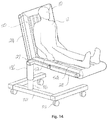
- FIG. 14 is a perspective view of the lifting system of FIGS. 10 to 13 reconfigured for supporting a subject in a seated position with legs outstretched.
- FIG. 15 shows the lifting system of FIG. 12 transitioning from a seated position to an upright configuration to assist the subject to stand.
- FIG. 16 is a perspective view of the lifting system of FIGS. 10 to 13 modified with wheelchair wheels.
- FIG. 17 is a perspective view of the lifting system of FIGS. 10 to 13 with a mattress modified to allow showering or bathing of the subject.
- FIG. 18 is a perspective view of the lifting system of FIGS. 10 to 13 with a mattress modified with a mesh panel in the backrest, seat and leg rest portions for showering of the subject.
- FIG. 19 is an open rear door of a passenger vehicle revealing the rear passenger seats.
- FIG. 20 shows the subject supported on the mattress in the seated position in the rear passenger seat having been lifted into the vehicle by the lifting device of FIGS. 10 to 13 .
- FIGS. 1A and 1B show a platform in the form of an inflatable mattress 10 in a deflated state and an inflated state, respectively.
- Subject 12 is shown on mattress 10 .
- the inflatable mattress comprises air inlet/air outlet 14 and longitudinally aligned channel 16 .
- Channel 16 runs the length of mattress 10 , although it is generally obscured when mattress 10 is in the deflated state.
- mattress 10 When mattress 10 is inflated by pumping air through air inlet/outlet 14 , channel 16 is exposed. As shown in FIG. 1C , longitudinally disposed support element 18 may be inserted into channel 16 . While support element 18 may be inserted into channel 16 when mattress 10 is deflated, inflation of mattress 10 assists the insertion, especially when mattress 10 bears a weight, such as that provided by subject 12 .
- the combination of mattress 10 and support element 18 provides lifting system 19 in accordance with an embodiment of the present invention.
- Support element 18 comprises support element handles 22 at each end to assist in the lifting of the mattress with the subject thereon.
- the mattress may be lifted with optional mattress handles 17 .
- subject 12 may be lifted on the mattress 10 in the inflated or deflated state, as support element 18 can adequately support the subject when mattress 12 is deflated.
- This embodiment is therefore useful in situations where it is desirable to move or lift subject 12 on a rigid support.
- the subject will be lifted on mattress 10 in the inflated state as the inflated state can provide more support and comfort to subject 12 .
- FIG. 2A shows inflatable mattress 10 in accordance with another embodiment of the invention.
- Inflatable mattress 10 is shown in a deflated state and includes a series of longitudinal compartments 20 in fluid communication with each other. Compartments 20 are inflated by pumping air through air inlet/outlet 14 . Entries to laterally aligned channels 16 are provided in the side of mattress 10 , although they are generally obscured when mattress 10 is in the deflated state. Channels 16 run the width of mattress 10 .
- mattress 10 may be rolled when in the deflated state. Mattress 10 may also be folded, although is not illustrated. Rolling or folding mattress 10 allows for compact storage of mattress 10 and can also assist in the transfer of a subject onto mattress 10 as previously described herein.
- FIG. 2C shows mattress 10 of FIG. 2A and FIG. 2B in an inflated state and in use with laterally disposed support elements 18 .
- mattress 10 and support elements 18 provide lifting system 19 in accordance with an embodiment of the present invention.
- Support elements 18 are provided with handles 22 .
- handle 22 has a greater diameter than channel 16 . Therefore for each support element 18 , at least one handle is removable, such that support element 18 may be inserted from one side into channel 16 . Handle 22 may then be attached to the inserted support element 18 (e.g. by threaded engagement, snap-locking, etc.), thereby permitting support element 18 to be gripped at each end. Handles 22 can also prevent support element 18 from falling out of channel 16 .
- FIG. 2D shows mattress 10 of FIGS. 2A to 2C in an inflated state and in use with support elements 18 that are connected at each end to frames 24 .
- Mattress 10 is inflated and support elements are inserted as described above in relation to FIG. 2C .
- support elements 18 do not include handles, but rather connectors 25 for connecting to frames 24 .
- Connectors 25 are illustrated as holes in support elements 18 through which each frame 24 may be inserted.
- the holes may be provided in frames 24 with support elements 18 inserted therein.
- Other connectors 25 may be used that allow support elements 18 to be connected to frames 24 including, for example, snap locks, clamps, spigoted, semi-circular or purpose made connectors, connectors using locking or spring loaded pins to locate and maintain the connection, etc.
- Frames 24 may be retained in place by using stops (not illustrated) to prevent support elements 18 from disconnecting with frames 24 .
- mattress 10 may be lifted by frames 24 .
- Support elements 18 reinforce mattress 10 as it is lifted, particularly when lifted with a weight thereon.
- Compartments 20 provide longitudinal strength to mattress 10 , particularly between channels 16 .
- Lifting system 19 is particularly suitable for use as a stretcher.
- Frames 24 may comprise one or more lockable hinges 27 for moving mattress
- Lockable hinge 27 may be provided anywhere along frame 24 , although it is preferable that lockable hinge 27 is provided in line with one of the channels, thereby allowing mattress 10 to be bent around one of the channels (or support element 18 inserted therein).
- Channels 16 provide particularly suitable bending points as channel 16 has less air volume in mattress 10 directly above or below channel 16 . Therefore the amount of air displacement required for mattress 10 to bend around channel 16 is reduced, and the bend is therefore more easily facilitated.
- Support element 18 in channel 16 also provides support along the bend when mattress 10 is lifted with a weight thereon.
- FIG. 2E shows mattress 10 of FIG. 2D with the inflated mattress 10 in a bent configuration.
- Mattress 10 is moved between the unbent configuration of FIG. 2D and the bent configuration of FIG. 2E by unlocking lockable hinges 27 and translationally moving, for example, support element 18 b relative to support element 18 c (i.e. about the longitudinal axis of support element 18 c ).
- Lockable hinges 27 are then locked, thereby retaining the mattress in the bent configuration.
- Mattress 10 may then be lifted in the bent configuration via frames 24 .
- frames 24 may be provided with a plurality of lockable hinges 27 , or the like, to allow mattress 10 to have different bent configurations (e.g. a seated configuration or a configuration to raise a subjects legs).
- FIG. 3A shows mattress 10 of FIGS. 2A to 2D in a deflated state on hospital bed 29 .
- Subject 12 has been placed on mattress 10 as described above (i.e. subject 12 is rolled on their side, mattress 10 in a semi rolled configuration is placed next to subject 12 , subject 12 is rolled onto their other side and onto the unrolled part of mattress 10 , the remaining rolled part of mattress 10 is unrolled and subject 12 is rolled back to their original position).
- Mattress 10 is inflated by pumping air from air compressor 36 through hose 38 and into mattress 10 through air inlet/outlet 14 , as shown in FIG. 3B , subsequently raising subject 12 and exposing the entries of channels 16 .
- Air compressor 36 is provided on lifting device 26 of lifting system 19 .
- Lifting device 26 includes cantilevered support legs 32 with wheels 34 attached thereto. Legs 32 allow lifting device 26 to be positioned close to hospital bed 29 and also provide the balance required for lifting system 26 to lift mattress 10 with subject 12 thereon. Once mattress 10 has been lifted from hospital bed 29 , the lifting device may be wheeled to another location (e.g. a surgical theatre, another bed, etc.). A support rail (not illustrated) may be attached to support elements 18 at the opposite end as lifting device 26 to ensure that subject 12 is retained on mattress 10 .
- mattress 10 has been placed, for example, on another bed using lifting system 26 , support elements 18 are removed and mattress 10 is deflated by opening air inlet/outlet 14 .
- Mattress 10 may be removed from under subject 12 in the deflated state by reversing the method used to place subject 12 on mattress 10 .
- Lifting system 26 can allow for all support elements 18 attached thereto to be lifted at the same time and over the same distance (i.e. the entire mattress 10 may be lifted vertically) or lifting system 26 can allow for independent parallel translational movement of one or more support elements 18 .
- FIGS. 3C and 3D are shown without hospital bed 29 and subject 12 for ease of illustration.
- FIG. 3C shows mattress 10 in an unbent configuration and attached to lifting device 26 via support elements 18 .
- the support elements 18 act as cantilevers.
- individual support elements 18 may be lifted to move mattress 10 from the unbent configuration to a bent configuration or between two different bent configurations, as illustrated in FIG. 3D .
- lifting device 26 may be used to move subject 12 from a reclined position to a seated position.
- Providing adjustable mattress configurations can aid in the comfort of subject 12 as well as offering health benefits e.g. it may be used to relieve pain or swelling, offset acid reflux, offset heartburn, improve digestion, improve breathing, relieve the heart muscle or stomach muscles, provide passive stretching, etc.
- lifting device 26 allows independent operation of hoisting machinery 30
- lifting device 26 in conjunction with mattress 10 can also be used to lift subjects from beds that have seated or other configurations or transfer subjects to beds that have seated or other configurations.
- Lifting device 26 as shown allows for vertical actuation of support elements 18 attached thereto.
- Other lifting devices may be used that allow vertical and horizontal actuation of support elements 18 e.g. other lifting devices may be used to parallel translationally move one or more support elements about a longitudinal axis of another support element.
- mattress 10 is illustrated with longitudinal compartments 20 and a single air inlet/outlet, it will be appreciated that different mattresses with different compartment and valve arrangements (e.g. multi-valves) may be used.
- different compartment arrangements and/or selective inflation of different compartments may be used to support the needs of different patients.
- Colour-coding or other marking of the compartments and/or valves can assist users in the selective inflation of the compartments and/or in the selection of an appropriate mattress for different patients.
- FIG. 4A shows inflatable mattress 10 in an inflated state and in accordance with another embodiment of the present invention.
- Mattress 10 is particularly suitable for lifting subjects from seats or wheelchairs.
- Mattress 10 may include back portion 40 or may be substantially flat. Back portion 40 provides additional support when a subject is lifted on to mattress 10 .
- Mattress 10 includes compartments 20 to provide support between channels 16 .
- Support elements 18 include attachments 46 that may be attached to a suitable lifting device (not illustrated). Suitable lifting devices are disclosed in the prior art including, for example, U.S. Pat. Nos. 3,694,829, 6,637,610 and 6,938,285, and WO/2006/032108. Attachments 46 may comprise, for example, hooks, holes or the like that allow support elements 18 to be attached to the lifting device. Alternatively, support elements 18 may be provided with handles (not illustrated) that enable lifting without a lifting device.
- FIG. 4C shows mattress 10 being used for a subject 10 in a wheelchair 44 .
- Subject 10 is sitting on mattress 10 in an inflated state and support elements 18 have been inserted into channels 16 .
- Support elements 18 may be attached to a suitable lifting device (not illustrated) and mattress 10 lifted thereby.
- Back portion 40 provides rear support to subject 12 when mattress 10 is lifted.
- support elements 18 may be detached from the lifting device and removed from mattress 10 .
- mattress 10 is then deflated.
- mattress 10 does not require rigid support components, mattress 10 in its deflated state will not cause subject 12 significant discomfort. Accordingly, subject 10 may remain seated on the mattress 10 for a prolonged period (e.g. the duration of a plane flight).
- mattress 10 may be incorporated into the subject's clothing (not illustrated).
- FIGS. 5A to 5G illustrate an alternative embodiment of a lifting system 126 .
- the lifting system 126 includes a lower frame 102 having wheels or casters 104 .
- a vertical support 106 extends from the lower frame 102 .
- the vertical support 106 connects with a support frame 124 via sleeve 128 extending from the support frame 124 .
- the sleeve 128 can be slid along the height of the vertical support 106 and locked into a selected height position.
- the support frame 124 releasably carries support elements 118 .
- the support elements 118 are received in channels through the mattress 110 when the mattress 110 is in an inflated state.
- the support elements 118 in this arrangement, act as cantilevers.
- the support frame 124 includes lockable hinge portions 127 which allows the support frame 124 to adopt different configurations. In effect, this allows the support elements 118 to be parallel translationally moved with respect to one another; which, in turn, causes the mattress 110 to adopt different configurations, see FIGS. 5B, 5D and 5E
- the lifting system 126 is shown with a pair of large wheels 144 arranged on a common axle member 146 .
- the axle member 146 is arranged to be releasably attached to the vertical support 106 via a clamp 150 . Consequently, the large wheels 144 can be selectively removed from the system 126 if, or when, they are not required.
- the axle member 146 can be reoriented by pivoting around the clamp 150 to change the position of the large wheels 144 , see FIG. 5F .
- the large wheels 144 allow a subject 112 to manually maneuver the system 126 , particularly when the support frame 124 is configured to adopt a sitting position, thereby acting like a wheel chair.
- the axle member 146 includes an additional strut support 148 for attachment to ends of support members 118 .
- the wheels or casters 104 are adapted to be moved within recesses in the lower frame 102 (refer to FIGS. 5F and 5G ). Hence, when the wheels 104 are retained within these recesses and the sleeve 128 is moved to the lowest position on vertical support 106 , the mattress is positioned as close to the ground as possible (see FIG. 5G ).
- the mattress 110 differs from previous embodiments by the inclusion of thin stiffeners 130 , shown clearly in FIG. 6 .
- the stiffeners 130 can be made of any suitable flexible but strong material, such as carbon fibre.
- the stiffeners 130 can be bonded to the inside top of the mattress 110 by any suitable means, for example gluing or stitching.
- the upper fabric of the mattress could incorporate channels in which the stiffeners 130 can be inserted during manufacture.
- the stiffeners 130 offer additional support to a subject 112 and also a degree of rigidity to the mattress 110 when in a deflated state.
- FIGS. 7, 8, 9A and 9B Variations on the mattress embodiment are shown in FIGS. 7, 8, 9A and 9B .
- the mattress 210 includes mesh panels 212 . This offers a water permeable version of the mattress which would be particularly suited for bathing purposes.
- FIG. 8 illustrates an embodiment of the mattress 310 having an orifice 312 suitably positioned to offer a toileting option for a subject, whereby a suitable waste catching receptacle could be arranged within or underneath the orifice 312 .
- FIGS. 9A and 9B illustrate a mattress 400 .
- the mattress 400 includes lateral supports 402 that extend laterally across the width of the mattress 400 .
- a lateral support 402 is preferably located adjacent the upper most edge of the mattress and/or at or adjacent to each folding/bending position of the mattress 400 .
- the lateral supports 402 are preferably located within a channel or sleeve formed within the mattress 400 .
- the lateral supports 402 serve to define the top, middle, lower and foot panels 406 a , 406 b , 406 c , 406 d of the mattress 400 .
- the mattress 400 further includes side panels 404 which are inflatable.
- the side panels 404 are preferably arranged to be foldable with respect to adjacent respective top, middle, lower and foot panels 406 a , 406 b , 406 c , 406 d .
- the side panels 404 When inflated, the side panels 404 preferably extend substantially perpendicularly to the plane of the adjacent top, middle and lower panels 406 a , 406 b , 406 c , although a range of other angles are envisaged.
- the inflatable side panels 404 provide restraint and lateral support for the user and also provide stabilizing support for the mattress 400 . In this manner, the inflated side panels 404 act as “beams” and the load of the user can be effectively supported on the “beams” of the mattress 400 during lifting.
- the mattress 400 is fitted with a longitudinal joining device 408 that extends along at least a part of the middle panel 406 b , lower panel 406 c and foot panel 406 d .
- the joining device 408 is preferably a zipper or a hook and loop type fastener connection.
- the inclusion of the joining device 408 is advantageous because when released the middle and lower panels 406 c can be split to facilitate placement of a user on the mattress 400 . This is particularly useful when the user is sitting in an upright position such as when on a chair.
- the mattress 400 is also fitted with a toileting aperture.
- the aperture may be established by a panel 410 which can be folded or otherwise moved out of the way to effectively open the aperture in the middle panel 406 b .
- the middle panel 406 b provides the seat surface when the mattress 400 is folded into a seated configuration as shown in FIG. 9B .
- the panel 410 may be an inflatable panel which includes an opening that is revealed/opened when the panel 410 is deflated and closed when the panel is inflated.
- the mattress 400 preferably includes foot panel 406 d .
- the foot panel 406 d establishes a surface which the user may press against to enable adjustment of their positioning on the mattress 400 .
- the foot panel 406 d may be inflatable and is preferably of sufficient rigidity to enable the user to press against it and thereby adjust their body position on the mattress 400 .
- the mattress 400 shown in FIGS. 9A and 9B may be made of a range of different materials. However, it is envisaged that at least the top, middle and lower panels 406 a , 406 b , 406 c of the mattress 400 include a top layer, a bottom layer and an intermediate spacer layer made of a spacer fabric. Such an arrangement enables the top, middle and lower panels 406 a , 406 b , 406 c of the mattress 400 to be inflatable. The use of such a spacer layer negates the need to use baffles within the mattress 400 whilst allowing much higher inflation pressures to be used. This allows the mattress to be thinner than otherwise possible.
- a spacer fabric is a fabric made from a complex three dimensional construction made of two or more separate fabric layers connected vertically with the pile yarns or fabric layers keeping hollow space between adjacent connecting yarns or layers. Spacer fabrics are manufactured using methods such as weaving, braiding, stitching, warp knitting and weft knitting.
- a preferred form of spacer fabric for use in a mattress according to an embodiment of the invention is a “drop stitch” fabric (commonly used for inflatable stand-up paddle boards).
- the spacer layer is preferably made from a drop stich material.
- a wicking layer could also be incorporated to facilitate draw of perspiration and other liquids away from the body of the users.
- Section A through the mattress 400 of FIG. 9B is shown in FIG. 9C .
- the mattress 400 is inflated and is shown formed from drop stitch material comprising woven top and bottom layers 411 and 412 , and a gas impermeable skin 414 bonded to the outer surface of the top and bottom layers 411 , 412 .
- Interconnected threads 416 of predetermined length are sandwiched between the top and bottom layers 411 , 412 .
- top, middle and bottom panels of the mattress need not necessarily be inflatable, whilst the side panels would be inflatable.
- FIGS. 10 to 20 depict versions of the system readily suitable for lifting a subject from bed and transferring them to the passenger seat of a vehicle.
- FIG. 10 shows a platform for the lifting system, the platform being in the form of an inflatable mattress 10 with four attachment structures in the form of lateral channels 16 spaced along the length of the mattress 10 .
- the top of the mattress 10 provides the elongate platform surface 101 to support the patient.
- This platform surface 101 has a back rest portion 50 , a seat portion 52 and leg rest portion 54 which dictates the orientation of the deflated mattress 10 when it is folded (or rolled or concertinaed) and laid next to the patient in bed (i.e. the back rest portion 50 adjacent the upper body).
- FIG. 11 shows the lifting device 26 for the lifting system.
- the lifting device has four cantilevered tynes 18 that slide into the lateral channels 16 of the mattress 10 .
- the tynes 18 are cantilevered from a support frame 24 which in turn is movably mounted to a vertical support 36 via the sleeve 28 .
- the vertical support is rigidly fixed to the lower frame 32 with a broad base for stability and lockable castors 34 for convenient movement.
- a suitable lift actuator (not shown) acts on the sleeve 28 or other part of the support frame 24 to lift and lower the mattress 10 while cantilevered on the tynes 18 .
- suitable lift actuators may be pneumatic, hydraulic, mechanical (e.g.
- the lift actuator selected will need to have a load capacity well in excess of the weight of the patient, and any ancillary equipment they may carry with them.
- FIG. 12 shows the mattress 10 being reconfigured by the lifting device 26 to support a subject 12 in a seated position.
- the support frame 24 has lockable hinges 27 at the cantilevered mounting points for the two inner tynes 18 . This allows relative movement of the tynes 18 such that the leg rest portion 54 , seat portion 52 and backrest portion 50 of the mattress 10 are in a chair configuration.
- FIG. 13 shows the mattress 10 selectively configured by the lifting device 26 to support the patient 12 in a supine position.
- the hinges 27 are adjusted and locked to position the tynes 18 such that the leg rest portion 54 , seat portion 52 and backrest portion 50 of the platform surface 101 are in a flat configuration.
- FIG. 14 shows a further alternative with the patient 12 supported on the mattress 10 in a seated position with legs outstretched.
- FIG. 14 also shows a form of the support frame 24 with a lift cylinder 136 to telescopically engage the vertical support 36 to hydraulically, pneumatically or electrically lift and lower the support frame 24 .
- the control interface (not shown) may be operated by the patient 12 , possible via remote control or personal smart device. More sophisticated versions will provide powered operation of the adjustable/lockable hinges 27 providing the patient 12 with greater levels of autonomy.
- FIG. 15 shows the lifting system being used to transition a patient from a seated position to a standing position.
- the lift cylinder 136 elevates the support frame 24 and the adjustable hinges 27 move the back rest portion 50 , the seat portion 52 and the leg rest 54 guides the patient's feet 112 towards the unobstructed ground 132 within the lower frame 32 . With feet on the ground, the patient 12 need only straighten their legs and ease away from the mattress 10 into a standing position.
- FIG. 17 shows the mattress 10 and lifting device 26 of the system interengaged, without the patient, and with the cantilevered tynes 18 shown in ghost line.
- FIG. 16 is an arrangement of the lifting system modified to include wheelchair wheels, similar to the embodiment shown in FIGS. 5A to 5F .
- the wheelchair wheels 44 can be selectively engaged or disengaged from the ground using the lift cylinder 136 via the wheel axle 144 . This provides the patient 12 with the option to self-ambulate and greater independence.
- FIG. 18 is a perspective view of the lifting system with a mattress 10 modified to allow showering or bathing. Similar to the embodiment shown in FIG. 7 , the mattress 10 has a back rest portion 50 , seat portion 52 and leg rest portion 54 with inflatable peripheries 210 . Within the peripheries, is a mesh material 212 for draining water and quick drying to assist with washing the patient 12 . The cantilevered tynes 18 still extend through channels 16 (see FIG. 17 ) defined by the inflatable peripheries 210 .
- FIG. 19 is a passenger vehicle 56 with open side door 58 revealing the rear passenger seats 60 .
- These types of sliding van doors 58 provide good access to the seats and are often preferred for the transport of people with impaired mobility. It will appreciated that the cantilevered support of the mattress 10 by the lifting device 26 is well suited to guiding the patient 12 into the vehicle 56 , lowering the mattress 10 onto the seat 60 , and simply removing the tynes 18 (from the lifting device 26 or the mattress 10 ).
- FIG. 20 shows the subject 12 supported on the mattress 10 in the seated position in the rear passenger seat 60 .
- the inflatable mattress conforms to the contours of the seat and will not obstruct the lap/sash seat belt, or seat belt clasp.
Landscapes
- Health & Medical Sciences (AREA)
- Life Sciences & Earth Sciences (AREA)
- Animal Behavior & Ethology (AREA)
- General Health & Medical Sciences (AREA)
- Public Health (AREA)
- Veterinary Medicine (AREA)
- Nursing (AREA)
- Rehabilitation Therapy (AREA)
- Invalid Beds And Related Equipment (AREA)
Abstract
Description
-
- a platform for supporting the subject, the platform having an elongate platform surface selectively configurable in a flexible state allowing the elongate platform surface to fold about a longitudinal line for positioning the platform beneath the subject, and a rigid state to support the subject in the desired position, the platform also having one or more attachment structures; and,
- a lifting device for detachably engaging the one or more attachment structures to elevate and lower the platform cantilevered from the lifting device.
-
- eye gaze,
- breath control,
- voice recognition, and
- joystick manipulation.
-
- providing a platform for supporting the subject, the platform having one or more attachment structures and an elongate platform surface selectively configurable in a flexible state allowing the elongate platform surface to fold about a longitudinal line, a rigid state to support the subject in the desired position;
- positioning the subject to lie on one side;
- positioning the platform in a flexible state alongside the subject such that the fold is closely adjacent the subject's back;
- rolling the subject to their opposing side onto the platform surface;
- unfolding the platform surface such that the platform surface extends beneath the subject;
- configuring the platform surface into the rigid state; and,
- providing a lifting device for detachably engaging the one or more attachment structures to elevate and lower the platform cantilevered from the lifting device.
-
- i. placing the deflated mattress next to the subject, whereby the deflated mattress is partially or fully rolled up and the subject is on their side;
- ii. unrolling part of the deflated mattress if the deflated mattress is fully rolled up;
- iii. rolling the subject onto the unrolled part of the deflated mattress;
- iv. unrolling the remaining part of the deflated mattress.
Claims (12)
Applications Claiming Priority (5)
| Application Number | Priority Date | Filing Date | Title |
|---|---|---|---|
| AU2016904439A AU2016904439A0 (en) | 2016-10-31 | Inflatable Mattress and Lifting System | |
| AU2016904439 | 2016-10-31 | ||
| AU2017902474 | 2017-06-27 | ||
| AU2017902474A AU2017902474A0 (en) | 2017-06-27 | Lifting system with lifting device and cantilievered support platform | |
| PCT/AU2017/051196 WO2018076076A1 (en) | 2016-10-31 | 2017-10-31 | Lifting system with lifting device and cantilievered support platform |
Publications (2)
| Publication Number | Publication Date |
|---|---|
| US20200146912A1 US20200146912A1 (en) | 2020-05-14 |
| US11103403B2 true US11103403B2 (en) | 2021-08-31 |
Family
ID=62022973
Family Applications (1)
| Application Number | Title | Priority Date | Filing Date |
|---|---|---|---|
| US16/345,233 Active US11103403B2 (en) | 2016-10-31 | 2017-10-31 | Lifting system with lifting device and cantilevered support platform |
Country Status (7)
| Country | Link |
|---|---|
| US (1) | US11103403B2 (en) |
| EP (1) | EP3522846B1 (en) |
| JP (1) | JP7117589B2 (en) |
| CN (1) | CN109952084B (en) |
| AU (1) | AU2017351746B2 (en) |
| CA (1) | CA3036105A1 (en) |
| WO (1) | WO2018076076A1 (en) |
Families Citing this family (6)
| Publication number | Priority date | Publication date | Assignee | Title |
|---|---|---|---|---|
| WO2019174579A1 (en) * | 2018-03-14 | 2019-09-19 | Ka Shek Neville Lee | Patient transfer system |
| US10967763B2 (en) * | 2019-03-21 | 2021-04-06 | Pratt & Miller Engineering and Fabrication, Inc. | Removable and convertible seat assembly |
| EP3754066B1 (en) * | 2019-06-20 | 2024-06-05 | Volvo Car Corporation | Inflatable structure |
| CN110638591B (en) * | 2019-10-10 | 2021-07-30 | 高斌 | Translating patient device |
| JP6966829B1 (en) * | 2020-06-02 | 2021-11-17 | 株式会社メルカリ | Mobile |
| CN115737306A (en) * | 2022-11-22 | 2023-03-07 | 北京华商慧智居家养老服务有限公司 | Portable nursing device |
Citations (12)
| Publication number | Priority date | Publication date | Assignee | Title |
|---|---|---|---|---|
| US20010044966A1 (en) | 2000-03-23 | 2001-11-29 | Linger David R. | Large body stretcher |
| GB2381256A (en) | 2001-09-29 | 2003-04-30 | Collette Fellows-Smith | Patient lifting device |
| US6854137B2 (en) * | 2002-02-18 | 2005-02-15 | Daniel T. Johnson | Patient transfer and transport bed |
| US20050135907A1 (en) | 2003-11-24 | 2005-06-23 | Romano James P. | Medical lift and transport system, method and apparatus |
| US20060218724A1 (en) | 2005-04-01 | 2006-10-05 | Jerry Blevins | Bed having tiltable section |
| US7487559B1 (en) * | 2004-10-05 | 2009-02-10 | Denosky James M | Patient transfer device |
| US20090276955A1 (en) | 2005-03-14 | 2009-11-12 | Ergo-Asyst Technology Llc | Patient transfer system with associated frames and lift carts |
| WO2012001423A2 (en) | 2010-07-01 | 2012-01-05 | Mangar International (Holdings) Limited | Person transfer apparatus |
| US20120023660A1 (en) * | 2010-07-30 | 2012-02-02 | Illinois Institute Of Technology | Robotic Posture Transfer Assist Devices and Methods |
| EP2415444A2 (en) | 2010-08-05 | 2012-02-08 | Mangar International (Holdings) Limited | Person transfer apparatus |
| US20160057971A1 (en) * | 2013-04-15 | 2016-03-03 | Promat Inc. | Cushioning device for large animals |
| GB2529954A (en) | 2015-01-15 | 2016-03-09 | David E T Garman Concepts Ltd | Inflatable patient cradle, patient handling system and method |
Family Cites Families (25)
| Publication number | Priority date | Publication date | Assignee | Title |
|---|---|---|---|---|
| US3593351A (en) * | 1969-08-14 | 1971-07-20 | Benjamin A Dove | Patient transfer device |
| US3694829A (en) | 1970-03-18 | 1972-10-03 | Johannes Petrus Bakker | Patient lifting apparatus |
| JPS6019251B2 (en) * | 1977-01-26 | 1985-05-15 | 茂 渡辺 | nursing equipment |
| JPS59186009A (en) * | 1983-04-07 | 1984-10-22 | Sumitomo Electric Ind Ltd | Centralized supervisory controlling system of shifting assistance |
| GB8925950D0 (en) * | 1989-11-16 | 1990-01-04 | Fulmer Systems Ltd | Improvements in or relating to a transfer trolley |
| GB9124945D0 (en) * | 1991-11-23 | 1992-01-22 | Mangar Aids Ltd | Load supporting apparatus |
| FR2699070B1 (en) * | 1992-12-11 | 1995-03-24 | Eif | Improved stretcher. |
| US5540321A (en) * | 1994-08-19 | 1996-07-30 | Foster; Wilbur | Apparatus and method for moving objects |
| JP3628149B2 (en) * | 1997-06-25 | 2005-03-09 | アキレス株式会社 | mattress |
| AU2000276354A1 (en) | 1997-11-05 | 2002-04-15 | Sunnybrook And Women's College Health Sciences Centre | Patient transfer device |
| EP1126810A1 (en) | 1998-11-06 | 2001-08-29 | Robert G. Cheeseboro | Personal transporter |
| DE60323137D1 (en) * | 2002-11-12 | 2008-10-02 | Gray Tek Inc | MATERIAL DRIVE WITH A LIQUID FILM MEMORY |
| KR200322778Y1 (en) * | 2003-04-30 | 2003-08-14 | 남철우 | A stretcher have many uses |
| JP2005021705A (en) * | 2004-07-21 | 2005-01-27 | Fumio Tanaka | Care bath with crane to enable bather to bathe as lying |
| DK1804753T3 (en) | 2004-09-24 | 2015-02-09 | Haycomp Pty Ltd | Apparatus for the transfer of a person from a wheelchair to a permanent seat |
| DE602006004600D1 (en) * | 2005-08-01 | 2009-02-12 | Ergo Asyst Technology Llc | PATIENT MANAGEMENT SYSTEM |
| JP4555770B2 (en) * | 2005-12-07 | 2010-10-06 | 朝典 鈴木 | stretcher |
| GB0625395D0 (en) * | 2006-12-20 | 2007-02-07 | Cintec Int Ltd | Combined blast protection structure and vehicle barrier |
| CN201073396Y (en) * | 2007-12-26 | 2008-06-18 | 山东省千佛山医院 | Medical over bed |
| US10143609B2 (en) * | 2011-06-14 | 2018-12-04 | Picard Healthcare Technology (Dongguan) Co. Ltd. | Medical air mattress |
| US9228885B2 (en) * | 2012-06-21 | 2016-01-05 | Hill-Rom Services, Inc. | Patient support systems and methods of use |
| JP6017686B2 (en) * | 2012-06-21 | 2016-11-02 | ヒル−ロム サービシズ,インコーポレイテッド | Patient holding system and method of use |
| KR101486881B1 (en) * | 2012-10-11 | 2015-01-29 | 한국생산기술연구원 | Moving Type Lifting Apparatus Including Torque Adjustable Driving Assistance Unit |
| CN204709243U (en) * | 2015-05-29 | 2015-10-21 | 浙江师范大学 | A kind of multifunctional dolly for patient tranfer nursing transport |
| CN205434169U (en) * | 2015-12-21 | 2016-08-10 | 云南巨能科技发展有限公司 | Human transfer device |
-
2017
- 2017-10-31 EP EP17865915.7A patent/EP3522846B1/en active Active
- 2017-10-31 CN CN201780067256.6A patent/CN109952084B/en active Active
- 2017-10-31 JP JP2019544940A patent/JP7117589B2/en active Active
- 2017-10-31 AU AU2017351746A patent/AU2017351746B2/en active Active
- 2017-10-31 US US16/345,233 patent/US11103403B2/en active Active
- 2017-10-31 WO PCT/AU2017/051196 patent/WO2018076076A1/en active Search and Examination
- 2017-10-31 CA CA3036105A patent/CA3036105A1/en active Pending
Patent Citations (12)
| Publication number | Priority date | Publication date | Assignee | Title |
|---|---|---|---|---|
| US20010044966A1 (en) | 2000-03-23 | 2001-11-29 | Linger David R. | Large body stretcher |
| GB2381256A (en) | 2001-09-29 | 2003-04-30 | Collette Fellows-Smith | Patient lifting device |
| US6854137B2 (en) * | 2002-02-18 | 2005-02-15 | Daniel T. Johnson | Patient transfer and transport bed |
| US20050135907A1 (en) | 2003-11-24 | 2005-06-23 | Romano James P. | Medical lift and transport system, method and apparatus |
| US7487559B1 (en) * | 2004-10-05 | 2009-02-10 | Denosky James M | Patient transfer device |
| US20090276955A1 (en) | 2005-03-14 | 2009-11-12 | Ergo-Asyst Technology Llc | Patient transfer system with associated frames and lift carts |
| US20060218724A1 (en) | 2005-04-01 | 2006-10-05 | Jerry Blevins | Bed having tiltable section |
| WO2012001423A2 (en) | 2010-07-01 | 2012-01-05 | Mangar International (Holdings) Limited | Person transfer apparatus |
| US20120023660A1 (en) * | 2010-07-30 | 2012-02-02 | Illinois Institute Of Technology | Robotic Posture Transfer Assist Devices and Methods |
| EP2415444A2 (en) | 2010-08-05 | 2012-02-08 | Mangar International (Holdings) Limited | Person transfer apparatus |
| US20160057971A1 (en) * | 2013-04-15 | 2016-03-03 | Promat Inc. | Cushioning device for large animals |
| GB2529954A (en) | 2015-01-15 | 2016-03-09 | David E T Garman Concepts Ltd | Inflatable patient cradle, patient handling system and method |
Non-Patent Citations (4)
| Title |
|---|
| International Preliminary Report on Patentability for International Application No. PCT/AU2017/051196, Date of Filing: Oct. 31, 2017, Applicant: Margaret Forshaw Gillespie, dated Oct. 31, 2018, 17 pages. |
| International Search Report for International Application No. PCT/AU2017/051196, Date of Filing: Oct. 31, 2017, Applicant: Margaret Forshaw Gillespie, dated Dec. 4, 2017, 4 pages. |
| Supplementary Partial European Search Report received for copending European Patent Application No. EP17865915, Date of Completion of Search: Aug. 7, 2019, 8 pages. |
| Written Opinion for International Application No. PCT/AU2017/051196, Date of Filing: Oct. 31, 2017, Applicant: Margaret Forshaw Gillespie, dated Dec. 4, 2017, 6 pages. |
Also Published As
| Publication number | Publication date |
|---|---|
| WO2018076076A1 (en) | 2018-05-03 |
| EP3522846A1 (en) | 2019-08-14 |
| AU2017351746B2 (en) | 2021-09-30 |
| US20200146912A1 (en) | 2020-05-14 |
| EP3522846A4 (en) | 2019-12-18 |
| EP3522846B1 (en) | 2024-09-18 |
| CN109952084B (en) | 2021-08-20 |
| CN109952084A (en) | 2019-06-28 |
| JP7117589B2 (en) | 2022-08-15 |
| AU2017351746A1 (en) | 2019-04-04 |
| JP2020503986A (en) | 2020-02-06 |
| CA3036105A1 (en) | 2018-05-03 |
Similar Documents
| Publication | Publication Date | Title |
|---|---|---|
| US11103403B2 (en) | Lifting system with lifting device and cantilevered support platform | |
| US7487559B1 (en) | Patient transfer device | |
| US7197778B2 (en) | Patient transfer system | |
| EP2055284B1 (en) | A rescuing and carrying device | |
| US5280657A (en) | Sheet position adjustment assembly and method | |
| US5634222A (en) | Cardiopulmonary resuscitation back support | |
| EP0691116A2 (en) | Medical lifting devices | |
| CA3049507C (en) | Patient handling apparatus and method | |
| US12042455B2 (en) | Patient transport apparatus | |
| WO2001089978A1 (en) | An aid for lifting and carrying a mass/object | |
| US10806652B1 (en) | Patient-turning assemblies | |
| GB2540698A (en) | Inflatable patient cradle, patient handling system and method | |
| US20190117502A1 (en) | Patient Support Apparatus for Releasably Securing a Chest Compression System | |
| WO2012001423A2 (en) | Person transfer apparatus | |
| US20060236453A1 (en) | Equipment for moving patient without changing patient's pose | |
| CN210872537U (en) | Medical shovel type stretcher wheelchair | |
| GB2296429A (en) | Inflatable lifting seat | |
| IT201800006237A1 (en) | Stretcher |
Legal Events
| Date | Code | Title | Description |
|---|---|---|---|
| FEPP | Fee payment procedure |
Free format text: ENTITY STATUS SET TO UNDISCOUNTED (ORIGINAL EVENT CODE: BIG.); ENTITY STATUS OF PATENT OWNER: SMALL ENTITY |
|
| FEPP | Fee payment procedure |
Free format text: PETITION RELATED TO MAINTENANCE FEES GRANTED (ORIGINAL EVENT CODE: PTGR); ENTITY STATUS OF PATENT OWNER: SMALL ENTITY |
|
| AS | Assignment |
Owner name: GILLESPIE, MARGARET FORSHAW, AUSTRALIA Free format text: ASSIGNMENT OF ASSIGNORS INTEREST;ASSIGNOR:GILLESPIE, BRUCE ROME;REEL/FRAME:050108/0327 Effective date: 20190505 |
|
| FEPP | Fee payment procedure |
Free format text: ENTITY STATUS SET TO SMALL (ORIGINAL EVENT CODE: SMAL); ENTITY STATUS OF PATENT OWNER: SMALL ENTITY |
|
| AS | Assignment |
Owner name: VALLUGA HOLDINGS PTY LTD, AUSTRALIA Free format text: ASSIGNMENT OF ASSIGNORS INTEREST;ASSIGNOR:GILLESPIE, MARGARET FORSHAW;REEL/FRAME:053698/0798 Effective date: 20200818 |
|
| STPP | Information on status: patent application and granting procedure in general |
Free format text: RESPONSE TO NON-FINAL OFFICE ACTION ENTERED AND FORWARDED TO EXAMINER |
|
| STPP | Information on status: patent application and granting procedure in general |
Free format text: DOCKETED NEW CASE - READY FOR EXAMINATION |
|
| STPP | Information on status: patent application and granting procedure in general |
Free format text: NOTICE OF ALLOWANCE MAILED -- APPLICATION RECEIVED IN OFFICE OF PUBLICATIONS |
|
| STPP | Information on status: patent application and granting procedure in general |
Free format text: PUBLICATIONS -- ISSUE FEE PAYMENT RECEIVED |
|
| STPP | Information on status: patent application and granting procedure in general |
Free format text: PUBLICATIONS -- ISSUE FEE PAYMENT VERIFIED |
|
| STCF | Information on status: patent grant |
Free format text: PATENTED CASE |