US11097985B2 - Carbon composite composition and carbon heater manufactured using the same - Google Patents
Carbon composite composition and carbon heater manufactured using the same Download PDFInfo
- Publication number
- US11097985B2 US11097985B2 US15/975,348 US201815975348A US11097985B2 US 11097985 B2 US11097985 B2 US 11097985B2 US 201815975348 A US201815975348 A US 201815975348A US 11097985 B2 US11097985 B2 US 11097985B2
- Authority
- US
- United States
- Prior art keywords
- carbon
- carbon composite
- composition
- composite composition
- heater
- Prior art date
- Legal status (The legal status is an assumption and is not a legal conclusion. Google has not performed a legal analysis and makes no representation as to the accuracy of the status listed.)
- Active, expires
Links
Images


Classifications
-
- C—CHEMISTRY; METALLURGY
- C04—CEMENTS; CONCRETE; ARTIFICIAL STONE; CERAMICS; REFRACTORIES
- C04B—LIME, MAGNESIA; SLAG; CEMENTS; COMPOSITIONS THEREOF, e.g. MORTARS, CONCRETE OR LIKE BUILDING MATERIALS; ARTIFICIAL STONE; CERAMICS; REFRACTORIES; TREATMENT OF NATURAL STONE
- C04B35/00—Shaped ceramic products characterised by their composition; Ceramics compositions; Processing powders of inorganic compounds preparatory to the manufacturing of ceramic products
- C04B35/515—Shaped ceramic products characterised by their composition; Ceramics compositions; Processing powders of inorganic compounds preparatory to the manufacturing of ceramic products based on non-oxide ceramics
- C04B35/56—Shaped ceramic products characterised by their composition; Ceramics compositions; Processing powders of inorganic compounds preparatory to the manufacturing of ceramic products based on non-oxide ceramics based on carbides or oxycarbides
- C04B35/565—Shaped ceramic products characterised by their composition; Ceramics compositions; Processing powders of inorganic compounds preparatory to the manufacturing of ceramic products based on non-oxide ceramics based on carbides or oxycarbides based on silicon carbide
-
- C—CHEMISTRY; METALLURGY
- C04—CEMENTS; CONCRETE; ARTIFICIAL STONE; CERAMICS; REFRACTORIES
- C04B—LIME, MAGNESIA; SLAG; CEMENTS; COMPOSITIONS THEREOF, e.g. MORTARS, CONCRETE OR LIKE BUILDING MATERIALS; ARTIFICIAL STONE; CERAMICS; REFRACTORIES; TREATMENT OF NATURAL STONE
- C04B35/00—Shaped ceramic products characterised by their composition; Ceramics compositions; Processing powders of inorganic compounds preparatory to the manufacturing of ceramic products
- C04B35/622—Forming processes; Processing powders of inorganic compounds preparatory to the manufacturing of ceramic products
- C04B35/626—Preparing or treating the powders individually or as batches ; preparing or treating macroscopic reinforcing agents for ceramic products, e.g. fibres; mechanical aspects section B
- C04B35/63—Preparing or treating the powders individually or as batches ; preparing or treating macroscopic reinforcing agents for ceramic products, e.g. fibres; mechanical aspects section B using additives specially adapted for forming the products, e.g.. binder binders
- C04B35/6303—Inorganic additives
-
- C—CHEMISTRY; METALLURGY
- C04—CEMENTS; CONCRETE; ARTIFICIAL STONE; CERAMICS; REFRACTORIES
- C04B—LIME, MAGNESIA; SLAG; CEMENTS; COMPOSITIONS THEREOF, e.g. MORTARS, CONCRETE OR LIKE BUILDING MATERIALS; ARTIFICIAL STONE; CERAMICS; REFRACTORIES; TREATMENT OF NATURAL STONE
- C04B35/00—Shaped ceramic products characterised by their composition; Ceramics compositions; Processing powders of inorganic compounds preparatory to the manufacturing of ceramic products
- C04B35/622—Forming processes; Processing powders of inorganic compounds preparatory to the manufacturing of ceramic products
- C04B35/626—Preparing or treating the powders individually or as batches ; preparing or treating macroscopic reinforcing agents for ceramic products, e.g. fibres; mechanical aspects section B
- C04B35/63—Preparing or treating the powders individually or as batches ; preparing or treating macroscopic reinforcing agents for ceramic products, e.g. fibres; mechanical aspects section B using additives specially adapted for forming the products, e.g.. binder binders
- C04B35/632—Organic additives
- C04B35/634—Polymers
- C04B35/63448—Polymers obtained otherwise than by reactions only involving carbon-to-carbon unsaturated bonds
- C04B35/63472—Condensation polymers of aldehydes or ketones
- C04B35/63476—Phenol-formaldehyde condensation polymers
-
- H—ELECTRICITY
- H05—ELECTRIC TECHNIQUES NOT OTHERWISE PROVIDED FOR
- H05B—ELECTRIC HEATING; ELECTRIC LIGHT SOURCES NOT OTHERWISE PROVIDED FOR; CIRCUIT ARRANGEMENTS FOR ELECTRIC LIGHT SOURCES, IN GENERAL
- H05B3/00—Ohmic-resistance heating
- H05B3/10—Heater elements characterised by the composition or nature of the materials or by the arrangement of the conductor
- H05B3/12—Heater elements characterised by the composition or nature of the materials or by the arrangement of the conductor characterised by the composition or nature of the conductive material
- H05B3/14—Heater elements characterised by the composition or nature of the materials or by the arrangement of the conductor characterised by the composition or nature of the conductive material the material being non-metallic
- H05B3/145—Carbon only, e.g. carbon black, graphite
-
- H—ELECTRICITY
- H05—ELECTRIC TECHNIQUES NOT OTHERWISE PROVIDED FOR
- H05B—ELECTRIC HEATING; ELECTRIC LIGHT SOURCES NOT OTHERWISE PROVIDED FOR; CIRCUIT ARRANGEMENTS FOR ELECTRIC LIGHT SOURCES, IN GENERAL
- H05B3/00—Ohmic-resistance heating
- H05B3/10—Heater elements characterised by the composition or nature of the materials or by the arrangement of the conductor
- H05B3/12—Heater elements characterised by the composition or nature of the materials or by the arrangement of the conductor characterised by the composition or nature of the conductive material
- H05B3/14—Heater elements characterised by the composition or nature of the materials or by the arrangement of the conductor characterised by the composition or nature of the conductive material the material being non-metallic
- H05B3/148—Silicon, e.g. silicon carbide, magnesium silicide, heating transistors or diodes
-
- H—ELECTRICITY
- H05—ELECTRIC TECHNIQUES NOT OTHERWISE PROVIDED FOR
- H05B—ELECTRIC HEATING; ELECTRIC LIGHT SOURCES NOT OTHERWISE PROVIDED FOR; CIRCUIT ARRANGEMENTS FOR ELECTRIC LIGHT SOURCES, IN GENERAL
- H05B3/00—Ohmic-resistance heating
- H05B3/62—Heating elements specially adapted for furnaces
- H05B3/64—Heating elements specially adapted for furnaces using ribbon, rod, or wire heater
-
- C—CHEMISTRY; METALLURGY
- C04—CEMENTS; CONCRETE; ARTIFICIAL STONE; CERAMICS; REFRACTORIES
- C04B—LIME, MAGNESIA; SLAG; CEMENTS; COMPOSITIONS THEREOF, e.g. MORTARS, CONCRETE OR LIKE BUILDING MATERIALS; ARTIFICIAL STONE; CERAMICS; REFRACTORIES; TREATMENT OF NATURAL STONE
- C04B2235/00—Aspects relating to ceramic starting mixtures or sintered ceramic products
- C04B2235/02—Composition of constituents of the starting material or of secondary phases of the final product
- C04B2235/30—Constituents and secondary phases not being of a fibrous nature
- C04B2235/32—Metal oxides, mixed metal oxides, or oxide-forming salts thereof, e.g. carbonates, nitrates, (oxy)hydroxides, chlorides
- C04B2235/3217—Aluminum oxide or oxide forming salts thereof, e.g. bauxite, alpha-alumina
-
- C—CHEMISTRY; METALLURGY
- C04—CEMENTS; CONCRETE; ARTIFICIAL STONE; CERAMICS; REFRACTORIES
- C04B—LIME, MAGNESIA; SLAG; CEMENTS; COMPOSITIONS THEREOF, e.g. MORTARS, CONCRETE OR LIKE BUILDING MATERIALS; ARTIFICIAL STONE; CERAMICS; REFRACTORIES; TREATMENT OF NATURAL STONE
- C04B2235/00—Aspects relating to ceramic starting mixtures or sintered ceramic products
- C04B2235/02—Composition of constituents of the starting material or of secondary phases of the final product
- C04B2235/30—Constituents and secondary phases not being of a fibrous nature
- C04B2235/34—Non-metal oxides, non-metal mixed oxides, or salts thereof that form the non-metal oxides upon heating, e.g. carbonates, nitrates, (oxy)hydroxides, chlorides
- C04B2235/3418—Silicon oxide, silicic acids, or oxide forming salts thereof, e.g. silica sol, fused silica, silica fume, cristobalite, quartz or flint
-
- C—CHEMISTRY; METALLURGY
- C04—CEMENTS; CONCRETE; ARTIFICIAL STONE; CERAMICS; REFRACTORIES
- C04B—LIME, MAGNESIA; SLAG; CEMENTS; COMPOSITIONS THEREOF, e.g. MORTARS, CONCRETE OR LIKE BUILDING MATERIALS; ARTIFICIAL STONE; CERAMICS; REFRACTORIES; TREATMENT OF NATURAL STONE
- C04B2235/00—Aspects relating to ceramic starting mixtures or sintered ceramic products
- C04B2235/02—Composition of constituents of the starting material or of secondary phases of the final product
- C04B2235/30—Constituents and secondary phases not being of a fibrous nature
- C04B2235/38—Non-oxide ceramic constituents or additives
- C04B2235/3817—Carbides
- C04B2235/3826—Silicon carbides
-
- C—CHEMISTRY; METALLURGY
- C04—CEMENTS; CONCRETE; ARTIFICIAL STONE; CERAMICS; REFRACTORIES
- C04B—LIME, MAGNESIA; SLAG; CEMENTS; COMPOSITIONS THEREOF, e.g. MORTARS, CONCRETE OR LIKE BUILDING MATERIALS; ARTIFICIAL STONE; CERAMICS; REFRACTORIES; TREATMENT OF NATURAL STONE
- C04B2235/00—Aspects relating to ceramic starting mixtures or sintered ceramic products
- C04B2235/02—Composition of constituents of the starting material or of secondary phases of the final product
- C04B2235/30—Constituents and secondary phases not being of a fibrous nature
- C04B2235/42—Non metallic elements added as constituents or additives, e.g. sulfur, phosphor, selenium or tellurium
- C04B2235/422—Carbon
- C04B2235/425—Graphite
-
- C—CHEMISTRY; METALLURGY
- C04—CEMENTS; CONCRETE; ARTIFICIAL STONE; CERAMICS; REFRACTORIES
- C04B—LIME, MAGNESIA; SLAG; CEMENTS; COMPOSITIONS THEREOF, e.g. MORTARS, CONCRETE OR LIKE BUILDING MATERIALS; ARTIFICIAL STONE; CERAMICS; REFRACTORIES; TREATMENT OF NATURAL STONE
- C04B2235/00—Aspects relating to ceramic starting mixtures or sintered ceramic products
- C04B2235/02—Composition of constituents of the starting material or of secondary phases of the final product
- C04B2235/30—Constituents and secondary phases not being of a fibrous nature
- C04B2235/48—Organic compounds becoming part of a ceramic after heat treatment, e.g. carbonising phenol resins
-
- C—CHEMISTRY; METALLURGY
- C04—CEMENTS; CONCRETE; ARTIFICIAL STONE; CERAMICS; REFRACTORIES
- C04B—LIME, MAGNESIA; SLAG; CEMENTS; COMPOSITIONS THEREOF, e.g. MORTARS, CONCRETE OR LIKE BUILDING MATERIALS; ARTIFICIAL STONE; CERAMICS; REFRACTORIES; TREATMENT OF NATURAL STONE
- C04B2235/00—Aspects relating to ceramic starting mixtures or sintered ceramic products
- C04B2235/60—Aspects relating to the preparation, properties or mechanical treatment of green bodies or pre-forms
- C04B2235/602—Making the green bodies or pre-forms by moulding
- C04B2235/6025—Tape casting, e.g. with a doctor blade
-
- C—CHEMISTRY; METALLURGY
- C08—ORGANIC MACROMOLECULAR COMPOUNDS; THEIR PREPARATION OR CHEMICAL WORKING-UP; COMPOSITIONS BASED THEREON
- C08K—Use of inorganic or non-macromolecular organic substances as compounding ingredients
- C08K3/00—Use of inorganic substances as compounding ingredients
- C08K3/02—Elements
- C08K3/04—Carbon
-
- C—CHEMISTRY; METALLURGY
- C08—ORGANIC MACROMOLECULAR COMPOUNDS; THEIR PREPARATION OR CHEMICAL WORKING-UP; COMPOSITIONS BASED THEREON
- C08L—COMPOSITIONS OF MACROMOLECULAR COMPOUNDS
- C08L61/00—Compositions of condensation polymers of aldehydes or ketones; Compositions of derivatives of such polymers
- C08L61/04—Condensation polymers of aldehydes or ketones with phenols only
- C08L61/06—Condensation polymers of aldehydes or ketones with phenols only of aldehydes with phenols
Definitions
- a carbon composite composition for manufacturing a heating element and a carbon heater manufactured using a carbon composite composition are disclosed herein.
- An oven may be used as a cooking appliance to heat items in a home or in a commercial setting.
- an oven 1 may be provided with a cavity 2 in which items such as food may be placed, a door 3 to selectively open the cavity 2 , and a plurality of heaters 6 , 7 to apply heat to the cavity 2 .
- the heaters 6 , 7 may be protected by a cover 8 from an exterior of the cavity 2 .
- a magnetron 4 may be provided on the exterior of an upper surface of the cavity 2 .
- the magnetron 4 generates electromagnetic waves, and the generated electromagnetic waves may be radiated to an inner space of the cavity 2 through a predetermined waveguide and a stirrer.
- a sheath heater 5 may be provided on an upper side of the inner space of the cavity, as needed.
- Heaters may be different from each other in terms of, for example, operation, material, and heating methods.
- a carbon heater which may be used as sheath heater 5 and heater 6 , may be a grill heater that heats food inside the cavity 2 using radiant heat.
- a carbon fiber (CF) may be used for a carbon heater.
- CF may refer to a fibrous carbon material having a carbon content of 90% or more.
- Such CF may be widely used in various fields because it has flexibility, high strength, high elasticity, and adsorbability, as well as basic properties of a carbon material, such as, e.g., heat resistance, chemical stability, electrical conductivity, thermal conductivity, mechanical strength, and biocompatibility.
- CF has a high thermal conductivity, a low coefficient of thermal expansion, and high thermal shock resistance.
- Recently, CF has been widely used as a structural material or a functional material for high temperature devices, such as, for example, heat rays and heaters.
- CF Since the CF is made of carbon, it has a microwave absorption property of carbon itself. CF has an inherent property that a ratio of a fiber length to a fiber diameter is very large in terms of fiber shape. The inherent properties of such CF may cause some problems when the CF is used as a heating source such as in an oven. As shown in FIG. 2 , CF is made of single carbon filaments. The filaments each have a diameter of several micrometers ( ⁇ m) and an interval between the filaments may be several micrometers ( ⁇ m). Thus, under high electromagnetic fields, a high voltage may be applied to a very narrow distance or interval between the filaments. For example, when a voltage of 10 V is applied to an interval of 1 ⁇ m, a high voltage of about 107 V/m may be applied between filaments. In this case, the filaments may likely cause a dielectric breakdown, and sometimes a spark may occur.
- the carbon heater may include a carbon fiber, a connector that applies electricity to the carbon fiber, a quartz tube including the carbon fiber and the connector, and an assembly or a unit composed of encapsulation gas, such as, for example, Ar, sealed in the tube.
- the encapsulation gas may maintain a vacuum atmosphere of about 10 ⁇ 1 to 10 ⁇ 2 torr.
- plasma may be produced due to an inert gas atmosphere under a high voltage, even though a dielectric breakdown or a spark of the filaments may not occur.
- a shield member may be provided between a carbon heater and a cabin to suppress a reaction of the plasma and progress of light to the cabin due to the plasma.
- the shield member may not only shield plasma light, but may also partially block radiation light emitted from the carbon heater, radiation efficiency of the oven may be greatly lowered.
- KR Patent Application Publication No. 10-2011-0109697 (Oct. 6, 2011) discloses an oven of the related art, which is incorporated by reference herein where appropriate for appropriate teachings of additional or alternative details, features and/or technical background.
- FIG. 1 is a perspective view of an oven
- FIG. 2 is an enlarged view of carbon fiber
- FIG. 3 is a flow chart schematically showing a method for manufacturing a carbon heater using a carbon composite composition according to an embodiment
- FIG. 4 shows a carbon composite extruded using a binary carbon composite composition according to an embodiment
- FIG. 5 shows a carbon composite which is heat treated for stabilization using a binary carbon composite composition according to an embodiment
- FIG. 6A is a surface of a carbon composite heat treated for stabilization using a ternary carbon composite composition according to an embodiment
- FIG. 6B is a cross-section of the carbon composite heat treated for stabilization using the ternary carbon composite composition
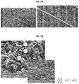
- FIG. 7A is a surface of a carbon composite heat treated for stabilization using a quaternary carbon composite composition according to an embodiment
- FIG. 7B is a cross-section of a carbon composite heat treated for stabilization using the quaternary carbon composite composition.
- FIG. 8 show a carbon heater made of a heating element using a composition according to an embodiment.
- a carbon composite composition of the present disclosure may include an inorganic powder, which may serve as a main component of a heating element to be used as or in a high temperature heater, and a binder that couples the inorganic powder particles with one another.
- silicon carbide (SiC), silicon oxide (SiO 2 ) and aluminum oxide (Al 2 O 3 ) may be used.
- Zirconium oxide (ZrO 2 ), boron nitride (BN) and molybdenum silicide (MoSi 2 ) may also be taken into consideration, but ZrO 2 and MoSi 2 have too low specific resistances to be used as a heater, and BN has too high a melting point, which may lead to an excessively high heat treatment temperature. For this reason, ZrO 2 , BN, and MoSi 2 may not be applied.
- the carbon composite composition may be characterized by including at least one of the above discussed inorganic powders. It may be necessary to include SiC since SiC, which has the lowest specific resistance among SiC, SiO 2 , and Al 2 O 3 inorganic powders, may stably maintain a specific resistance and an electric conductivity, which may be necessary properties for a heater. If the carbon composite composition is formed without SiC, the specific resistance may be too high to be used as a heater. SiO 2 and Al 2 O 3 in addition to SiC may be added as specific resistance controlling agents to control a specific resistance of a carbon heater since they have high specific resistances.
- SiC may be added in an amount of 50 to 75% based on the total weight of the composition for the following reasons.
- a content of SiC is less than 50%, a specific resistance of a carbon heater is excessively high and a thermal conductivity thereof is lowered, and thus disconnection may be likely to occur.
- the content of SiC exceeds 75%, the specific resistance of the carbon heater may be lowered so that it may be difficult to use such carbon heater as a heater.
- SiO 2 may be added at a maximum of 24% based on the total weight of the composition for the following reasons. When a content of SiO 2 exceeds 24%, thermal conductivity of the carbon heater is drastically lowered and thus a terminal disconnection may occur. In addition, when the manufactured carbon heater has an excessively high specific resistance due to a high specific resistance in SiO 2 , additional design changes, such as, for example, reducing a length of the heater or widening a cross-sectional area of the heater, may be required.
- a phenolic resin may perform functions of both a binder resin and a carbon raw material.
- Phenolic resin is one of the oldest synthetic resins, and it has excellent heat resistance and flame retardancy.
- Phenolic resin may be synthesized by a reaction of phenol and formaldehyde, and properties of phenolic resin greatly vary depending on acidity of a catalyst used therefor.
- a novolac resin is produced when the catalyst is an acid.
- Novolac resin may be obtained by reacting phenol and formaldehyde in a formaldehyde to phenol molar ratio of 0.5:1 to 1:1 in the presence of an acidic catalyst, such as, for example, sulfuric acid, hydrochloric acid, and oxalic acid. Under acidic catalysis, a condensation reaction may occur rapidly, and the novolac resin may have a structure in which a large number of phenol nuclei are linked by a methylene group.
- Novolac resin is a thermoplastic resin, so that the novolac resin has a property of not being cured without a curing agent.
- the novolac resin may be cured by condensation curing or thermal curing, normally mixed with hexamine and cured by heating.
- a resol resin may be obtained by reacting phenol and formaldehyde in a formaldehyde to phenol molar ratio of 1:1 to 3:1 in the presence of a basic catalyst, such as, for example, caustic soda or ammonia. Since a condensation reaction may occur more slowly than in an addition reaction, the resol resin may be produced as a compound of phenol alcohol having a relatively low molecular weight. That is, the resol resin has a structure in which many methylol groups are substituted in the phenol nucleus. Such resol resin has a property of being cured at a room temperature or at a moderate temperature without a curing agent. Thus, the novolac resin may be more suitable as the phenolic resin. Description thereon is set forth as follows.
- the carbon composite composition includes an inorganic powder to manufacture a carbon heater.
- an extrusion process is a process used in the technical field of using a resin.
- a curing reaction rapidly proceeds at a temperature and pressure at which the extrusion process is generally performed, and the carbon composite composition is cured before a carbon electrode is formed into a desired shape, so that extrusion molding may be impossible.
- the novolac resin according to embodiments may be added in an amount of 15 to 30% based on the total weight of the composition.
- a content of the novolac resin is less than 15%, the carbon composite composition obtained by performing the extrusion process is easily broken.
- a content of carbon in the finally produced carbon heater may be too low, so that the specific resistance of the carbon heater may become higher in comparison to a specification thereof.
- the content of the novolac resin exceeds 30%, the carbon composite composition may have poor stability in terms of a shape after an injection process is performed thereon, and the finally manufactured carbon heater may be more likely to have a dimensional defect.
- the carbon content in the carbon heater may become higher, whereby the specific resistance of the carbon heater may be lower in comparison to the specification thereof.
- the carbon composite composition may include a lubricant to reduce friction between the composition and a die during the extrusion process.
- a lubricant to reduce friction between the composition and a die during the extrusion process.
- a carbon heater it may be preferable to include carbon as a lubricant.
- Graphite, carbon black, and activated carbon may be used as the lubricant.
- graphite which is a widely used lubricant, has excellent lubrication properties during the extrusion process.
- the novolac resin may function as a curing agent and the graphite may function as a lubricant.
- a novolac resin is not cured by itself.
- a curing agent called “hexamine” is usually required for thermal curing.
- the carbon composite composition of the present disclosure is cured without the curing agent after the extrusion process is performed thereon when graphite is included in the carbon composite composition.
- the graphite may be added in an amount of 0.1 to 10% based on the total weight of the composition.
- a content of the graphite is less than 0.1%, the friction between the composition and the die increases during the extrusion process, and after the extrusion process, curing may be insufficient and the carbon composite may have poor stability in terms of shape, and thereby the finally manufactured carbon heater may be more likely to have a dimensional defect.
- the content of the graphite exceeds 10%, the curing reaction proceeds too quickly during the extrusion process, which makes processing such as extruding difficult, and the carbon content in the finally manufactured carbon heater becomes higher, whereby the specific resistance of the carbon heater may be lower in comparison to the specification thereof.
- a method for manufacturing a carbon heater using the carbon composite composition of the present disclosure is described.
- a method used to manufacture another functional material using the carbon composite composition may be applied to the carbon heater manufacturing method of the present disclosure.
- the manufacturing method may start with a process of mixing an inorganic power and a phenolic resin binder (S 100 ).
- a process of mixing an inorganic power and a phenolic resin binder S 100
- raw materials each having desired components and composition ranges may be sufficiently mixed for a desired or predetermined time using an apparatus, such as, for example, an attrition mill.
- the mixed raw materials may be thermally extruded using an extruder widely used in the field of polymer injection (S 200 ).
- An extrusion condition used for the present disclosure was a speed of 60 rpm at 100 to 200° C., but the extrusion condition is not limited thereto.
- the extrusion condition may be changed depending on components and composition ranges of the inorganic powder and the binder.
- the extruded carbon composite composition may be subjected to a stabilization heat treatment process at a high temperature (S 300 ).
- the stabilization heat treatment process is to cure the binder so that the extruded carbon composite composition may maintain its extruded shape.
- the stabilization heat treatment process was performed at 200 to 300° C. for 0.1 to 2 hours.
- the cured carbon composite composition may be subjected to a carbonization heat treatment process (S 400 ).
- the carbonization heat treatment process is to produce an active component of the carbon heater that is a final product, and may include a first step of out-gassing components, which volatilize a volatile component among the components constituting the carbon composite composition, and a second step of carbonizing the remaining components subsequent to the out-gassing step.
- the carbonization heat treatment process may be divided into two steps. First, a first carbonization heat treatment process may be performed at a relatively low temperature of 600-1,000° C. for 0.1 to 2 hours, and the first carbonization heat treatment process may volatilize components other than carbon among binder components, and other components other than carbon which may exist in impurities and the like included in components other than the binder components among components of the composition. A second carbonization heat treatment process may be performed, immediately after the first carbonization heat treatment process. The second carbonization heat treatment process may be performed at 1,200 to 1,400° C. for 0.5 to 3 hours, and may carbonize components of the carbon composite composition remaining after the first carbonization heat treatment process. In order to improve productivity, the first and second carbonization heat treatment processes may be integrated and operated in a single carbonization heat treatment process.
- a separate post-treatment process may be included to adjust or improve mechanical and/or electrical properties of the carbon heater subsequent to the carbonization heat treatment process.
- the carbon composite produced after the second heat treatment process may be combined with a connector and a sealing tube to manufacture the carbon heater that is the final product.
- a binary composition was prepared by mixing 1 type of inorganic powder selected from a group of SiC, SiO 2 , Al 2 O 3 and ZrO 2 shown in Table 1 above with a novolac resin as a binder.
- the prepared binary composition was mixed uniformly through a step of mixing raw materials, and then extruded.
- FIG. 4 and FIG. 5 show the carbon composite extruded and the carbon composite subjected to the stabilization heat treatment using the binary carbon composite composition, respectively.
- FIGS. 4 and 5 it was impossible to extrude the binary carbon composite composition into a desired shape due to extremely low mechanical stability after extrusion molding and molding are performed thereon ( FIG. 4 ), and the binary carbon composite composition had dimensional and surface defects, which may make it impossible to be used as a carbon heater even through the stabilization heat treatment was performed thereon after the curing agent is added ( FIG. 5 ).
- a ternary carbon composite composition was prepared by adding 23% of the novolac resin as a binder and 3% of the graphite as a lubricant to 74% of SiC among the inorganic power components shown in Table 1 above.
- the novolac resin used in this Example had a number average molecular weight in the range of 1,000 to 10,000, that is, a number of average molecular weight in the range of 3,000 to 7,000.
- the prepared ternary composition was mixed uniformly through the step of mixing raw materials and extruded, and subsequently was subjected to the stabilization heat treatment and the carbonization heat treatment processes, followed by being processed into a final carbon heater. Electrical properties of the final carbon heater were evaluated.
- FIGS. 6A and 6B show a surface and a cross-section of the ternary carbon composite after the stabilization heat treatment process is performed thereon.
- the carbon composite composed of the ternary composition has excellent macroscopic mechanical stability and almost no defect on the surface thereof. Also, SiC is very uniformly distributed by the binder even in the cross-sectional microstructure of the carbon composite without segregation, agglomeration, or macro voids.
- a carbon heater was manufactured using the ternary composition of Example 1, and the electrical properties thereof were evaluated. Electrical resistance of the carbon heater was measured to be about 4 to 5 ⁇ at an applied voltage of 115 V.
- Example 2 As Comparative Example 2 with respect to Example 1, another ternary carbon composite composition was prepared to include the inorganic powder substituted only with SiO 2 or Al 2 O 3 instead of SiC and the other components and composition ranges same as those of Example 1.
- the carbon composite composition of Comparative Example 2 was identified to have the same level of mechanical stability as that of Example 1. However, the electrical resistance of the carbon heater manufactured using the carbon composite composition of Comparative Example 2 was measured to be close to infinity at an applied voltage of 115 V. Thus, when only oxide is included as a base material of the carbon heater, it is very difficult to be used as a carbon heater.
- a quaternary carbon composite composition was prepared by adding a novolac resin as a binder and graphite as a lubricant to an inorganic powder which is based on SiC and further includes SiO 2 as a specific resistance controlling agent among the inorganic power components shown in Table 1 above.
- the prepared quaternary composition was mixed uniformly through the step of mixing raw materials and extruded, and subsequently was subjected to the stabilization heat treatment and the carbonization heat treatment processes, followed by being processed into a final carbon heater. Electrical properties of the final carbon heater were evaluated.
- FIGS. 7A and 7B show a surface and a cross-section of the quaternary carbon composite after the stabilization heat treatment process is performed thereon.
- the carbon composite composed of the ternary composition has excellent macroscopic mechanical stability and almost no defect on the surface thereof.
- SiC is uniformly distributed by the binder even in the cross-sectional microstructure of the carbon composite without segregation, agglomeration, or macro voids.
- SiC and SiO 2 were uniformly distributed without macroscopic/micro segregation.
- Table 2 shows electrical properties of a carbon heater made of ternary and quaternary carbon composites.
- PN, GP, SC and SO represent the novolac resin, graphite, SiC and SiO 2 , respectively.
- the more the content of SiO 2 increases the more the electrical resistance of the carbon heater increases, whereas the more the electrical conductivity of the carbon heater decreases.
- Such experimental results indicate that the electrical resistivity of the carbon heater made of the quaternary carbon composite may be controlled as needed, which means that the degree of freedom of electrical design may be greatly improved in comparison to the carbon heater made of the ternary carbon composite.
- the content of silicon oxide exceeded 24%, the thermal conductivity thereof was drastically lowered, and thus a terminal disconnection occurred.
- FIG. 8 shows a carbon heater product made of a heating element 11 using the carbon composite composition.
- the carbon heater may include the heating element 11 and a connector 14 to support the heating element 11 and supply power from outside. Also, the carbon heater may further include a tube 12 that encloses the heating element 14 and contains inert gas, a metal wire 15 that supplies electricity to the heating element 11 from outside, a metal piece 16 , and an outer electrode 17 .
- Embodiments disclosed herein provide a carbon composite composition for a new carbon heater which may not cause a dielectric breakdown or a spark even under a high voltage in a carbon heater. Embodiments disclosed herein also provide a carbon composite composition for a new carbon heater which may not cause plasma even under encapsulation gas and a high voltage in a carbon heater.
- a carbon composite composition may include a phenolic resin as a binder, a lubricant, and a base material determining a specific resistance of a resistance heating element at a high temperature.
- the base material may be silicon carbide (SiC). SiC may be included in an amount of 50 to 75 wt. % (hereafter referred to as “%”), based on the total weight of the composition.
- the composition may further include a specific resistance controlling agent.
- the specific resistance controlling agent may be silicon oxide (SiO 2 ). SiO 2 may be included in an amount of 24% or less, based on the total weight of the composition.
- the phenolic resin may be a novolac resin.
- the novolac resin may be included in an amount of 15 to 30%, based on the total weight of the composition.
- the lubricant may act as a curing agent.
- the lubricant may be graphite.
- the graphite may be included in an amount of 0.1 to 10%, based on the total weight of the composition.
- a carbon heater may include any one of the aforementioned compositions according to embodiments disclosed herein.
- the carbon composite composition may not generate a local concentration of voltage between filaments, which is a disadvantage inherent in a fiber shape, thereby preventing a dielectric breakdown or a spark from occurring.
- the carbon composite composition may fundamentally prevent plasma from occurring between filaments due to a local high voltage, and improve a decline in radiation efficiency because a shield member may not be necessary.
- the carbon composite composition has no restriction on a shape, which is an inherent property of a composition, and thereby it may be possible to easily manufacture a carbon heater of a desired shape necessary for an oven having various sizes and shapes.
- the carbon composite composition may control a specific resistance and an output of the carbon heater by changing constituent components and composition ranges of the composition, and thereby it may be possible to improve a degree of freedom of an electrical design of the carbon heater.
- the carbon composite composition may be excellent in resistance to surface oxidation or surface erosion, which may occur frequently at a high temperature since a surface area ratio may be relatively small in comparison to that of the conventional carbon fiber. Such property of the composition may make it possible to omit a post-treatment process, such as, for example, a surface coating, necessary for the conventional carbon fiber, thereby improving lead time and productivity.
- first, second, third, etc. may be used herein to describe various elements, components, regions, layers and/or sections, these elements, components, regions, layers and/or sections should not be limited by these terms. These terms are only used to distinguish one element, component, region, layer or section from another region, layer or section. Thus, a first element, component, region, layer or section could be termed a second element, component, region, layer or section without departing from the teachings of the present disclosure.
- spatially relative terms such as “lower”, “upper” and the like, may be used herein for ease of description to describe the relationship of one element or feature to another element(s) or feature(s) as illustrated in the figures. It will be understood that the spatially relative terms are intended to encompass different orientations of the device in use or operation, in addition to the orientation depicted in the figures. For example, if the device in the figures is turned over, elements described as “lower” relative to other elements or features would then be oriented “upper” relative the other elements or features. Thus, the exemplary term “lower” can encompass both an orientation of above and below. The device may be otherwise oriented (rotated 90 degrees or at other orientations) and the spatially relative descriptors used herein interpreted accordingly.
- Embodiments of the disclosure are described herein with reference to cross-section illustrations that are schematic illustrations of idealized embodiments (and intermediate structures) of the disclosure. As such, variations from the shapes of the illustrations as a result, for example, of manufacturing techniques and/or tolerances, are to be expected. Thus, embodiments of the disclosure should not be construed as limited to the particular shapes of regions illustrated herein but are to include deviations in shapes that result, for example, from manufacturing.
- any reference in this specification to “one embodiment,” “an embodiment,” “example embodiment,” etc. means that a particular feature, structure, or characteristic described in connection with the embodiment is included in at least one embodiment.
- the appearances of such phrases in various places in the specification are not necessarily all referring to the same embodiment.
Abstract
Description
| TABLE 1 |
| Properties of inorganic powders |
| Silicon | Silicon | Aluminium | Zirconium | Boron | Molybdenum | ||
| Carbide | Oxide | Oxide | Oxide | Nitride | Silicide | ||
| Melting point | 2,730° C. | 1,600° C. | 2,072° C. | 2,715° C. | 2,973° C. | 2,030° C. |
| (° C.) | ||||||
| Specific resistance | >108 | >1014 | >1014 | >104 | >1013 | 2 * 10−5 |
| (Ω · cm) | ||||||
| Thermal conductivity | 41 | 1.5 | 35 | 2.7 | 20 | 25 |
| (W/m · K) | ||||||
| TABLE 2 |
| Electrical properties of a carbon heater |
| PN23 | PN23 | PN23 | PN23 | |||
| GP03 | GP03 | GP03 | GP03 | PN23 | ||
| SC49 | SC56 | SC59 | SC62 | GP03 | ||
| SO25 | SO18 | SO15 | SO12 | SC74 | ||
| Applied voltage | 115 V | 115 V | 115 V | 115 V | 115 V |
| Length (m) | 22.00 | 23.00 | 22.30 | 20.00 | 20.00 |
| Electrical resistance (Ω) | 720.30 | 88.63 | 29.13 | 12.93 | 4~5 |
| Electrical conductivity | 0.21 | 1.18 | 6.25 | 12.50 | 46.00 |
| (S/cm) | |||||
Claims (14)
Applications Claiming Priority (2)
| Application Number | Priority Date | Filing Date | Title |
|---|---|---|---|
| KR1020170058076A KR102137032B1 (en) | 2017-05-10 | 2017-05-10 | A composition for carbon composite and a carbon heater manufactured by using the same |
| KR10-2017-0058076 | 2017-05-10 |
Publications (2)
| Publication Number | Publication Date |
|---|---|
| US20180327323A1 US20180327323A1 (en) | 2018-11-15 |
| US11097985B2 true US11097985B2 (en) | 2021-08-24 |
Family
ID=62152434
Family Applications (1)
| Application Number | Title | Priority Date | Filing Date |
|---|---|---|---|
| US15/975,348 Active 2038-09-28 US11097985B2 (en) | 2017-05-10 | 2018-05-09 | Carbon composite composition and carbon heater manufactured using the same |
Country Status (4)
| Country | Link |
|---|---|
| US (1) | US11097985B2 (en) |
| EP (1) | EP3405002A3 (en) |
| KR (1) | KR102137032B1 (en) |
| CN (1) | CN108863390B (en) |
Families Citing this family (3)
| Publication number | Priority date | Publication date | Assignee | Title |
|---|---|---|---|---|
| KR102137032B1 (en) | 2017-05-10 | 2020-07-23 | 엘지전자 주식회사 | A composition for carbon composite and a carbon heater manufactured by using the same |
| US20180338350A1 (en) * | 2017-05-19 | 2018-11-22 | Lg Electronics Inc. | Carbon heater |
| KR102004035B1 (en) * | 2017-05-26 | 2019-07-25 | 엘지전자 주식회사 | A carbon heating element |
Citations (42)
| Publication number | Priority date | Publication date | Assignee | Title |
|---|---|---|---|---|
| FR1300359A (en) | 1961-06-27 | 1962-08-03 | Norton Co | Electric heating bar |
| GB976468A (en) | 1960-03-02 | 1964-11-25 | Aktiebolaget Kanthal | |
| US3189778A (en) | 1962-01-29 | 1965-06-15 | Westinghouse Electric Corp | Lamp filament connection |
| US4525461A (en) * | 1983-12-14 | 1985-06-25 | Kennecott Corporation | Sintered silicon carbide/graphite/carbon composite ceramic body having ultrafine grain microstructure |
| WO1993014044A1 (en) | 1992-01-16 | 1993-07-22 | University Of Cincinnati | Electrical heating element, related composites, and composition and method for producing such products using dieless micropyretic synthesis |
| DE4413127C1 (en) | 1994-04-19 | 1995-10-05 | Forschungszentrum Juelich Gmbh | Process for the production of porous, flowable shaped bodies made of silicon carbide and shaped bodies |
| JPH10172738A (en) | 1996-12-04 | 1998-06-26 | Tokai Carbon Co Ltd | Glass like carbon heating element |
| JPH11354257A (en) | 1998-06-09 | 1999-12-24 | Matsushita Electric Ind Co Ltd | Carbon heating element and manufacture thereof |
| EP0971561A1 (en) | 1998-07-06 | 2000-01-12 | Electricite De France | Electrical heating resistance for electric furnace and manufacturing method for such a resistance |
| US20010055478A1 (en) | 2000-06-21 | 2001-12-27 | Joachim Scherzer | Infrared radiator |
| US20020142146A1 (en) | 1997-03-21 | 2002-10-03 | Daimlerchrysler Ag | Melted-infiltrated fiber-reinforced composite ceramic |
| US20020160902A1 (en) | 2001-03-08 | 2002-10-31 | Christoph Lesniak | Composite material based on silicon carbide and carbon, process for its production and its use |
| US6501056B1 (en) | 1998-04-28 | 2002-12-31 | E. Tec Corporation | Carbon heating element and method of manufacturing the same |
| US20030180538A1 (en) | 2002-03-19 | 2003-09-25 | Gray Paul E. | Melt-infiltrated pitch-pan preforms |
| EP1385357A2 (en) | 2002-07-23 | 2004-01-28 | Firbest Co. Ltd. | Far infrared radiation emitting material |
| US20040217111A1 (en) | 2003-04-29 | 2004-11-04 | Siegfried Grob | Infrared radiation source |
| US20050179152A1 (en) | 2001-12-31 | 2005-08-18 | Moritz Bauer | Process for producing shaped bodies comprising fiber-reinforced ceramic materials |
| CN1796334A (en) | 2004-12-27 | 2006-07-05 | 陈瑾惠 | Carbon/Carbon Composite material and mfg. method thereof |
| US20060272796A1 (en) | 2001-04-04 | 2006-12-07 | Asmussen Erick R | Flexible graphite flooring heat spreader |
| KR20070003836A (en) | 2003-12-26 | 2007-01-05 | 가부시키가이샤 브리지스톤 | Method for producing silicon carbide sintered body for heater |
| EP1741685A1 (en) | 2005-07-05 | 2007-01-10 | helsa-automotive GmbH & Co. KG | Porous beta-SiC containing shaped ceramic body and method of making it. |
| US20070034620A1 (en) | 2005-07-14 | 2007-02-15 | Lg Electronics Inc. | Heating body |
| CN1946655A (en) | 2004-04-23 | 2007-04-11 | 丰田自动车株式会社 | Composite carbon material having metal carbide particles dispersed therein and method for preparation thereof |
| US20070110413A1 (en) | 2003-11-20 | 2007-05-17 | Matsushita Electric Industrial Co., Ltd. | Infrared ray lamp and heating apparatus |
| US20080006620A1 (en) | 2005-07-14 | 2008-01-10 | Lee Young J | Heating unit and method of manufacturing the same |
| US20080217323A1 (en) | 2007-03-08 | 2008-09-11 | Seung Jo Baek | Heating device |
| CN101562914A (en) | 2008-04-17 | 2009-10-21 | 泰州市环能硅碳棒制造有限公司 | Production technology for cold end part of silicon carbide rod |
| CN101765253A (en) | 2010-02-02 | 2010-06-30 | 西安交通大学 | Method for preparing SiC heating element having long service life |
| US7769278B2 (en) | 2004-07-27 | 2010-08-03 | Lg Electronics Inc. | Carbon heater |
| KR20100117684A (en) | 2008-02-28 | 2010-11-03 | 바스프 에스이 | Graphite nanoplatelets and compositions |
| CN101880174A (en) | 2010-05-28 | 2010-11-10 | 上海麦戈士科贸有限公司 | Carbon/carbon composite density gradient thermal-insulation material |
| KR20110109697A (en) | 2010-03-31 | 2011-10-06 | 엘지전자 주식회사 | A method for coating oxidation protective layer for carbon/carbon composite, a carbon heater, and cooker |
| US20120052196A1 (en) * | 2010-08-24 | 2012-03-01 | Yuechu Ma | Monolithic graphitic castable refractory |
| JP2012051748A (en) | 2010-08-31 | 2012-03-15 | Tokyo Yogyo Co Ltd | Method for manufacturing conductive silicon carbide porous body |
| CN102558609A (en) | 2011-12-13 | 2012-07-11 | 金发科技股份有限公司 | Method for improving thermal conductivity of thermal conductive polymer |
| KR20130091382A (en) | 2012-02-08 | 2013-08-19 | (주)글로벌코센테크 | A heater of honeycomb structure using silicon carbide |
| CN104755554A (en) | 2012-11-02 | 2015-07-01 | 旭有机材工业株式会社 | Resin composition, carbon fiber-reinforced composite material precursor obtained using the resin composition, carbon fiber-reinforced material, and carbon fiber-reinforced carbon material |
| KR20150141382A (en) | 2014-06-10 | 2015-12-18 | 주식회사 유리테크 | SiC heater |
| JP2016067993A (en) | 2014-09-29 | 2016-05-09 | イビデン株式会社 | Manufacturing method of honeycomb filter |
| US20180327323A1 (en) | 2017-05-10 | 2018-11-15 | Lg Electronics Inc. | Carbon composite composition and carbon heater manufactured using the same |
| US20180343704A1 (en) | 2017-05-26 | 2018-11-29 | Lg Electronics Inc. | Carbon heating element and method for manufacturing a carbon heating element |
| US10542587B2 (en) | 2015-12-08 | 2020-01-21 | Temp4 Inc. | Heating elements of large sizes and of metallic tubular designs |
-
2017
- 2017-05-10 KR KR1020170058076A patent/KR102137032B1/en active IP Right Grant
-
2018
- 2018-05-09 US US15/975,348 patent/US11097985B2/en active Active
- 2018-05-10 CN CN201810443605.6A patent/CN108863390B/en active Active
- 2018-05-11 EP EP18171796.8A patent/EP3405002A3/en active Pending
Patent Citations (47)
| Publication number | Priority date | Publication date | Assignee | Title |
|---|---|---|---|---|
| GB976468A (en) | 1960-03-02 | 1964-11-25 | Aktiebolaget Kanthal | |
| FR1300359A (en) | 1961-06-27 | 1962-08-03 | Norton Co | Electric heating bar |
| US3189778A (en) | 1962-01-29 | 1965-06-15 | Westinghouse Electric Corp | Lamp filament connection |
| US4525461A (en) * | 1983-12-14 | 1985-06-25 | Kennecott Corporation | Sintered silicon carbide/graphite/carbon composite ceramic body having ultrafine grain microstructure |
| WO1993014044A1 (en) | 1992-01-16 | 1993-07-22 | University Of Cincinnati | Electrical heating element, related composites, and composition and method for producing such products using dieless micropyretic synthesis |
| US5420399A (en) | 1992-01-16 | 1995-05-30 | University Of Cincinnati | Electrical heating element, related composites, and composition and method for producing such products using dieless micropyretic synthesis |
| DE4413127C1 (en) | 1994-04-19 | 1995-10-05 | Forschungszentrum Juelich Gmbh | Process for the production of porous, flowable shaped bodies made of silicon carbide and shaped bodies |
| JPH10172738A (en) | 1996-12-04 | 1998-06-26 | Tokai Carbon Co Ltd | Glass like carbon heating element |
| US20020142146A1 (en) | 1997-03-21 | 2002-10-03 | Daimlerchrysler Ag | Melted-infiltrated fiber-reinforced composite ceramic |
| US6501056B1 (en) | 1998-04-28 | 2002-12-31 | E. Tec Corporation | Carbon heating element and method of manufacturing the same |
| JPH11354257A (en) | 1998-06-09 | 1999-12-24 | Matsushita Electric Ind Co Ltd | Carbon heating element and manufacture thereof |
| US6146550A (en) | 1998-07-06 | 2000-11-14 | Electricite De France-Service National | Electrical resistance heating element for an electric furnace and process for manufacturing such a resistance element |
| EP0971561A1 (en) | 1998-07-06 | 2000-01-12 | Electricite De France | Electrical heating resistance for electric furnace and manufacturing method for such a resistance |
| US20010055478A1 (en) | 2000-06-21 | 2001-12-27 | Joachim Scherzer | Infrared radiator |
| US20020160902A1 (en) | 2001-03-08 | 2002-10-31 | Christoph Lesniak | Composite material based on silicon carbide and carbon, process for its production and its use |
| US20060272796A1 (en) | 2001-04-04 | 2006-12-07 | Asmussen Erick R | Flexible graphite flooring heat spreader |
| US20050179152A1 (en) | 2001-12-31 | 2005-08-18 | Moritz Bauer | Process for producing shaped bodies comprising fiber-reinforced ceramic materials |
| US20030180538A1 (en) | 2002-03-19 | 2003-09-25 | Gray Paul E. | Melt-infiltrated pitch-pan preforms |
| EP1385357A2 (en) | 2002-07-23 | 2004-01-28 | Firbest Co. Ltd. | Far infrared radiation emitting material |
| US20040043687A1 (en) | 2002-07-23 | 2004-03-04 | Firbest Co., Ltd. | Far infrared radiation emitting material |
| US20040217111A1 (en) | 2003-04-29 | 2004-11-04 | Siegfried Grob | Infrared radiation source |
| US20070110413A1 (en) | 2003-11-20 | 2007-05-17 | Matsushita Electric Industrial Co., Ltd. | Infrared ray lamp and heating apparatus |
| KR20070003836A (en) | 2003-12-26 | 2007-01-05 | 가부시키가이샤 브리지스톤 | Method for producing silicon carbide sintered body for heater |
| US20070117722A1 (en) | 2003-12-26 | 2007-05-24 | Fumio Odaka | Method of producing silicon carbide sintered body for heater |
| CN1946655A (en) | 2004-04-23 | 2007-04-11 | 丰田自动车株式会社 | Composite carbon material having metal carbide particles dispersed therein and method for preparation thereof |
| US7769278B2 (en) | 2004-07-27 | 2010-08-03 | Lg Electronics Inc. | Carbon heater |
| CN1796334A (en) | 2004-12-27 | 2006-07-05 | 陈瑾惠 | Carbon/Carbon Composite material and mfg. method thereof |
| US20070032370A1 (en) | 2005-07-05 | 2007-02-08 | Lars Weisensel | Molded porous ceramic article containing beta-SiC and process for the production thereof |
| EP1741685A1 (en) | 2005-07-05 | 2007-01-10 | helsa-automotive GmbH & Co. KG | Porous beta-SiC containing shaped ceramic body and method of making it. |
| US20080006620A1 (en) | 2005-07-14 | 2008-01-10 | Lee Young J | Heating unit and method of manufacturing the same |
| US20070034620A1 (en) | 2005-07-14 | 2007-02-15 | Lg Electronics Inc. | Heating body |
| US20080217323A1 (en) | 2007-03-08 | 2008-09-11 | Seung Jo Baek | Heating device |
| KR20100117684A (en) | 2008-02-28 | 2010-11-03 | 바스프 에스이 | Graphite nanoplatelets and compositions |
| CN101562914A (en) | 2008-04-17 | 2009-10-21 | 泰州市环能硅碳棒制造有限公司 | Production technology for cold end part of silicon carbide rod |
| CN101765253A (en) | 2010-02-02 | 2010-06-30 | 西安交通大学 | Method for preparing SiC heating element having long service life |
| KR20110109697A (en) | 2010-03-31 | 2011-10-06 | 엘지전자 주식회사 | A method for coating oxidation protective layer for carbon/carbon composite, a carbon heater, and cooker |
| CN101880174A (en) | 2010-05-28 | 2010-11-10 | 上海麦戈士科贸有限公司 | Carbon/carbon composite density gradient thermal-insulation material |
| US20120052196A1 (en) * | 2010-08-24 | 2012-03-01 | Yuechu Ma | Monolithic graphitic castable refractory |
| JP2012051748A (en) | 2010-08-31 | 2012-03-15 | Tokyo Yogyo Co Ltd | Method for manufacturing conductive silicon carbide porous body |
| CN102558609A (en) | 2011-12-13 | 2012-07-11 | 金发科技股份有限公司 | Method for improving thermal conductivity of thermal conductive polymer |
| KR20130091382A (en) | 2012-02-08 | 2013-08-19 | (주)글로벌코센테크 | A heater of honeycomb structure using silicon carbide |
| CN104755554A (en) | 2012-11-02 | 2015-07-01 | 旭有机材工业株式会社 | Resin composition, carbon fiber-reinforced composite material precursor obtained using the resin composition, carbon fiber-reinforced material, and carbon fiber-reinforced carbon material |
| KR20150141382A (en) | 2014-06-10 | 2015-12-18 | 주식회사 유리테크 | SiC heater |
| JP2016067993A (en) | 2014-09-29 | 2016-05-09 | イビデン株式会社 | Manufacturing method of honeycomb filter |
| US10542587B2 (en) | 2015-12-08 | 2020-01-21 | Temp4 Inc. | Heating elements of large sizes and of metallic tubular designs |
| US20180327323A1 (en) | 2017-05-10 | 2018-11-15 | Lg Electronics Inc. | Carbon composite composition and carbon heater manufactured using the same |
| US20180343704A1 (en) | 2017-05-26 | 2018-11-29 | Lg Electronics Inc. | Carbon heating element and method for manufacturing a carbon heating element |
Non-Patent Citations (17)
| Title |
|---|
| Chen et al., "Macro/Micro Structure Dependence of Mechanical Strength of Low Temperature Sintered Silicon Carbide Ceramic Foams" Ceramics International, 38 (2012), pp. 5223-5229. (Full English Text). |
| Chinese Office Action dated Aug. 12, 2020 issued in Application No. 201810520993.3. |
| Chinese Office Action dated Oct. 27, 2020 issued in Application No. 201810443605.6. |
| European Office Action dated Sep. 5, 2019. |
| European Search Report dated Feb. 18, 2019 issued in Application No. 18174315.4. |
| European Search Report dated Nov. 30, 2018 issued in Application No. 18171796.8. |
| Gerhard Brauer, et al., HeT-SiC-05, International Topical Workshop on Heteroepitaxy of 3C-SiC on Silicon and its Application to Sensor Devices, Hotel Erbgericht Krippen, Germany, Apr. 26, 2005 to May 1, 2005 (ISSN 1437-322X). |
| Kim et al., "Effects of carbon and silicon on electrical, thermal, and mechanical properties of porous silicon carbide ceramics, "Mar. 2020, Ceramics International, pp. 15594, 15599-15601. (Year: 2020). |
| Korean Office Action dated Dec. 26, 2018 issued in Application No. 10-2017-0065488. |
| Korean Office Action dated Jun. 5, 2018 issued in Application No. 10-2017-0065488. |
| Korean Office Action dated May 29, 2018 issued in Application No. 10-2017-0058076. |
| Korean Office Action dated Nov. 14, 2018 issued in Application No. 10-2017-0058076. |
| Park et al., "Single-Crystal Growth Process of Silicon Carbide and Application Fields Thereof" Ceramist, vol. 13, Issue 6 (Dec. 2010), pp. 64-74. (English Abstract and Full Korean Text). |
| Polyak et al.; Science for Ceramic Production; High-Carbon Binders in Refractories and Corrosion-Resistant Ceramics Technology; vol. 55, No. 5-6, 1998. * |
| U.S. Appl. No. 15/986,107, filed May 22, 2018. |
| U.S. Final Office Action dated Feb. 12, 2021 issued in U.S. Appl. No. 15/986,107. |
| U.S. Office Action dated Aug. 10, 2020 issued in U.S. Appl. No. 15/986,107. |
Also Published As
| Publication number | Publication date |
|---|---|
| US20180327323A1 (en) | 2018-11-15 |
| KR20180123841A (en) | 2018-11-20 |
| EP3405002A2 (en) | 2018-11-21 |
| KR102137032B1 (en) | 2020-07-23 |
| CN108863390B (en) | 2022-02-22 |
| CN108863390A (en) | 2018-11-23 |
| EP3405002A3 (en) | 2019-01-02 |
Similar Documents
| Publication | Publication Date | Title |
|---|---|---|
| US11097985B2 (en) | Carbon composite composition and carbon heater manufactured using the same | |
| US11096249B2 (en) | Carbon heating element and method for manufacturing a carbon heating element | |
| KR102111551B1 (en) | Material for radiating Heat and Method of forming the same | |
| WO1998059526A1 (en) | Carbonaceous heating element and process for producing the same | |
| JP2012106888A (en) | Highly insulating silicon carbide powder and composition containing the same | |
| KR101470362B1 (en) | Heat dissipation pad using non-woven ceramic fabrics and manufacturing method thereof | |
| KR101537660B1 (en) | Thermal interface material comprising ceramic composite fiber and manufacturing method thereof | |
| Liu et al. | Microwave promoted rapid curing reaction of phenolic fibers | |
| US20140091080A1 (en) | Method for producing a resistance heating element, and resistance heating element | |
| KR20160063537A (en) | Expanded graphite, method for preparing the same and thermal conductive resin composition comprising the same | |
| KR102079363B1 (en) | A manufacturing method for carbon heater | |
| JP2022035196A (en) | Spherical ain particle and production method thereof, and composite material containing the same | |
| KR20210084007A (en) | Core-shell hybrid structured heat dissipating particles, and composites comprising the same | |
| KR20190056351A (en) | Process for the Preparation of Carbon Paper Containing Hybrid Materials of Carbon Microcoils-Carbon Nanocoils | |
| KR20200052841A (en) | MoCu HEAT DISSIPATION MATERIAL WITH CARBON PARTICLES AND PREPARING METHOD THEREOF | |
| KR102326570B1 (en) | Manufacturing Method Of Zinc Oxide With A High Specific Surface Area | |
| KR20190023112A (en) | Carbon Paper Having Hybrid Materials of Carbon Microcoils-Carbon Nanocoils | |
| JPH07257977A (en) | Preparation of cast ceramic | |
| KR102065524B1 (en) | SiOIC FIBER AND METAL DOPED SiOIC FIBER, MICROWAVE ABSORPTION AND HEATING ELEMENT INCLUDING THE SAME, AND METHOD FOR PREPARING THE SAME | |
| KR102126395B1 (en) | coating composition for plane heater and plane heater prepared therefrom | |
| JP3198120B2 (en) | Method for producing glassy carbon plate | |
| JP4071691B2 (en) | Manufacturing method of heating element mainly composed of MoSi2 and having excellent thermal shock resistance, and heating element | |
| JPH11242984A (en) | Carbonic heating element | |
| JPH11242986A (en) | Carbonic heating element | |
| CN107880381A (en) | A kind of high-performance sheathing material of magnetic drive pump electricity container |
Legal Events
| Date | Code | Title | Description |
|---|---|---|---|
| AS | Assignment |
Owner name: INDUSTRY FOUNDATION OF CHONNAM NATIONAL UNIVERSITY, KOREA, REPUBLIC OF Free format text: ASSIGNMENT OF ASSIGNORS INTEREST;ASSIGNORS:LEE, YOUNGJUN;YANG, KAP SEUNG;KIM, SANG WAN;SIGNING DATES FROM 20180424 TO 20180508;REEL/FRAME:045756/0601 Owner name: LG ELECTRONICS INC., KOREA, REPUBLIC OF Free format text: ASSIGNMENT OF ASSIGNORS INTEREST;ASSIGNORS:LEE, YOUNGJUN;YANG, KAP SEUNG;KIM, SANG WAN;SIGNING DATES FROM 20180424 TO 20180508;REEL/FRAME:045756/0601 Owner name: INDUSTRY FOUNDATION OF CHONNAM NATIONAL UNIVERSITY Free format text: ASSIGNMENT OF ASSIGNORS INTEREST;ASSIGNORS:LEE, YOUNGJUN;YANG, KAP SEUNG;KIM, SANG WAN;SIGNING DATES FROM 20180424 TO 20180508;REEL/FRAME:045756/0601 |
|
| FEPP | Fee payment procedure |
Free format text: ENTITY STATUS SET TO UNDISCOUNTED (ORIGINAL EVENT CODE: BIG.); ENTITY STATUS OF PATENT OWNER: LARGE ENTITY |
|
| STPP | Information on status: patent application and granting procedure in general |
Free format text: DOCKETED NEW CASE - READY FOR EXAMINATION |
|
| STPP | Information on status: patent application and granting procedure in general |
Free format text: NON FINAL ACTION MAILED |
|
| STPP | Information on status: patent application and granting procedure in general |
Free format text: RESPONSE TO NON-FINAL OFFICE ACTION ENTERED AND FORWARDED TO EXAMINER |
|
| STPP | Information on status: patent application and granting procedure in general |
Free format text: NOTICE OF ALLOWANCE MAILED -- APPLICATION RECEIVED IN OFFICE OF PUBLICATIONS |
|
| STPP | Information on status: patent application and granting procedure in general |
Free format text: AWAITING TC RESP., ISSUE FEE NOT PAID Free format text: NOTICE OF ALLOWANCE MAILED -- APPLICATION RECEIVED IN OFFICE OF PUBLICATIONS |
|
| STPP | Information on status: patent application and granting procedure in general |
Free format text: PUBLICATIONS -- ISSUE FEE PAYMENT RECEIVED |
|
| STPP | Information on status: patent application and granting procedure in general |
Free format text: PUBLICATIONS -- ISSUE FEE PAYMENT VERIFIED |
|
| STCF | Information on status: patent grant |
Free format text: PATENTED CASE |