US11090107B2 - Ablation medical devices - Google Patents
Ablation medical devices Download PDFInfo
- Publication number
- US11090107B2 US11090107B2 US14/796,711 US201514796711A US11090107B2 US 11090107 B2 US11090107 B2 US 11090107B2 US 201514796711 A US201514796711 A US 201514796711A US 11090107 B2 US11090107 B2 US 11090107B2
- Authority
- US
- United States
- Prior art keywords
- ablation
- tines
- substrate
- flexible circuit
- tubular member
- Prior art date
- Legal status (The legal status is an assumption and is not a legal conclusion. Google has not performed a legal analysis and makes no representation as to the accuracy of the status listed.)
- Active, expires
Links
- 238000002679 ablation Methods 0.000 title claims abstract description 102
- 239000000758 substrate Substances 0.000 claims abstract description 63
- 238000003491 array Methods 0.000 claims description 13
- 239000004020 conductor Substances 0.000 claims description 6
- 238000000034 method Methods 0.000 abstract description 13
- 229910001000 nickel titanium Inorganic materials 0.000 description 25
- 239000000463 material Substances 0.000 description 21
- HLXZNVUGXRDIFK-UHFFFAOYSA-N nickel titanium Chemical compound [Ti].[Ti].[Ti].[Ti].[Ti].[Ti].[Ti].[Ti].[Ti].[Ti].[Ti].[Ni].[Ni].[Ni].[Ni].[Ni].[Ni].[Ni].[Ni].[Ni].[Ni].[Ni].[Ni].[Ni].[Ni] HLXZNVUGXRDIFK-UHFFFAOYSA-N 0.000 description 16
- -1 HASTELLOY® C276® Chemical compound 0.000 description 11
- 238000000576 coating method Methods 0.000 description 10
- 230000003902 lesion Effects 0.000 description 9
- 229920000642 polymer Polymers 0.000 description 9
- 229910001182 Mo alloy Inorganic materials 0.000 description 7
- 229910045601 alloy Inorganic materials 0.000 description 7
- 239000000956 alloy Substances 0.000 description 7
- 238000004519 manufacturing process Methods 0.000 description 6
- 239000011248 coating agent Substances 0.000 description 5
- 239000000203 mixture Substances 0.000 description 5
- PXHVJJICTQNCMI-UHFFFAOYSA-N Nickel Chemical compound [Ni] PXHVJJICTQNCMI-UHFFFAOYSA-N 0.000 description 4
- 230000003213 activating effect Effects 0.000 description 4
- 229910000856 hastalloy Inorganic materials 0.000 description 4
- BASFCYQUMIYNBI-UHFFFAOYSA-N platinum Chemical compound [Pt] BASFCYQUMIYNBI-UHFFFAOYSA-N 0.000 description 4
- 229920001343 polytetrafluoroethylene Polymers 0.000 description 4
- 239000004810 polytetrafluoroethylene Substances 0.000 description 4
- 239000010935 stainless steel Substances 0.000 description 4
- 229910001220 stainless steel Inorganic materials 0.000 description 4
- RTZKZFJDLAIYFH-UHFFFAOYSA-N Diethyl ether Chemical compound CCOCC RTZKZFJDLAIYFH-UHFFFAOYSA-N 0.000 description 3
- 229920000106 Liquid crystal polymer Polymers 0.000 description 3
- 239000004977 Liquid-crystal polymers (LCPs) Substances 0.000 description 3
- 239000004952 Polyamide Substances 0.000 description 3
- 229920002614 Polyether block amide Polymers 0.000 description 3
- 239000004642 Polyimide Substances 0.000 description 3
- 239000004721 Polyphenylene oxide Substances 0.000 description 3
- 238000001125 extrusion Methods 0.000 description 3
- 230000006870 function Effects 0.000 description 3
- 229920001903 high density polyethylene Polymers 0.000 description 3
- 239000004700 high-density polyethylene Substances 0.000 description 3
- 238000002595 magnetic resonance imaging Methods 0.000 description 3
- 229910052751 metal Inorganic materials 0.000 description 3
- 239000002184 metal Substances 0.000 description 3
- 229920002647 polyamide Polymers 0.000 description 3
- 229920001721 polyimide Polymers 0.000 description 3
- 238000007674 radiofrequency ablation Methods 0.000 description 3
- RYGMFSIKBFXOCR-UHFFFAOYSA-N Copper Chemical compound [Cu] RYGMFSIKBFXOCR-UHFFFAOYSA-N 0.000 description 2
- 229910000881 Cu alloy Inorganic materials 0.000 description 2
- 239000004812 Fluorinated ethylene propylene Substances 0.000 description 2
- 229920000339 Marlex Polymers 0.000 description 2
- KDLHZDBZIXYQEI-UHFFFAOYSA-N Palladium Chemical compound [Pd] KDLHZDBZIXYQEI-UHFFFAOYSA-N 0.000 description 2
- 239000004696 Poly ether ether ketone Substances 0.000 description 2
- 239000004697 Polyetherimide Substances 0.000 description 2
- 239000004698 Polyethylene Substances 0.000 description 2
- 239000004734 Polyphenylene sulfide Substances 0.000 description 2
- 239000004743 Polypropylene Substances 0.000 description 2
- RTAQQCXQSZGOHL-UHFFFAOYSA-N Titanium Chemical compound [Ti] RTAQQCXQSZGOHL-UHFFFAOYSA-N 0.000 description 2
- 229910001080 W alloy Inorganic materials 0.000 description 2
- MTHLBYMFGWSRME-UHFFFAOYSA-N [Cr].[Co].[Mo] Chemical compound [Cr].[Co].[Mo] MTHLBYMFGWSRME-UHFFFAOYSA-N 0.000 description 2
- HZEWFHLRYVTOIW-UHFFFAOYSA-N [Ti].[Ni] Chemical compound [Ti].[Ni] HZEWFHLRYVTOIW-UHFFFAOYSA-N 0.000 description 2
- 238000004458 analytical method Methods 0.000 description 2
- 229910001566 austenite Inorganic materials 0.000 description 2
- 238000005452 bending Methods 0.000 description 2
- 238000004364 calculation method Methods 0.000 description 2
- 239000000788 chromium alloy Substances 0.000 description 2
- PRQRQKBNBXPISG-UHFFFAOYSA-N chromium cobalt molybdenum nickel Chemical compound [Cr].[Co].[Ni].[Mo] PRQRQKBNBXPISG-UHFFFAOYSA-N 0.000 description 2
- 229920001577 copolymer Polymers 0.000 description 2
- 229910052802 copper Inorganic materials 0.000 description 2
- 239000010949 copper Substances 0.000 description 2
- YOCUPQPZWBBYIX-UHFFFAOYSA-N copper nickel Chemical compound [Ni].[Cu] YOCUPQPZWBBYIX-UHFFFAOYSA-N 0.000 description 2
- 230000008878 coupling Effects 0.000 description 2
- 238000010168 coupling process Methods 0.000 description 2
- 238000005859 coupling reaction Methods 0.000 description 2
- 238000000113 differential scanning calorimetry Methods 0.000 description 2
- 229910000701 elgiloys (Co-Cr-Ni Alloy) Inorganic materials 0.000 description 2
- 150000002148 esters Chemical class 0.000 description 2
- 229920000840 ethylene tetrafluoroethylene copolymer Polymers 0.000 description 2
- 239000000945 filler Substances 0.000 description 2
- PCHJSUWPFVWCPO-UHFFFAOYSA-N gold Chemical compound [Au] PCHJSUWPFVWCPO-UHFFFAOYSA-N 0.000 description 2
- 229910052737 gold Inorganic materials 0.000 description 2
- 239000010931 gold Substances 0.000 description 2
- 238000010438 heat treatment Methods 0.000 description 2
- 229920001477 hydrophilic polymer Polymers 0.000 description 2
- 229910000734 martensite Inorganic materials 0.000 description 2
- 229910001092 metal group alloy Inorganic materials 0.000 description 2
- 238000012986 modification Methods 0.000 description 2
- 230000004048 modification Effects 0.000 description 2
- DDTIGTPWGISMKL-UHFFFAOYSA-N molybdenum nickel Chemical compound [Ni].[Mo] DDTIGTPWGISMKL-UHFFFAOYSA-N 0.000 description 2
- 229910052759 nickel Inorganic materials 0.000 description 2
- 229920009441 perflouroethylene propylene Polymers 0.000 description 2
- 229910052697 platinum Inorganic materials 0.000 description 2
- 229920001200 poly(ethylene-vinyl acetate) Polymers 0.000 description 2
- 229920001707 polybutylene terephthalate Polymers 0.000 description 2
- 229920000728 polyester Polymers 0.000 description 2
- 229920002530 polyetherether ketone Polymers 0.000 description 2
- 229920001601 polyetherimide Polymers 0.000 description 2
- 229920000573 polyethylene Polymers 0.000 description 2
- 229920000139 polyethylene terephthalate Polymers 0.000 description 2
- 239000005020 polyethylene terephthalate Substances 0.000 description 2
- 229920006324 polyoxymethylene Polymers 0.000 description 2
- 229920006380 polyphenylene oxide Polymers 0.000 description 2
- 229920000069 polyphenylene sulfide Polymers 0.000 description 2
- 229920001155 polypropylene Polymers 0.000 description 2
- 229920001296 polysiloxane Polymers 0.000 description 2
- 229920002635 polyurethane Polymers 0.000 description 2
- 239000004814 polyurethane Substances 0.000 description 2
- 230000001681 protective effect Effects 0.000 description 2
- 230000009467 reduction Effects 0.000 description 2
- 239000007787 solid Substances 0.000 description 2
- 238000012358 sourcing Methods 0.000 description 2
- 239000010936 titanium Substances 0.000 description 2
- 229910052719 titanium Inorganic materials 0.000 description 2
- KHXKESCWFMPTFT-UHFFFAOYSA-N 1,1,1,2,2,3,3-heptafluoro-3-(1,2,2-trifluoroethenoxy)propane Chemical compound FC(F)=C(F)OC(F)(F)C(F)(F)C(F)(F)F KHXKESCWFMPTFT-UHFFFAOYSA-N 0.000 description 1
- 229910000531 Co alloy Inorganic materials 0.000 description 1
- 229920004943 Delrin® Polymers 0.000 description 1
- 229920006055 Durethan® Polymers 0.000 description 1
- 239000004593 Epoxy Substances 0.000 description 1
- 229920000219 Ethylene vinyl alcohol Polymers 0.000 description 1
- 229910000640 Fe alloy Inorganic materials 0.000 description 1
- 229920003620 Grilon® Polymers 0.000 description 1
- DGAQECJNVWCQMB-PUAWFVPOSA-M Ilexoside XXIX Chemical compound C[C@@H]1CC[C@@]2(CC[C@@]3(C(=CC[C@H]4[C@]3(CC[C@@H]5[C@@]4(CC[C@@H](C5(C)C)OS(=O)(=O)[O-])C)C)[C@@H]2[C@]1(C)O)C)C(=O)O[C@H]6[C@@H]([C@H]([C@@H]([C@H](O6)CO)O)O)O.[Na+] DGAQECJNVWCQMB-PUAWFVPOSA-M 0.000 description 1
- 229920000271 Kevlar® Polymers 0.000 description 1
- JHWNWJKBPDFINM-UHFFFAOYSA-N Laurolactam Chemical compound O=C1CCCCCCCCCCCN1 JHWNWJKBPDFINM-UHFFFAOYSA-N 0.000 description 1
- 229910001209 Low-carbon steel Inorganic materials 0.000 description 1
- 229910000792 Monel Inorganic materials 0.000 description 1
- 206010028980 Neoplasm Diseases 0.000 description 1
- 229910000990 Ni alloy Inorganic materials 0.000 description 1
- 239000004677 Nylon Substances 0.000 description 1
- 229920000299 Nylon 12 Polymers 0.000 description 1
- 229930040373 Paraformaldehyde Natural products 0.000 description 1
- 229920000265 Polyparaphenylene Polymers 0.000 description 1
- 239000004793 Polystyrene Substances 0.000 description 1
- QXZUUHYBWMWJHK-UHFFFAOYSA-N [Co].[Ni] Chemical compound [Co].[Ni] QXZUUHYBWMWJHK-UHFFFAOYSA-N 0.000 description 1
- 229920000615 alginic acid Polymers 0.000 description 1
- 235000010443 alginic acid Nutrition 0.000 description 1
- 229920000249 biocompatible polymer Polymers 0.000 description 1
- 230000036760 body temperature Effects 0.000 description 1
- 150000001720 carbohydrates Chemical class 0.000 description 1
- 239000000919 ceramic Substances 0.000 description 1
- 230000008859 change Effects 0.000 description 1
- OGSYQYXYGXIQFH-UHFFFAOYSA-N chromium molybdenum nickel Chemical compound [Cr].[Ni].[Mo] OGSYQYXYGXIQFH-UHFFFAOYSA-N 0.000 description 1
- 239000002131 composite material Substances 0.000 description 1
- 150000001875 compounds Chemical class 0.000 description 1
- 230000006735 deficit Effects 0.000 description 1
- 230000000694 effects Effects 0.000 description 1
- 239000013013 elastic material Substances 0.000 description 1
- 229920001971 elastomer Polymers 0.000 description 1
- 239000000806 elastomer Substances 0.000 description 1
- 229920006351 engineering plastic Polymers 0.000 description 1
- JBKVHLHDHHXQEQ-UHFFFAOYSA-N epsilon-caprolactam Chemical compound O=C1CCCCCN1 JBKVHLHDHHXQEQ-UHFFFAOYSA-N 0.000 description 1
- QHSJIZLJUFMIFP-UHFFFAOYSA-N ethene;1,1,2,2-tetrafluoroethene Chemical group C=C.FC(F)=C(F)F QHSJIZLJUFMIFP-UHFFFAOYSA-N 0.000 description 1
- HQQADJVZYDDRJT-UHFFFAOYSA-N ethene;prop-1-ene Chemical group C=C.CC=C HQQADJVZYDDRJT-UHFFFAOYSA-N 0.000 description 1
- 150000002170 ethers Chemical class 0.000 description 1
- 239000005038 ethylene vinyl acetate Substances 0.000 description 1
- 239000004715 ethylene vinyl alcohol Substances 0.000 description 1
- 239000003302 ferromagnetic material Substances 0.000 description 1
- 238000010304 firing Methods 0.000 description 1
- 229920002313 fluoropolymer Polymers 0.000 description 1
- 239000004811 fluoropolymer Substances 0.000 description 1
- 238000002594 fluoroscopy Methods 0.000 description 1
- RZXDTJIXPSCHCI-UHFFFAOYSA-N hexa-1,5-diene-2,5-diol Chemical compound OC(=C)CCC(O)=C RZXDTJIXPSCHCI-UHFFFAOYSA-N 0.000 description 1
- 230000002209 hydrophobic effect Effects 0.000 description 1
- 125000002768 hydroxyalkyl group Chemical group 0.000 description 1
- 238000003384 imaging method Methods 0.000 description 1
- 229910001026 inconel Inorganic materials 0.000 description 1
- 229920000554 ionomer Polymers 0.000 description 1
- UGKDIUIOSMUOAW-UHFFFAOYSA-N iron nickel Chemical compound [Fe].[Ni] UGKDIUIOSMUOAW-UHFFFAOYSA-N 0.000 description 1
- 229920000092 linear low density polyethylene Polymers 0.000 description 1
- 239000004707 linear low-density polyethylene Substances 0.000 description 1
- 229920001684 low density polyethylene Polymers 0.000 description 1
- 239000004702 low-density polyethylene Substances 0.000 description 1
- 239000003550 marker Substances 0.000 description 1
- 239000002905 metal composite material Substances 0.000 description 1
- 150000002739 metals Chemical class 0.000 description 1
- MOWMLACGTDMJRV-UHFFFAOYSA-N nickel tungsten Chemical compound [Ni].[W] MOWMLACGTDMJRV-UHFFFAOYSA-N 0.000 description 1
- 229910000623 nickel–chromium alloy Inorganic materials 0.000 description 1
- 229920001778 nylon Polymers 0.000 description 1
- 229910052763 palladium Inorganic materials 0.000 description 1
- VPRUMANMDWQMNF-UHFFFAOYSA-N phenylethane boronic acid Chemical compound OB(O)CCC1=CC=CC=C1 VPRUMANMDWQMNF-UHFFFAOYSA-N 0.000 description 1
- XNGIFLGASWRNHJ-UHFFFAOYSA-L phthalate(2-) Chemical compound [O-]C(=O)C1=CC=CC=C1C([O-])=O XNGIFLGASWRNHJ-UHFFFAOYSA-L 0.000 description 1
- 229920003023 plastic Polymers 0.000 description 1
- 239000004033 plastic Substances 0.000 description 1
- 229920002492 poly(sulfone) Polymers 0.000 description 1
- 229920000412 polyarylene Polymers 0.000 description 1
- 239000004417 polycarbonate Substances 0.000 description 1
- 229920000515 polycarbonate Polymers 0.000 description 1
- 229920000570 polyether Polymers 0.000 description 1
- 239000011112 polyethylene naphthalate Substances 0.000 description 1
- 239000002861 polymer material Substances 0.000 description 1
- 229920000098 polyolefin Polymers 0.000 description 1
- 229920002223 polystyrene Polymers 0.000 description 1
- 229920002215 polytrimethylene terephthalate Polymers 0.000 description 1
- 229920002451 polyvinyl alcohol Polymers 0.000 description 1
- 235000019422 polyvinyl alcohol Nutrition 0.000 description 1
- 239000004800 polyvinyl chloride Substances 0.000 description 1
- 239000005033 polyvinylidene chloride Substances 0.000 description 1
- 230000008569 process Effects 0.000 description 1
- 229910052708 sodium Inorganic materials 0.000 description 1
- 239000011734 sodium Substances 0.000 description 1
- 229910052715 tantalum Inorganic materials 0.000 description 1
- GUVRBAGPIYLISA-UHFFFAOYSA-N tantalum atom Chemical compound [Ta] GUVRBAGPIYLISA-UHFFFAOYSA-N 0.000 description 1
- MHSKRLJMQQNJNC-UHFFFAOYSA-N terephthalamide Chemical compound NC(=O)C1=CC=C(C(N)=O)C=C1 MHSKRLJMQQNJNC-UHFFFAOYSA-N 0.000 description 1
- 125000000383 tetramethylene group Chemical group [H]C([H])([*:1])C([H])([H])C([H])([H])C([H])([H])[*:2] 0.000 description 1
- 238000002076 thermal analysis method Methods 0.000 description 1
- WFKWXMTUELFFGS-UHFFFAOYSA-N tungsten Chemical compound [W] WFKWXMTUELFFGS-UHFFFAOYSA-N 0.000 description 1
- 229910052721 tungsten Inorganic materials 0.000 description 1
- 239000010937 tungsten Substances 0.000 description 1
- 238000012800 visualization Methods 0.000 description 1
- XLYOFNOQVPJJNP-UHFFFAOYSA-N water Substances O XLYOFNOQVPJJNP-UHFFFAOYSA-N 0.000 description 1
Images


Classifications
-
- A—HUMAN NECESSITIES
- A61—MEDICAL OR VETERINARY SCIENCE; HYGIENE
- A61B—DIAGNOSIS; SURGERY; IDENTIFICATION
- A61B18/00—Surgical instruments, devices or methods for transferring non-mechanical forms of energy to or from the body
- A61B18/04—Surgical instruments, devices or methods for transferring non-mechanical forms of energy to or from the body by heating
- A61B18/12—Surgical instruments, devices or methods for transferring non-mechanical forms of energy to or from the body by heating by passing a current through the tissue to be heated, e.g. high-frequency current
- A61B18/14—Probes or electrodes therefor
- A61B18/1492—Probes or electrodes therefor having a flexible, catheter-like structure, e.g. for heart ablation
-
- A—HUMAN NECESSITIES
- A61—MEDICAL OR VETERINARY SCIENCE; HYGIENE
- A61B—DIAGNOSIS; SURGERY; IDENTIFICATION
- A61B18/00—Surgical instruments, devices or methods for transferring non-mechanical forms of energy to or from the body
- A61B18/04—Surgical instruments, devices or methods for transferring non-mechanical forms of energy to or from the body by heating
- A61B18/12—Surgical instruments, devices or methods for transferring non-mechanical forms of energy to or from the body by heating by passing a current through the tissue to be heated, e.g. high-frequency current
- A61B18/14—Probes or electrodes therefor
-
- A—HUMAN NECESSITIES
- A61—MEDICAL OR VETERINARY SCIENCE; HYGIENE
- A61B—DIAGNOSIS; SURGERY; IDENTIFICATION
- A61B17/00—Surgical instruments, devices or methods, e.g. tourniquets
- A61B2017/00526—Methods of manufacturing
-
- A—HUMAN NECESSITIES
- A61—MEDICAL OR VETERINARY SCIENCE; HYGIENE
- A61B—DIAGNOSIS; SURGERY; IDENTIFICATION
- A61B18/00—Surgical instruments, devices or methods for transferring non-mechanical forms of energy to or from the body
- A61B2018/00053—Mechanical features of the instrument of device
-
- A—HUMAN NECESSITIES
- A61—MEDICAL OR VETERINARY SCIENCE; HYGIENE
- A61B—DIAGNOSIS; SURGERY; IDENTIFICATION
- A61B18/00—Surgical instruments, devices or methods for transferring non-mechanical forms of energy to or from the body
- A61B2018/00053—Mechanical features of the instrument of device
- A61B2018/0016—Energy applicators arranged in a two- or three dimensional array
-
- A—HUMAN NECESSITIES
- A61—MEDICAL OR VETERINARY SCIENCE; HYGIENE
- A61B—DIAGNOSIS; SURGERY; IDENTIFICATION
- A61B18/00—Surgical instruments, devices or methods for transferring non-mechanical forms of energy to or from the body
- A61B2018/00571—Surgical instruments, devices or methods for transferring non-mechanical forms of energy to or from the body for achieving a particular surgical effect
- A61B2018/00577—Ablation
-
- A—HUMAN NECESSITIES
- A61—MEDICAL OR VETERINARY SCIENCE; HYGIENE
- A61B—DIAGNOSIS; SURGERY; IDENTIFICATION
- A61B18/00—Surgical instruments, devices or methods for transferring non-mechanical forms of energy to or from the body
- A61B2018/00636—Sensing and controlling the application of energy
- A61B2018/00642—Sensing and controlling the application of energy with feedback, i.e. closed loop control
-
- A—HUMAN NECESSITIES
- A61—MEDICAL OR VETERINARY SCIENCE; HYGIENE
- A61B—DIAGNOSIS; SURGERY; IDENTIFICATION
- A61B18/00—Surgical instruments, devices or methods for transferring non-mechanical forms of energy to or from the body
- A61B2018/00636—Sensing and controlling the application of energy
- A61B2018/00696—Controlled or regulated parameters
- A61B2018/00702—Power or energy
-
- A—HUMAN NECESSITIES
- A61—MEDICAL OR VETERINARY SCIENCE; HYGIENE
- A61B—DIAGNOSIS; SURGERY; IDENTIFICATION
- A61B18/00—Surgical instruments, devices or methods for transferring non-mechanical forms of energy to or from the body
- A61B2018/00636—Sensing and controlling the application of energy
- A61B2018/00773—Sensed parameters
- A61B2018/00791—Temperature
- A61B2018/00797—Temperature measured by multiple temperature sensors
-
- A—HUMAN NECESSITIES
- A61—MEDICAL OR VETERINARY SCIENCE; HYGIENE
- A61B—DIAGNOSIS; SURGERY; IDENTIFICATION
- A61B18/00—Surgical instruments, devices or methods for transferring non-mechanical forms of energy to or from the body
- A61B18/04—Surgical instruments, devices or methods for transferring non-mechanical forms of energy to or from the body by heating
- A61B18/12—Surgical instruments, devices or methods for transferring non-mechanical forms of energy to or from the body by heating by passing a current through the tissue to be heated, e.g. high-frequency current
- A61B18/14—Probes or electrodes therefor
- A61B2018/1405—Electrodes having a specific shape
- A61B2018/1425—Needle
- A61B2018/143—Needle multiple needles
-
- A—HUMAN NECESSITIES
- A61—MEDICAL OR VETERINARY SCIENCE; HYGIENE
- A61B—DIAGNOSIS; SURGERY; IDENTIFICATION
- A61B18/00—Surgical instruments, devices or methods for transferring non-mechanical forms of energy to or from the body
- A61B18/04—Surgical instruments, devices or methods for transferring non-mechanical forms of energy to or from the body by heating
- A61B18/12—Surgical instruments, devices or methods for transferring non-mechanical forms of energy to or from the body by heating by passing a current through the tissue to be heated, e.g. high-frequency current
- A61B18/14—Probes or electrodes therefor
- A61B2018/1475—Electrodes retractable in or deployable from a housing
-
- A—HUMAN NECESSITIES
- A61—MEDICAL OR VETERINARY SCIENCE; HYGIENE
- A61B—DIAGNOSIS; SURGERY; IDENTIFICATION
- A61B2562/00—Details of sensors; Constructional details of sensor housings or probes; Accessories for sensors
- A61B2562/16—Details of sensor housings or probes; Details of structural supports for sensors
- A61B2562/164—Details of sensor housings or probes; Details of structural supports for sensors the sensor is mounted in or on a conformable substrate or carrier
Definitions
- the present disclosure pertains to medical devices, and methods for manufacturing medical devices. More particularly, the present disclosure pertains to medical devices for ablating tissue.
- intracorporeal medical devices have been developed for medical use, for example, intravascular use. Some of these devices include guidewires, catheters, and the like. These devices are manufactured by any one of a variety of different manufacturing methods and may be used according to any one of a variety of methods. Of the known medical devices and methods, each has certain advantages and disadvantages. There is an ongoing need to provide alternative medical devices as well as alternative methods for manufacturing and using medical devices.
- An embodiment medical device may include an ablation system.
- the ablation system includes an elongate shaft having a distal region.
- a plurality of ablation tines is disposed at the distal region.
- Each of the ablation tines includes a tubular member having a flexible circuit disposed therein.
- the flexible circuit includes a substrate, one or more electrodes coupled to the substrate, and a temperature sensor coupled to the substrate and positioned adjacent to the one or more electrodes.
- the plurality of ablation tines includes a first ablation tine and a second ablation tine.
- a pair of bipolar electrodes is defined by a first electrode disposed at the first ablation tine and a second electrode disposed at the second ablation tine.
- the plurality of ablation tines includes a distal array of ablation tines and a proximal array of ablation tines.
- the distal array of ablation tines is circumferentially offset from the proximal array of ablation tines.
- the flexible circuit includes a first trace disposed along a first side of the substrate, the first trace being coupled to the temperature sensor.
- the flexible circuit may include a second trace disposed along a second side of the substrate, the second trace being coupled to the first trace by a via.
- the flexible circuit includes a second trace disposed along a second side of the substrate, the second trace being coupled to the first trace by a via.
- the one or more electrodes may be disposed along the second side of the substrate. Alternatively or additionally to any of the embodiments above, the one or more electrodes are disposed along the second side of the substrate.
- the flexible circuit includes an active trace disposed along a first side of the substrate, wherein the temperature sensor is coupled to the active trace, and wherein a return trace coupled to the active trace is disposed along the first side of the substrate.
- the flexible circuit includes one or more additional temperature sensors.
- the flexible circuit is folded within the tubular member.
- the processor may be capable of modulating power delivered to the pair of bipolar electrodes based on feedback from the temperature sensor.
- the processor is capable of modulating power delivered to the pair of bipolar electrodes based on feedback from the temperature sensor.
- a medical device for ablating tissue in another embodiment, includes an elongate shaft having a distal region.
- a distal array of ablation tines is disposed along the distal region.
- a proximal array of ablation tines is disposed adjacent to the distal array of ablation tines.
- the distal array of ablation tines, the proximal array of ablation tines, or both are capable of shifting between a first configuration and an expanded configuration.
- the distal array of ablation tines and the proximal array of ablation tines include a plurality of tubular members. Each tubular member has a flexible circuit disposed therein.
- the flexible circuit includes a substrate, one or more electrodes disposed along the substrate and electrical coupled to the tubular member, and a temperature sensor coupled to the substrate and positioned adjacent to the one or more electrodes.
- the plurality of tubular members define one or more pairs of bipolar electrodes.
- a processor is coupled to the distal array of ablation tines and the proximal array of ablation tines. The processor is capable of modulating power delivered to the one or more electrodes based on feedback from the temperature sensor.
- the distal array of ablation tines is circumferentially offset from the proximal array of ablation tines.
- the flexible circuit includes one or more additional temperature sensors.
- the flexible circuit is folded within the tubular member.
- the flexible circuit includes a first trace disposed along a first side of the substrate, the first trace being coupled to the temperature sensor.
- the flexible circuit includes a second trace disposed along a second side of the substrate, the second trace being coupled to the first trace by a via.
- the one or more electrodes are disposed along the second side of the substrate.
- the flexible circuit includes an active trace disposed along a first side of the substrate, wherein the temperature sensor is coupled to the active trace, and wherein a return trace coupled to the active trace is disposed along the first side of the substrate.
- a method for ablating tissue includes positioning a medical device adjacent to a target tissue.
- the medical device includes an elongate shaft having a distal region.
- a distal array of ablation tines is disposed along the distal region.
- a proximal array of ablation tines is disposed adjacent to the distal array of ablation tines.
- the distal array of ablation tines, the proximal array of ablation tines, or both are capable of shifting between a first configuration and an expanded configuration.
- the distal array of ablation tines and the proximal array of ablation tines include a plurality of tubular members. Each tubular member has a flexible circuit disposed therein.
- the flexible circuit includes a substrate, one or more electrodes disposed along the substrate and electrical coupled to the tubular member, and a temperature sensor coupled to the substrate and positioned adjacent to the one or more electrodes.
- the plurality of tubular members define one or more pairs of bipolar electrodes.
- a processor is coupled to the distal array of ablation tines and the proximal array of ablation tines.
- the processor is capable of modulating power delivered to the one or more electrodes based on feedback from the temperature sensor.
- the method also includes activating the one or more electrodes. Activating the one or more electrodes includes modulating power delivered to the one or more electrodes over a time period with the processor based on feedback from the temperature sensor.
- FIG. 1 is a perspective side view of an embodiment of a medical device according to the invention.
- FIG. 2 is a perspective side view of the embodiment of the medical device according to FIG. 1 ;
- FIG. 3 is an end view of the embodiment of the medical device according to FIGS. 1 and 2 ;
- FIG. 4 is a perspective view of an example medical device
- FIG. 5 is a perspective view of a portion of an example medical device
- FIG. 6 is a perspective view of a portion of an example medical device
- FIGS. 7-8 illustrate a portion of an example flexible circuit
- FIG. 9 illustrates a plurality of flexible circuits arranged in an array
- FIG. 10 illustrates an example flexible circuit disposed within a tubular tine
- FIG. 11 illustrate an example flexible circuit assembly
- FIG. 12 illustrates an example flexible circuit assembly arranged in an array
- FIG. 13 illustrates a portion of an example flexible circuit
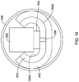
- FIG. 14 illustrates an example flexible circuit disposed within a tubular tine
- FIGS. 15-16 illustrate a portion of an example flexible circuit
- FIGS. 17-18 illustrate a portion of an example flexible circuit
- FIGS. 19-20 illustrate a portion of an example flexible circuit
- references in the specification to “an embodiment”, “some embodiments”, “other embodiments”, etc. indicate that the embodiment described may include one or more particular features, structures, and/or characteristics. However, such recitations do not necessarily mean that all embodiments include the particular features, structures, and/or characteristics. Additionally, when particular features, structures, and/or characteristics are described in connection with one embodiment, it should be understood that such features, structures, and/or characteristics may also be used connection with other embodiments whether or not explicitly described unless clearly stated to the contrary.
- Radiofrequency ablation systems may be utilized to create lesions within a target tissue such as a tumor.
- An example radiofrequency ablation system may include a single tine monopolar system that includes a needle electrode.
- the needle electrode may be activated to create relatively discrete lesions.
- the needle electrode may be repositioned, for example repeatedly repositioned, and activated at different locations. While effective, the lesions may be inconsistent and/or non-homogenous.
- Other example radiofrequency ablation systems may include a plurality of monopolar tines. Such systems may overcome some of the limitations of the single tine systems. However, these systems could overheat, which could also result in non-homogenous lesions.
- the medical devices, ablation devices, and/or ablation device systems disclosed herein are designed to overcome at least some of the limitations of single and/or multiple tine monopolar ablation systems.
- the ablation devices disclosed herein may utilize arrays of ablation tines that may be capable of bipolar energization.
- the devices disclosed herein may be capable of creating relatively homogenous lesions of a variety of different sizes (e.g., up to about 10-250 cm 3 or more).
- the devices disclosed herein may be designed to improve the quality of the ablation and/or reduce the ablation procedure time.
- FIG. 1 illustrates an embodiment of a medical device 10 according to the invention.
- Medical device 10 may include a shaft 12 .
- a proximal array of tines 14 may be coupled to shaft 12 , for example along a distal region of shaft 12 .
- Proximal array 14 may include a plurality of individual tines such as tines 16 a / 16 b / 16 c / 16 d / 16 e / 16 f .
- a distal array of tines 18 may be coupled to shaft 12 , for example along a distal region of shaft 12 .
- Distal array 18 may include a plurality of individual tines such as tines 20 a / 20 b / 20 c / 20 d / 20 e / 20 f .
- proximal array 14 includes six tines 16 a / 16 b / 16 c / 16 d / 16 e / 16 f and distal array 18 also includes six tines 20 a / 20 b / 20 c / 20 d / 20 e / 20 f .
- Proximal array 14 and distal array 18 may include a suitable number of tines such as two, three, four, five, six, seven, eight, or more tines.
- the number of tines in arrays 14 / 18 may or may not be the same.
- the tines in arrays 14 / 18 may have a diameter in the range of about 0.001-0.01 inches (e.g., about 0.00254-0.0254 cm) and may have lengths on the order of 0.1 cm to several centimeters.
- Proximal array 14 and/or distal array 18 may project radially outward from shaft 12 .
- tines 16 a / 16 b / 16 c / 16 d / 16 e / 16 f may be generally planar.
- tines 20 a / 20 b / 20 c / 20 d / 20 e / 20 f may also be generally planar.
- tines 16 a / 16 b / 16 c / 16 d / 16 e / 16 f and tines 20 a / 20 b / 20 c / 20 d / 20 e / 20 f may lie within generally parallel planes. In other embodiments, the planes may not be parallel with one another. These are just examples. Other arrangements are contemplated.
- tines 16 a / 16 b / 16 c / 16 d / 16 e / 16 f / 20 a / 20 b / 20 c / 20 d / 20 e / 20 f may take the form of solid wire or tubular member.
- tine 16 a may include an inert, electrically conductive member taking the form of a tube.
- Tine 16 a may include an electrode assembly or flexible circuit disposed therein.
- the structure of the flexible circuit may be the same or similar to the flexible circuits disclosed herein.
- the flexible circuits may include a substrate, one or more electrodes, and one or more temperature sensors.
- one or more electrodes may be coupled to tine 16 a (e.g., along an outer surface of tine 16 a ).
- the one or more electrodes disposed within tine 16 a may be in electrical contact with tine 16 a such that tine 16 a may be considered as an electrode or ablation member. Accordingly, energy supplied to the one or more electrodes of the flexible circuit may be conducted to tine 16 a and, ultimately, to a target tissue.
- the tines 16 a / 16 b / 16 c / 16 d / 16 e / 16 f / 20 a / 20 b / 20 c / 20 d / 20 e / 20 f may be electrically insulated from one another.
- device 10 may include arrays 14 / 18 of tines 16 a / 16 b / 16 c / 16 d / 16 e / 16 f / 20 a / 20 b / 20 c / 20 d / 20 e / 20 f , tines 16 a / 16 b / 16 c / 16 d / 16 e / 16 f / 20 a / 20 b / 20 c / 20 d / 20 e / 20 f may define one or more pairs of bipolar electrodes.
- the pairs of bipolar electrodes may be defined with a given array (e.g., tine 16 a and tine 16 b may define a pair of bipolar electrodes) or across arrays (e.g., tine 16 a and tine 20 a may define a pair of bipolar electrodes).
- a controller or processor 21 may be coupled to device 10 .
- Processor 21 may be electrically coupled to (e.g., via wires or other suitable structures) the electrodes and temperature sensors disposed along/within the various tines 16 a / 16 b / 16 c / 16 d / 16 e / 16 f / 20 a / 20 b / 20 c / 20 d / 20 e / 20 f .
- processor 21 may include one or more RF generators. Other processors and/or power sources are contemplated.
- Processor 21 may be capable of modulating the amount of power supplied to each of the electrodes based on temperature feedback provided by the temperature sensors. For example, processor 21 may be capable of reducing (or stopping) power supplied to a particular electrode or set of electrodes when temperature feedback from temperature sensors positioned adjacent to the electrodes indicates a greater extent of heating than desired (e.g., the temperature adjacent to a subset of electrodes is approaching, has reached, or has exceeded a pre-determined temperature threshold). Analogously, processor 21 may also be capable of throttling up the power to a subset of electrodes where the temperature adjacent to these electrodes is lower than desired.
- Processor 21 may also be capable of modulating the amount of power supplied to each of the electrodes based on impedance sensing in addition to or alternatively to temperature sensing. Modulation of power may allow for more even heating and/or lesion creation as well as more homogenous lesions. In addition, the phase angle between the voltage and the current may also be measured, which may allow for more accurate calculation of impedance and/or power.
- processor 21 may also be capable of determining and/or choosing the particular tines 16 a / 16 b / 16 c / 16 d / 16 e / 16 f / 20 a / 20 b / 20 c / 20 d / 20 e / 20 f that may be utilized to form a pair of bipolar electrodes that would best fulfill the needs of a given intervention. For example, if addition heat energy is needed adjacent to or between a particular pair of tines (e.g., between tine 16 a and tine 20 a ), processor 21 may be capable of activating the one or more electrodes within tines 16 a / 20 a in the appropriate manner so as to define the suitable pair of bipolar electrodes.
- processor 21 may be capable of switching the electrodes within tines 16 a / 20 a (and/or any of tines 16 a / 16 b / 16 c / 16 d / 16 e / 16 f / 20 a / 20 b / 20 c / 20 d / 20 e / 20 f ) between a power/sourcing state, a ground/synching state, or an open/passing state.
- the electrodes within tines 16 a / 16 b / 16 c / 16 d / 16 e / 16 f / 20 a / 20 b / 20 c / 20 d / 20 e / 20 f may be considered “tripolar”.
- processor 21 is capable of firing one pair of electrodes/tines or multiple pairs of electrodes/tines simultaneously.
- Fast switching relays may be used to change between these states. This may include the use of switching utilizing solid state circuitry.
- processor 21 may utilize an algorithm where temperature is used to determine where the greatest “need” (e.g., temperature is furthest below the target temperature).
- the electrode/tine where the greatest need is present may be defined as the “dominant” electrode.
- the dominant electrode may be set in the power/sourcing state. Electrodes that are above the target temperature threshold may be set to open/passing. In instances where only one electrode is below the target temperature, setting the electrodes above the temperature threshold to open/passing allows at least one pair of electrodes to fire (e.g., the dominant electrode below the temperature threshold paired with the electrode with the smallest temperature surplus). The remaining electrodes/tines may be set to ground/synching.
- the process may be repeated.
- the time interval for each cycle of the algorithm may be on the order of about 1-30 ms, or about 1-25 ms, or about 1 ms, or about 10 ms, or about 25 ms.
- Other algorithms are contemplated. For example, algorithms are contemplated where instead of selecting only one dominant electrode, two (or more) electrodes with the highest temperature deficits could be selected as “co-dominant” electrodes.
- Shaft 12 may define one or more lumens.
- shaft 12 may define lumen 22 , which may take the form of a guidewire lumen.
- shaft 12 may also define a plurality of tine lumens 24 .
- Tines 16 a / 16 b / 16 c / 16 d / 16 e / 16 f and/or tines 20 a / 20 b / 20 c / 20 d / 20 e / 20 f may be disposed within lumens 24 .
- each tine 16 a / 16 b / 16 c / 16 d / 16 e / 16 f / 20 a / 20 b / 20 c / 20 d / 20 e / 20 f may lie within its own lumen 24 .
- one or more of tines 16 a / 16 b / 16 c / 16 d / 16 e / 16 f / 20 a / 20 b / 20 c / 20 d / 20 e / 20 f may share one of lumens 24 .
- tines 16 a / 16 b / 16 c / 16 d / 16 e / 16 f / 20 a / 20 b / 20 c / 20 d / 20 e / 20 f may be movable within lumens 24 .
- tines 16 a / 16 b / 16 c / 16 d / 16 e / 16 f / 20 a / 20 b / 20 c / 20 d / 20 e / 20 f may shift between a first or “unexpanded” configuration where tines 16 a / 16 b / 16 c / 16 d / 16 e / 16 f / 20 a / 20 b / 20 c / 20 d / 20 e / 20 f lie along shaft 12 and/or within lumens 24 and a second or “expanded” configuration where tines 16 a / 16 b / 16 c / 16 d / 16 e / 16 f / 20 a / 20 b / 20 c / 20 d / 20 e / 20 f project radially from shaft 12 .
- tines 16 a / 16 b / 16 c / 16 d / 16 e / 16 f / 20 a / 20 b / 20 c / 20 d / 20 e / 20 f may be circumferentially aligned.
- tine 16 a may be circumferentially aligned with tine 20 a .
- tines 16 a / 16 b / 16 c / 16 d / 16 e / 16 f and tines 20 a / 20 b / 20 c / 20 d / 20 e / 20 f may be circumferentially offset from one another as shown in FIG. 3 .
- FIG. 4 illustrates another example medical device 110 that may be similar in form and function to other medical devices disclosed herein.
- Device 110 may include shaft 112 .
- a handle 126 may be coupled to the proximal end of shaft 112 .
- Proximal and distal arrays of tines 114 / 118 may be disposed along shaft 112 .
- arrays 114 / 118 may include curved tines. The curved tines may allow arrays 114 / 118 to cover a greater amount of surface area.
- a control wire 128 may be disposed within shaft 112 as shown in FIG. 5 .
- Control wire 128 may be coupled to proximal and distal arrays of tines 114 / 118 so that proximal and distal arrays of tines 114 / 118 can be shifted between a first “non-expanded” configuration and an expanded configuration.
- control wire 128 may provide power to flexible circuits disposed within proximal and distal arrays of tines 114 / 118 .
- separate power wires may be used.
- the separate power wires may be insulated from one another.
- one or more control members 128 a / 128 b may be disposed at handle 126 as shown in FIG. 6 . Control members 128 a / 128 b may be capable of shifting proximal and distal arrays of tines 114 / 118 between the non-expanded and expanded configurations.
- FIGS. 7-8 illustrate an example flexible circuit 130 that may be used with any of the devices disclosed herein.
- flexible circuit 130 (and/or other flexible circuits disclosed herein) may be used by disposing flexible circuit 130 within the tines of the medical devices disclosed herein. Doing so may allow the tines to function as electrodes and/or an ablation surface.
- Flexible circuit 130 may include a substrate 132 .
- Substrate 132 may include a suitable material such as one or more polymers.
- the polymer(s) may include a suitable material such as those disclosed herein.
- substrate 132 may include a polyimide.
- a conductive member or trace 134 may extend along a first side 132 a of substrate 132 .
- Conductive trace 134 may be a printed, plated, deposited, or the like on substrate 132 .
- conductive trace 134 may include a conductive material such as copper, gold, gold-plated copper, conductive ink, or the like.
- a temperature sensor 138 may be coupled to conductive trace 134 .
- Temperature sensor 138 may include a thermistor, a thermocouple, or another suitable temperature sensor.
- Conductive trace 134 may be electrically coupled to another conductive member or trace 140 on a second side 132 b of substrate 132 by a via 136 .
- One or more active traces, for example traces 142 / 144 may also be disposed along second side 132 b .
- Traces 142 / 144 may define one or more electrodes.
- Manufacturing flexible circuit 130 may include suitably disposing trace 134 on substrate 132 , coupling temperature sensor 138 to trace 134 , forming via 136 , and coupling traces 140 / 142 / 144 to substrate 132 .
- a plurality of flexible circuits 130 may be arranged in an array as shown in FIG. 9 .
- four flexible circuits 130 a / 130 b / 130 c / 130 d are arranged in an array.
- flexible circuits 130 a / 130 b / 130 c / 130 d may be disposed within a tine.
- FIG. 10 illustrates flexible circuit 130 folded and disposed within a tine 146 .
- flexible circuit 130 may include one or more fold lines or scores to aid in folding flexible circuit 130 within tine 146 .
- manufacturing medical device 110 may include folding flexible circuit 130 and disposing flexible circuit 130 within tine 146 .
- flexible circuits 130 may be separate members that are disposed within individual tines (e.g., tine 146 ) of an array of tines.
- an individual flexible circuit 130 is disposed in each of the individual tines 146 .
- a flexible circuit assembly 230 may be formed that includes a plurality of individual flexible circuit sections 230 a / 230 b / 230 c / 230 d as shown in FIG. 11 .
- Assembly 230 may be disposed in an array as shown in FIG. 12 and, ultimately, individual flexible circuit sections 230 a / 230 b / 230 c / 230 d may be disposed within a tine.
- FIGS. 13-14 illustrate another example flexible circuit 330 that may be similar to other flexible circuits disclosed herein.
- Flexible circuit 330 may include substrate 332 .
- the first side 332 a of substrate 332 may resemble first side 132 a of flexible circuit 130 as shown in FIG. 7 .
- first side 332 a may include conductive trace 334 and temperature sensor 338 .
- the second side 332 b of substrate 332 may include a layer of conductive material 342 .
- Layer 342 may be coupled to conductive trace 334 by via 336 .
- Flexible circuit 330 may be folded and disposed within tine 346 (e.g., as shown in FIG. 14 ).
- FIGS. 15-16 illustrate another example flexible circuit 430 that may be similar to other flexible circuits disclosed herein.
- Flexible circuit 430 may include substrate 432 .
- Conductive trace 434 and return trace 440 may be disposed along first side 432 a of substrate 432 .
- Temperature sensor 438 may be coupled to traces 434 / 440 .
- the second side of substrate 432 may include a layer of conductive material 442 .
- FIGS. 17-18 illustrate another example flexible circuit 530 that may be similar to other flexible circuits disclosed herein.
- Flexible circuit 530 may include substrate 532 .
- the first side 532 a of substrate 532 may include conductive trace 534 .
- a plurality of temperature sensors 538 a / 538 b / 538 c may be coupled to conductive trace 534 .
- the second side of substrate 532 may include a layer of conductive material 542 .
- Layer 542 may be coupled to conductive trace 534 by via 536 .
- FIGS. 19-20 illustrate another example flexible circuit 630 that may be similar to other flexible circuits disclosed herein.
- Flexible circuit 630 may include substrate 332 .
- Conductive trace 634 and return trace 640 may be disposed along first side 632 a of substrate 632 .
- a plurality of temperature sensor 638 a / 638 b / 638 c may be coupled to traces 634 / 640 .
- the second side of substrate 632 may include a layer of conductive material 642 .
- the materials that can be used for the various components of medical device 10 (and/or other medical devices disclosed herein) and the various tubular members disclosed herein may include those commonly associated with medical devices.
- the following discussion makes reference to shaft 12 and other components of medical device 10 .
- this is not intended to limit the devices and methods described herein, as the discussion may be applied to other tubular members and/or components of tubular members or devices disclosed herein.
- Shaft 12 may be made from a metal, metal alloy, polymer (some examples of which are disclosed below), a metal-polymer composite, ceramics, combinations thereof, and the like, or other suitable material.
- suitable metals and metal alloys include stainless steel, such as 304V, 304L, and 316LV stainless steel; mild steel; nickel-titanium alloy such as linear-elastic and/or super-elastic nitinol; other nickel alloys such as nickel-chromium-molybdenum alloys (e.g., UNS: N06625 such as INCONEL® 625, UNS: N06022 such as HASTELLOY® UNS: N10276 such as HASTELLOY® C276®, other HASTELLOY® alloys, and the like), nickel-copper alloys (e.g., UNS: N04400 such as MONEL® 400, NICKELVAC® 400, NICORROS® 400, and the like), nickel-cobalt-chrom
- linear elastic and/or non-super-elastic nitinol may be distinguished from super elastic nitinol in that the linear elastic and/or non-super-elastic nitinol does not display a substantial “superelastic plateau” or “flag region” in its stress/strain curve like super elastic nitinol does.
- linear elastic and/or non-super-elastic nitinol as recoverable strain increases, the stress continues to increase in a substantially linear, or a somewhat, but not necessarily entirely linear relationship until plastic deformation begins or at least in a relationship that is more linear that the super elastic plateau and/or flag region that may be seen with super elastic nitinol.
- linear elastic and/or non-super-elastic nitinol may also be termed “substantially” linear elastic and/or non-super-elastic nitinol.
- linear elastic and/or non-super-elastic nitinol may also be distinguishable from super elastic nitinol in that linear elastic and/or non-super-elastic nitinol may accept up to about 2-5% strain while remaining substantially elastic (e.g., before plastically deforming) whereas super elastic nitinol may accept up to about 8% strain before plastically deforming. Both of these materials can be distinguished from other linear elastic materials such as stainless steel (that can also can be distinguished based on its composition), which may accept only about 0.2 to 0.44 percent strain before plastically deforming.
- the linear elastic and/or non-super-elastic nickel-titanium alloy is an alloy that does not show any martensite/austenite phase changes that are detectable by differential scanning calorimetry (DSC) and dynamic metal thermal analysis (DMTA) analysis over a large temperature range.
- DSC differential scanning calorimetry
- DMTA dynamic metal thermal analysis
- the mechanical bending properties of such material may therefore be generally inert to the effect of temperature over this very broad range of temperature.
- the mechanical bending properties of the linear elastic and/or non-super-elastic nickel-titanium alloy at ambient or room temperature are substantially the same as the mechanical properties at body temperature, for example, in that they do not display a super-elastic plateau and/or flag region.
- the linear elastic and/or non-super-elastic nickel-titanium alloy maintains its linear elastic and/or non-super-elastic characteristics and/or properties.
- the linear elastic and/or non-super-elastic nickel-titanium alloy may be in the range of about 50 to about 60 weight percent nickel, with the remainder being essentially titanium. In some embodiments, the composition is in the range of about 54 to about 57 weight percent nickel.
- a suitable nickel-titanium alloy is FHP-NT alloy commercially available from Furukawa Techno Material Co. of Kanagawa, Japan. Some examples of nickel titanium alloys are disclosed in U.S. Pat. Nos. 5,238,004 and 6,508,803, which are incorporated herein by reference. Other suitable materials may include ULTANIUMTM (available from Neo-Metrics) and GUM METALTM (available from Toyota).
- a superelastic alloy for example a superelastic nitinol can be used to achieve desired properties.
- portions or all of shaft 12 may also be doped with, made of, or otherwise include a radiopaque material.
- Radiopaque materials are understood to be materials capable of producing a relatively bright image on a fluoroscopy screen or another imaging technique during a medical procedure. This relatively bright image aids the user of medical device 10 in determining its location.
- Some examples of radiopaque materials can include, but are not limited to, gold, platinum, palladium, tantalum, tungsten alloy, polymer material loaded with a radiopaque filler, and the like. Additionally, other radiopaque marker bands and/or coils may also be incorporated into the design of medical device 10 to achieve the same result.
- a degree of Magnetic Resonance Imaging (MRI) compatibility is imparted into medical device 10 .
- shaft 12 or portions thereof may be made of a material that does not substantially distort the image and create substantial artifacts (i.e., gaps in the image). Certain ferromagnetic materials, for example, may not be suitable because they may create artifacts in an MRI image. Shaft 12 , or portions thereof, may also be made from a material that the MRI machine can image.
- Some materials that exhibit these characteristics include, for example, tungsten, cobalt-chromium-molybdenum alloys (e.g., UNS: R30003 such as ELGILOY®, PHYNOX®, and the like), nickel-cobalt-chromium-molybdenum alloys (e.g., UNS: R30035 such as MP35-N® and the like), nitinol, and the like, and others.
- cobalt-chromium-molybdenum alloys e.g., UNS: R30003 such as ELGILOY®, PHYNOX®, and the like
- nickel-cobalt-chromium-molybdenum alloys e.g., UNS: R30035 such as MP35-N® and the like
- nitinol and the like, and others.
- a sheath or covering may be disposed over portions or all of shaft 12 that may define a generally smooth outer surface for medical device 10 . In other embodiments, however, such a sheath or covering may be absent from a portion of all of medical device 10 , such that shaft 12 may form the outer surface.
- the sheath may be made from a polymer or other suitable material.
- suitable polymers may include polytetrafluoroethylene (PTFE), ethylene tetrafluoroethylene (ETFE), fluorinated ethylene propylene (FEP), polyoxymethylene (POM, for example, DELRIN® available from DuPont), polyether block ester, polyurethane (for example, Polyurethane 85A), polypropylene (PP), polyvinylchloride (PVC), polyether-ester (for example, ARNITEL® available from DSM Engineering Plastics), ether or ester based copolymers (for example, butylene/poly(alkylene ether) phthalate and/or other polyester elastomers such as HYTREL® available from DuPont), polyamide (for example, DURETHAN® available from Bayer or CRISTAMID® available from Elf Atochem), elastomeric polyamides, block polyamide/ethers, polyether block amide (PEBA, for example available under the trade name PEBAX®), ethylene vinyl acetate
- the exterior surface of the medical device 10 may be sandblasted, beadblasted, sodium bicarbonate-blasted, electropolished, etc.
- a coating for example a lubricious, a hydrophilic, a protective, or other type of coating may be applied over portions or all of the sheath, or in embodiments without a sheath over portion of shaft 12 , or other portions of medical device 10 .
- the sheath may comprise a lubricious, hydrophilic, protective, or other type of coating.
- Hydrophobic coatings such as fluoropolymers provide a dry lubricity which improves guidewire handling and device exchanges.
- Lubricious coatings improve steerability and improve lesion crossing capability.
- Suitable lubricious polymers are well known in the art and may include silicone and the like, hydrophilic polymers such as high-density polyethylene (HDPE), polytetrafluoroethylene (PTFE), polyarylene oxides, polyvinylpyrolidones, polyvinylalcohols, hydroxy alkyl cellulosics, algins, saccharides, caprolactones, and the like, and mixtures and combinations thereof.
- HDPE high-density polyethylene
- PTFE polytetrafluoroethylene
- polyarylene oxides polyvinylpyrolidones
- polyvinylalcohols polyvinylalcohols
- hydroxy alkyl cellulosics algins
- Hydrophilic polymers may be blended among themselves or with formulated amounts of water insoluble compounds (including some polymers) to yield coatings with suitable lubricity, bonding, and solubility.
- the coating and/or sheath may be formed, for example, by coating, extrusion, co-extrusion, interrupted layer co-extrusion (ILC), or fusing several segments end-to-end.
- the layer may have a uniform stiffness or a gradual reduction in stiffness from the proximal end to the distal end thereof. The gradual reduction in stiffness may be continuous as by ILC or may be stepped as by fusing together separate extruded tubular segments.
- the outer layer may be impregnated with a radiopaque filler material to facilitate radiographic visualization. Those skilled in the art will recognize that these materials can vary widely without deviating from the scope of the present invention.
Landscapes
- Health & Medical Sciences (AREA)
- Surgery (AREA)
- Engineering & Computer Science (AREA)
- Life Sciences & Earth Sciences (AREA)
- Biomedical Technology (AREA)
- Molecular Biology (AREA)
- Nuclear Medicine, Radiotherapy & Molecular Imaging (AREA)
- Plasma & Fusion (AREA)
- Physics & Mathematics (AREA)
- Heart & Thoracic Surgery (AREA)
- Medical Informatics (AREA)
- Otolaryngology (AREA)
- Animal Behavior & Ethology (AREA)
- General Health & Medical Sciences (AREA)
- Public Health (AREA)
- Veterinary Medicine (AREA)
- Cardiology (AREA)
- Surgical Instruments (AREA)
Priority Applications (2)
| Application Number | Priority Date | Filing Date | Title |
|---|---|---|---|
| US14/796,711 US11090107B2 (en) | 2014-07-11 | 2015-07-10 | Ablation medical devices |
| US17/396,375 US20210361344A1 (en) | 2014-07-11 | 2021-08-06 | Ablation medical devices |
Applications Claiming Priority (2)
| Application Number | Priority Date | Filing Date | Title |
|---|---|---|---|
| US201462023621P | 2014-07-11 | 2014-07-11 | |
| US14/796,711 US11090107B2 (en) | 2014-07-11 | 2015-07-10 | Ablation medical devices |
Related Child Applications (1)
| Application Number | Title | Priority Date | Filing Date |
|---|---|---|---|
| US17/396,375 Continuation US20210361344A1 (en) | 2014-07-11 | 2021-08-06 | Ablation medical devices |
Publications (2)
| Publication Number | Publication Date |
|---|---|
| US20160008053A1 US20160008053A1 (en) | 2016-01-14 |
| US11090107B2 true US11090107B2 (en) | 2021-08-17 |
Family
ID=53761531
Family Applications (2)
| Application Number | Title | Priority Date | Filing Date |
|---|---|---|---|
| US14/796,711 Active 2037-07-10 US11090107B2 (en) | 2014-07-11 | 2015-07-10 | Ablation medical devices |
| US17/396,375 Pending US20210361344A1 (en) | 2014-07-11 | 2021-08-06 | Ablation medical devices |
Family Applications After (1)
| Application Number | Title | Priority Date | Filing Date |
|---|---|---|---|
| US17/396,375 Pending US20210361344A1 (en) | 2014-07-11 | 2021-08-06 | Ablation medical devices |
Country Status (6)
| Country | Link |
|---|---|
| US (2) | US11090107B2 (ja) |
| EP (1) | EP3166525B1 (ja) |
| JP (1) | JP6229077B2 (ja) |
| CN (1) | CN106456241B (ja) |
| AU (1) | AU2015287652B2 (ja) |
| WO (1) | WO2016007901A1 (ja) |
Families Citing this family (2)
| Publication number | Priority date | Publication date | Assignee | Title |
|---|---|---|---|---|
| US11944372B2 (en) | 2018-10-23 | 2024-04-02 | Boston Scientific Scimed, Inc. | Ablation probe system with center working channel |
| US11419671B2 (en) * | 2018-12-11 | 2022-08-23 | Neurent Medical Limited | Systems and methods for therapeutic nasal neuromodulation |
Citations (28)
| Publication number | Priority date | Publication date | Assignee | Title |
|---|---|---|---|---|
| US5156151A (en) * | 1991-02-15 | 1992-10-20 | Cardiac Pathways Corporation | Endocardial mapping and ablation system and catheter probe |
| US5228442A (en) * | 1991-02-15 | 1993-07-20 | Cardiac Pathways Corporation | Method for mapping, ablation, and stimulation using an endocardial catheter |
| US5238004A (en) | 1990-04-10 | 1993-08-24 | Boston Scientific Corporation | High elongation linear elastic guidewire |
| US5415166A (en) | 1991-02-15 | 1995-05-16 | Cardiac Pathways Corporation | Endocardial mapping apparatus and cylindrical semiconductor device mounting structure for use therewith and method |
| US5456254A (en) * | 1991-02-15 | 1995-10-10 | Cardiac Pathways Corp | Flexible strip assembly having insulating layer with conductive pads exposed through insulating layer and device utilizing the same |
| US5465717A (en) * | 1991-02-15 | 1995-11-14 | Cardiac Pathways Corporation | Apparatus and Method for ventricular mapping and ablation |
| US5499981A (en) * | 1993-03-16 | 1996-03-19 | Ep Technologies, Inc. | Flexible interlaced multiple electrode assemblies |
| US5772609A (en) | 1993-05-11 | 1998-06-30 | Target Therapeutics, Inc. | Guidewire with variable flexibility due to polymeric coatings |
| EP0644738B1 (en) | 1993-04-07 | 2000-03-08 | Cardiac Pathways Corporation | Apparatus for ventricular mapping and ablation |
| US6139510A (en) | 1994-05-11 | 2000-10-31 | Target Therapeutics Inc. | Super elastic alloy guidewire |
| US6508803B1 (en) | 1998-11-06 | 2003-01-21 | Furukawa Techno Material Co., Ltd. | Niti-type medical guide wire and method of producing the same |
| US20040158239A1 (en) * | 2000-09-15 | 2004-08-12 | Behl Robert S. | Methods and systems for focused bipolar tissue ablation |
| US20050054905A1 (en) * | 2003-09-09 | 2005-03-10 | Corl Paul D. | Apparatus for ascertaining blood characteristics and probe for use therewith |
| US20060058676A1 (en) * | 2002-04-17 | 2006-03-16 | Tomoyuki Yagi | Ultrasonic probe in body cavity |
| US20060244177A1 (en) * | 2005-04-19 | 2006-11-02 | Masayuki Kaneto | Flexible printed circuit board for catheter, catheter using same, and production method of catheter |
| US20070219551A1 (en) * | 2003-09-22 | 2007-09-20 | Honour Kirk S | Medical device with flexible printed circuit |
| US20080255553A1 (en) | 2007-04-13 | 2008-10-16 | Boston Scientific Scimed, Inc. | Radiofrequency ablation device |
| US20090143651A1 (en) * | 2006-06-01 | 2009-06-04 | Bengt Kallback | Device for Invasive Use |
| US20090240249A1 (en) | 2004-11-08 | 2009-09-24 | Cardima, Inc. | System and Method for Performing Ablation and Other Medical Procedures Using An Electrode Array with Flexible Circuit |
| US20100094279A1 (en) * | 2006-10-10 | 2010-04-15 | Kauphusman James V | Circuit for a catheter or sheath and method of forming same |
| US20110024186A1 (en) * | 2009-06-10 | 2011-02-03 | Medtronic, Inc. | Lead apparatus |
| US20120150009A1 (en) * | 2010-12-14 | 2012-06-14 | Sorin Crm Sas | Lead For An Active Implantable Medical Device Wtih A Chip For Electrode Multiplexing |
| US20120172696A1 (en) * | 2009-09-10 | 2012-07-05 | Cathprint Ab | Flexible Conductor Carrier for Catheter and Catheter Fitted with a Conductor Carrier |
| US20120271138A1 (en) * | 2011-04-22 | 2012-10-25 | Topera, Inc. | Basket style cardiac mapping catheter having a flexible electrode assembly for detection of cardiac rhythm disorders |
| US20130282084A1 (en) * | 2004-09-10 | 2013-10-24 | Vessix Vascular, Inc. | Apparatus and Method for Treatment of In-Stent Restenosis |
| US20140018788A1 (en) * | 2012-07-04 | 2014-01-16 | Zoar Jacob ENGELMAN | Devices and Systems for Carotid Body Ablation |
| WO2014070999A2 (en) * | 2012-11-05 | 2014-05-08 | Landy Toth | Systems, methods, and devices for monitoring and treatment of tissues within and/or through a lumen wall |
| US20150105645A1 (en) * | 2013-10-14 | 2015-04-16 | Boston Scientific Scimed, Inc. | High resolution cardiac mapping electrode array catheter |
Family Cites Families (4)
| Publication number | Priority date | Publication date | Assignee | Title |
|---|---|---|---|---|
| DE69425249T2 (de) * | 1993-03-16 | 2001-03-22 | Ep Technologies | Träger-anordnung für mehrfach-elektroden |
| US5722401A (en) * | 1994-10-19 | 1998-03-03 | Cardiac Pathways Corporation | Endocardial mapping and/or ablation catheter probe |
| US20020022864A1 (en) * | 2000-06-07 | 2002-02-21 | Mahvi David M. | Multipolar electrode system for radiofrequency ablation |
| US8251991B2 (en) * | 2007-11-14 | 2012-08-28 | Halt Medical Inc. | Anchored RF ablation device for the destruction of tissue masses |
-
2015
- 2015-07-10 AU AU2015287652A patent/AU2015287652B2/en not_active Ceased
- 2015-07-10 JP JP2016565161A patent/JP6229077B2/ja active Active
- 2015-07-10 EP EP15742461.5A patent/EP3166525B1/en active Active
- 2015-07-10 US US14/796,711 patent/US11090107B2/en active Active
- 2015-07-10 CN CN201580032698.8A patent/CN106456241B/zh active Active
- 2015-07-10 WO PCT/US2015/040017 patent/WO2016007901A1/en active Application Filing
-
2021
- 2021-08-06 US US17/396,375 patent/US20210361344A1/en active Pending
Patent Citations (28)
| Publication number | Priority date | Publication date | Assignee | Title |
|---|---|---|---|---|
| US5238004A (en) | 1990-04-10 | 1993-08-24 | Boston Scientific Corporation | High elongation linear elastic guidewire |
| US5156151A (en) * | 1991-02-15 | 1992-10-20 | Cardiac Pathways Corporation | Endocardial mapping and ablation system and catheter probe |
| US5228442A (en) * | 1991-02-15 | 1993-07-20 | Cardiac Pathways Corporation | Method for mapping, ablation, and stimulation using an endocardial catheter |
| US5415166A (en) | 1991-02-15 | 1995-05-16 | Cardiac Pathways Corporation | Endocardial mapping apparatus and cylindrical semiconductor device mounting structure for use therewith and method |
| US5456254A (en) * | 1991-02-15 | 1995-10-10 | Cardiac Pathways Corp | Flexible strip assembly having insulating layer with conductive pads exposed through insulating layer and device utilizing the same |
| US5465717A (en) * | 1991-02-15 | 1995-11-14 | Cardiac Pathways Corporation | Apparatus and Method for ventricular mapping and ablation |
| US5499981A (en) * | 1993-03-16 | 1996-03-19 | Ep Technologies, Inc. | Flexible interlaced multiple electrode assemblies |
| EP0644738B1 (en) | 1993-04-07 | 2000-03-08 | Cardiac Pathways Corporation | Apparatus for ventricular mapping and ablation |
| US5772609A (en) | 1993-05-11 | 1998-06-30 | Target Therapeutics, Inc. | Guidewire with variable flexibility due to polymeric coatings |
| US6139510A (en) | 1994-05-11 | 2000-10-31 | Target Therapeutics Inc. | Super elastic alloy guidewire |
| US6508803B1 (en) | 1998-11-06 | 2003-01-21 | Furukawa Techno Material Co., Ltd. | Niti-type medical guide wire and method of producing the same |
| US20040158239A1 (en) * | 2000-09-15 | 2004-08-12 | Behl Robert S. | Methods and systems for focused bipolar tissue ablation |
| US20060058676A1 (en) * | 2002-04-17 | 2006-03-16 | Tomoyuki Yagi | Ultrasonic probe in body cavity |
| US20050054905A1 (en) * | 2003-09-09 | 2005-03-10 | Corl Paul D. | Apparatus for ascertaining blood characteristics and probe for use therewith |
| US20070219551A1 (en) * | 2003-09-22 | 2007-09-20 | Honour Kirk S | Medical device with flexible printed circuit |
| US20130282084A1 (en) * | 2004-09-10 | 2013-10-24 | Vessix Vascular, Inc. | Apparatus and Method for Treatment of In-Stent Restenosis |
| US20090240249A1 (en) | 2004-11-08 | 2009-09-24 | Cardima, Inc. | System and Method for Performing Ablation and Other Medical Procedures Using An Electrode Array with Flexible Circuit |
| US20060244177A1 (en) * | 2005-04-19 | 2006-11-02 | Masayuki Kaneto | Flexible printed circuit board for catheter, catheter using same, and production method of catheter |
| US20090143651A1 (en) * | 2006-06-01 | 2009-06-04 | Bengt Kallback | Device for Invasive Use |
| US20100094279A1 (en) * | 2006-10-10 | 2010-04-15 | Kauphusman James V | Circuit for a catheter or sheath and method of forming same |
| US20080255553A1 (en) | 2007-04-13 | 2008-10-16 | Boston Scientific Scimed, Inc. | Radiofrequency ablation device |
| US20110024186A1 (en) * | 2009-06-10 | 2011-02-03 | Medtronic, Inc. | Lead apparatus |
| US20120172696A1 (en) * | 2009-09-10 | 2012-07-05 | Cathprint Ab | Flexible Conductor Carrier for Catheter and Catheter Fitted with a Conductor Carrier |
| US20120150009A1 (en) * | 2010-12-14 | 2012-06-14 | Sorin Crm Sas | Lead For An Active Implantable Medical Device Wtih A Chip For Electrode Multiplexing |
| US20120271138A1 (en) * | 2011-04-22 | 2012-10-25 | Topera, Inc. | Basket style cardiac mapping catheter having a flexible electrode assembly for detection of cardiac rhythm disorders |
| US20140018788A1 (en) * | 2012-07-04 | 2014-01-16 | Zoar Jacob ENGELMAN | Devices and Systems for Carotid Body Ablation |
| WO2014070999A2 (en) * | 2012-11-05 | 2014-05-08 | Landy Toth | Systems, methods, and devices for monitoring and treatment of tissues within and/or through a lumen wall |
| US20150105645A1 (en) * | 2013-10-14 | 2015-04-16 | Boston Scientific Scimed, Inc. | High resolution cardiac mapping electrode array catheter |
Non-Patent Citations (6)
| Title |
|---|
| "Communication Pursuant to Article 94(3) EPC," for European Patent Application No. 15742461.5 dated May 7, 2020 (5 pages). |
| "Examination Report," for Australian Patent Application No. 2015287652 dated Jan. 24, 2017 (3 pages). |
| "International Preliminary Report on Patentability," for PCT Application No. PCT/US2015/040017 dated Jan. 26, 2017 (9 pages). |
| "International Search Report and Written Opinion," for PCT Application No. PCT/US2015/040017 dated Oct. 14, 2015 (12 pages). |
| "Response to Communication Pursuant to Article 94(3) EPC," for European Patent Application No. 15742461.5 filed Sep. 16, 2020 (14 pages). |
| "Second Office Action," for Chinese Patent Application No. 201580032698.8 dated Apr. 28, 2019 (9 pages) with English Summary. |
Also Published As
| Publication number | Publication date |
|---|---|
| JP2017513653A (ja) | 2017-06-01 |
| EP3166525A1 (en) | 2017-05-17 |
| JP6229077B2 (ja) | 2017-11-08 |
| EP3166525B1 (en) | 2021-08-25 |
| AU2015287652A1 (en) | 2016-10-20 |
| CN106456241A (zh) | 2017-02-22 |
| CN106456241B (zh) | 2020-04-28 |
| US20160008053A1 (en) | 2016-01-14 |
| AU2015287652B2 (en) | 2017-10-12 |
| WO2016007901A1 (en) | 2016-01-14 |
| US20210361344A1 (en) | 2021-11-25 |
Similar Documents
| Publication | Publication Date | Title |
|---|---|---|
| US20200222115A1 (en) | Medical devices with a flexible electrode assembly coupled to an ablation tip | |
| EP3024406B1 (en) | Medical devices for renal nerve ablation | |
| US9186210B2 (en) | Medical devices including ablation electrodes | |
| JP6313470B2 (ja) | 印刷された構成要素を備えた交感神経アブレーションのための医療機器およびその製造方法 | |
| US9456867B2 (en) | Open irrigated ablation catheter | |
| US9833283B2 (en) | Medical devices for renal nerve ablation | |
| US20130172880A1 (en) | Renal nerve modulation devices and methods for renal nerve modulation | |
| US20130172879A1 (en) | Renal nerve modulation medical devices | |
| US20210361344A1 (en) | Ablation medical devices | |
| EP3148427A1 (en) | Double micro-electrode catheter | |
| EP3148467A1 (en) | Nerve modulation devices with cooling capabilities | |
| EP3010435A1 (en) | Medical devices for renal nerve ablation | |
| US20210015553A1 (en) | Medical device having extenable members |
Legal Events
| Date | Code | Title | Description |
|---|---|---|---|
| AS | Assignment |
Owner name: BOSTON SCIENTIFIC SCIMED, INC., MINNESOTA Free format text: ASSIGNMENT OF ASSIGNORS INTEREST;ASSIGNORS:MATHUR, PRABODH;LEE, HENRY H.;DANDLER, ANDRES;AND OTHERS;SIGNING DATES FROM 20150613 TO 20150714;REEL/FRAME:036187/0847 |
|
| STPP | Information on status: patent application and granting procedure in general |
Free format text: DOCKETED NEW CASE - READY FOR EXAMINATION |
|
| STPP | Information on status: patent application and granting procedure in general |
Free format text: NON FINAL ACTION MAILED |
|
| STPP | Information on status: patent application and granting procedure in general |
Free format text: FINAL REJECTION MAILED |
|
| STPP | Information on status: patent application and granting procedure in general |
Free format text: DOCKETED NEW CASE - READY FOR EXAMINATION |
|
| STPP | Information on status: patent application and granting procedure in general |
Free format text: RESPONSE TO NON-FINAL OFFICE ACTION ENTERED AND FORWARDED TO EXAMINER |
|
| STPP | Information on status: patent application and granting procedure in general |
Free format text: RESPONSE AFTER FINAL ACTION FORWARDED TO EXAMINER |
|
| STCV | Information on status: appeal procedure |
Free format text: NOTICE OF APPEAL FILED |
|
| STCV | Information on status: appeal procedure |
Free format text: APPEAL BRIEF (OR SUPPLEMENTAL BRIEF) ENTERED AND FORWARDED TO EXAMINER |
|
| STPP | Information on status: patent application and granting procedure in general |
Free format text: NOTICE OF ALLOWANCE MAILED -- APPLICATION RECEIVED IN OFFICE OF PUBLICATIONS |
|
| STPP | Information on status: patent application and granting procedure in general |
Free format text: PUBLICATIONS -- ISSUE FEE PAYMENT RECEIVED |
|
| STPP | Information on status: patent application and granting procedure in general |
Free format text: PUBLICATIONS -- ISSUE FEE PAYMENT VERIFIED |
|
| STCF | Information on status: patent grant |
Free format text: PATENTED CASE |