US11083621B2 - Instrument for treating an ocular disorder - Google Patents
Instrument for treating an ocular disorder Download PDFInfo
- Publication number
- US11083621B2 US11083621B2 US16/590,228 US201916590228A US11083621B2 US 11083621 B2 US11083621 B2 US 11083621B2 US 201916590228 A US201916590228 A US 201916590228A US 11083621 B2 US11083621 B2 US 11083621B2
- Authority
- US
- United States
- Prior art keywords
- contact member
- eyelid margin
- debris
- eye
- eyelid
- Prior art date
- Legal status (The legal status is an assumption and is not a legal conclusion. Google has not performed a legal analysis and makes no representation as to the accuracy of the status listed.)
- Active
Links
Images


Classifications
-
- A—HUMAN NECESSITIES
- A61—MEDICAL OR VETERINARY SCIENCE; HYGIENE
- A61F—FILTERS IMPLANTABLE INTO BLOOD VESSELS; PROSTHESES; DEVICES PROVIDING PATENCY TO, OR PREVENTING COLLAPSING OF, TUBULAR STRUCTURES OF THE BODY, e.g. STENTS; ORTHOPAEDIC, NURSING OR CONTRACEPTIVE DEVICES; FOMENTATION; TREATMENT OR PROTECTION OF EYES OR EARS; BANDAGES, DRESSINGS OR ABSORBENT PADS; FIRST-AID KITS
- A61F9/00—Methods or devices for treatment of the eyes; Devices for putting-in contact lenses; Devices to correct squinting; Apparatus to guide the blind; Protective devices for the eyes, carried on the body or in the hand
- A61F9/007—Methods or devices for eye surgery
- A61F9/00709—Instruments for removing foreign bodies
-
- A—HUMAN NECESSITIES
- A61—MEDICAL OR VETERINARY SCIENCE; HYGIENE
- A61F—FILTERS IMPLANTABLE INTO BLOOD VESSELS; PROSTHESES; DEVICES PROVIDING PATENCY TO, OR PREVENTING COLLAPSING OF, TUBULAR STRUCTURES OF THE BODY, e.g. STENTS; ORTHOPAEDIC, NURSING OR CONTRACEPTIVE DEVICES; FOMENTATION; TREATMENT OR PROTECTION OF EYES OR EARS; BANDAGES, DRESSINGS OR ABSORBENT PADS; FIRST-AID KITS
- A61F13/00—Bandages or dressings; Absorbent pads
- A61F13/15—Absorbent pads, e.g. sanitary towels, swabs or tampons for external or internal application to the body; Supporting or fastening means therefor; Tampon applicators
- A61F13/38—Swabs having a stick-type handle, e.g. cotton tips
Definitions
- the present invention relates generally to a method and apparatus for treating an ocular disorder, and more particularly, to treating eyelid margin disease.
- Ocular disorders such as those relating to eyelid margin disease are particularly common pathological conditions of the ocular adenexa.
- these disorders include blepharitis, meibomitis, and dry eye syndrome.
- the recommended treatments for these exemplary common ocular disorders has remained essentially unchanged for decades.
- eyelid margin disease begins and ends with the patient.
- the patient first begins to notice symptoms including eyelid redness, flaking of skin on the eyelids, crusting and/or cysts at the eyelid margins, and a gritty sensation of the eye culminating in irritation, burning, and reduced vision. Should these symptoms remain unchanged or worsen, the patient routinely seeks the advice of an eye specialist, such as an ophthalmologist. After carefully considering the patients' medical history and investigating various possible causes, the specialist may prescribe a hygienic home treatment procedure for the patient to perform regularly in conjunction with antibiotics and/or topical steroids until the disease subsides.
- an eye specialist such as an ophthalmologist
- the goal of the hygienic home treatment procedure is to remove debris, oil, and scurf that have collected along the eyelid margin during progression of the disorder. Removal of this debris is critical to both healing the eye and preventing a resurgence of the disorder. Without proper, regular removal of accumulated debris, such ocular disorders regularly worsen despite periodic treatments.
- Hygienic home treatment of such ocular disorders is generally a two-step process.
- the patient softens the debris and scurf by applying a warm compress, diluted baby shampoo, or a specialized liquid solution to the eyelid margin.
- This first step is intended to prepare the debris for removal while preventing further irritation to the eye.
- the patient attempts to remove the debris by physically scrubbing the eyelid margin, the base of the eyelashes, and the pores of the meibomian glands. This scrubbing is routinely attempted with either a generic cotton swab, a fingertip, or a scrub pad placed over the fingertip and applied against the eye.
- the patient may improve the overall health of the eyelid margin; thereby reducing irritation, burning, and other symptoms related to the disorder.
- an instrument for the removal of debris from an eye during the treatment of an ocular disorder has a swab and a rigid member.
- the swab includes a tip portion sized to provide access to the debris on an eyelid of the eye.
- the rigid member has a distal end portion and a proximal end portion.
- the distal end portion of the rigid member is affixed to the swab, and the proximal end portion has a cross-sectional member profile.
- the cross-sectional member profile of the proximal end portion is non-circular and has a first groove.
- the first groove extends longitudinally along the proximal end portion for cooperating with a chuck such that rotation of the proximal end portion within the chuck is inhibited.
- One exemplary embodiment of a device for the removal of a debris from an eye during the treatment of an ocular disorder has a mechanical drive unit, a chuck, and an instrument.
- the chuck is connected to and is rotatably driven by the mechanical drive unit.
- the chuck also has an aperture extending at least partially therethrough with a cross-sectional aperture profile.
- the instrument is removably secured within the aperture and has a swab and a rigid member.
- the swab includes a tip portion sized to provide access to the debris on an eyelid of the eye.
- the rigid member has a distal end portion and a proximal end portion.
- the distal end portion of the rigid member is affixed to the swab, and the proximal end portion has a cross-sectional member profile configured to cooperate with the cross-sectional aperture profile of the aperture such that rotation of the proximal end portion within the aperture is inhibited.
- the mechanical drive unit rotatably drives the instrument via the chuck for removing debris.
- FIG. 1 is a perspective drawing of one embodiment of the device.
- FIG. 2 is a partially exploded perspective view of another embodiment of the device.
- FIG. 3A is an enlarged front view of the device of FIG. 2 .
- FIG. 3B is an enlarged front view of the device similar to FIG. 3A , but showing an instrument removably secured to a chuck.
- FIG. 4 is a top view of the chuck having a cross-sectional profile of the instrument in phantom lines.
- FIG. 5A is a drawing of the device of FIG. 1 treating a lower eyelid margin of an eye.
- FIG. 5B is a drawing of the device of FIG. 1 treating a upper eyelid margin of an eye.
- an embodiment of the device 10 for treating an ocular disorder includes a mechanical drive unit 12 which operably moves a swab 14 to facilitate removal of debris from an eye 15 (see FIGS. 5A-5B ).
- the swab 14 is connected to a rigid member 16 having both a distal end portion 18 and a proximal end portion 20 .
- the swab 14 is affixed to the distal end portion 18 of the rigid member 16 to create an instrument 22 , which may be secured to the mechanical drive unit 12 . As shown in FIG.
- the proximal end portion 20 is removably secured to the mechanical drive unit 12 in order to transmit motion from the mechanical drive unit 12 , through the rigid member 16 , and to the swab 14 .
- any known method may be used to removably secure the instrument 22 to the mechanical drive unit 12 .
- device 10 is not intended to be limited to the instrument 22 being removably secured to the mechanical drive unit 12 .
- the rigid member 16 may be either permanently secured or removably secured to either one of the swab 14 and/or the mechanical drive unit 12 .
- the swab 14 includes a tip portion 24 and a base portion 26 . While the swab 14 may be of a size sufficient to access debris on the eye 15 as shown in FIGS. 1, 5A, and 5B , at least the tip portion 24 is of a size sufficient to access debris on the eye 15 .
- the swab 14 has an approximate length between 1.0-3.0 millimeters and an approximate width of between 0.5-1.5 millimeters. More particularly, the swab 14 has an approximate length of 2 millimeters and an approximate width of 1 millimeter. It will be appreciated that the swab 14 may be manufactured of any material suitable for contacting the eye 15 without harming the eye 15 .
- the swab 14 is a sponge.
- “sponge” broadly refers to any material that is soft, porous, and resilient.
- the swab 14 is a medical grade sponge or a surgical grade sponge capable of removing debris from on the eye 15 without harming the eye 15 .
- the swab 14 is a methyl cellulose sponge. It will be appreciated; however, that similar materials capable of removing debris from on the eye 15 without harming the eye 15 are readily apparent and may also be used.
- the rigid member 16 is a plastic, cylindrical shaft including a central axis 27 .
- the shaft extends along the central axis 27 between the mechanical drive unit 12 and the swab 14 .
- the rigid member 16 is sufficiently rigid to effectively transmit motion from the mechanical drive unit 12 to the swab 14 .
- the swab 14 is permanently affixed to the distal end portion 18 by forming the base portion 26 to the rigid member 16 during manufacturing.
- any known method of affixing the swab 14 to the rigid member 16 may be used.
- any material or shaft shape may be used so long as the rigid member 16 is rigid enough to transmit sufficient motion from the mechanical drive unit 12 to the swab 14 in order to remove debris from on the eye 15 .
- the mechanical drive unit 12 includes a body 28 , an electric motor 30 , a chuck 32 , and a control switch 34 .
- the device 10 is electromechanical in nature.
- the electric motor 30 , the chuck 32 , and the control switch 34 are integrated into the body 28 so that the electromechanical device 10 is configured to be handheld as shown in FIG. 1 .
- the electromechanical device 10 is not intended to be limited to a handheld configuration, and it will be appreciated that other configurations of the device 10 are readily apparent.
- the electric motor 30 is positioned within the body 28 .
- the chuck 32 is operably connected to the electric motor 30 at a forward end portion 36 of the body 28 .
- the proximal end portion 20 of the rigid member 16 is removably secured to the chuck 32 .
- the chuck 32 is generally any element capable of removably securing the rigid member 16 to the mechanical drive unit 12 .
- the chuck 32 may be tightened or loosened to respectively secure or remove the instrument 22 to the chuck 32 .
- the operable connection of the electric motor 30 transmits a movement 38 through the chuck 32 to the instrument 22 .
- the movement 38 is any motion relative to the mechanical drive unit 12 or, more particularly, to the body 28 , that creates relative motion to the debris on the eye 15 such that upon contacting the debris with the swab 14 , the debris is removed.
- the movement 38 may include, but is not limited to, a reciprocating movement 38 a , a rotating movement 38 b , or a vibrating movement 38 c .
- the reciprocating movement 38 a may be either along the central axis 27 of the rigid member 16 or orthogonal to the central axis 27 of the rigid member 16 .
- the speed of the movement 38 of the swab 14 is any speed sufficient to remove debris from on the eye 15 .
- the speed discussed herein collectively refers to both relative speed of the swab 14 and the frequency of the movement 38 of the swab 14 .
- the frequency may range from sonic frequencies to ultrasonic frequencies.
- the speed of the swab 14 may be variable or otherwise selectable such that an operator of the device 10 may select a desirable speed or a forward or reverse direction via the control switch 34 .
- control switch 34 is operably connected to the electric motor 30 and an electric power source 42 to power the device 10 on and off.
- the electric power source 42 is a battery power source 42 contained within the body 28 .
- the battery power source 42 may be either disposable or rechargeable.
- the electric power source 42 operably provides electrical power to the electric motor 30 , which the operator controls via the control switch 34 . It will be appreciated that any known control switch 34 or plurality of control switches 34 may be configured to power the device 10 on and off.
- the device 10 may be manufactured from various materials suited to specific environments of use. For instance, operators within the professional clinic setting may desire a durable, reusable mechanical drive unit 12 and single-use instruments 22 . Some examples of such a professional mechanical drive unit 12 is an Algerbrush I, an Algerbrush II, or similar medical device. However, operators within the home treatment setting may desire the device 10 to be generally disposable and single-use.
- FIGS. 2-4 show another embodiment of a device 110 for treating an ocular disorder.
- the device 110 includes an instrument 122 removably secured to a mechanical drive unit 112 .
- the device 110 provides for safe, simple, and reliable removal and replacement of disposable, single-use instruments 122 between treatments.
- the mechanical drive unit 112 has a chuck 132 projecting from the forward end portion 36 of the body 28 and configured for unique frictional engagement with the instrument 122 .
- the attachment between the chuck 132 and the instrument 122 discourages improper installation and inhibits the use of other, unsuitable instruments that may create unnecessary risk of damaging the eye 15 (see FIG. 5A ) during use.
- the instrument 122 and chuck 132 provide for simple frictional attachment via insertion and withdrawal (i.e., push-in and pull-out) of the instrument 122 without collars, clasps, or other mechanisms.
- the chuck 132 also effectively transmits torque to the instrument 122 without generating damaging stress concentrations in either the instrument 122 or the chuck 132 .
- the instrument 122 includes a rigid member 116 having the swab 14 projecting from the distal end portion 18 and, as such, like numbers for the device 110 refer to like features previously described above.
- the rigid member 116 further includes a proximal end portion 120 sized for insertion into the chuck 132 and an intermediate portion 121 extending between the distal end portion 18 and the proximal end portion 120 .
- the intermediate portion 121 and the distal end portion 18 are both generally cylindrical; however, the intermediate portion 121 has a larger diameter than the distal end portion 18 and tapers toward the distal end portion 18 .
- the proximal end portion 120 has a width that is generally as wide as the diameter of the intermediate portion 121 , but a depth generally less than the diameter of the intermediate portion 121 as shown in FIG. 4 .
- the relative sizes of the portions of the instrument 122 such as diameters, widths, and depths, may vary in accordance with the invention described herein.
- the proximal end portion 120 has a cross-sectional member profile 180 that inserts into an aperture 182 and frictionally engages a sidewall 184 of the chuck 132 for removably attaching the instrument 122 to the mechanical drive unit 112 .
- the proximal end portion 120 may be inserted into the aperture 182 as indicated by arrow 186 and withdrawn in the opposite direction to remove the instrument 122 from the chuck 132 .
- the frictional engagement is generally created by the proximal end portion 120 being sized with an interference fit within the aperture 182 against the sidewall 184 .
- the engagement is enhanced by a pair of opposing slots 188 extending longitudinally through the sidewall 184 .
- the slots 188 create resiliency within with sidewall 184 that further aid in frictionally engaging the proximal end portion 120 of the instrument 122 .
- the slots 188 vent ambient air from within the aperture 182 to inhibit air pressure buildup that may force the instrument 122 from the chuck 132 after insertion.
- the chuck 132 may be manufactured from a relatively resilient material, and the aperture 182 may include a vent of any shape through another portion of the chuck 132 for releasing air pressure.
- the proximal end portion 120 may be removably attached to the chuck 132 via other structures or connectors, such as a collar or clasp. In any case, the invention is not intended to be limited to the exemplary embodiments described herein.
- FIGS. 3A-4 show an exemplary embodiment of the cross-sectional member profile 180 defined by the proximal end portion 120 that inserts into the aperture 182 , at least a portion of which has a cross-sectional aperture profile 190 for frictionally mating with the cross-sectional member profile 180 .
- the cross-sectional member profile 180 is generally longitudinally uniform along the proximal end portion 120 with a constant cross-section. However, it will be appreciated that the proximal end portion 120 may taper toward the chuck 132 or have another suitable shape for insertion into the aperture 182 in an alternative embodiment.
- the proximal end portion 120 has a pair of generally parallel cylindrical portions 191 connected by a generally linear tab portion 192 therebetween.
- the proximal end portion 120 defines the cross-sectional member profile 180 as a pair of curved, opposing major arc surfaces 194 connected by a pair of opposing linear surfaces 196 .
- the generally cylindrical portions 191 at least partially define a groove 198 extending longitudinally along the proximal end portion 120 .
- the linear tab portion 192 and generally cylindrical portions 120 define a pair of opposing grooves 198 extending longitudinally along the proximal end portion 120 .
- the sidewall 184 defines at least a portion of the aperture 182 with the cross-sectional aperture profile 190 .
- the cross-sectional aperture profile 190 has similar, mating surfaces to the cross-sectional member profile 180 .
- the aperture 182 has a pair of generally parallel cylindrical hole portions 200 connected by a generally linear slot portion 202 therebetween.
- the proximal end portion 120 thus defines the cross-sectional aperture profile 190 as a pair of curved, opposing major arc surfaces 204 connected by a pair of opposing linear surfaces 206 .
- the generally cylindrical hole portions 200 and linear slot portion 202 define a pair of opposing projections 208 extending longitudinally along the sidewalls 184 within the aperture 182 .
- the sidewall 184 transmits torque to the proximal end portion 120 and, in turn, rotates the instrument 122 .
- each projection 208 is keyed to the respective groove 198 for transmitting the torque.
- the exemplary embodiment of the cross-sectional aperture profile 190 inhibits insertion of unsuitable instruments while continuing to effectively engage the proximal end portion 120 with many stress-reducing curved surfaces.
- the exemplary embodiment of the aperture 182 and the proximal end portion 120 may be other cooperating shapes providing for removable attachment.
- the exemplary embodiment of the instrument 122 shown in FIGS. 2-4 may have ornamental characteristics, as well.
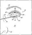
- FIGS. 5A and 5B the device 10 is used in a method for treating ocular disorders of the eye 15 . While the method for treating ocular disorder will be described with respect to device 10 , it will be appreciated that the device 110 (see FIG. 2 ) may be similarly used.
- FIGS. 5A and 5B generally show a portion of a face 50 having a nose 52 , an eyebrow 54 , and the eye 15 .
- the eye 15 described herein generally includes, but is not limited to, an eyeball 56 including a cornea 58 , an upper eyelid margin 60 , a lower eyelid margin 62 , and a plurality of eyelashes 64 .
- the device 10 is the swab 14 operably connected to the mechanical drive unit 12 thereby creating the electromechanical device 10 for use in removing debris deposited on at least one of either the upper eyelid margin 60 or the lower eyelid margin 62 .
- an instrument 22 is removably secured to the chuck 132 , after which time, the electromechanical device 10 may be powered on and set to a desirable speed by the operator; thereby, the operator effects movement of the swab 14 relative to the electromechanical device 10 .
- Such movement may include, but is not limited to, reciprocating the swab 14 as shown by arrows 38 a , rotating the swab 14 as shown by arrow 38 b , and/or vibrating the swab 14 as shown by lines 38 c .
- the swab 14 is positioned near the eyeball 56 and along either one of the upper or lower eyelid margins 60 , 62 for treatment. In the exemplary embodiment as shown in FIGS.
- the swab 14 moves with constant movement relative to the electromechanical device 10 while near the eyeball 56 .
- the operator preferably targets the debris present on the eye 15 with the swab 14 of the electromechanical device 10 .
- the debris may be targeted by visually inspecting the eye 15 with or without the aid of a magnification device. Once the debris is targeted, the swab 14 contacts the portion of the eye 15 that includes the debris.
- the debris may be removably attached on either the upper and lower eyelid margins 60 , 62 or the plurality of eyelashes 64 . Thereby, upon contacting the portion of the eye 15 with the debris, the swab 14 impacts the debris to remove the debris from the eye 15 .
- a liquid solution configured to loosen the debris may be absorbed within the swab 14 to further aid in removing the debris from the eye 15 and/or minimizing irritation to the eye 15 . It will be appreciated that any liquid solution sufficiently capable of loosening the debris to further aid in removing the debris may be so used.
- the electromechanical device 10 operably drives the swab 14 to break the debris free from either of the upper or lower eyelid margins 60 , 62 .
- Further treatment may be performed to enhance the effects of the debris removal by helping to improve healing and reducing further infection of the eye 15 .
- Such treatment may include scrubbing, exfoliating, or buffing the eyelid margin or un-roofing a meibomian gland 66 with the swab 14 .
- the cornea 58 of the eye 15 is directed away from the position of the swab 14 to minimize contacting the swab 14 to the cornea 58 during treatment.
- the eyeball 56 directs the cornea 58 upward, thereby bringing the cornea 58 closer to the upper eyelid margin 60 than the lower eyelid margin 62 .
- the eyeball 56 directs the cornea 58 downward, thereby being closer to the lower eyelid margin 62 than the upper eyelid margin 60 .
- accessing the portion of the eye 15 with the debris may be accomplished without further moving or lifting other portions of the eye 15 .
- the operator may use a hand 68 , or similar gripping device, to move or lift a portion of the eye 15 , such as lifting the upper or lower eyelid margin 60 , 62 from against the eyeball 56 , to improve access to the debris.
- Such lifting may be particularly beneficial for improving access to the meibomian gland 66 .
- FIGS. 5A and 5B are merely exemplary embodiments showing both non-assisted access and assisted access of the swab 14 to the eye 15 respectively.
- the method of treating the ocular disorder may be repeated as directed by a physician or patient in order to sufficiently remedy the disorder.
- the physician may direct the patient to visit the physician in periodic intervals for treating the ocular disorder with the electromechanical device 10 . More specifically, the physician directs the patient to visit the physician in periodic monthly or weekly intervals so that the physician may treat the patient.
- periodic intervals are treatments with the electromechanical device 10 once every month. It will be appreciated that any periodic interval of repeating the method of treating the ocular disorder with the electromechanical device 10 may be so used.
- the patient may treat his or her own ocular disorder with the electromechanical device 10 in periodic intervals.
- the physician repeats the method of treating the ocular disorder in periodic intervals with the electromechanical device 10 and the patient also treats the ocular disorder in between physician treatments using traditional treatments.
- This method of treating the ocular disorder with the electromechanical device 10 in treatments occurring in periodic intervals achieves superior removal of the debris compared to traditional treatments, because the periodic intervals act as reminders to the patient.
- the patient is less likely to forget to treat the ocular disorders once symptoms begin to subside, which may result in a resurgence of the disorder.
- the traditional treatments despite being less effective, may be performed regularly by the patient to further treat the ocular disorder in conjunction with physician treatments with the electromechanical device 10 .
- the physician or patient treats the ocular disorder until the ocular disorder is sufficiently healed and thereafter to prevent a recurrence of the disorder.
- sufficiently healed refers to the dissipation of inflammation and/or discomfort related to the debris within the eye 15 at which time the treatments by the physician may decrease in frequency, but may continue in periodic intervals during home treatment by the patient.
- the physician or patient may remove the used instrument 22 from the chuck 32 and dispose of the used instrument 22 .
- the used instrument 22 may then be replaced with a new instrument 22 for future treatments.
- the method of treating the ocular disorder may resume as the physician or patient desires. However, the treatment may be required in periodic intervals throughout the remainder of the patient's life.
Abstract
Description
Claims (18)
Priority Applications (3)
| Application Number | Priority Date | Filing Date | Title |
|---|---|---|---|
| US16/590,228 US11083621B2 (en) | 2012-07-24 | 2019-10-01 | Instrument for treating an ocular disorder |
| US17/364,321 US20220125636A1 (en) | 2012-07-24 | 2021-06-30 | Method and device for treating an ocular disorder |
| US18/116,005 US20230201032A1 (en) | 2012-07-24 | 2023-03-01 | Method and device for treating an ocular disorder |
Applications Claiming Priority (4)
| Application Number | Priority Date | Filing Date | Title |
|---|---|---|---|
| US13/556,729 US9039718B2 (en) | 2012-07-24 | 2012-07-24 | Method and device for treating an ocular disorder |
| US13/949,365 US10821022B2 (en) | 2012-07-24 | 2013-07-24 | Instrument for treating an ocular disorder |
| US16/352,758 US10449087B2 (en) | 2012-07-24 | 2019-03-13 | Instrument for treating an ocular disorder |
| US16/590,228 US11083621B2 (en) | 2012-07-24 | 2019-10-01 | Instrument for treating an ocular disorder |
Related Parent Applications (1)
| Application Number | Title | Priority Date | Filing Date |
|---|---|---|---|
| US16/352,758 Continuation US10449087B2 (en) | 2012-07-24 | 2019-03-13 | Instrument for treating an ocular disorder |
Related Child Applications (1)
| Application Number | Title | Priority Date | Filing Date |
|---|---|---|---|
| US17/364,321 Continuation US20220125636A1 (en) | 2012-07-24 | 2021-06-30 | Method and device for treating an ocular disorder |
Publications (2)
| Publication Number | Publication Date |
|---|---|
| US20200030146A1 US20200030146A1 (en) | 2020-01-30 |
| US11083621B2 true US11083621B2 (en) | 2021-08-10 |
Family
ID=48917721
Family Applications (5)
| Application Number | Title | Priority Date | Filing Date |
|---|---|---|---|
| US13/949,365 Active US10821022B2 (en) | 2012-07-24 | 2013-07-24 | Instrument for treating an ocular disorder |
| US16/352,758 Active US10449087B2 (en) | 2012-07-24 | 2019-03-13 | Instrument for treating an ocular disorder |
| US16/590,228 Active US11083621B2 (en) | 2012-07-24 | 2019-10-01 | Instrument for treating an ocular disorder |
| US17/364,321 Pending US20220125636A1 (en) | 2012-07-24 | 2021-06-30 | Method and device for treating an ocular disorder |
| US18/116,005 Pending US20230201032A1 (en) | 2012-07-24 | 2023-03-01 | Method and device for treating an ocular disorder |
Family Applications Before (2)
| Application Number | Title | Priority Date | Filing Date |
|---|---|---|---|
| US13/949,365 Active US10821022B2 (en) | 2012-07-24 | 2013-07-24 | Instrument for treating an ocular disorder |
| US16/352,758 Active US10449087B2 (en) | 2012-07-24 | 2019-03-13 | Instrument for treating an ocular disorder |
Family Applications After (2)
| Application Number | Title | Priority Date | Filing Date |
|---|---|---|---|
| US17/364,321 Pending US20220125636A1 (en) | 2012-07-24 | 2021-06-30 | Method and device for treating an ocular disorder |
| US18/116,005 Pending US20230201032A1 (en) | 2012-07-24 | 2023-03-01 | Method and device for treating an ocular disorder |
Country Status (10)
| Country | Link |
|---|---|
| US (5) | US10821022B2 (en) |
| JP (1) | JP6312671B2 (en) |
| KR (1) | KR20150061632A (en) |
| CN (1) | CN104837443B (en) |
| AU (1) | AU2013295781B2 (en) |
| CA (1) | CA2873219C (en) |
| EA (1) | EA031138B1 (en) |
| IL (1) | IL235493B (en) |
| IN (1) | IN2015DN00824A (en) |
| WO (1) | WO2014018651A1 (en) |
Families Citing this family (14)
| Publication number | Priority date | Publication date | Assignee | Title |
|---|---|---|---|---|
| AU2013295781B2 (en) | 2012-07-24 | 2017-10-05 | Blephex, Llc | Device for treating an ocular disorder |
| WO2014031857A2 (en) | 2012-08-22 | 2014-02-27 | Tearscience, Inc. | Apparatuses and methods for diagnosing and/or treating lipid transport deficiency in ocular tear films, and related components and devices |
| USD732163S1 (en) * | 2013-07-24 | 2015-06-16 | Blephex, Llc | Instrument for treating an ocular disorder |
| US20150125813A1 (en) * | 2013-11-05 | 2015-05-07 | Dentek Oral Care, Inc. | Topical Anesthetic Applicator, and Method for Numbing a Dental Area |
| US10314763B2 (en) | 2013-12-31 | 2019-06-11 | Teeny Clean, Llc | Eyelid care appliance |
| EP3470027B1 (en) * | 2015-01-30 | 2022-11-30 | Rynerson, James, M. | Instruments for removing debris from an eye |
| EP3362013A1 (en) | 2015-10-16 | 2018-08-22 | Rynerson, James, M. | Energetic device for treating an eye disorder |
| US10251634B2 (en) * | 2016-02-19 | 2019-04-09 | Brett Foxman | Scleral depressor |
| KR101774161B1 (en) * | 2016-06-27 | 2017-09-01 | 동국대학교 산학협력단 | Fusion device for image diagnosis and treatment of meibomian gland dysfunction |
| US10404203B2 (en) | 2017-12-18 | 2019-09-03 | Myco Industries, Inc. | Adapter kit for a battery powered rotary tool, a rotary tool, and a rotary swab |
| US11141348B2 (en) * | 2018-02-26 | 2021-10-12 | Olympic Ophthalmics, Inc. | Treatment methods using handheld devices for disorders |
| DK180082B1 (en) * | 2018-05-04 | 2020-04-01 | Julian Kim | An eye treatment device. |
| CN108836623B (en) * | 2018-06-29 | 2024-03-19 | 惠州华阳医疗器械有限公司 | Medical spherical sponge eye brush and preparation method thereof |
| KR102576162B1 (en) * | 2021-04-28 | 2023-09-07 | 주식회사 엠에스씨랩 | detachment device of vitreous cortex for ophthalmic surgery |
Citations (76)
| Publication number | Priority date | Publication date | Assignee | Title |
|---|---|---|---|---|
| US111265A (en) | 1871-01-24 | Improvement in rock-drills | ||
| US1100504A (en) | 1913-07-22 | 1914-06-16 | Herbert Othro Taft | Jack-spool and fastener. |
| US1554317A (en) | 1923-11-06 | 1925-09-22 | Emma A Worthing | Handle fastening |
| US1707353A (en) | 1927-06-25 | 1929-04-02 | Speakman Co | Valve-handle connection |
| US1832554A (en) | 1928-10-08 | 1931-11-17 | Adolph M Holstein | Knob construction |
| US2006539A (en) | 1933-07-21 | 1935-07-02 | D4 Drug Company Ltd | Swab |
| US2546061A (en) | 1948-01-19 | 1951-03-20 | Beauvais Pierre De | Socket contact with resilient inserts |
| US2766650A (en) | 1954-11-05 | 1956-10-16 | Ottavio A Capra | Heel plate assembly for a removable jaw wrench |
| US2766471A (en) | 1954-03-16 | 1956-10-16 | William H Mckenzie | Carboloy tipped double end inserted scraper and handle |
| US3029672A (en) | 1958-12-30 | 1962-04-17 | Atlas Copco Ab | Pawl and ratchet mechanisms, particularly for pneumatic percussion tools |
| US3507508A (en) | 1968-07-24 | 1970-04-21 | Edward N Andrews | Toolholder bushing |
| US3517754A (en) | 1968-10-16 | 1970-06-30 | Ingersoll Rand Co | Rock drill bit drive |
| USD262739S (en) | 1978-08-28 | 1982-01-19 | Bristol-Myers Company | Combined syringe barrel, needle hood and cap therefor |
| USD286438S (en) | 1983-05-16 | 1986-10-28 | Acufex Microsurgical Inc. | Surgical obturator |
| CN86204490U (en) | 1986-07-02 | 1987-04-01 | 中国人民解放军空军石家庄医院 | Suction device for corneal foreign body |
| US4778457A (en) | 1986-11-06 | 1988-10-18 | York Kenneth K | Disposable applicator |
| US4838851A (en) | 1986-11-26 | 1989-06-13 | Shabo Alan L | Applicator and package therefor |
| US4883454A (en) | 1987-09-04 | 1989-11-28 | Sol Hamburg | Eyelid and anterior orbit swab |
| USD306347S (en) | 1986-11-19 | 1990-02-27 | Smithkline Beckman Corporation | Delayed action dosage unit for releasing medicaments or the like in ruminants |
| US4913682A (en) | 1988-04-14 | 1990-04-03 | Alan Shabo | Applicator and package therefor |
| US4955896A (en) | 1985-09-27 | 1990-09-11 | Freeman Jerre M | Universal medical forcep tool |
| US5176694A (en) | 1989-10-02 | 1993-01-05 | Price James A | Eye spud |
| JPH06261839A (en) | 1993-03-08 | 1994-09-20 | Mizuki Ono | Motor-driven earpick |
| US5456265A (en) | 1993-09-28 | 1995-10-10 | Yim; Duck S. | Endocervical brush assembly and method for obtaining tissue samples |
| US5458427A (en) | 1991-05-24 | 1995-10-17 | Simond; Ludger | Telescopic tubular splined assembly |
| US5498077A (en) | 1993-10-29 | 1996-03-12 | F.A.S. | Adjustable coupling device for driving the stirrer rod shank of stirring devices, in paint stirring machines |
| WO1996033676A1 (en) | 1995-04-28 | 1996-10-31 | Rainin Edgar A | Surgical abrading device |
| US5588497A (en) | 1993-10-28 | 1996-12-31 | Galison Drilling (Proprietary) Limited | Mounting drill buttons |
| US5632756A (en) | 1994-12-20 | 1997-05-27 | Kruglick; Kenneth | Ear cleaning device utilizing bulbous banded cage |
| US5690618A (en) | 1995-02-22 | 1997-11-25 | Mark Timothy Smith | Electronic syringe |
| JPH10108801A (en) | 1996-10-07 | 1998-04-28 | Kiyoshi Yamaura | Electric ear inside cleaner |
| USD401332S (en) | 1996-08-21 | 1998-11-17 | Applied Medical Technology, Inc. | Decompression tube |
| US5904390A (en) | 1994-05-12 | 1999-05-18 | Penda Corporation | Bedliner with pockets for load restraint |
| US5974615A (en) | 1996-07-10 | 1999-11-02 | Braun Aktiengesellschaft | Rotary electric toothbrush with stroke-type bristle movement |
| US6036198A (en) | 1999-04-01 | 2000-03-14 | Kramer; Hy | Coupling for attaching a tool to a chuck |
| CA2257040A1 (en) | 1996-04-22 | 2000-06-24 | Mark Peritz | Drill for interchangeable use on a screwdriver |
| US6116900A (en) | 1997-11-17 | 2000-09-12 | Lumachem, Inc. | Binary energizer and peroxide delivery system for dental bleaching |
| CN2538310Y (en) | 2002-02-28 | 2003-03-05 | 李秋明 | Non-magnetic extractor for intra-ocular foreign body |
| US6536066B2 (en) | 2001-07-25 | 2003-03-25 | Pulse Innovations Inc. | Toothbrush oscillating head |
| US20040067098A1 (en) | 2002-10-04 | 2004-04-08 | Frank Sun | Support system |
| US20040172035A1 (en) | 2003-02-27 | 2004-09-02 | C.G.M. S.P.A. | Tool for expanding the hole formed in the bone, in particular for installing an endosseous dental implant |
| US20050132513A1 (en) | 2002-01-31 | 2005-06-23 | Colgate-Palmolive Company | Powered toothbrush |
| US20060116355A1 (en) | 2004-11-26 | 2006-06-01 | Van Breen Eduard T | Eye care kit for treating periocular disease |
| US20070016255A1 (en) | 2005-07-18 | 2007-01-18 | Korb Donald R | Method and apparatus for treating meibomian gland dysfunction |
| US20070049860A1 (en) | 2005-09-01 | 2007-03-01 | Robert Seminara | Apparatus and method for using a surgical instrument with an expandable sponge |
| US20070060988A1 (en) * | 2005-07-18 | 2007-03-15 | Grenon Stephen M | Melting meibomian gland obstructions |
| US20070231353A1 (en) | 2004-03-31 | 2007-10-04 | Advanced Vision Research, Inc. | Compositons and methods for maintaining eyelid hygiene |
| US7384405B2 (en) | 2004-09-10 | 2008-06-10 | Rhoades Dean L | Oxygenating cosmetic instrument having various numbers of heads |
| US20080188877A1 (en) | 2007-02-05 | 2008-08-07 | Hickingbotham Dyson W | Instruments For Removing an Object From the Eye |
| US20080221533A1 (en) | 2007-03-09 | 2008-09-11 | Anthem Orthopaedics Llc | Implantable device with bioabsorbable layer, kit and method for use therewith, and apparatus for preparing same |
| US20080260563A1 (en) | 2004-05-07 | 2008-10-23 | Viktor Refenius | Pumps |
| CN201168118Y (en) | 2007-11-08 | 2008-12-24 | 艾力江·买买提 | Multifunctional cleaner for ear and tooth |
| USD588697S1 (en) | 2007-05-22 | 2009-03-17 | San Diego Swiss Machining, Inc. | Ultrasonic dental tip |
| USD589620S1 (en) | 2007-05-22 | 2009-03-31 | San Diego Swiss Maching, Inc. | Ultrasonic dental tip |
| US20090112242A1 (en) | 2007-10-24 | 2009-04-30 | Highplus International Co., Ltd. | Ear curette |
| US20090124985A1 (en) * | 2007-06-13 | 2009-05-14 | Erik John Hasenoehrl | Skin treatment device |
| WO2009066077A1 (en) | 2007-11-21 | 2009-05-28 | Innovative Treatment Solutions Limited | Apparatus and method of massage |
| CN201362154Y (en) | 2009-03-20 | 2009-12-16 | 孙加慧 | Device utilizing automobile tail gas to carry out secondary heating on carriages of passenger/cargo vehicles |
| CN201505215U (en) | 2009-09-30 | 2010-06-16 | 刘娟 | Foreign matter taking and removing device for clearing the corneal foreign matter |
| WO2010149959A1 (en) | 2009-06-24 | 2010-12-29 | Innovative Treatment Solutions Ltd | Improved massage apparatus and method of use |
| CN201692153U (en) | 2010-05-31 | 2011-01-05 | 张正平 | Electric earpick for leisure |
| US20110144562A1 (en) | 2009-12-14 | 2011-06-16 | Alcon Research, Ltd. | Localized Pharmacological Treatment of Ocular Tissue Using High-Intensity Pulsed Electrical Fields |
| US20110160635A1 (en) | 2009-12-24 | 2011-06-30 | Baschnagel Robert J | Cotton balls, cotton swabs and cotton swab holder |
| USD645140S1 (en) | 2010-02-03 | 2011-09-13 | 3M Innovative Properties Company | Dental syringe |
| US20120065556A1 (en) | 2010-09-15 | 2012-03-15 | Smith Walton F | Device and method for stimulating the meibomian glands of the eyelid |
| WO2012092320A2 (en) | 2010-12-29 | 2012-07-05 | Nichamin Louis D | Eye treatment |
| US20130058710A1 (en) | 2011-09-02 | 2013-03-07 | Roy Fan | Rotating Drive Shaft Coupling |
| US20130081518A1 (en) | 2011-09-30 | 2013-04-04 | Eric Scheid | Extraction device and method |
| WO2014018651A1 (en) | 2012-07-24 | 2014-01-30 | Rynerson James M | Device for treating an ocular disorder |
| US20140031845A1 (en) | 2012-07-24 | 2014-01-30 | James M. Rynerson | Method and device for treating an ocular disorder |
| USD701308S1 (en) | 2013-03-15 | 2014-03-18 | James K. Brannon | Burr |
| USD701304S1 (en) | 2011-09-13 | 2014-03-18 | Neomed, Inc. | Extension set adapter |
| USD705426S1 (en) | 2011-11-08 | 2014-05-20 | Intelligent Dental Innovations, Inc. | Tool base for dental endodontic tips |
| US20140214062A1 (en) | 2012-07-24 | 2014-07-31 | James RYNERSON | Method and device for treating an ocular disorder |
| US20140221908A1 (en) | 2011-07-01 | 2014-08-07 | Vanderbilt University | Surfactant ported device for treatment of blepharitis and applications of same |
| US20140249509A1 (en) * | 2012-03-29 | 2014-09-04 | Cxl Ophthalmics, Llc | Ophthalmic treatment solution delivery devices and delivery augmentation methods |
Family Cites Families (5)
| Publication number | Priority date | Publication date | Assignee | Title |
|---|---|---|---|---|
| US7981145B2 (en) * | 2005-07-18 | 2011-07-19 | Tearscience Inc. | Treatment of meibomian glands |
| CN201530418U (en) | 2009-10-15 | 2010-07-21 | 中国重汽集团济南动力有限公司 | Heavy type automobile vehicle frame crossbeam assembly |
| CN201692154U (en) * | 2010-06-09 | 2011-01-05 | 殷建斌 | Portable earpick |
| US20130046367A1 (en) * | 2011-08-18 | 2013-02-21 | Willie Ying-Wei Chen | Lipid Removal Device for Treating Blepharitis (Meibomian Gland Dysfunction) |
| EP2753275A4 (en) * | 2011-09-08 | 2015-05-27 | Biolase Inc | Methods for treating eye conditions |
-
2013
- 2013-07-24 AU AU2013295781A patent/AU2013295781B2/en active Active
- 2013-07-24 CN CN201380049077.1A patent/CN104837443B/en active Active
- 2013-07-24 KR KR1020157004464A patent/KR20150061632A/en not_active Application Discontinuation
- 2013-07-24 US US13/949,365 patent/US10821022B2/en active Active
- 2013-07-24 CA CA2873219A patent/CA2873219C/en active Active
- 2013-07-24 EA EA201590259A patent/EA031138B1/en not_active IP Right Cessation
- 2013-07-24 JP JP2015524423A patent/JP6312671B2/en active Active
- 2013-07-24 WO PCT/US2013/051850 patent/WO2014018651A1/en active Application Filing
-
2014
- 2014-11-04 IL IL235493A patent/IL235493B/en active IP Right Grant
-
2015
- 2015-02-02 IN IN824DEN2015 patent/IN2015DN00824A/en unknown
-
2019
- 2019-03-13 US US16/352,758 patent/US10449087B2/en active Active
- 2019-10-01 US US16/590,228 patent/US11083621B2/en active Active
-
2021
- 2021-06-30 US US17/364,321 patent/US20220125636A1/en active Pending
-
2023
- 2023-03-01 US US18/116,005 patent/US20230201032A1/en active Pending
Patent Citations (83)
| Publication number | Priority date | Publication date | Assignee | Title |
|---|---|---|---|---|
| US111265A (en) | 1871-01-24 | Improvement in rock-drills | ||
| US1100504A (en) | 1913-07-22 | 1914-06-16 | Herbert Othro Taft | Jack-spool and fastener. |
| US1554317A (en) | 1923-11-06 | 1925-09-22 | Emma A Worthing | Handle fastening |
| US1707353A (en) | 1927-06-25 | 1929-04-02 | Speakman Co | Valve-handle connection |
| US1832554A (en) | 1928-10-08 | 1931-11-17 | Adolph M Holstein | Knob construction |
| US2006539A (en) | 1933-07-21 | 1935-07-02 | D4 Drug Company Ltd | Swab |
| US2546061A (en) | 1948-01-19 | 1951-03-20 | Beauvais Pierre De | Socket contact with resilient inserts |
| US2766471A (en) | 1954-03-16 | 1956-10-16 | William H Mckenzie | Carboloy tipped double end inserted scraper and handle |
| US2766650A (en) | 1954-11-05 | 1956-10-16 | Ottavio A Capra | Heel plate assembly for a removable jaw wrench |
| US3029672A (en) | 1958-12-30 | 1962-04-17 | Atlas Copco Ab | Pawl and ratchet mechanisms, particularly for pneumatic percussion tools |
| US3507508A (en) | 1968-07-24 | 1970-04-21 | Edward N Andrews | Toolholder bushing |
| US3517754A (en) | 1968-10-16 | 1970-06-30 | Ingersoll Rand Co | Rock drill bit drive |
| USD262739S (en) | 1978-08-28 | 1982-01-19 | Bristol-Myers Company | Combined syringe barrel, needle hood and cap therefor |
| USD286438S (en) | 1983-05-16 | 1986-10-28 | Acufex Microsurgical Inc. | Surgical obturator |
| US4955896A (en) | 1985-09-27 | 1990-09-11 | Freeman Jerre M | Universal medical forcep tool |
| CN86204490U (en) | 1986-07-02 | 1987-04-01 | 中国人民解放军空军石家庄医院 | Suction device for corneal foreign body |
| US4778457A (en) | 1986-11-06 | 1988-10-18 | York Kenneth K | Disposable applicator |
| USD306347S (en) | 1986-11-19 | 1990-02-27 | Smithkline Beckman Corporation | Delayed action dosage unit for releasing medicaments or the like in ruminants |
| US4838851A (en) | 1986-11-26 | 1989-06-13 | Shabo Alan L | Applicator and package therefor |
| US4883454A (en) | 1987-09-04 | 1989-11-28 | Sol Hamburg | Eyelid and anterior orbit swab |
| US4913682A (en) | 1988-04-14 | 1990-04-03 | Alan Shabo | Applicator and package therefor |
| US5176694A (en) | 1989-10-02 | 1993-01-05 | Price James A | Eye spud |
| US5458427A (en) | 1991-05-24 | 1995-10-17 | Simond; Ludger | Telescopic tubular splined assembly |
| JPH06261839A (en) | 1993-03-08 | 1994-09-20 | Mizuki Ono | Motor-driven earpick |
| US5456265A (en) | 1993-09-28 | 1995-10-10 | Yim; Duck S. | Endocervical brush assembly and method for obtaining tissue samples |
| US5588497A (en) | 1993-10-28 | 1996-12-31 | Galison Drilling (Proprietary) Limited | Mounting drill buttons |
| US5498077A (en) | 1993-10-29 | 1996-03-12 | F.A.S. | Adjustable coupling device for driving the stirrer rod shank of stirring devices, in paint stirring machines |
| US5904390A (en) | 1994-05-12 | 1999-05-18 | Penda Corporation | Bedliner with pockets for load restraint |
| US5632756A (en) | 1994-12-20 | 1997-05-27 | Kruglick; Kenneth | Ear cleaning device utilizing bulbous banded cage |
| US5690618A (en) | 1995-02-22 | 1997-11-25 | Mark Timothy Smith | Electronic syringe |
| WO1996033676A1 (en) | 1995-04-28 | 1996-10-31 | Rainin Edgar A | Surgical abrading device |
| CA2257040A1 (en) | 1996-04-22 | 2000-06-24 | Mark Peritz | Drill for interchangeable use on a screwdriver |
| US5974615A (en) | 1996-07-10 | 1999-11-02 | Braun Aktiengesellschaft | Rotary electric toothbrush with stroke-type bristle movement |
| USD401332S (en) | 1996-08-21 | 1998-11-17 | Applied Medical Technology, Inc. | Decompression tube |
| JPH10108801A (en) | 1996-10-07 | 1998-04-28 | Kiyoshi Yamaura | Electric ear inside cleaner |
| US6116900A (en) | 1997-11-17 | 2000-09-12 | Lumachem, Inc. | Binary energizer and peroxide delivery system for dental bleaching |
| US6036198A (en) | 1999-04-01 | 2000-03-14 | Kramer; Hy | Coupling for attaching a tool to a chuck |
| US6536066B2 (en) | 2001-07-25 | 2003-03-25 | Pulse Innovations Inc. | Toothbrush oscillating head |
| US20050132513A1 (en) | 2002-01-31 | 2005-06-23 | Colgate-Palmolive Company | Powered toothbrush |
| CN2538310Y (en) | 2002-02-28 | 2003-03-05 | 李秋明 | Non-magnetic extractor for intra-ocular foreign body |
| US20040067098A1 (en) | 2002-10-04 | 2004-04-08 | Frank Sun | Support system |
| US20040172035A1 (en) | 2003-02-27 | 2004-09-02 | C.G.M. S.P.A. | Tool for expanding the hole formed in the bone, in particular for installing an endosseous dental implant |
| US20070231353A1 (en) | 2004-03-31 | 2007-10-04 | Advanced Vision Research, Inc. | Compositons and methods for maintaining eyelid hygiene |
| US20080260563A1 (en) | 2004-05-07 | 2008-10-23 | Viktor Refenius | Pumps |
| US7384405B2 (en) | 2004-09-10 | 2008-06-10 | Rhoades Dean L | Oxygenating cosmetic instrument having various numbers of heads |
| US20060116355A1 (en) | 2004-11-26 | 2006-06-01 | Van Breen Eduard T | Eye care kit for treating periocular disease |
| US20100256552A1 (en) | 2005-07-18 | 2010-10-07 | Tearscience, Inc. | Method and apparatus for treating meibomian gland dysfunction |
| US20070016255A1 (en) | 2005-07-18 | 2007-01-18 | Korb Donald R | Method and apparatus for treating meibomian gland dysfunction |
| US20070060988A1 (en) * | 2005-07-18 | 2007-03-15 | Grenon Stephen M | Melting meibomian gland obstructions |
| US20110137214A1 (en) | 2005-07-18 | 2011-06-09 | Tearscience, Inc. | Method and apparatus for treating gland dysfunction |
| US20070049860A1 (en) | 2005-09-01 | 2007-03-01 | Robert Seminara | Apparatus and method for using a surgical instrument with an expandable sponge |
| US20080188877A1 (en) | 2007-02-05 | 2008-08-07 | Hickingbotham Dyson W | Instruments For Removing an Object From the Eye |
| US20080221533A1 (en) | 2007-03-09 | 2008-09-11 | Anthem Orthopaedics Llc | Implantable device with bioabsorbable layer, kit and method for use therewith, and apparatus for preparing same |
| USD588697S1 (en) | 2007-05-22 | 2009-03-17 | San Diego Swiss Machining, Inc. | Ultrasonic dental tip |
| USD589620S1 (en) | 2007-05-22 | 2009-03-31 | San Diego Swiss Maching, Inc. | Ultrasonic dental tip |
| US20090124985A1 (en) * | 2007-06-13 | 2009-05-14 | Erik John Hasenoehrl | Skin treatment device |
| US20090112242A1 (en) | 2007-10-24 | 2009-04-30 | Highplus International Co., Ltd. | Ear curette |
| CN201168118Y (en) | 2007-11-08 | 2008-12-24 | 艾力江·买买提 | Multifunctional cleaner for ear and tooth |
| WO2009066077A1 (en) | 2007-11-21 | 2009-05-28 | Innovative Treatment Solutions Limited | Apparatus and method of massage |
| CN201362154Y (en) | 2009-03-20 | 2009-12-16 | 孙加慧 | Device utilizing automobile tail gas to carry out secondary heating on carriages of passenger/cargo vehicles |
| US9675516B2 (en) | 2009-06-24 | 2017-06-13 | Innovative Treatment Solutions Ltd. | Massage apparatus and method of use |
| WO2010149959A1 (en) | 2009-06-24 | 2010-12-29 | Innovative Treatment Solutions Ltd | Improved massage apparatus and method of use |
| CN201505215U (en) | 2009-09-30 | 2010-06-16 | 刘娟 | Foreign matter taking and removing device for clearing the corneal foreign matter |
| US20110144562A1 (en) | 2009-12-14 | 2011-06-16 | Alcon Research, Ltd. | Localized Pharmacological Treatment of Ocular Tissue Using High-Intensity Pulsed Electrical Fields |
| US20110160635A1 (en) | 2009-12-24 | 2011-06-30 | Baschnagel Robert J | Cotton balls, cotton swabs and cotton swab holder |
| USD645140S1 (en) | 2010-02-03 | 2011-09-13 | 3M Innovative Properties Company | Dental syringe |
| CN201692153U (en) | 2010-05-31 | 2011-01-05 | 张正平 | Electric earpick for leisure |
| US20120065556A1 (en) | 2010-09-15 | 2012-03-15 | Smith Walton F | Device and method for stimulating the meibomian glands of the eyelid |
| US20130331768A1 (en) * | 2010-12-29 | 2013-12-12 | Louis D. Nichamin | Eye treatment |
| WO2012092320A2 (en) | 2010-12-29 | 2012-07-05 | Nichamin Louis D | Eye treatment |
| US20140221908A1 (en) | 2011-07-01 | 2014-08-07 | Vanderbilt University | Surfactant ported device for treatment of blepharitis and applications of same |
| US20130058710A1 (en) | 2011-09-02 | 2013-03-07 | Roy Fan | Rotating Drive Shaft Coupling |
| USD701304S1 (en) | 2011-09-13 | 2014-03-18 | Neomed, Inc. | Extension set adapter |
| US20130081518A1 (en) | 2011-09-30 | 2013-04-04 | Eric Scheid | Extraction device and method |
| USD705426S1 (en) | 2011-11-08 | 2014-05-20 | Intelligent Dental Innovations, Inc. | Tool base for dental endodontic tips |
| US20140249509A1 (en) * | 2012-03-29 | 2014-09-04 | Cxl Ophthalmics, Llc | Ophthalmic treatment solution delivery devices and delivery augmentation methods |
| US20140214062A1 (en) | 2012-07-24 | 2014-07-31 | James RYNERSON | Method and device for treating an ocular disorder |
| US20140052164A1 (en) | 2012-07-24 | 2014-02-20 | RySurg, LLC | Instrument for treating an ocular disorder |
| US20140031845A1 (en) | 2012-07-24 | 2014-01-30 | James M. Rynerson | Method and device for treating an ocular disorder |
| US9039718B2 (en) | 2012-07-24 | 2015-05-26 | Blephex, Llc | Method and device for treating an ocular disorder |
| WO2014018651A1 (en) | 2012-07-24 | 2014-01-30 | Rynerson James M | Device for treating an ocular disorder |
| US20190209373A1 (en) | 2012-07-24 | 2019-07-11 | Blephex, Llc | Instrument for treating an ocular disorder |
| USD701308S1 (en) | 2013-03-15 | 2014-03-18 | James K. Brannon | Burr |
Non-Patent Citations (118)
| Title |
|---|
| "Connector standard sheets." Wikipedia. < http://en.wikipedia.org/wiki/IEC_60320. Accessed Sep. 13, 2018. |
| Advertising material for the AlgerBrush II. Bates No. PPM000709-PPM000710. 2 pages. |
| Alger Equipment Company, Algerbrush II, Introduction, Product Info, About Us, FAQ's, [https://web.archive.org/web/20101121065649/http://www.algercompany.co] (2009)]; [https://web.archive/org/web/20100103204839/http://www.algercompany.co](2009); [https://web.archive.org/web/20100817072535/http://www/algercompany.co] (2009); [https://web.archiveorg/web20101030135414/http://www.algercompany.co] (2009); [https://web.archive.org/web/20101029151415/http://www.algercompany.co] (2009); and [https://web/archive.org/web/20101030135409/http://]. |
| AlgerBrush II device. Bates No. PPM000714-PPM000716. 3 pages. (Oct. 11, 2018). |
| AlgerBrush II device. Bates No. PPM002763. 1 page. (Oct. 11, 2018). |
| AlgerBrush II device. Bates No. PPM002764. 1 page. (Oct. 11, 2018). |
| Algerbrush II Quick Reference Catalog, [cited Oct. 2012]. Available from [www.rheinmedical.com/wpcontent/uploads/2012/10/AlgerbrushCatalog1333AHBC.pdf]. |
| Australian Patent Application No. 2013295781 Office Action dated Sep. 20, 2017. |
| Blephex Advertisement. Bates No. B000584. 1 page. (Oct. 11, 2018). |
| Blephex LLC v. Myco Industries, Inc. and John R. Choate, Case No. 2:19-cv-13089-DML-APP, Exhibit 1, Invalidity Contentions for U.S. Pat. No. 10,449,087, filed Jun. 1, 2020, 21 pages. |
| Blephex LLC v. Myco Industries, Inc. and John R. Choate, Case No. 2:19-cv-13089-DML-APP, Exhibit 2, Invalidity Contentions for U.S. Pat. No. 10,449,087, filed Jun. 1, 2020, 30 pages. |
| Blephex LLC v. Myco Industries, Inc. and John R. Choate, Case No. 2:19-cv-13089-DML-APP, Exhibit 3, Invalidity Contentions for U.S. Pat. No. 10,449,087, filed Jun. 1, 2020, 20 pages. |
| Blephex LLC v. Myco Industries, Inc. and John R. Choate, Case No. 2:19-cv-13089-DML-APP, Exhibit 4, Invalidity Contentions for U.S. Pat. No. 10,449,087, filed Jun. 1, 2020, 21 pages. |
| Blephex LLC v. Myco Industries, Inc. and John R. Choate, Case No. 2:19-cv-13089-DML-APP, Exhibit 5, Invalidity Contentions for U.S. Pat. No. 10,449,087, filed Jun. 1, 2020, 25 pages. |
| Blephex LLC v. Myco Industries, Inc. and John R. Choate, Case No. 2:19-cv-13089-DML-APP, Exhibit 6, Invalidity Contentions for U.S. Pat. No. 10,449,087, filed Jun. 1, 2020, 21 pages. |
| BlephEx LLC v. Myco Industries, Inc. and John R. Choate, Case No. 2:19-cv-13089-GAD-EAS, USDC, Eastern District of Michigan, Defendant's Disclosure of Invalidity Contentions, filed Jun. 1, 2020, 15 pages. |
| Blephex LLC v. Pain Point Medical Systems, Inc., d/b/ MiBo Medical Group Inc., Case No. 3:16-cv-00410N, USDC, Northern District of Texas, Dallas Division, Defendant's Amended Invalidity Contentions, filed Oct. 11, 2018. 59 pages. |
| Blephex LLC v. Pain Point Medical Systems, Inc., d/b/a MiBo Medical Group Inc, Case No. 3:16-cv-00410N, USDC, Northern District of Texas, Dallas Division, Defendant's Invalidity Contentions, filed Jun. 24, 2016, 15 pages. |
| Blephex LLC v. Pain Point Medical Systems, Inc., d/b/a MiBo Medical Group Inc., Case No. 3:16-cv-00410N, USDC, Northern District of Texas, Dallas Division, Claim Construction Order, Issued Apr. 23, 2019. 12 pages. |
| Blephex Owner's Manual. Bates No. B000516-6000521. 6 pages. (Oct. 11, 2018). |
| BlephEx, LLC. v. Myco Industries, Inc. and John R. Choate. Civil Action No. 2:19-cv-13089. BlephEx, LLC's Motion for a Preliminary Injunction and Brief in Support. Nov. 7, 2019. |
| BlephEx, LLC. v. Myco Industries, Inc. and John R. Choate. Civil Action No. 2:19-cv-13089. BlephEx, LLC's Reply in Further Support of Motion for a Preliminary Injunction. Dec. 11, 2019. |
| BlephEx, LLC. v. Myco Industries, Inc. and John R. Choate. Civil Action No. 2:19-cv-13089. Declaration of Dr. James M. Rynerson in Support of BlephEx, LLC's Motion for a Preliminary Injunction. Nov. 7, 2019. |
| BlephEx, LLC. v. Myco Industries, Inc. and John R. Choate. Civil Action No. 2:19-cv-13089. Declaration of Matthew D. Robson in Support of BlephEx, LLC's Motion for a Preliminary Injunction. (Including the following Exhibits 1-30, 32-62). Nov. 7, 2019. |
| Brown et al.: Corneal Rust Removal by Electric Drill. British J. Ophthal. 59: 586-589 (1975). Bates No. PPM002809-PPM002813. 5 pages. |
| Canadian Patent Application No. 2,873,219 Office Action dated Mar. 21, 2016. |
| Chinese Patent Application No. 201380049077.1 Office Action dated Dec. 28, 2015 (English Translation Available). |
| Cotton swab. Bates No. PPM002765. 1 page. (Oct. 11, 2018). |
| Dremel brand rotary tool variable speed setting. Bates. No. PPM002770. 1 page. (Oct. 11, 2018). |
| Dremel brand rotary tool. Bates. No. PPM002766. 1 page. (Oct. 11, 2018). |
| Dremel brand rotary tool. Bates. No. PPM002767. 1 page. (Oct. 11, 2018). |
| Dremel brand rotary tool. Bates. No. PPM002768. 1 page. (Oct. 11, 2018). |
| Dremel brand rotary tool. Bates. No. PPM002769. 1 page. (Oct. 11, 2018). |
| Dremel Instructional Safety Manual. Bates No. PPM002771-PPM002793. 23 pages. (Oct. 11, 2018). |
| Dremel Quick Start Book. Bates No. PPM002794-PPM002804. 11 pages. (Oct. 11, 2018). |
| Eurasian Patent Application No. 201590259 Office Action dated Jul. 11, 2017 (English Translation Only). |
| Eurasian Patent Application No. 201590259 Office Action dated Oct. 4, 2016 (English Translation Available). |
| European search report with written opinion dated Mar. 26, 2019 for EP Application No. 18185867. |
| Exhibit 1: A true and correct U.S. Pat. No. 10,449,087. Nov. 7, 2019. |
| Exhibit 10: A true and correct excerpted Declaration of Dr. Penny Asbell submitted in support of BlephEx's proposed claim constructions, dated Aug. 29, 2019, from Myco Industries, Inc. v. BlephEx, LLC, 2:19-cv-10645-GAD-EAS (E.D. Mich.). Nov. 7, 2019. |
| Exhibit 11: A true and correct excerpted transcript of the Sep. 11, 2019 deposition of Dr. Steve Silberberg from Myco Industries, Inc. v. BlephEx, LLC, 2:19-cv-10645-GAD-EAS (E.D. Mich.). Nov. 7, 2019. |
| Exhibit 12: A true and correct Exhibit 14 to the Sep. 11, 2019 deposition of Dr. Steve Silberberg from Myco Industries, Inc. v. BlephEx, LLC, 2:19-cv-10645-GAD-EAS (E.D. Mich.). Nov. 7, 2019. |
| Exhibit 13: A true and correct excerpted Dorland's Illustrated Medical Dictionary, 30th Ed. (2003). Nov. 7, 2019. |
| Exhibit 14: A true and correct web page titled "What Makes up the Eyelid Margin?" dated Jan. 29, 2014 from the website of the American Academy of Ophthalmology. Nov. 7, 2019. |
| Exhibit 15: A true and correct web page titled "Eyelid margin" from the website of the American Academy of Ophthalmology. Nov. 7, 2019. |
| Exhibit 16: A true and correct article by Nelson et al. titled "The International Workshop on Meibomian Gland Dysfunction: Report of the Definition and Classification Subcommittee" by (2011) downloaded from iovs.arvojournals.org. Nov. 7, 2019. |
| Exhibit 17: A true and correct excerpted Chapter 1, Eyelid Anatomy, of a book by A. Biswas titled "Eyelid Tumors" (2014). Nov. 7, 2019. |
| Exhibit 18: A true and correct excerpted Myco's Answer to Amended Counterclaims from Myco Industries, Inc. v. BlephEx, LLC, 2:19-cv-10645-GAD-EAS, (E.D. Mich.). Nov. 7, 2019. |
| Exhibit 19: A true and correct document titled Owner's Manual for the BlephEx product. Nov. 7, 2019. |
| Exhibit 2: A true and correct excerpted prosecution history of U.S. Pat. No. 10,449,087. Nov. 7, 2019. |
| Exhibit 20: A true and correct document titled Instructions for Use for the AB Max product. Nov. 7, 2019. |
| Exhibit 21: A true and correct FDA web page relating to the AB Max product. Nov. 7, 2019. |
| Exhibit 22: A true and correct FDA web page describing the Product Code PYU. Nov. 7, 2019. |
| Exhibit 23: A true and correct Myco's web page www.ab-max.com/doctors/. Nov. 7, 2019. |
| Exhibit 24: A true and correct Myco's web page at www.alc-max.com/doctors/how-it-works/. Nov. 7, 2019. |
| Exhibit 25: A true and correct Myco's web page at www.ab-max.com/doctors/increase-profits/. Nov. 7, 2019. |
| Exhibit 26: A true and correct BlephEx's web page at www.blephex.com/doctors/index.php. Nov. 7, 2019. |
| Exhibit 27: A true and correct BlephEx's web page at www.blephex.com/doctors/index.php/how-does-blephex-work.html. Nov. 7, 2019. |
| Exhibit 28: A true and correct web page titled "BlephEx Treatment Offered in More Than 1,000 Ophthalmic Practices Worldwide" dated Apr. 28, 2015, at https://www.prnewswire.com/news- releases/blephex-treatment-offered-in-more-than-1000-ophthalmic-practices- worldwide-300073037.html. Nov. 7, 2019. |
| Exhibit 29: A true and correct web page titled "AOP Awards 2017 Product of the Year" at https://www.aop.org.uk/education-and-events/aop-awards/previous- years/2017/product-of-the-year#Scope. Nov. 7, 2019. |
| Exhibit 3: A true and correct excerpted U.S. Appl. No. 13/556,729. Nov. 7, 2019. |
| Exhibit 30: A true and correct Myco's advertisement document named "Trade In Trade Up." Nov. 7, 2019. |
| Exhibit 32: A true and correct capture of Myco's Facebook page, captured on Oct. 27, 2019. Nov. 7, 2019. |
| Exhibit 33 is a true and correct document reflecting a web page post from Philip Wren. Nov. 7, 2019. |
| Exhibit 34 is a true and correct document reflecting a web page post from Steve Silberberg. Nov. 7, 2019. |
| Exhibit 35: Redacted. Nov. 7, 2019. |
| Exhibit 36: Redacted. Nov. 7, 2019. |
| Exhibit 37: Redacted. Nov. 7, 2019. |
| Exhibit 38: Redacted. Nov. 7, 2019. |
| Exhibit 39: Redacted. Nov. 7, 2019. |
| Exhibit 4: A true and correct U.S. Pat. No. 9,039,718. Nov. 7, 2019. |
| Exhibit 40: Redacted. Nov. 7, 2019. |
| Exhibit 41: Redacted. Nov. 7, 2019. |
| Exhibit 42: Redacted. Nov. 7, 2019. |
| Exhibit 43: Redacted. Nov. 7, 2019. |
| Exhibit 44: Redacted. Nov. 7, 2019. |
| Exhibit 45: Redacted. Nov. 7, 2019. |
| Exhibit 46: Redacted. Nov. 7, 2019. |
| Exhibit 47: A true and correct Myco's web page at www.ab-max.com/doctors/. Nov. 7, 2019. |
| Exhibit 48: A true and correct Court's Opinion and Order Denying Defendants' Motion to Dismiss from Myco Industries, Inc. v. BlephEx, LLC, 2:19-cv-10645-GAD-EAS, (E.D. Mich.). Nov. 7, 2019. |
| Exhibit 49: A true and correct opinion titled Johns Hopkins Univ. v. Alcon Labs., No. 15-525, 2018 U.S. Dist. Lexis 70403 (D. Del. Mar. 1, 2018). Nov. 7, 2019. |
| Exhibit 5: A true and correct Final Written Decision of the Patent Trial and Appeal Board of the United States Patent and Trademark Office regarding U.S. Pat. No. 9,039,718, dated Feb. 28, 2018. Nov. 7, 2019. |
| Exhibit 50: A true and correct Mr. John E. Nemazi's Jun. 14, 2019 letter to me. Nov. 7, 2019. |
| Exhibit 51: A true and correct excerpted Myco's Response Brief Opposing Defendants' Motion to Dismiss from Myco Industries, Inc. v. BlephEx, LLC, 2:19-cv-10645-GAD-EAS, (E.D. Mich.). Nov. 7, 2019. |
| Exhibit 52: A true and correct excerpted Myco's Amended Motion for Preliminary Injunction from Myco Industries, Inc. v. BlephEx, LLC, 2:19-cv-10645-GAD-EAS, (E.D. Mich.). Nov. 7, 2019. |
| Exhibit 53: A true and correct Exhibit 1 (Declaration of John Choate) to the Myco's Amended Motion for Preliminary Injunction from Myco Industries, Inc. v. BlephEx, LLC, 2:19-cv-10645-GAD-EAS, (E.D. Mich.). Nov. 7, 2019. |
| Exhibit 54: A true and correct opinion titled Brocade Comm. Sys., Inc. v. A10 Networks, Inc., No. C 10-3428 PSG, 2013 WL 140039 (N.D. Cal. 2013). Nov. 7, 2019. |
| Exhibit 55: A true and correct opinion titled Metso Minerals, Inc. v. Powerscreen Intern. Distribution Ltd., No. 06-cv-1446 (ADS)(ETB), 2011 WL 2149629 (E.D.N.Y. May 26, 2011). Nov. 7, 2019. |
| Exhibit 56: A true and correct opinion titled Metalcraft of Mayville, Inc. v. Toro Co., No. 16-C-544, 2016 WL 4076894, (E.D. Wis. Aug. 1, 2016). Nov. 7, 2019. |
| Exhibit 57: A true and correct opinion titled Cornucopia Prods., LLC v. Dyson, Inc., No. 12-234, 2012 WL 3094955 (D. Ariz. Jul. 27, 2012). Nov. 7, 2019. |
| Exhibit 58: A true and correct document titled Exhibit D—Individual Debtor's Statement of Compliance with Credit Counseling Requirement from in re John Raymond Choate, Jr. et al. (Bankr. E.D. Mich.). Nov. 7, 2019. |
| Exhibit 59: A true and correct excerpted transcript of the Feb. 1, 2017 deposition of Mr. John Choate from Rysurg, LLC v. John R. Choate, No. 2014-CA-000805XXXXMB(AG), Circuit Court of the 15th Judicial Circuit in and for Palm Beach County, Florida. Nov. 7, 2019. |
| Exhibit 6: A true and correct excerpted Myco Industries, Inc.'s ("Myco") Mar. 15, 2019 Motion for Preliminary Injunction from Myco Industries, Inc. v. BlephEx, LLC, 2:19-cv-10645-GAD-EAS, (E.D. Mich.). Nov. 7, 2019. |
| Exhibit 60: A true and correct U.S. Patent Publication No. 2013/0331768. Nov. 7, 2019. |
| Exhibit 61: A true and correct Settlement Agreement and Release. Nov. 7, 2019. |
| Exhibit 62: A true and correct Amendment to Settlement Agreement and Release. Nov. 7, 2019. |
| Exhibit 7: A true and correct Court's Aug. 27, 2019 Order regarding Myco's Motion for Preliminary Injunction from Myco Industries, Inc. v. BlephEx, LLC, 2:19-cv-10645-GAD-EAS, (E.D. Mich.). Nov. 7, 2019. |
| Exhibit 8: A true and correct Myco's Oct. 3, 2019 Opening Claim Construction Brief from Myco Industries, Inc. v. BlephEx, LLC, 2:19-cv-10645-GAD-EAS, (E.D. Mich.). Nov. 7, 2019. |
| Exhibit 9: A true and correct BlephEx's Oct. 3, 2019 Opening Claim Construction Brief from Myco Industries, Inc. v. BlephEx, LLC, 2:19-cv-10645-GAD-EAS, (E.D. Mich.). Nov. 7, 2019. |
| Forthemoney et al., Blepharitis, 6 pages. [cited 2012 Mar. 2012]. Available from [http://en.wikipedia.org/w/index.php?oldid=474399644]. |
| Geerling G., et al., The International Workshop on Meibomian Gland Dysfunction: Report of the Subcommittee on Management and Treatment of Meibomian Gland Dysfunction. The Association for Research in Vision and Ophthalmology, Inc., IOVS Special Issue 2011, 52.4 (2011): 2050-2064. |
| Greiner, et al. Effects of eyelid scrubbing on the lid margin. CLAO J. Apr. 1999;25(2):109-13. |
| Japanese Patent Application No. 2015-524423 Office Action dated May 15, 2017 (English Translation Only). |
| Key., A Comparative Study of Eyelid Cleaning Regimens in Chronic Blepharitis. Contact Lens Association of Opthalmologists Journal, 22.3 (Jul. 1996): 209-212. |
| Knop et al., The International Workshop on Meibomian Gland Dysfunction: Report of the Subcommittee on Anatomy, Physiology, and Pathophysiology of the Meibomian Gland. The Association for Research in Vision and Ophthalmology, Inc., IOVS Special Issue 2011, 52.4 (2011): 1938-1978. |
| Myco Ind., Inc., v. Blephex, LLC, Case No. 2:19-cv-10645, USDC, Eastern District of Michigan, Southern Division, Opinion and Order Granting Plaintiffs Amended Motion for Preliminary Injunction, issued Aug. 27, 2019. 24 pages. |
| OCuSOFT [cited Jan. 8, 2015]. Available from: [http://www.ocusoft.com/Foreign-body-Removai-AKGERBRUSH-II-CHUCK-P4666.aspx] Screen capture of page submitted herewith as Algerbrush II Chuck with bilobal fitting. |
| PCT/US2013/051850 International Search Report and Written Opinion dated Oct. 14, 2013. |
| Rhein Medical, Inc., [cited Jan. 8, 2015]. Retrieved form the internet at [http://www.rheinmedical.com/ products-page/algerbrushes/08-13154-algerbrush-ii-chuch-2-5mm-round-fine-gruit-diamond-ball//] Screen capture of page submitted herewith as Algerbrush II chuck and round burr. |
| Stevens., How to Clean Eyelids. Community Eye Health Journal, 24.75 (Sep. 2011): 15 pages. |
| The Alger Co., Inc., [cited Dec. 22, 2014]. Available from [http://www.algercompany.com/brush/pdf-file/], click on "Operating/Sterilization Procedures" then click on "Algerbrush II Operating Instruction Rev. 3 2012" to retrieve pdf submitted herewith as "Aigerbrush-11-Operating_instruct. 2012". |
| The Alger Co., Inc., [cited Dec. 22, 2014]. Available from [http://www.algrecompany.com/brush/2013/01/02/lhe-algerbrush-ii-2/] Screen capture of page submitted herewith as Algerbrush II Product Page. |
| The Alger Company, Alger Brush Product Information, 2 pages. [cited 2012]. Available from [http://www.algercompany.com/brush.product-info]. |
| The Alger Company, AlgerBrush II Operating Instructions, Apr. 2012, 2 pages. |
| The Alger Company, AlgerBrush Product Spec Sheet, Jun. 24, 2012, 1 page. |
| The Alger Company, Inc., AigerBrush II, 1 page. [cited Mar. 30, 2012]. Available from [http://www.algercompany.com/download/ab_web/Algerbrush3_8.pdf]. |
| The Alger Company. Algerbrush and Algerbrush II. Bates No. PPM00283-PPM00292. 10 pages. (Jun. 24, 2016). |
| Weck-Cel brand surgical sponge. Bates No. PPM002805-PPM002808. 4 pages. (Oct. 11, 2018). |
Also Published As
| Publication number | Publication date |
|---|---|
| IL235493B (en) | 2019-03-31 |
| WO2014018651A1 (en) | 2014-01-30 |
| US20200030146A1 (en) | 2020-01-30 |
| US20190209373A1 (en) | 2019-07-11 |
| JP2015527122A (en) | 2015-09-17 |
| CA2873219A1 (en) | 2014-01-30 |
| US20140052164A1 (en) | 2014-02-20 |
| US20230201032A1 (en) | 2023-06-29 |
| CA2873219C (en) | 2019-04-02 |
| CN104837443A (en) | 2015-08-12 |
| KR20150061632A (en) | 2015-06-04 |
| AU2013295781A1 (en) | 2015-02-19 |
| AU2013295781B2 (en) | 2017-10-05 |
| US10449087B2 (en) | 2019-10-22 |
| JP6312671B2 (en) | 2018-04-18 |
| IN2015DN00824A (en) | 2015-06-12 |
| US10821022B2 (en) | 2020-11-03 |
| EA031138B1 (en) | 2018-11-30 |
| EA201590259A1 (en) | 2015-06-30 |
| US20220125636A1 (en) | 2022-04-28 |
| CN104837443B (en) | 2016-11-09 |
Similar Documents
| Publication | Publication Date | Title |
|---|---|---|
| US11083621B2 (en) | Instrument for treating an ocular disorder | |
| EP2877134B1 (en) | Device for treating an ocular disorder | |
| US20140214062A1 (en) | Method and device for treating an ocular disorder | |
| US20150216722A1 (en) | Method and apparatus for ultrasonic eye cleaner | |
| US9675516B2 (en) | Massage apparatus and method of use | |
| US20200093638A1 (en) | Instruments For Removing Debris From An Eye | |
| CN112135588B (en) | Ocular treatment device and method of using the same |
Legal Events
| Date | Code | Title | Description |
|---|---|---|---|
| FEPP | Fee payment procedure |
Free format text: ENTITY STATUS SET TO UNDISCOUNTED (ORIGINAL EVENT CODE: BIG.); ENTITY STATUS OF PATENT OWNER: SMALL ENTITY |
|
| FEPP | Fee payment procedure |
Free format text: ENTITY STATUS SET TO SMALL (ORIGINAL EVENT CODE: SMAL); ENTITY STATUS OF PATENT OWNER: SMALL ENTITY |
|
| STPP | Information on status: patent application and granting procedure in general |
Free format text: NON FINAL ACTION MAILED |
|
| STPP | Information on status: patent application and granting procedure in general |
Free format text: DOCKETED NEW CASE - READY FOR EXAMINATION |
|
| STPP | Information on status: patent application and granting procedure in general |
Free format text: NOTICE OF ALLOWANCE MAILED -- APPLICATION RECEIVED IN OFFICE OF PUBLICATIONS |
|
| STPP | Information on status: patent application and granting procedure in general |
Free format text: NON FINAL ACTION MAILED |
|
| STPP | Information on status: patent application and granting procedure in general |
Free format text: RESPONSE TO NON-FINAL OFFICE ACTION ENTERED AND FORWARDED TO EXAMINER |
|
| STPP | Information on status: patent application and granting procedure in general |
Free format text: NOTICE OF ALLOWANCE MAILED -- APPLICATION RECEIVED IN OFFICE OF PUBLICATIONS |
|
| AS | Assignment |
Owner name: BLEPHEX, LLC, TENNESSEE Free format text: ASSIGNMENT OF ASSIGNORS INTEREST;ASSIGNOR:RYNERSON, JAMES M.;REEL/FRAME:056709/0670 Effective date: 20210629 |
|
| STPP | Information on status: patent application and granting procedure in general |
Free format text: PUBLICATIONS -- ISSUE FEE PAYMENT VERIFIED |
|
| STCF | Information on status: patent grant |
Free format text: PATENTED CASE |