US11046336B2 - Chassis component of railway vehicle, and railway vehicle - Google Patents
Chassis component of railway vehicle, and railway vehicle Download PDFInfo
- Publication number
- US11046336B2 US11046336B2 US16/185,334 US201816185334A US11046336B2 US 11046336 B2 US11046336 B2 US 11046336B2 US 201816185334 A US201816185334 A US 201816185334A US 11046336 B2 US11046336 B2 US 11046336B2
- Authority
- US
- United States
- Prior art keywords
- beams
- chassis component
- center pin
- boundary beams
- mounting frame
- Prior art date
- Legal status (The legal status is an assumption and is not a legal conclusion. Google has not performed a legal analysis and makes no representation as to the accuracy of the status listed.)
- Active, expires
Links
Images


Classifications
-
- B—PERFORMING OPERATIONS; TRANSPORTING
- B61—RAILWAYS
- B61F—RAIL VEHICLE SUSPENSIONS, e.g. UNDERFRAMES, BOGIES OR ARRANGEMENTS OF WHEEL AXLES; RAIL VEHICLES FOR USE ON TRACKS OF DIFFERENT WIDTH; PREVENTING DERAILING OF RAIL VEHICLES; WHEEL GUARDS, OBSTRUCTION REMOVERS OR THE LIKE FOR RAIL VEHICLES
- B61F1/00—Underframes
- B61F1/08—Details
- B61F1/12—Cross bearers
-
- B—PERFORMING OPERATIONS; TRANSPORTING
- B61—RAILWAYS
- B61F—RAIL VEHICLE SUSPENSIONS, e.g. UNDERFRAMES, BOGIES OR ARRANGEMENTS OF WHEEL AXLES; RAIL VEHICLES FOR USE ON TRACKS OF DIFFERENT WIDTH; PREVENTING DERAILING OF RAIL VEHICLES; WHEEL GUARDS, OBSTRUCTION REMOVERS OR THE LIKE FOR RAIL VEHICLES
- B61F1/00—Underframes
- B61F1/08—Details
-
- B—PERFORMING OPERATIONS; TRANSPORTING
- B61—RAILWAYS
- B61F—RAIL VEHICLE SUSPENSIONS, e.g. UNDERFRAMES, BOGIES OR ARRANGEMENTS OF WHEEL AXLES; RAIL VEHICLES FOR USE ON TRACKS OF DIFFERENT WIDTH; PREVENTING DERAILING OF RAIL VEHICLES; WHEEL GUARDS, OBSTRUCTION REMOVERS OR THE LIKE FOR RAIL VEHICLES
- B61F5/00—Constructional details of bogies; Connections between bogies and vehicle underframes; Arrangements or devices for adjusting or allowing self-adjustment of wheel axles or bogies when rounding curves
- B61F5/02—Arrangements permitting limited transverse relative movements between vehicle underframe or bolster and bogie; Connections between underframes and bogies
- B61F5/16—Centre bearings or other swivel connections between underframes and bolsters or bogies
Definitions
- the present disclosure relates to a field of railway vehicles, and in particular to a chassis component of a railway vehicle, and a railway vehicle.
- a sleeper beam not only is a connecting part of a vehicle body and a bogie of a railway vehicle, but also is a main bearing part of a chassis component, which is used for transferring force and torque transferred from the bogie to the vehicle body.
- a center pin of a traditional railway vehicle is provided on the bogie, and the center pin is in threaded connection with the sleeper beam through a screw.
- the sleeper beam in the related art includes two structural forms: a simple I-shaped structure and an overall box-type structure.
- the sleeper beam having the I-shaped structure is low in strength, and cannot meet requirements for vehicle body load;
- the sleeper beam having the box-type structure is in threaded connection with the center pin on the bogie through a screw, the connecting strength between the center pin and the sleeper beam is insufficient, and during the long-term operation process of the railway vehicle, it is difficult to ensure the stability of a connecting structure due to the reasons such as vibration of the vehicle, so that the transfer of force and torque of the entire vehicle is affected.
- An embodiment of the present disclosure provides a chassis component of a railway vehicle and a railway vehicle, intendeds to solve the problem in the related art of insufficient connecting strength between a center pin and a web structure of a sleeper beam.
- some embodiments of the present disclosure provide a chassis component of a railway vehicle.
- the chassis component includes: two spaced lower boundary beams; and two spaced sleeper beams, provided between the two lower boundary beams along a length direction of the lower boundary beam.
- At least one of the sleeper beams includes: a web structure; a center pin, connected with a bogie of a railway vehicle; and a mounting frame, connected with the web structure, the center pin being provided on the mounting frame, the mounting frame including a plurality of vertical plates, and the plurality of vertical plates being spaced along an outer wall surface of the center pin.
- the railway vehicle includes a vehicle body structure and a chassis component connected with the vehicle body structure, the chassis component being the above chassis component.
- the plurality of vertical plates are provided on the outer wall surface of the center pin to form the mounting frame, so that the connecting area between the center pin and the web structure is increased, thus improving the connecting strength between the center pin and the web structure.
- the mounting frame is additionally provided to connect the center pin and the web structure of the sleeper beam, the plurality of vertical plates are used to increase the connecting strength between the mounting frame and the center pin, and then the mounting frame provided with the center pin is connected with the web structure, so that the connecting strength between the center pin and the web structure is improved, thus improving the overall strength of the sleeper beam.
- FIG. 1 illustrates a structural schematic diagram of a chassis component of a railway vehicle according to an embodiment of the present disclosure
- FIG. 2 illustrates a structural schematic diagram of a sleeper beam of the chassis component in FIG. 1 ;
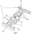
- FIG. 3 illustrates a partial structural schematic diagram of the sleeper beam in FIG. 2 (where an upper cover plate is removed);
- FIG. 4 illustrates a structural schematic diagram of the sleeper beam in FIG. 2 in another direction
- FIG. 5 illustrates a structural schematic diagram of a rib plate of the sleeper beam in FIG. 2 ;
- FIG. 6 illustrates a stress nephogram of a partial chassis component of a railway vehicle according to an embodiment of the present disclosure
- FIG. 7 illustrates a stress nephogram of FIG. 6 in another direction.
- 10 sleeper beam
- 11 center pin
- 12 vertical plate
- 13 rib plate
- 131 bulge
- 132 weight-reducing through hole
- 14 web structure
- 141 web
- 142 wire passage hole
- 15 upper cover plate
- 151 through hole
- 152 first penetration-out hole
- 16 lower cover plate
- 161 second penetration-out hole
- 17 inner boundary beam
- 20 lower boundary beam.
- a length direction of a chassis component is an X direction
- a width direction of the chassis component is a Y direction.
- an embodiment of the present disclosure provides a chassis component of a railway vehicle.
- the chassis component of the present embodiment includes two spaced lower boundary beams 20 and two spaced sleeper beams 10 .
- the two spaced sleeper beams 10 are provided between the two lower boundary beams 20 along a length direction of the lower boundary beams 20 , and at least one of the sleeper beams 10 includes a web structure 14 , a center pin 11 and a mounting frame.
- the center pin 11 is connected with a bogie of a railway vehicle, the mounting frame is connected with the web structure 14 , the center pin 11 is provided on the mounting frame, the mounting frame includes a plurality of vertical plates 12 , and the plurality of vertical plates 12 are provided along an outer wall surface of the center pin 11 at intervals.
- the plurality of vertical plates 12 are provided on the outer wall surface of the center pin 11 to form the mounting frame, so that the connecting area between the center pin 11 and the web structure 14 is increased, thus improving the connecting strength between the center pin 11 and the web structure 14 .
- the mounting frame is additionally provided to connect the center pin 11 and the web structure 14 of the sleeper beam 10 , the plurality of vertical plates 12 are used to increase the connecting strength between the mounting frame and the center pin 11 , and then the mounting frame provided with the center pin 11 is connected to the web structure 14 , so that the connecting strength between the center pin 11 and the web structure 14 is improved, thus improving the overall strength of the sleeper beam 10 .
- one sleeper beam 10 includes a web structure 14 , a center pin 11 and a mounting frame.
- the center pin 11 is connected with a bogie of a railway vehicle
- the mounting frame is connected with the web structure 14
- the center pin 11 is provided on the mounting frame
- the mounting frame includes a plurality of vertical plates 12
- the plurality of vertical plates 12 are provided along an outer wall surface of the center pin 11 at intervals.
- the other sleeper beam 10 can use the above structure, or the structure in the related art.
- a joint between the sleeper beam 10 and the center pin 11 on the chassis component of the railway vehicle is a stress concentration area on the chassis component.
- the center pin 11 in the embodiment of the present disclosure is connected with the web structure 14 of the sleeper beam 10 through the mounting frame, the connecting strength is good, the connection is firm, and the normal operation of the railway vehicle is ensured.
- the plurality of vertical plates 12 are provided on the outer wall surface of the center pin 11 in an X shape, each vertical plate 12 being welded to the outer wall surface of the center pin 11 .
- the mounting frame is composed of four vertical plates 12 , the four vertical plates 12 being provided on the outer wall surface of the center pin 11 in an X shape.
- the arrangement improves the strength of the mounting frame, and the four vertical plates 12 simultaneously support the center pin 11 , thereby improving the connecting strength between the center pin 11 and the mounting frame.
- the center pin 11 is not separated from the mounting frame, and can be better connected with the bogie.
- the four vertical plates 12 are welded to the outer wall surface of the center pin 11 respectively, and compared with bolt connection between the center pin and the sleeper beam in the related art, the connecting mode of the embodiment of the present disclosure is firmer.
- the four vertical plates 12 and the center pin 11 are welded together to form a whole, thereby ensuring the overall strength of the sleeper beam 10 .
- the number of vertical plates 12 of the mounting frame is not limited to 4, and can be appropriately set according to the internal space of the sleeper beam 10 .
- the at least one of the sleeper beams 10 includes two web structures 14 , the mounting frame being located between the two web structures 14 .
- the mounting frame is located between the two web structures 14 , and the mounting frame is connected with the two web structures 14 respectively, so that two ends of the mounting frame are fixed, and the stability of the mounting frame is improved, thus ensuring the stability of connection between the center pin 11 and the web structure 14 of the sleeper beam 10 .
- the each of the sleeper beam 10 further includes a plurality of rib plates 13
- the web structure 14 includes two spaced webs 141
- the plurality of rib plates 13 are provided between the two webs 141 at intervals.
- the plurality of rib plates 13 are provided between the two webs 141 , and in an exemplary embodiment, the plurality of rib plates 13 are provided between the two webs 141 in parallel.
- the arrangement improves the structural strength of the sleeper beam 10 , and the plurality of rib plates 13 can effectively share an action force transferred to the sleeper beam 10 , thereby improving the bearing capacity of the sleeper beam 10 .
- the plurality of rib plates 13 provided between the two webs 141 may form an included angle, and a specific arrangement mode may be selected according to the bearing situation of the sleeper beam 10 .
- each of the web structures 14 is connected with at least one vertical plate 12 of the mounting frame through at least one rib plate 13 .
- each of the web structures 14 is connected with the two vertical plates 12 of the mounting frame through an outermost rib plate 13 , that is, the rib plate 13 closest to the mounting frame is connected with the two vertical plates 12 , and the rib plate 13 is connected with the two webs 141 of the web structure 14 .
- the mounting frame is connected with the web structure 14 through the rib plate 13 .
- the arrangement mode of the present application converts line-to-line connection between the mounting frame and the web structure 14 into line-to-surface connection between the vertical plate 12 and the rib plate 13 and line-to-surface connection between the web 141 and the rib plate 13 , so that the connecting strength between the mounting frame and the web structure 14 is improved, and the stability of connection between the mounting frame and the web structure 14 is ensured, thus ensuring the stability of connection between the center pin 11 and the web structure 14 .
- At least one rib plate 13 included in the plurality of rib plates 13 is provided with a weight-reducing through hole 132 .
- each of the rib plates 13 is provided with a weight-reducing through hole 132 .
- the weight of the rib plate 13 is reduced, thus realizing the light weight of the sleeper beam 10 , and reducing the weight of the chassis component. Further, by providing the weight-reducing through hole 132 , the transfer of the impact force can be stopped when the vehicle body is impacted, thereby avoiding damage to a rear end of the vehicle body caused by the impact force, and improving the safety of the vehicle body.
- the size of the rib plate 13 may be designed as required, and the weight-reducing through hole 132 may also be provided on a part of the rib plates 13 , so as to ensure the strength of the sleeper beam 10 and reduce the weight of the sleeper beam 10 .
- each web 141 is provided with a wire passage hole 142 .
- a wire harness may pass through the chassis component of the railway vehicle, and in order to facilitate the connection and penetration of the wire harness, a wire passage hole 142 is provided on the web 141 for the penetration out or in of the wire harness.
- the wire passage holes 142 on the two webs 141 of the web structure 14 are correspondingly provided to facilitate the penetration of the wire harness.
- a pipeline for wire passage may penetrate into the wire passage hole 142 , so that the wire harness penetrates into the pipeline for the storage of the wire harness, thereby avoiding damage to the wire harness caused by wire harness exposure.
- the at least one of the sleeper beams 10 further includes an upper cover plate 15 covering the webs 141 , the upper cover plate 15 is provided with a plurality of through holes 151 , at least one of the rib plates 13 is provided with a bulge 131 , and the bulge 131 matches the corresponding through hole 151 .
- each rib plate 13 is provided with a bulge 131
- the upper cover plate 15 is provided with multiple through holes 151 in one-to-one correspondence with the multiple bulges 131 .
- the bulges 131 on the rib plates 13 are in inserted fit with the through holes 151 on the upper cover plate 15 , so as to connect the upper cover plate 15 and the rib plates 13 together.
- the upper cover plate 15 covers a cavity defined by the web structure 14 and the rib plates 13 , so as to form a box structure of the sleeper beam 10 .
- the fit part is welded, so as to further ensure the connecting strength between the upper cover plate 15 and the rib plate 13 , thereby ensuring the overall strength of the sleeper beam 10 .
- the upper cover plate 15 is provided with a first penetration-out hole 152 , one end of the center pin 11 penetrating out of the first penetration-out hole 152 .
- the arrangement ensures the fit between the center pin 11 and the upper cover plate 15 , the first penetration-out hole 152 limits the center pin 11 , and it is ensured that the center pin 11 is pivoted to the bogie provided at a lower part of the chassis component.
- the at least one of the sleeper beams 10 further includes a lower cover plate 16 provided at a lower part of the webs 141 , the lower cover plate 16 being fixedly connected with each rib plate 13 .
- the upper cover plate 15 corresponds to the lower cover plate 16 , and the upper cover plate 15 , the lower cover plate 16 and the web structure 14 jointly form a box structure.
- the lower cover plate 16 is fixedly connected with each rib plate 13 , thereby ensuring the stability of connection between the rib plate 13 and the lower cover plate 16 .
- each of the webs 141 is welded to the lower cover plate 16
- the rib plate 13 is welded to the webs 141
- welding fixing is performed.
- the arrangement makes the sleeper beam 10 form a stable whole structure, and ensures the overall strength of the sleeper beam 10 .
- the lower cover plate 16 is provided with a second penetration-out hole 161 , the other end of the center pin 11 penetrating out of the second penetration-out hole 161 .
- the arrangement ensures the connection between the center pin 11 and the bogie provided at the lower part of the chassis component, thus ensuring that the sleeper beam 10 may transfer force and torque transferred from the bogie to the vehicle body.
- the at least one of the sleeper beams 10 further includes two spaced inner boundary beams 17 , the two inner boundary beams 17 being in one-to-one corresponding connection with the two lower boundary beams 20 .
- the two inner boundary beams 17 are spaced at two ends of the sleeper beam 10 . Moreover, the two inner boundary beams 17 are in one-to-one corresponding connection with the two lower boundary beams 20 respectively so as to connect the sleeper beam 10 and the lower boundary beams 20 .
- each of the inner boundary beams 17 is welded to the corresponding lower boundary beam 20 , thereby ensuring the connecting strength between the sleeper beam 10 and the lower boundary beam 20 .
- each of the inner boundary beams 17 is connected with two webs 141 of at least one web structure 14 .
- the sleeper beam 10 includes two web structures 14 , the two web structures 14 being located on two sides of the mounting frame respectively.
- the inner boundary beams 17 located on a same side of the mounting frame are welded to the two webs 141 of the web structure 14 respectively.
- the arrangement forms a complete cavity inside the sleeper beam 10 , and the web 141 is welded to the inner boundary beam 17 , thus ensuring the overall strength of the sleeper beam 10 .
- the embodiment of the present disclosure also provides a railway vehicle.
- the railway vehicle of the present embodiment includes a vehicle body structure and a chassis component connected with the vehicle body structure, the chassis component being the above chassis component.
- the mounting frame is additionally provided to connect the center pin 11 and the web structure 14 of the sleeper beam 10 , a plurality of vertical plates 12 are used to increase the connecting strength between the mounting frame and the center pin 11 , and then the mounting frame provided with the center pin 11 is connected with the web structure 14 , so that the connecting strength between the center pin 11 and the web structure 14 is improved, thus improving the overall strength of the sleeper beam 10 . Therefore, the railway vehicle having the above chassis component also has the above advantages.
- a plurality of vertical plates 12 are provided on the outer wall surface of a center pin 11 to form an X-shaped mounting frame, and the mounting frame connects the center pin 11 and a web structure 14 into a whole.
- the plurality of vertical plates 12 are welded to the center pin 11
- the multiple vertical plates 12 are welded to one of rib plates 13
- the web structure 14 is welded to the one of rib plate 13 , so as to fixedly connect the center pin 11 and the web structure 14 .
- the connection mode of the embodiment of the present disclosure is firmer.
- the rib plate 13 is provided inside a sleeper beam 10 , the lower end of the rib plate 13 is welded to a lower cover plate 16 , the upper end of the rib plate 13 is provided with a bulge 131 and is inserted into a through hole 151 on an upper cover plate 15 , and the insertion part is welded, so that the connecting strength between the rib plate 13 and the upper cover plate 15 is ensured, thus improving the overall strength of the sleeper beam 10 .
- the above embodiment of the present disclosure achieves the following technical effects: the plurality of vertical plates are provided on the outer wall surface of the center pin to form the mounting frame, so that the connecting area between the center pin and the web structure is increased, thus improving the connecting strength between the center pin and the web structure.
- the mounting frame is additionally provided to connect the center pin and the web structure of the sleeper beam
- the plurality of vertical plates are used to increase the connecting strength between the mounting frame and the center pin
- the mounting frame provided with the center pin is connected to the web structure, so that the connecting strength between the center pin and the web structure is improved, thus improving the overall strength of the sleeper beam.
Landscapes
- Engineering & Computer Science (AREA)
- Mechanical Engineering (AREA)
- Connection Of Plates (AREA)
- Bridges Or Land Bridges (AREA)
Abstract
Description
Claims (18)
Applications Claiming Priority (2)
| Application Number | Priority Date | Filing Date | Title |
|---|---|---|---|
| CN201811038273.XA CN109131406B (en) | 2018-09-06 | 2018-09-06 | Railway vehicle's chassis subassembly and railway vehicle |
| CN201811038273.X | 2018-09-06 |
Publications (2)
| Publication Number | Publication Date |
|---|---|
| US20190077424A1 US20190077424A1 (en) | 2019-03-14 |
| US11046336B2 true US11046336B2 (en) | 2021-06-29 |
Family
ID=64827417
Family Applications (1)
| Application Number | Title | Priority Date | Filing Date |
|---|---|---|---|
| US16/185,334 Active 2039-10-23 US11046336B2 (en) | 2018-09-06 | 2018-11-09 | Chassis component of railway vehicle, and railway vehicle |
Country Status (2)
| Country | Link |
|---|---|
| US (1) | US11046336B2 (en) |
| CN (1) | CN109131406B (en) |
Cited By (1)
| Publication number | Priority date | Publication date | Assignee | Title |
|---|---|---|---|---|
| US20200391772A1 (en) * | 2019-06-14 | 2020-12-17 | Trinity Rail Group, Llc | Railcar cover plate |
Families Citing this family (1)
| Publication number | Priority date | Publication date | Assignee | Title |
|---|---|---|---|---|
| DE102020205577A1 (en) * | 2020-05-04 | 2021-11-04 | Siemens Mobility GmbH | Arrangement for the transmission of longitudinal forces in a rail vehicle |
Citations (19)
| Publication number | Priority date | Publication date | Assignee | Title |
|---|---|---|---|---|
| US3770139A (en) | 1972-03-21 | 1973-11-06 | Buckeye Steel Castings Co | Car body center brace and center plate |
| US3831530A (en) | 1972-10-19 | 1974-08-27 | Dresser Ind | Railway car center bearing assembly |
| US3859928A (en) | 1973-09-21 | 1975-01-14 | Pullman Transport Leasing Co | Railway car articulated center plate |
| US4589348A (en) * | 1983-10-24 | 1986-05-20 | Portland General Electric Company | Retrofitted railway car and method of producing same |
| US5809899A (en) * | 1996-06-28 | 1998-09-22 | Amsted Industries Incorporated | Draft sill and wheel truck connection |
| US6324995B1 (en) * | 1999-06-04 | 2001-12-04 | Amstead Industries Incorporated | Railway car center filler plate |
| CN101445117A (en) | 2008-12-25 | 2009-06-03 | 南车眉山车辆有限公司 | Center plate for lorry |
| CN101970275A (en) | 2008-03-14 | 2011-02-09 | 西门子公司 | Pivot pin for longitudinal and transverse force transmission between a truck and a carriage body and method for the production of a pivot pin |
| CN102673591A (en) * | 2012-05-11 | 2012-09-19 | 长春轨道客车股份有限公司 | Connection sleeper beam for intercity motor train unit |
| CN104029692A (en) | 2014-06-25 | 2014-09-10 | 齐齐哈尔轨道交通装备有限责任公司 | Railway container vehicle and chassis for same |
| CN104203708A (en) | 2012-04-02 | 2014-12-10 | 川崎重工业株式会社 | Railroad vehicle |
| CN206288021U (en) * | 2016-11-07 | 2017-06-30 | 中车长春轨道客车股份有限公司 | The new sleeper beam structure of city railway vehicle |
| CN106964902A (en) | 2017-04-11 | 2017-07-21 | 中车青岛四方机车车辆股份有限公司 | A kind of complex welding method of sleeper beam, sleeper beam and the rail vehicle with the sleeper beam |
| CN107107921A (en) | 2014-11-21 | 2017-08-29 | L·托尼 | The lateral member for the railcar that the compartment main body of railcar is linked with its bogie |
| CN107618527A (en) | 2017-08-09 | 2018-01-23 | 中车青岛四方机车车辆股份有限公司 | Sleeper beam and there is its vehicle |
| CN107628050A (en) * | 2017-08-29 | 2018-01-26 | 中车大连机车车辆有限公司 | Bolster formula bogie articulated car sleeper beam structure |
| CN107914726A (en) * | 2017-11-16 | 2018-04-17 | 江苏恒神股份有限公司 | A kind of Subway Body carbon fibre composite sleeper beam |
| US20190084591A1 (en) * | 2018-09-06 | 2019-03-21 | Crrc Qingdao Sifang Co., Ltd. | Chassis Component of Railway Vehicle, and Railway Vehicle |
| US10730145B2 (en) * | 2017-04-11 | 2020-08-04 | Crrc Qingdao Sifang Co., Ltd. | Beam structure and hybrid welding method thereof |
-
2018
- 2018-09-06 CN CN201811038273.XA patent/CN109131406B/en active Active
- 2018-11-09 US US16/185,334 patent/US11046336B2/en active Active
Patent Citations (19)
| Publication number | Priority date | Publication date | Assignee | Title |
|---|---|---|---|---|
| US3770139A (en) | 1972-03-21 | 1973-11-06 | Buckeye Steel Castings Co | Car body center brace and center plate |
| US3831530A (en) | 1972-10-19 | 1974-08-27 | Dresser Ind | Railway car center bearing assembly |
| US3859928A (en) | 1973-09-21 | 1975-01-14 | Pullman Transport Leasing Co | Railway car articulated center plate |
| US4589348A (en) * | 1983-10-24 | 1986-05-20 | Portland General Electric Company | Retrofitted railway car and method of producing same |
| US5809899A (en) * | 1996-06-28 | 1998-09-22 | Amsted Industries Incorporated | Draft sill and wheel truck connection |
| US6324995B1 (en) * | 1999-06-04 | 2001-12-04 | Amstead Industries Incorporated | Railway car center filler plate |
| CN101970275A (en) | 2008-03-14 | 2011-02-09 | 西门子公司 | Pivot pin for longitudinal and transverse force transmission between a truck and a carriage body and method for the production of a pivot pin |
| CN101445117A (en) | 2008-12-25 | 2009-06-03 | 南车眉山车辆有限公司 | Center plate for lorry |
| CN104203708A (en) | 2012-04-02 | 2014-12-10 | 川崎重工业株式会社 | Railroad vehicle |
| CN102673591A (en) * | 2012-05-11 | 2012-09-19 | 长春轨道客车股份有限公司 | Connection sleeper beam for intercity motor train unit |
| CN104029692A (en) | 2014-06-25 | 2014-09-10 | 齐齐哈尔轨道交通装备有限责任公司 | Railway container vehicle and chassis for same |
| CN107107921A (en) | 2014-11-21 | 2017-08-29 | L·托尼 | The lateral member for the railcar that the compartment main body of railcar is linked with its bogie |
| CN206288021U (en) * | 2016-11-07 | 2017-06-30 | 中车长春轨道客车股份有限公司 | The new sleeper beam structure of city railway vehicle |
| CN106964902A (en) | 2017-04-11 | 2017-07-21 | 中车青岛四方机车车辆股份有限公司 | A kind of complex welding method of sleeper beam, sleeper beam and the rail vehicle with the sleeper beam |
| US10730145B2 (en) * | 2017-04-11 | 2020-08-04 | Crrc Qingdao Sifang Co., Ltd. | Beam structure and hybrid welding method thereof |
| CN107618527A (en) | 2017-08-09 | 2018-01-23 | 中车青岛四方机车车辆股份有限公司 | Sleeper beam and there is its vehicle |
| CN107628050A (en) * | 2017-08-29 | 2018-01-26 | 中车大连机车车辆有限公司 | Bolster formula bogie articulated car sleeper beam structure |
| CN107914726A (en) * | 2017-11-16 | 2018-04-17 | 江苏恒神股份有限公司 | A kind of Subway Body carbon fibre composite sleeper beam |
| US20190084591A1 (en) * | 2018-09-06 | 2019-03-21 | Crrc Qingdao Sifang Co., Ltd. | Chassis Component of Railway Vehicle, and Railway Vehicle |
Cited By (1)
| Publication number | Priority date | Publication date | Assignee | Title |
|---|---|---|---|---|
| US20200391772A1 (en) * | 2019-06-14 | 2020-12-17 | Trinity Rail Group, Llc | Railcar cover plate |
Also Published As
| Publication number | Publication date |
|---|---|
| CN109131406B (en) | 2020-11-10 |
| US20190077424A1 (en) | 2019-03-14 |
| CN109131406A (en) | 2019-01-04 |
Similar Documents
| Publication | Publication Date | Title |
|---|---|---|
| CN106364511B (en) | Rail vehicle end rests the head on external structure | |
| US11046336B2 (en) | Chassis component of railway vehicle, and railway vehicle | |
| US11225270B2 (en) | Chassis component of railway vehicle, and railway vehicle | |
| WO2020010853A1 (en) | Underframe structure and train having same | |
| JP5227234B2 (en) | Body structure for railway vehicles | |
| CN104648422A (en) | Railway vehicle and local multifunctional component thereof | |
| US20190144011A1 (en) | Chassis Component of Railway Vehicle, and Railway Vehicle | |
| WO2020134001A1 (en) | Double-layer rail vehicle and underframe thereof | |
| AU2016364101A1 (en) | Carrying connection device for road-rail combined transport vehicle | |
| WO2020192032A1 (en) | End chassis structure for use in railway vehicle and railway vehicle | |
| WO2021114346A1 (en) | Rail vehicle, and vehicle body and end underframe thereof | |
| WO2020133934A1 (en) | Railway car, car body thereof, and end underframe | |
| CN204161464U (en) | Automobile-used sectional beam, vehicle frame and vehicle | |
| CN102774425A (en) | Vehicle frame | |
| CN202829270U (en) | Lifting tool for integral floor of locomotive cab | |
| CN109109890A (en) | The underframe assemblies and rail vehicle of rail vehicle | |
| CN211893401U (en) | Auxiliary frame of fire engine and fire engine | |
| CN106080471A (en) | A kind of automobile buffer beam and energy-absorption box thereof | |
| CN209159386U (en) | A kind of fixed device of overhead type power battery cabinet | |
| CN207892340U (en) | The bracing wire construction hole fixture of steel tower is combined for four angle steel | |
| CN110667628A (en) | Car body chassis and have its tram | |
| CN205327070U (en) | Bogie of anticreep device and applied this anticreep device | |
| CN210680703U (en) | Rail vehicle and floor structure thereof | |
| CN108909747A (en) | Crossbeam and train with it | |
| US20230347981A1 (en) | Structural node for a motor vehicle front lower load path, and process for assembling said structural node. |
Legal Events
| Date | Code | Title | Description |
|---|---|---|---|
| AS | Assignment |
Owner name: CRRC QINGDAO SIFANG CO., LTD., CHINA Free format text: ASSIGNMENT OF ASSIGNORS INTEREST;ASSIGNORS:WANG, XIAOJIE;WANG, YU;TIAN, HONGLEI;AND OTHERS;REEL/FRAME:047460/0738 Effective date: 20181105 |
|
| FEPP | Fee payment procedure |
Free format text: ENTITY STATUS SET TO UNDISCOUNTED (ORIGINAL EVENT CODE: BIG.); ENTITY STATUS OF PATENT OWNER: LARGE ENTITY |
|
| STPP | Information on status: patent application and granting procedure in general |
Free format text: APPLICATION DISPATCHED FROM PREEXAM, NOT YET DOCKETED |
|
| STPP | Information on status: patent application and granting procedure in general |
Free format text: DOCKETED NEW CASE - READY FOR EXAMINATION |
|
| STPP | Information on status: patent application and granting procedure in general |
Free format text: NON FINAL ACTION MAILED |
|
| STPP | Information on status: patent application and granting procedure in general |
Free format text: RESPONSE TO NON-FINAL OFFICE ACTION ENTERED AND FORWARDED TO EXAMINER |
|
| STPP | Information on status: patent application and granting procedure in general |
Free format text: NOTICE OF ALLOWANCE MAILED -- APPLICATION RECEIVED IN OFFICE OF PUBLICATIONS |
|
| STPP | Information on status: patent application and granting procedure in general |
Free format text: PUBLICATIONS -- ISSUE FEE PAYMENT RECEIVED |
|
| STPP | Information on status: patent application and granting procedure in general |
Free format text: PUBLICATIONS -- ISSUE FEE PAYMENT VERIFIED |
|
| STCF | Information on status: patent grant |
Free format text: PATENTED CASE |