US11043061B2 - Dispenser of shelved products - Google Patents
Dispenser of shelved products Download PDFInfo
- Publication number
- US11043061B2 US11043061B2 US16/530,928 US201916530928A US11043061B2 US 11043061 B2 US11043061 B2 US 11043061B2 US 201916530928 A US201916530928 A US 201916530928A US 11043061 B2 US11043061 B2 US 11043061B2
- Authority
- US
- United States
- Prior art keywords
- divider
- belt
- dispenser
- carriage
- product
- Prior art date
- Legal status (The legal status is an assumption and is not a legal conclusion. Google has not performed a legal analysis and makes no representation as to the accuracy of the status listed.)
- Active
Links
Images


Classifications
-
- G—PHYSICS
- G07—CHECKING-DEVICES
- G07F—COIN-FREED OR LIKE APPARATUS
- G07F11/00—Coin-freed apparatus for dispensing, or the like, discrete articles
- G07F11/02—Coin-freed apparatus for dispensing, or the like, discrete articles from non-movable magazines
- G07F11/04—Coin-freed apparatus for dispensing, or the like, discrete articles from non-movable magazines in which magazines the articles are stored one vertically above the other
- G07F11/16—Delivery means
- G07F11/165—Delivery means using xyz-picker or multi-dimensional article picking arrangements
-
- G—PHYSICS
- G07—CHECKING-DEVICES
- G07F—COIN-FREED OR LIKE APPARATUS
- G07F11/00—Coin-freed apparatus for dispensing, or the like, discrete articles
- G07F11/02—Coin-freed apparatus for dispensing, or the like, discrete articles from non-movable magazines
- G07F11/38—Coin-freed apparatus for dispensing, or the like, discrete articles from non-movable magazines in which the magazines are horizontal
- G07F11/42—Coin-freed apparatus for dispensing, or the like, discrete articles from non-movable magazines in which the magazines are horizontal the articles being delivered by motor-driven means
Definitions
- the present subject matter relates to the field of vending machines and more particularly to methods and apparatus for moving products within vending machines.
- vending machine designs can typically be grouped into two distinct categories; those that display the products to be dispensed, and those that do not.
- Primary considerations in development of vending machines include the reliability of the mechanism to dispense a selected product each time it is selected by a consumer as well as the efficiency of the machine in terms of the variety and capacity of SKUs offered for the cost and size of the machine. Data suggests that vending machines that display products for sale generate higher sales than those with closed fronts that hide the actual product being offered for sale and instead substitute branding and advertising panels.
- many vending machine designs such as those for popular beverage brands from Coke and Pepsi had closed fronts and opted for a branding panel instead of a glass front to display a showcase of the products for sale.
- shelf dispenser that increases the capacity of the shelf by reducing the overall width, and therefore the overall forward-facing dispenser surface area, of the dispenser. Furthermore, it is desirable to have a shelf dispenser that may interact with sensors to allow the vending machine to determine the location of the dispenser, the number of products in each dispenser area, and, from that information, the inventory of the vending machine.
- FIG. 1 is a perspective view depicting an embodiment of dispensers of shelved products incorporated into a vending machine
- FIG. 2 is a perspective view depicting an embodiment of dispensers of shelved products on a shelf of a vending machine
- FIG. 3 is a perspective view depicting an embodiment of a dispenser of shelved products
- FIG. 4 is a side view depicting a partially disassembled embodiment of a dispenser of shelved products
- FIG. 5 is a partial front view depicting an embodiment of dispensers of shelved products attached to a vending machine
- FIG. 6 is a partial perspective view depicting an embodiment of dispensers of shelved products attached to a vending machine
- FIG. 7A is a top view of an embodiment of a dispenser of shelved products
- FIG. 7B is a side view of an embodiment of a dispenser of shelved products
- FIG. 7C is a front view of an embodiment of a dispenser of shelved products
- FIG. 8 is an expanded perspective view of an embodiment of a dispenser of shelved products
- FIG. 9A is a partially disassembled perspective view of a divider front end of a dispenser of shelved products
- FIG. 9B is a perspective view of a divider front end of a dispenser of shelved products
- FIG. 10A is a transparent perspective view of a belt tensioner of a dispenser of shelved products
- FIG. 10B is an expanded perspective view of a belt tensioner of a dispenser of shelved products
- FIG. 11A is a perspective view of a timing belt clamp a dispenser of shelved products
- the pusher carriage is compact and allows the dispenser to support different lengths of pusher extension fins, which may be made of a lighter or cheaper material, and easy to manufacture.
- FIG. 3 is a perspective view depicting an embodiment of a dispenser of shelved products.
- dispenser 100 includes a divider 310 and an extender bracket 330 .
- Divider 310 includes a front end 320 , a timing belt 370 , a pusher carriage ( FIG. 4 , element 410 , obscured by extender bracket 330 ), and a belt tensioner 390 .
- the obscured pusher carriage 410 connects extender bracket 330 to divider 310 using bracket hooks 335 .
- the pusher carriage runs between front end 320 and belt tensioner 390 .
- Front end 320 further includes flat spring retainers 340 , a drive gear 350 , and latch pins 360 .
- FIG. 6 is a partial perspective view depicting an embodiment of dispensers 100 of shelved products attached to a vending machine and oval holes 210 for receiving latch pins 360 .
- FIG. 7B is a side view of an embodiment of a dispenser of shelved products.
- pusher carriage 410 is shown to be retained by and slide within divider track 380 .
- FIG. 9B is a perspective view of divider front end 320 of a dispenser of shelved products.
- FIG. 9B shows flat spring retainers 340 in more detail.
- sensor 1910 may be a laser range-finding sensor positioned above drive gear 1510 .
- Sensor 1910 directs the laser down dispenser 1600 and receives a signal that measures the distance from the laser to tab 1610 .
- Tab 1610 positioned above divider 310 of dispenser 1600 and connected to carriage 1630 , sits at or near the back of the product, and so provides the distance from chassis 1900 to the furthest back product.
- controller 120 may determine the number of products on the shelf, e.g., if a 92 mm depth is detected and each product is 18 mm deep, there are 5 products on the shelf.
- the database referenced to perform an inventory may include the superset of products that can be sold in the machine along with the dimensions of each product.
- the database may further include a planogram for the vending machine of interest where the planogram stores the descriptions (e.g., dimensions) of the specific products in the vending machine along with each product's orientation with respect to the shelf (or dispenser).
- the vending machine may be programmed to automatically count inventory in the machine when desired or scheduled by positioning the conveyor bucket at each shelf, and dispenser on that shelf, and reading the distance from the tag to the conveyor bucket using the range sensor. With the distance known, vending machine software then subtracts the distance from the sensor position to the front of the shelf (a known quantity) and then divides the remaining distance by the depth of the product associated with that dispenser position. The result yields the number of products at that shelf/dispenser position.
- the conveyor bucket may also engage the pusher to ensure that all items at that shelf/dispenser position are moved to the front of the shelf before measuring. This embodiment may include equipping the conveyor bucket with a sensor to determine when product is at the front of the shelf. Once a particular shelf/dispenser position has been measured, the conveyor bucket is repositioned to a new shelf/dispenser position and the process repeated until all shelf/dispenser positions have been evaluated.
- FIG. 18 is a side view depicting dispenser 1600 of shelved products.
- tab 1610 is shown to be the same distance as extender face 332 from front end 320 .
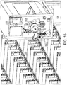
- FIG. 19 is a partially transparent perspective view depicting a mechanism for driving an embodiment of a dispenser of shelved products.
- the description of FIG. 19 incorporates the description of FIG. 15 , with FIG. 19 further showing modifications to the conveyor bucket 1600 of FIG. 15 .
- a conveyor bucket 1900 includes a first range sensor 1910 and a second range sensor 1920 .
- Range sensor 1910 as described with respect to FIG. 16 , is used to measure the distance from conveyor bucket 1900 to a tab 1610 (not shown in FIG. 19 ) on extender bracket 1630 of dispenser 1600 . The measured distance is illustrated by the arrow extending from sensor 1910 .
- the distance measured by sensor 1910 is then used to calculate a number of remaining products within the row defined by dispenser 1600 .
- range sensor 1920 is used to detect the location of a dispenser along a row by detecting the presence of latch pins 360 through slots in the shelf.
- latch pins 360 extend through and below the shelf.
- the slot in each shelf below a dispenser is darkened, which indicates that the latch pins for that dispenser are located behind that slot.
- latch pins 360 are made of plastic and, during manufacture, an IR-reflecting ink may be injected into the plastic resulting in the latch pins 360 glowing (or otherwise reflecting IR light more efficiently) when hit with IR light. Such glowing latch pins are more easily detected by IR range sensors.
- the positions of the shelves and the dispensers within a vending machine may be automatically detected by conveyor bucket 1900 .
- shelves are placed along the Y axis and dispensers are placed along the X axis of each shelf.
- Conveyor bucket 1900 may then be moved vertically by vending machine 105 with sensor 1910 or sensor 1920 or both registering the location of each shelf by detecting the reduction in the distance sensed. The location of each shelf is then stored with respect to the vertical movement of conveyor bucket 1900 . Subsequently, conveyor bucket 1900 may be positioned to align sensor 1920 with the slots of a particular shelf.
- a magnet may be affixed to the front of dispenser 1600 , e.g., below drive gear 350 , with a corresponding magnetic sensor added to 1900 , e.g., near the position of sensor 1920 . Information from the magnetic sensor may then allow controller 120 to determine the location of dispenser 1600 , both horizontally and vertically.
- FIG. 20 is a simplified, exemplary block diagram of an embodiment of a system 2000 for implementing the embodiments of systems and methods disclosed herein.
- System 2000 may include a number of sensors, e.g., a tab range sensor 2005 (e.g., sensor 1910 as described within this disclosure), a dispenser position sensor 2010 (e.g., range sensor 1920 , as described within this disclosure), a magnetic dispenser position sensor 2020 , a bucket X-position sensor 2025 , and a bucket Y-position sensor 2035 , for developing data regarding the position of a tab, a position of a dispenser, or a position of a conveyor bucket.
- sensors e.g., a tab range sensor 2005 (e.g., sensor 1910 as described within this disclosure), a dispenser position sensor 2010 (e.g., range sensor 1920 , as described within this disclosure), a magnetic dispenser position sensor 2020 , a bucket X-position sensor 2025 , and a bucket Y-position sensor 2035 , for developing data regarding the position of a tab
- Sensors 2005 , 2010 , 2020 , 2025 , and 2035 are in communication with a computing device 2015 , e.g., controller 120 .
- Computing device 2015 may further be in control of bucket 1500 , 1900 , and dispensing door 110 .
- Computing device 2015 may receive input from interface 115 and display information on interface 115 .
- Sensors 2005 , 2010 , 2020 , 2025 , and 2035 may supply data to computing device 2015 via communication links 2030 .
- Computing device 2015 may include a user interface (e.g., interface 115 ) and software, which may implement the steps of the methods disclosed within.
- Computing device 2015 may receive data from sensors 2005 , 2010 , 2020 , 2025 , and 2035 , via communication links 2030 , which may be hardwire links, optical links, satellite or other wireless communications links, wave propagation links, or any other mechanisms for communication of information.
- communication links 2030 may be hardwire links, optical links, satellite or other wireless communications links, wave propagation links, or any other mechanisms for communication of information.
- Various communication protocols may be used to facilitate communication between the various components shown in FIG. 20 .
- Distributed system 2000 in FIG. 20 is merely illustrative of an embodiment and does not limit the scope of the systems and methods as recited in the claims.
- the elements of system 2000 are incorporated into a vending machine (e.g., vending machine 100 ).
- Computing device 2015 may be responsible for receiving data from sensors 2005 , 2010 , 2020 , 2025 , and 2035 , performing processing required to implement the steps of the methods, and for interfacing with the user.
- computing device 2015 may receive processed data from sensors 2005 , 2010 , 2020 , 2025 , and 2035 .
- the processing required is performed by computing device 2015 .
- computing device 2015 runs an application for receiving user data, performing the steps of the method, and interacting with the user.
- computing device 2015 may be in communication with a server, which performs the required processing, with computing device 2015 being an intermediary in communications between the user and the processing server.
- System 2000 may enable users to access and query information developed by the disclosed methods.
- Some example computing devices 2015 include devices running the Apple iOS®, Android® OS, Google Chrome® OS, Symbian OS®, Windows Mobile® OS, Windows Phone, BlackBerry® OS, Embedded Linux, Tizen, Sailfish, webOS, Palm OS® or Palm Web OS®.
- FIG. 21 is an exemplary block diagram of a computing device 2015 from the system of FIG. 20 .
- a user interfaces with the system through computing device 2015 , which also receives data and performs the computational steps of the embodiments.
- Computing device 2015 may include a display, screen, or monitor 2105 , housing 2110 , input device 2115 , sensors 2150 , and a security application 2145 .
- Housing 2110 houses familiar computer components, some of which are not shown, such as a processor 2120 , memory 2125 , battery 2130 , speaker, transceiver, antenna 2135 , microphone, ports, jacks, connectors, camera, input/output (I/O) controller, display adapter, network interface, mass storage devices 2140 , and the like.
- sensors 2150 may include sensors 2005 , 2010 , 2020 , 2025 , and 2035 in communication with computing device 2015
- Input device 2115 may also include a touchscreen (e.g., resistive, surface acoustic wave, capacitive sensing, infrared, optical imaging, dispersive signal, or acoustic pulse recognition), keyboard (e.g., electronic keyboard or physical keyboard), buttons, switches, stylus, or combinations of these.
- a touchscreen e.g., resistive, surface acoustic wave, capacitive sensing, infrared, optical imaging, dispersive signal, or acoustic pulse recognition
- keyboard e.g., electronic keyboard or physical keyboard
- Display 2105 may include dedicated LEDs for providing directing signals and feedback to a user.
- Mass storage devices 2140 may include flash and other nonvolatile solid-state storage or solid-state drive (SSD), such as a flash drive, flash memory, or USB flash drive.
- SSD solid-state drive
- Other examples of mass storage include mass disk drives, floppy disks, magnetic disks, optical disks, magneto-optical disks, fixed disks, hard disks, CD-ROMs, recordable CDs, DVDs, recordable DVDs (e.g., DVD-R, DVD+R, DVD-RW, DVD+RW, HD-DVD, or Blu-ray Disc), battery-backed-up volatile memory, tape storage, reader, and other similar media, and combinations of these.
- SSD solid-state drive
- Other examples of mass storage include mass disk drives, floppy disks, magnetic disks, optical disks, magneto-optical disks, fixed disks, hard disks, CD-ROMs, recordable CDs, DVDs, recordable DVDs (e.g., DVD-R, DVD+R, DVD-RW, DVD+
- An apparatus for a vending machine comprising: an elongate divider; a first drive gear included at a first end of the elongate divider; a linear positioner in connection with the first drive gear; a carriage connected to the linear positioner; and an extender connected to the carriage, wherein: rotation of the first drive gear causes the linear positioner to move the carriage along the elongate divider between a first end of the elongate divider and a second end of the elongate divider.
- the linear positioner includes: a) a belt running along the elongate divider between a drive pulley and an idler pulley and driven by the first drive gear; or b) a threaded shaft running along the elongate divider and driven by the first drive gear and a bevel gear.
- the linear positioner includes a belt running along the elongate divider between a drive pulley and an idler pulley and driven by the first drive gear;
- the drive pulley includes a coaxial second drive gear that engages the first drive gear;
- the carriage includes a belt clamp, the belt clamp including a groove dimensioned to receive the belt and a flexible retainer that flexes from an initial position to admit the belt into the groove and returns to the initial position to retain the belt within the groove.
- the belt groove is non-linear, increasing friction between the belt and belt groove, and preventing movement of the carriage with respect to the belt; and the belt clamp further includes teeth at an edge of the belt groove, the teeth configured to partially retain the belt within the groove.
- the divider includes: a front end cap and a rear end cap, the front end cap connected to the first end of the elongate divider and housing the first drive gear, the front end also including a first tab dimensioned to engage a corresponding slot in a shelf of the vending machine; and the rear end cap connected to the second end of the elongate divider and including a second tab dimensioned to engage a corresponding slot in the shelf.
- the divider includes a non-product side; and the carriage includes a tab extending into a space adjacent the non-product side, the tab configured to interact with a position sensor of a moveable platform of the vending machine.
- a kit for an apparatus for a vending machine comprising: an elongate divider; a first drive gear included at a first end of the elongate divider; a linear positioner in connection with the first drive gear; a carriage connected to the linear positioner; and an extender connected to the carriage, wherein, when assembled: rotation of the first drive gear causes the linear positioner to move the carriage along the elongate divider between a first end of the elongate divider and a second end of the elongate divider.
- the linear positioner when assembled: the linear positioner includes a belt running along the elongate divider between a drive pulley and an idler pulley and driven by the first drive gear; the drive pulley includes a coaxial second drive gear that engages the first drive gear; and the carriage includes a belt clamp, the belt clamp including a groove dimensioned to receive the belt and a flexible retainer that flexes from an initial position to admit the belt into the groove and returns to the initial position to retain the belt within the groove.
- the linear positioner includes a belt running along the elongate divider between a drive pulley and an idler pulley and driven by the first drive gear; and the idler pulley is housed by the rear end cap with a spring urging the idler pulley away from the front end cap.
- the divider includes a product side; and the movement of the carriage causes the extender to sweep through a space adjacent to the product side, engage the product, and force the product into the moveable platform.
Landscapes
- Physics & Mathematics (AREA)
- General Physics & Mathematics (AREA)
- Vending Machines For Individual Products (AREA)
- Control Of Vending Devices And Auxiliary Devices For Vending Devices (AREA)
Abstract
Description
Claims (20)
Priority Applications (1)
| Application Number | Priority Date | Filing Date | Title |
|---|---|---|---|
| US16/530,928 US11043061B2 (en) | 2018-08-02 | 2019-08-02 | Dispenser of shelved products |
Applications Claiming Priority (3)
| Application Number | Priority Date | Filing Date | Title |
|---|---|---|---|
| US201862713976P | 2018-08-02 | 2018-08-02 | |
| US201862721450P | 2018-08-22 | 2018-08-22 | |
| US16/530,928 US11043061B2 (en) | 2018-08-02 | 2019-08-02 | Dispenser of shelved products |
Publications (2)
| Publication Number | Publication Date |
|---|---|
| US20200043273A1 US20200043273A1 (en) | 2020-02-06 |
| US11043061B2 true US11043061B2 (en) | 2021-06-22 |
Family
ID=69229785
Family Applications (1)
| Application Number | Title | Priority Date | Filing Date |
|---|---|---|---|
| US16/530,928 Active US11043061B2 (en) | 2018-08-02 | 2019-08-02 | Dispenser of shelved products |
Country Status (4)
| Country | Link |
|---|---|
| US (1) | US11043061B2 (en) |
| CN (1) | CN112639896B (en) |
| GB (1) | GB2591185A (en) |
| WO (1) | WO2020028878A1 (en) |
Cited By (2)
| Publication number | Priority date | Publication date | Assignee | Title |
|---|---|---|---|---|
| US20220058908A1 (en) * | 2020-08-19 | 2022-02-24 | Pepsico, Inc. | Product delivery mechanism for a vending machine |
| US11508201B2 (en) * | 2017-12-29 | 2022-11-22 | Shandong New Beiyang Information Technology Co., Ltd. | Bucket and vending machine |
Families Citing this family (6)
| Publication number | Priority date | Publication date | Assignee | Title |
|---|---|---|---|---|
| CN109993903B (en) * | 2017-12-29 | 2024-01-30 | 山东新北洋信息技术股份有限公司 | Driving device, goods bucket and vending machine |
| CN110390768B (en) * | 2018-04-19 | 2021-08-31 | 山东新北洋信息技术股份有限公司 | Goods quantity detection method and vending machine |
| CN110766860A (en) * | 2018-07-27 | 2020-02-07 | 威海新北洋数码科技有限公司 | Automatic vending machine |
| US11449826B2 (en) * | 2019-03-15 | 2022-09-20 | Hashim Muhammad SIDDIQUI | Systems and methods for autonomous inventory counting and tracking |
| CN113269296A (en) * | 2020-02-14 | 2021-08-17 | 艾利丹尼森零售信息服务公司 | Counting machine and method for counting articles |
| USD983881S1 (en) * | 2020-07-02 | 2023-04-18 | Dongguan Dongwei Electrical and Mechanical Technology Co., Ltd. | Vending machine |
Citations (6)
| Publication number | Priority date | Publication date | Assignee | Title |
|---|---|---|---|---|
| JP2000105864A (en) | 1998-09-28 | 2000-04-11 | Sanyo Electric Co Ltd | Article take-out device of automatic vending machine |
| US20070021866A1 (en) * | 2005-07-21 | 2007-01-25 | Coppola Richard G | Dispenser tray for a vending machine |
| US20120123587A1 (en) * | 2009-08-27 | 2012-05-17 | Utique, Inc. | Inventory storage and dispensing mechanism |
| US20120277904A1 (en) * | 2011-01-04 | 2012-11-01 | Fawn Engineering Corporation | Vending machine with elevator delivery of vended product to customer access |
| US20150189364A1 (en) | 2013-12-26 | 2015-07-02 | Sony Corporation | Signal switching apparatus and method for controlling operation thereof |
| CN206411788U (en) | 2017-01-21 | 2017-08-15 | 淄博市技师学院 | A kind of ejecting device of automatic vending machine |
Family Cites Families (19)
| Publication number | Priority date | Publication date | Assignee | Title |
|---|---|---|---|---|
| US6755322B1 (en) * | 2000-02-22 | 2004-06-29 | Hettie J. Herzog | Automated shopping system and apparatus |
| JP2003132416A (en) * | 2001-10-22 | 2003-05-09 | Sanden Corp | Automatic vending machine |
| US7686185B2 (en) * | 2005-06-02 | 2010-03-30 | Coin Acceptors, Inc. | Dispenser tray for a vending machine |
| US7837058B2 (en) * | 2005-10-14 | 2010-11-23 | Crane Merchandising Systems, Inc. | Product transport system for a vending machine |
| EP1916633B1 (en) * | 2006-10-25 | 2015-12-30 | Sielaff Gmbh & Co. Kg Automatenbau | Dispensing compartment, vending machine and method |
| US8392019B2 (en) * | 2009-08-27 | 2013-03-05 | Utique, Inc. | Modular vending with centralized robotic gantry |
| US9245404B1 (en) * | 2013-01-17 | 2016-01-26 | Michael Martuch | Vending system with recyclable packaging having automated deposit and return |
| CN104392547B (en) * | 2014-10-23 | 2018-05-22 | 上海汉京知识产权服务有限公司 | The mechanism that replenishes and Vending Machine |
| GB201504218D0 (en) * | 2015-03-12 | 2015-04-29 | Heartbeat Mfg Co Redditch The Ltd | Shelf management device |
| CN104821043B (en) * | 2015-05-08 | 2017-09-15 | 广州舟翼智能科技有限公司 | A kind of automatic vending machine |
| CN104778785B (en) * | 2015-05-08 | 2017-05-10 | 广州舟翼智能科技有限公司 | Vending machine |
| CN204731877U (en) * | 2015-05-08 | 2015-10-28 | 广州舟翼智能科技有限公司 | A kind of automatic vending machine |
| AU2016263105A1 (en) * | 2015-05-15 | 2017-12-14 | Rtc Industries, Inc. | Systems and methods for merchandizing electronic displays |
| CN206961236U (en) * | 2017-07-18 | 2018-02-02 | 上海申跃数码科技有限公司 | A kind of novel crawler-type cargo path structure |
| CN107123196A (en) * | 2017-07-18 | 2017-09-01 | 上海申跃数码科技有限公司 | A kind of novel crawler-type cargo path structure |
| CN207182505U (en) * | 2017-08-16 | 2018-04-03 | 北京康得新创科技股份有限公司 | Shipment device and automatic vending machine |
| CN207123895U (en) * | 2017-08-31 | 2018-03-20 | 山东新北洋信息技术股份有限公司 | A kind of automatic vending machine |
| CN108010199A (en) * | 2017-12-25 | 2018-05-08 | 湖南金码智能设备制造有限公司 | The overall welding automatic vending machine pallet being made of independent woven belt cargo path |
| CN108305384A (en) * | 2018-03-29 | 2018-07-20 | 广州舟翼智能科技有限公司 | A kind of motor push rod |
-
2019
- 2019-08-02 US US16/530,928 patent/US11043061B2/en active Active
- 2019-08-02 WO PCT/US2019/045007 patent/WO2020028878A1/en not_active Ceased
- 2019-08-02 GB GB2101738.9A patent/GB2591185A/en not_active Withdrawn
- 2019-08-02 CN CN201980057078.8A patent/CN112639896B/en not_active Expired - Fee Related
Patent Citations (7)
| Publication number | Priority date | Publication date | Assignee | Title |
|---|---|---|---|---|
| JP2000105864A (en) | 1998-09-28 | 2000-04-11 | Sanyo Electric Co Ltd | Article take-out device of automatic vending machine |
| US20070021866A1 (en) * | 2005-07-21 | 2007-01-25 | Coppola Richard G | Dispenser tray for a vending machine |
| US20120123587A1 (en) * | 2009-08-27 | 2012-05-17 | Utique, Inc. | Inventory storage and dispensing mechanism |
| US9443372B2 (en) | 2009-08-27 | 2016-09-13 | Utique, Inc. | Inventory storage and dispensing mechanism |
| US20120277904A1 (en) * | 2011-01-04 | 2012-11-01 | Fawn Engineering Corporation | Vending machine with elevator delivery of vended product to customer access |
| US20150189364A1 (en) | 2013-12-26 | 2015-07-02 | Sony Corporation | Signal switching apparatus and method for controlling operation thereof |
| CN206411788U (en) | 2017-01-21 | 2017-08-15 | 淄博市技师学院 | A kind of ejecting device of automatic vending machine |
Non-Patent Citations (2)
| Title |
|---|
| Notification and Transmittal of International Search Report and Written Opinion, PCT/US2019/045007, dated Oct. 24, 2019, 8 pages. |
| PCT International Preliminary Report on Patentability in Application PCT/US2019/045007, dated Feb. 11, 2021, 8 pages. |
Cited By (2)
| Publication number | Priority date | Publication date | Assignee | Title |
|---|---|---|---|---|
| US11508201B2 (en) * | 2017-12-29 | 2022-11-22 | Shandong New Beiyang Information Technology Co., Ltd. | Bucket and vending machine |
| US20220058908A1 (en) * | 2020-08-19 | 2022-02-24 | Pepsico, Inc. | Product delivery mechanism for a vending machine |
Also Published As
| Publication number | Publication date |
|---|---|
| CN112639896A (en) | 2021-04-09 |
| GB2591185A (en) | 2021-07-21 |
| US20200043273A1 (en) | 2020-02-06 |
| CN112639896B (en) | 2023-02-03 |
| GB202101738D0 (en) | 2021-03-24 |
| WO2020028878A1 (en) | 2020-02-06 |
Similar Documents
| Publication | Publication Date | Title |
|---|---|---|
| US11043061B2 (en) | Dispenser of shelved products | |
| US20240281760A1 (en) | Inventory tracking systems | |
| US11109692B2 (en) | Systems and methods for merchandizing electronic displays | |
| AU2019271906B2 (en) | Systems and methods for merchandizing electronic displays | |
| US20200066084A1 (en) | System for Inventory Management | |
| US10357118B2 (en) | Systems and methods for merchandizing electronic displays | |
| US10803434B2 (en) | Automated store technologies | |
| US6752277B1 (en) | Product display system using radio frequency identification | |
| US20160132822A1 (en) | System for Inventory Management | |
| US20200043272A1 (en) | Belt conveyor bucket | |
| WO2007149967A2 (en) | Inventory rack with measuring means | |
| WO2006023954A2 (en) | Multiple station inventory control system | |
| CA2997418C (en) | Automated vending machine with tray transport system | |
| CA1217744A (en) | Article dispensing apparatus and method having remote purchase initiation and delivery stations | |
| JPH0852051A (en) | Display rack | |
| US6683321B2 (en) | Disc counter | |
| JPH0855166A (en) | Stock control system | |
| JP2001258993A (en) | Article storing device | |
| CN112773138A (en) | Commodity propulsion device and commodity management method | |
| JP3643713B2 (en) | vending machine | |
| US20050269347A1 (en) | Tobacco product dispensing | |
| JP2005227901A (en) | Automatic vending machine | |
| JP2000105868A (en) | Article storage and put-out device of automatic vending machine | |
| CN116772927A (en) | Goods channel specification detection device and method |
Legal Events
| Date | Code | Title | Description |
|---|---|---|---|
| FEPP | Fee payment procedure |
Free format text: ENTITY STATUS SET TO UNDISCOUNTED (ORIGINAL EVENT CODE: BIG.); ENTITY STATUS OF PATENT OWNER: SMALL ENTITY |
|
| FEPP | Fee payment procedure |
Free format text: ENTITY STATUS SET TO SMALL (ORIGINAL EVENT CODE: SMAL); ENTITY STATUS OF PATENT OWNER: SMALL ENTITY |
|
| STPP | Information on status: patent application and granting procedure in general |
Free format text: DOCKETED NEW CASE - READY FOR EXAMINATION |
|
| STPP | Information on status: patent application and granting procedure in general |
Free format text: NON FINAL ACTION MAILED |
|
| STPP | Information on status: patent application and granting procedure in general |
Free format text: NOTICE OF ALLOWANCE MAILED -- APPLICATION RECEIVED IN OFFICE OF PUBLICATIONS |
|
| AS | Assignment |
Owner name: SWYFT INC., CALIFORNIA Free format text: ASSIGNMENT OF ASSIGNORS INTEREST;ASSIGNORS:VAZQUEZ, DIEGO;SMITH, LINCOLN;SMITH, GOWER;REEL/FRAME:055587/0863 Effective date: 20180723 |
|
| AS | Assignment |
Owner name: NFS LEASING, INC., MASSACHUSETTS Free format text: SECURITY INTEREST;ASSIGNOR:SWYFT, INC.;REEL/FRAME:056131/0764 Effective date: 20210226 |
|
| STPP | Information on status: patent application and granting procedure in general |
Free format text: AWAITING TC RESP, ISSUE FEE PAYMENT RECEIVED |
|
| STPP | Information on status: patent application and granting procedure in general |
Free format text: AWAITING TC RESP, ISSUE FEE PAYMENT VERIFIED |
|
| STPP | Information on status: patent application and granting procedure in general |
Free format text: PUBLICATIONS -- ISSUE FEE PAYMENT VERIFIED |
|
| STCF | Information on status: patent grant |
Free format text: PATENTED CASE |
|
| MAFP | Maintenance fee payment |
Free format text: PAYMENT OF MAINTENANCE FEE, 4TH YR, SMALL ENTITY (ORIGINAL EVENT CODE: M2551); ENTITY STATUS OF PATENT OWNER: SMALL ENTITY Year of fee payment: 4 |