US11004601B2 - Forming method for producing a composite part having a permanent magnet - Google Patents
Forming method for producing a composite part having a permanent magnet Download PDFInfo
- Publication number
- US11004601B2 US11004601B2 US15/905,189 US201815905189A US11004601B2 US 11004601 B2 US11004601 B2 US 11004601B2 US 201815905189 A US201815905189 A US 201815905189A US 11004601 B2 US11004601 B2 US 11004601B2
- Authority
- US
- United States
- Prior art keywords
- permanent magnet
- heat
- molding material
- reinforcement
- composite part
- Prior art date
- Legal status (The legal status is an assumption and is not a legal conclusion. Google has not performed a legal analysis and makes no representation as to the accuracy of the status listed.)
- Active, expires
Links
- 239000002131 composite material Substances 0.000 title claims abstract description 47
- 238000004519 manufacturing process Methods 0.000 title claims abstract description 9
- 239000012778 molding material Substances 0.000 claims abstract description 60
- 230000002787 reinforcement Effects 0.000 claims abstract description 60
- 238000000034 method Methods 0.000 claims abstract description 36
- 238000001746 injection moulding Methods 0.000 claims abstract description 31
- 229910052751 metal Inorganic materials 0.000 claims description 20
- 239000002184 metal Substances 0.000 claims description 20
- 239000000696 magnetic material Substances 0.000 claims description 7
- 239000012790 adhesive layer Substances 0.000 claims description 6
- 239000010410 layer Substances 0.000 claims description 6
- 229920001187 thermosetting polymer Polymers 0.000 claims description 6
- 229920001169 thermoplastic Polymers 0.000 claims description 3
- 239000004416 thermosoftening plastic Substances 0.000 claims description 3
- -1 chalk Substances 0.000 description 9
- 229920005989 resin Polymers 0.000 description 9
- 239000011347 resin Substances 0.000 description 9
- 230000008569 process Effects 0.000 description 7
- 238000002347 injection Methods 0.000 description 6
- 239000007924 injection Substances 0.000 description 6
- 239000000463 material Substances 0.000 description 6
- 239000000843 powder Substances 0.000 description 6
- 239000011230 binding agent Substances 0.000 description 5
- XEEYBQQBJWHFJM-UHFFFAOYSA-N Iron Chemical compound [Fe] XEEYBQQBJWHFJM-UHFFFAOYSA-N 0.000 description 4
- PXHVJJICTQNCMI-UHFFFAOYSA-N Nickel Chemical compound [Ni] PXHVJJICTQNCMI-UHFFFAOYSA-N 0.000 description 4
- 230000017525 heat dissipation Effects 0.000 description 4
- 229910001172 neodymium magnet Inorganic materials 0.000 description 4
- 239000004033 plastic Substances 0.000 description 4
- 229920003023 plastic Polymers 0.000 description 4
- 229910000640 Fe alloy Inorganic materials 0.000 description 3
- 229910045601 alloy Inorganic materials 0.000 description 3
- 239000000956 alloy Substances 0.000 description 3
- 239000000835 fiber Substances 0.000 description 3
- 238000010438 heat treatment Methods 0.000 description 3
- 230000005415 magnetization Effects 0.000 description 3
- 229920006324 polyoxymethylene Polymers 0.000 description 3
- 239000000126 substance Substances 0.000 description 3
- KAKZBPTYRLMSJV-UHFFFAOYSA-N Butadiene Chemical compound C=CC=C KAKZBPTYRLMSJV-UHFFFAOYSA-N 0.000 description 2
- 239000004593 Epoxy Substances 0.000 description 2
- 239000004952 Polyamide Substances 0.000 description 2
- 239000004698 Polyethylene Substances 0.000 description 2
- 239000004743 Polypropylene Substances 0.000 description 2
- PPBRXRYQALVLMV-UHFFFAOYSA-N Styrene Chemical compound C=CC1=CC=CC=C1 PPBRXRYQALVLMV-UHFFFAOYSA-N 0.000 description 2
- XSQUKJJJFZCRTK-UHFFFAOYSA-N Urea Chemical compound NC(N)=O XSQUKJJJFZCRTK-UHFFFAOYSA-N 0.000 description 2
- QJVKUMXDEUEQLH-UHFFFAOYSA-N [B].[Fe].[Nd] Chemical group [B].[Fe].[Nd] QJVKUMXDEUEQLH-UHFFFAOYSA-N 0.000 description 2
- 230000009471 action Effects 0.000 description 2
- 239000000969 carrier Substances 0.000 description 2
- 229920002301 cellulose acetate Polymers 0.000 description 2
- 239000010941 cobalt Substances 0.000 description 2
- GUTLYIVDDKVIGB-UHFFFAOYSA-N cobalt atom Chemical compound [Co] GUTLYIVDDKVIGB-UHFFFAOYSA-N 0.000 description 2
- JDSHMPZPIAZGSV-UHFFFAOYSA-N melamine Chemical compound NC1=NC(N)=NC(N)=N1 JDSHMPZPIAZGSV-UHFFFAOYSA-N 0.000 description 2
- 229920003229 poly(methyl methacrylate) Polymers 0.000 description 2
- 229920002647 polyamide Polymers 0.000 description 2
- 229920001707 polybutylene terephthalate Polymers 0.000 description 2
- 229920000573 polyethylene Polymers 0.000 description 2
- 229920000139 polyethylene terephthalate Polymers 0.000 description 2
- 239000005020 polyethylene terephthalate Substances 0.000 description 2
- 239000004926 polymethyl methacrylate Substances 0.000 description 2
- 229920001155 polypropylene Polymers 0.000 description 2
- 229920002635 polyurethane Polymers 0.000 description 2
- 239000004814 polyurethane Substances 0.000 description 2
- 239000000047 product Substances 0.000 description 2
- 230000003014 reinforcing effect Effects 0.000 description 2
- 239000004575 stone Substances 0.000 description 2
- 239000012815 thermoplastic material Substances 0.000 description 2
- 229920006305 unsaturated polyester Polymers 0.000 description 2
- 239000002023 wood Substances 0.000 description 2
- 229910000859 α-Fe Inorganic materials 0.000 description 2
- NLHHRLWOUZZQLW-UHFFFAOYSA-N Acrylonitrile Chemical compound C=CC#N NLHHRLWOUZZQLW-UHFFFAOYSA-N 0.000 description 1
- 229910001152 Bi alloy Inorganic materials 0.000 description 1
- ZOXJGFHDIHLPTG-UHFFFAOYSA-N Boron Chemical compound [B] ZOXJGFHDIHLPTG-UHFFFAOYSA-N 0.000 description 1
- OKTJSMMVPCPJKN-UHFFFAOYSA-N Carbon Chemical compound [C] OKTJSMMVPCPJKN-UHFFFAOYSA-N 0.000 description 1
- 229910000531 Co alloy Inorganic materials 0.000 description 1
- 229910052692 Dysprosium Inorganic materials 0.000 description 1
- PWHULOQIROXLJO-UHFFFAOYSA-N Manganese Chemical compound [Mn] PWHULOQIROXLJO-UHFFFAOYSA-N 0.000 description 1
- 229920000877 Melamine resin Polymers 0.000 description 1
- 229910000914 Mn alloy Inorganic materials 0.000 description 1
- 229910000990 Ni alloy Inorganic materials 0.000 description 1
- 229930040373 Paraformaldehyde Natural products 0.000 description 1
- 229930182556 Polyacetal Natural products 0.000 description 1
- 239000004793 Polystyrene Substances 0.000 description 1
- 239000000654 additive Substances 0.000 description 1
- 230000002411 adverse Effects 0.000 description 1
- 229910000828 alnico Inorganic materials 0.000 description 1
- 229910052782 aluminium Inorganic materials 0.000 description 1
- XAGFODPZIPBFFR-UHFFFAOYSA-N aluminium Chemical compound [Al] XAGFODPZIPBFFR-UHFFFAOYSA-N 0.000 description 1
- 239000010425 asbestos Substances 0.000 description 1
- 229910000877 bismanol Inorganic materials 0.000 description 1
- 229910052796 boron Inorganic materials 0.000 description 1
- NTXGQCSETZTARF-UHFFFAOYSA-N buta-1,3-diene;prop-2-enenitrile Chemical compound C=CC=C.C=CC#N NTXGQCSETZTARF-UHFFFAOYSA-N 0.000 description 1
- 239000004202 carbamide Substances 0.000 description 1
- 229910052799 carbon Inorganic materials 0.000 description 1
- 239000006229 carbon black Substances 0.000 description 1
- 229920002678 cellulose Polymers 0.000 description 1
- 238000006243 chemical reaction Methods 0.000 description 1
- 229910017052 cobalt Inorganic materials 0.000 description 1
- KPLQYGBQNPPQGA-UHFFFAOYSA-N cobalt samarium Chemical compound [Co].[Sm] KPLQYGBQNPPQGA-UHFFFAOYSA-N 0.000 description 1
- 239000003086 colorant Substances 0.000 description 1
- 239000000470 constituent Substances 0.000 description 1
- 229920001577 copolymer Polymers 0.000 description 1
- 230000001419 dependent effect Effects 0.000 description 1
- KBQHZAAAGSGFKK-UHFFFAOYSA-N dysprosium atom Chemical compound [Dy] KBQHZAAAGSGFKK-UHFFFAOYSA-N 0.000 description 1
- 230000000694 effects Effects 0.000 description 1
- 239000004744 fabric Substances 0.000 description 1
- 239000011521 glass Substances 0.000 description 1
- 239000003365 glass fiber Substances 0.000 description 1
- 239000008187 granular material Substances 0.000 description 1
- 230000006872 improvement Effects 0.000 description 1
- 238000009413 insulation Methods 0.000 description 1
- 230000003993 interaction Effects 0.000 description 1
- 229910052742 iron Inorganic materials 0.000 description 1
- 239000007788 liquid Substances 0.000 description 1
- 239000000314 lubricant Substances 0.000 description 1
- 229910001004 magnetic alloy Inorganic materials 0.000 description 1
- 239000011572 manganese Substances 0.000 description 1
- 239000007769 metal material Substances 0.000 description 1
- 239000010445 mica Substances 0.000 description 1
- 229910052618 mica group Inorganic materials 0.000 description 1
- 239000000203 mixture Substances 0.000 description 1
- 229910052759 nickel Inorganic materials 0.000 description 1
- ISWSIDIOOBJBQZ-UHFFFAOYSA-N phenol group Chemical group C1(=CC=CC=C1)O ISWSIDIOOBJBQZ-UHFFFAOYSA-N 0.000 description 1
- 229920001568 phenolic resin Polymers 0.000 description 1
- 239000005011 phenolic resin Substances 0.000 description 1
- 239000004417 polycarbonate Substances 0.000 description 1
- 229920000515 polycarbonate Polymers 0.000 description 1
- 229920000098 polyolefin Polymers 0.000 description 1
- 239000004800 polyvinyl chloride Substances 0.000 description 1
- 239000010453 quartz Substances 0.000 description 1
- 229910052895 riebeckite Inorganic materials 0.000 description 1
- 229910000938 samarium–cobalt magnet Inorganic materials 0.000 description 1
- 239000011265 semifinished product Substances 0.000 description 1
- VYPSYNLAJGMNEJ-UHFFFAOYSA-N silicon dioxide Inorganic materials O=[Si]=O VYPSYNLAJGMNEJ-UHFFFAOYSA-N 0.000 description 1
- 239000000243 solution Substances 0.000 description 1
- 239000002904 solvent Substances 0.000 description 1
- 229920003002 synthetic resin Polymers 0.000 description 1
- 239000000057 synthetic resin Substances 0.000 description 1
- 239000000454 talc Substances 0.000 description 1
- 229910052623 talc Inorganic materials 0.000 description 1
- 239000004753 textile Substances 0.000 description 1
- 238000009757 thermoplastic moulding Methods 0.000 description 1
Images


Classifications
-
- H—ELECTRICITY
- H01—ELECTRIC ELEMENTS
- H01F—MAGNETS; INDUCTANCES; TRANSFORMERS; SELECTION OF MATERIALS FOR THEIR MAGNETIC PROPERTIES
- H01F41/00—Apparatus or processes specially adapted for manufacturing or assembling magnets, inductances or transformers; Apparatus or processes specially adapted for manufacturing materials characterised by their magnetic properties
- H01F41/02—Apparatus or processes specially adapted for manufacturing or assembling magnets, inductances or transformers; Apparatus or processes specially adapted for manufacturing materials characterised by their magnetic properties for manufacturing cores, coils, or magnets
- H01F41/0253—Apparatus or processes specially adapted for manufacturing or assembling magnets, inductances or transformers; Apparatus or processes specially adapted for manufacturing materials characterised by their magnetic properties for manufacturing cores, coils, or magnets for manufacturing permanent magnets
- H01F41/0266—Moulding; Pressing
-
- B—PERFORMING OPERATIONS; TRANSPORTING
- B29—WORKING OF PLASTICS; WORKING OF SUBSTANCES IN A PLASTIC STATE IN GENERAL
- B29C—SHAPING OR JOINING OF PLASTICS; SHAPING OF MATERIAL IN A PLASTIC STATE, NOT OTHERWISE PROVIDED FOR; AFTER-TREATMENT OF THE SHAPED PRODUCTS, e.g. REPAIRING
- B29C45/00—Injection moulding, i.e. forcing the required volume of moulding material through a nozzle into a closed mould; Apparatus therefor
- B29C45/14—Injection moulding, i.e. forcing the required volume of moulding material through a nozzle into a closed mould; Apparatus therefor incorporating preformed parts or layers, e.g. injection moulding around inserts or for coating articles
- B29C45/14778—Injection moulding, i.e. forcing the required volume of moulding material through a nozzle into a closed mould; Apparatus therefor incorporating preformed parts or layers, e.g. injection moulding around inserts or for coating articles the article consisting of a material with particular properties, e.g. porous, brittle
-
- B—PERFORMING OPERATIONS; TRANSPORTING
- B29—WORKING OF PLASTICS; WORKING OF SUBSTANCES IN A PLASTIC STATE IN GENERAL
- B29C—SHAPING OR JOINING OF PLASTICS; SHAPING OF MATERIAL IN A PLASTIC STATE, NOT OTHERWISE PROVIDED FOR; AFTER-TREATMENT OF THE SHAPED PRODUCTS, e.g. REPAIRING
- B29C45/00—Injection moulding, i.e. forcing the required volume of moulding material through a nozzle into a closed mould; Apparatus therefor
- B29C45/14—Injection moulding, i.e. forcing the required volume of moulding material through a nozzle into a closed mould; Apparatus therefor incorporating preformed parts or layers, e.g. injection moulding around inserts or for coating articles
- B29C45/14336—Coating a portion of the article, e.g. the edge of the article
- B29C45/14377—Coating a portion of the article, e.g. the edge of the article using an additional insert, e.g. a fastening element
-
- B—PERFORMING OPERATIONS; TRANSPORTING
- B29—WORKING OF PLASTICS; WORKING OF SUBSTANCES IN A PLASTIC STATE IN GENERAL
- B29C—SHAPING OR JOINING OF PLASTICS; SHAPING OF MATERIAL IN A PLASTIC STATE, NOT OTHERWISE PROVIDED FOR; AFTER-TREATMENT OF THE SHAPED PRODUCTS, e.g. REPAIRING
- B29C45/00—Injection moulding, i.e. forcing the required volume of moulding material through a nozzle into a closed mould; Apparatus therefor
- B29C45/14—Injection moulding, i.e. forcing the required volume of moulding material through a nozzle into a closed mould; Apparatus therefor incorporating preformed parts or layers, e.g. injection moulding around inserts or for coating articles
- B29C45/14336—Coating a portion of the article, e.g. the edge of the article
-
- B—PERFORMING OPERATIONS; TRANSPORTING
- B29—WORKING OF PLASTICS; WORKING OF SUBSTANCES IN A PLASTIC STATE IN GENERAL
- B29C—SHAPING OR JOINING OF PLASTICS; SHAPING OF MATERIAL IN A PLASTIC STATE, NOT OTHERWISE PROVIDED FOR; AFTER-TREATMENT OF THE SHAPED PRODUCTS, e.g. REPAIRING
- B29C45/00—Injection moulding, i.e. forcing the required volume of moulding material through a nozzle into a closed mould; Apparatus therefor
- B29C45/14—Injection moulding, i.e. forcing the required volume of moulding material through a nozzle into a closed mould; Apparatus therefor incorporating preformed parts or layers, e.g. injection moulding around inserts or for coating articles
- B29C45/14836—Preventing damage of inserts during injection, e.g. collapse of hollow inserts, breakage
-
- B—PERFORMING OPERATIONS; TRANSPORTING
- B29—WORKING OF PLASTICS; WORKING OF SUBSTANCES IN A PLASTIC STATE IN GENERAL
- B29C—SHAPING OR JOINING OF PLASTICS; SHAPING OF MATERIAL IN A PLASTIC STATE, NOT OTHERWISE PROVIDED FOR; AFTER-TREATMENT OF THE SHAPED PRODUCTS, e.g. REPAIRING
- B29C45/00—Injection moulding, i.e. forcing the required volume of moulding material through a nozzle into a closed mould; Apparatus therefor
- B29C45/17—Component parts, details or accessories; Auxiliary operations
- B29C45/72—Heating or cooling
- B29C45/73—Heating or cooling of the mould
- B29C45/7331—Heat transfer elements, e.g. heat pipes
-
- H—ELECTRICITY
- H01—ELECTRIC ELEMENTS
- H01F—MAGNETS; INDUCTANCES; TRANSFORMERS; SELECTION OF MATERIALS FOR THEIR MAGNETIC PROPERTIES
- H01F41/00—Apparatus or processes specially adapted for manufacturing or assembling magnets, inductances or transformers; Apparatus or processes specially adapted for manufacturing materials characterised by their magnetic properties
- H01F41/02—Apparatus or processes specially adapted for manufacturing or assembling magnets, inductances or transformers; Apparatus or processes specially adapted for manufacturing materials characterised by their magnetic properties for manufacturing cores, coils, or magnets
- H01F41/0253—Apparatus or processes specially adapted for manufacturing or assembling magnets, inductances or transformers; Apparatus or processes specially adapted for manufacturing materials characterised by their magnetic properties for manufacturing cores, coils, or magnets for manufacturing permanent magnets
- H01F41/026—Apparatus or processes specially adapted for manufacturing or assembling magnets, inductances or transformers; Apparatus or processes specially adapted for manufacturing materials characterised by their magnetic properties for manufacturing cores, coils, or magnets for manufacturing permanent magnets protecting methods against environmental influences, e.g. oxygen, by surface treatment
-
- H—ELECTRICITY
- H01—ELECTRIC ELEMENTS
- H01F—MAGNETS; INDUCTANCES; TRANSFORMERS; SELECTION OF MATERIALS FOR THEIR MAGNETIC PROPERTIES
- H01F7/00—Magnets
- H01F7/02—Permanent magnets [PM]
-
- H—ELECTRICITY
- H01—ELECTRIC ELEMENTS
- H01F—MAGNETS; INDUCTANCES; TRANSFORMERS; SELECTION OF MATERIALS FOR THEIR MAGNETIC PROPERTIES
- H01F7/00—Magnets
- H01F7/02—Permanent magnets [PM]
- H01F7/0205—Magnetic circuits with PM in general
- H01F7/0221—Mounting means for PM, supporting, coating, encapsulating PM
-
- B—PERFORMING OPERATIONS; TRANSPORTING
- B29—WORKING OF PLASTICS; WORKING OF SUBSTANCES IN A PLASTIC STATE IN GENERAL
- B29K—INDEXING SCHEME ASSOCIATED WITH SUBCLASSES B29B, B29C OR B29D, RELATING TO MOULDING MATERIALS OR TO MATERIALS FOR MOULDS, REINFORCEMENTS, FILLERS OR PREFORMED PARTS, e.g. INSERTS
- B29K2995/00—Properties of moulding materials, reinforcements, fillers, preformed parts or moulds
- B29K2995/0003—Properties of moulding materials, reinforcements, fillers, preformed parts or moulds having particular electrical or magnetic properties, e.g. piezoelectric
- B29K2995/0008—Magnetic or paramagnetic
-
- B—PERFORMING OPERATIONS; TRANSPORTING
- B29—WORKING OF PLASTICS; WORKING OF SUBSTANCES IN A PLASTIC STATE IN GENERAL
- B29K—INDEXING SCHEME ASSOCIATED WITH SUBCLASSES B29B, B29C OR B29D, RELATING TO MOULDING MATERIALS OR TO MATERIALS FOR MOULDS, REINFORCEMENTS, FILLERS OR PREFORMED PARTS, e.g. INSERTS
- B29K2995/00—Properties of moulding materials, reinforcements, fillers, preformed parts or moulds
- B29K2995/0012—Properties of moulding materials, reinforcements, fillers, preformed parts or moulds having particular thermal properties
- B29K2995/0013—Conductive
-
- B—PERFORMING OPERATIONS; TRANSPORTING
- B29—WORKING OF PLASTICS; WORKING OF SUBSTANCES IN A PLASTIC STATE IN GENERAL
- B29K—INDEXING SCHEME ASSOCIATED WITH SUBCLASSES B29B, B29C OR B29D, RELATING TO MOULDING MATERIALS OR TO MATERIALS FOR MOULDS, REINFORCEMENTS, FILLERS OR PREFORMED PARTS, e.g. INSERTS
- B29K2995/00—Properties of moulding materials, reinforcements, fillers, preformed parts or moulds
- B29K2995/0012—Properties of moulding materials, reinforcements, fillers, preformed parts or moulds having particular thermal properties
- B29K2995/0015—Insulating
Definitions
- the present disclosure relates to a forming method for producing a composite part for an operating member, a composite part produced in accordance with the method and an operating member having the composite part.
- the composite part has a permanent magnet which has become a constituent part of the composite part after being positioned and overmolded with a molding material, such as a thermoplastic material.
- Injection molding is an extremely economical and versatile production method in plastics processing. Molded articles that can be used commercially right away and are often inexpensively manufactured in a single working step can be produced in large numbers with this method. Subsequent processing of the molded articles is mostly no longer required. Since injection molding tools are costly, injection molding, however, is worthwhile only when manufacturing mass-produced parts, e.g. mass-produced parts for the automobile industry.
- Overmolding components such as a permanent magnet, affords a frequently used method in the manufacture of molded articles, with the finished molded article also being referred to as a composite part. Overmolding achieves an exact positioning accuracy of the permanent magnet in the composite part and, in the end, a precise function of the operating member.
- the injection molding tool which is responsible for receiving and distributing the molding material and ejecting the composite part, comprises a nozzle end and an ejector end separated by a separating plane.
- the molding material is injected into the tool through a sprue bushing and is distributed in the mold cavity in which the permanent magnet is situated.
- a composite part comprising the overmolded permanent magnet which is discharged on the ejector end of the tool is produced by this process.
- the present disclosure relates to a method for producing a composite part for an operating member, the method comprising the following steps.
- a first step at least one permanent magnet is disposed in an injection-molding tool, which defines a mold cavity, at a predefined position in the mold cavity, e.g. in the ejector end of the injection-molding tool, and a heat-conducting reinforcement is disposed in the mold cavity at a predefined position, wherein the heat-conducting reinforcement is disposed so as to extend along the permanent magnet and a touching contact between the heat-conducting reinforcement and the injection-molding tool is established.
- the permanent magnet is overmolded with molding material by the molding material being introduced into the mold cavity, e.g. by injection.
- Molding material is understood to be powdery or granular plastic products which form the starting products for forming and can be chiplessly formed into molded articles by means of pressure within a certain temperature range. Mold materials also contain binding agents (e.g. phenolic resins, amino-plastics), filling and reinforcing substances (e.g. glass, carbon and boron fibers, chalk, talc, powdered stone, quartz powder, wood powder, metal powder, carbon black, pulp) and other additives (e.g. colorants, lubricants).
- binding agents e.g. phenolic resins, amino-plastics
- filling and reinforcing substances e.g. glass, carbon and boron fibers, chalk, talc, powdered stone, quartz powder, wood powder, metal powder, carbon black, pulp
- other additives e.g. colorants, lubricants
- thermoplastic molding materials can be melted, and are most frequently provided in the form of powders or granules.
- they are one or more polyolefins, such as polyethylene (PE) and polypropylene (PP), polystyrene (PS) and the impact-resistant copolymers of styrene with butadiene (SB), acrylonitrile (SAN) or acrylonitrile-butadiene (ABS), polyvinylchloride (PVC), poly(methyl methacrylate) (PMMA), polyamide (PA), polyacetal (polyoxymethylene, POM), linear polyurethane (PUR), polyethylene terephthalate (PETP), polybutylene terephthalate (PBT) and polycarbonate (PC) and cellulose ester, e.g. cellulose acetate (CA) and acetobutyrate (CAB).
- PE polyethylene
- PP polypropylene
- PS polystyrene
- SB acrylonit
- thermosetting molding material thermodurs, duromers
- binding agents are mixtures of curable synthetic resins (binding agents) and filling and reinforcing substances (resin carriers).
- the binding agents are, inter alia, phenolic (PF) resins, urea (UF) resins, melamine (MF) resins, epoxy (EP) resins, unsaturated polyester (UP) resins; wood powder, pulp (as a powder or fiber), textile filaments, fabric pieces, powdered stone, mica, asbestos, glass fibers and plastic fibers, inter alia, serve as resin carriers.
- PF phenolic
- UF urea
- MF melamine
- EP epoxy
- UP unsaturated polyester
- thermosetting molding material When processed by injection molding into molded articles and thermosetting semi-finished products (e.g. laminates), the curable molding material is formed under heat and pressure and simultaneously cured by chemical conversion; the cured molding material cannot be melted again.
- the characterizing properties of the thermosetting molding materials (graded according to binding agent and resin carrier) in relation to thermoplastic materials are rigidity, surface hardness, flame retardancy and resistance against heat and solvents.
- a heat-conducting reinforcement hereinafter also in short referred to as reinforcement
- reinforcement is provided so as to extend along the permanent magnet and is in touching contact with the injection-molding tool.
- the composite part having the at least one permanent magnet, the heat-conducting reinforcement and the molding material is formed as the molding material solidifies.
- the composite part is a carrier of the operating member or a handle means, such as a pivot lever, of the operating member.
- heat-conducting in the sense of the present disclosure is understood to mean a heat conductivity that is greater than that of the molding material and is, for example, greater than 0.1 W/(m ⁇ K).
- the heat conductivity of the reinforcement is greater than that of the permanent magnet and is, for example, greater than 5 W/(m ⁇ K), preferably greater than 10 W/(m ⁇ K), most preferably greater than 20 W/(m ⁇ K), such as 45 W/(m ⁇ K).
- the heat-conducting reinforcement which is in touching contact with the injection-molding tool, ensures an efficient heat dissipation from the area around the permanent magnet into the tool, which generally consists of a metallic material and thus has good heat conductivity, and which ensures an efficient heat dissipation during overmolding due to its low heat resistance. Due to the reinforcement, the permanent magnet is prevented from heating up, particularly to the temperature of the molding material. An adverse effect on the magnetization of the permanent magnet can thus be excluded.
- a permanent magnet is understood to be a magnet consisting of a piece of a hard magnetic material, e.g. alloys of iron, cobalt, nickel or certain ferrites.
- a hard magnetic material e.g. alloys of iron, cobalt, nickel or certain ferrites.
- AlNiCo magnets consist of iron alloys with aluminum, nickel and cobalt as main elements of the alloy.
- it is a magnet consisting of Bismanol, an alloy of bismuth, manganese and iron, or a samarium cobalt alloy with an iron content of 20 to 25%.
- it is a permanent magnet consisting of hard magnetic ferrites.
- the material of the permanent magnet is a neodymium-iron-boron alloy; neodymium-iron-boron (NdFeB) makes very strong magnets possible, at acceptable costs.
- NdFeB neodymium-iron-boron
- the reinforcement is disposed adjacent to the permanent magnet, i.e. the reinforcement and the permanent magnet are in touching contact. An efficient heat dissipation from the permanent magnet is thus achieved, particularly for the case in which a large-surface contact between the permanent magnet and the molding material cannot be excluded.
- a thermally insulating intermediate layer in particular an adhesive layer, is provided between the heat-conducting reinforcement and the permanent magnet.
- the intermediate layer is advantageous in that it minimizes the heat input into the permanent magnet, particularly if the contact area between the permanent magnet and the filling material could already be reduced.
- the adhesive layer is advantageous in that the fixing and positioning of the permanent magnet directly on the injection-molding tool can be omitted and that it can instead be positioned and fixed to the injection-molding tool via the reinforcement.
- the permanent magnet is configured as a plate defining two main surfaces
- the heat-conducting reinforcement has two metal sheets each disposed so as to border on or adjoin one of the main surfaces of the permanent magnet.
- the reinforcement e.g. the metal sheets
- the reinforcement consists of a soft magnetic material.
- the reinforcement at the same time serves for guiding the magnetic field and aligning the magnetic field, and thus carries out the function of a pole shoe.
- the pole direction of the permanent magnet is oriented perpendicularly to the main surfaces.
- the reinforcement and the permanent magnet are arranged in the injection mold such that a touching contact between the molding material and the permanent magnet is formed only in some portions, and a touching contact between the molding material and the reinforcement is formed only in some portions.
- exposed areas of the permanent magnet and the reinforcement i.e. areas not covered by the molding material, are provided after the composite part has been removed from the injection-molding tool.
- a surface area of the permanent magnet in touching contact with the molding material preferably constitutes less than 10%, more preferably less than 7%, most preferably less than 5% of the former's total surface area.
- a surface area of the reinforcement in touching contact with the molding material constitutes less than 30%, preferably less than 20%, preferably less than 10% of the former's total surface area.
- the latter is preferably also disposed so as to form a touching surface with the injection-molding tool.
- the reinforcement and/or the permanent magnet In order to counteract demolding from the finished composite part, which is thus already removed from the injection-molding tool, preferably in a direction perpendicular to the touching surface of the permanent magnet and/or the reinforcement, the reinforcement and/or the permanent magnet have an undercut and/or at least one through hole.
- the temperature of the injection-molding tool does not exceed the Curie temperature of the permanent magnet, preferably 100° C.
- the present disclosure further relates to an operating member having a composite part.
- composite part means the integral combination of at least the following components: at least one permanent magnet, a heat-conducting reinforcement and a molding material.
- the heat-conducting reinforcement is disposed so as to extend along the permanent magnet, wherein the reinforcement and the permanent magnet are arranged in the composite part such that a touching contact between the molding material and the permanent magnet is formed only in some portions, and a touching contact between the molding material and the reinforcement is formed only in some portions.
- the reinforcement consists of a soft magnetic material.
- a surface area of the permanent magnet in touching contact with the molding material constitutes less than 10%, more preferably less than 7%, most preferably less than 5% of the former's total surface area.
- a surface area of the reinforcement in touching contact with the molding material constitutes less than 30%, more preferably less than 20%, most preferably less than 10% of the former's total surface area.
- an adhesive layer is provided between the reinforcement and the permanent magnet for additional fixation and insulation.
- the permanent magnet is disposed such that it forms a surface of the composite part and the heat-conducting reinforcement and/or the permanent magnet have an undercut in order to counteract a demolding from the composite part, preferably in a direction perpendicular to the surface.
- FIG. 1 shows a perspective view of a first composite part, which has been produced in accordance with the inventive method and is associated with an operating member.
- FIG. 2 shows a perspective view of a second composite part, which has been produced in accordance with the inventive method and is associated with an operating member.
- FIG. 3 shows another schematic sectional view of the operating member formed from the composite part of the FIGS. 1 and 2 .
- FIG. 4 shows a sectional view of another embodiment of the composite part produced in accordance with the inventive method.
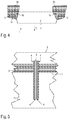
- FIG. 5 shows a view of an injection-molding tool used in the method according to the present disclosure.
- FIG. 1 shows a first composite part 1 , which has been produced according to the inventive method by overmolding with molding material 5 consisting of curable thermosetting material, and functions as a pivot lever in an operating member, wherein the restoring action and a latching feel are formed by the magnetic interaction of pairs of permanent magnets 3 .
- the composite part 1 is formed by overmolding two permanent magnets 3 and associated metal sheets 4 forming a heat-conducting reinforcement for the permanent magnet 3 .
- the permanent magnet 3 is configured in a plate-shaped manner and defines two main surfaces and four end faces, which have a small surface area compared to the main surfaces, and is in each case disposed, with associated metal sheets 4 , in a lateral arm of the composite part 1 .
- Adjacent to the main surfaces are provided the metal sheets 4 of soft magnetic material, which on the one hand serve for guiding and centering the magnetic field but are primarily provided to minimize the heat input into the temperature-sensitive permanent magnets 3 during the overmolding process with the hot molding material 5 , by this heat being removed, due to the good heat conductivity of the metal sheets 4 , via the latter into injection molding tool, which is not shown in FIG. 1 and is in touching contact with the metal sheets.
- FIG. 2 shows a second composite part 1 ′ produced in accordance with the inventive method, which is configured for cooperation with the first composite part 1 of FIG. 1 in an operating member.
- the composite part 1 ′ is formed by overmolding two permanent magnets 3 ′ and associated metal sheets 4 ′ forming a heat-conducting reinforcement of the permanent magnet 3 ′.
- the permanent magnet 3 ′ is in each case configured in a plate-shaped manner and defines two main surfaces and four end faces, which have a small surface area compared to the main surfaces, and is in each case disposed, with associated metal sheets 4 ′, in the composite part 1 ′ configured as a support.
- the metal sheets 4 ′ of soft magnetic material Adjacent to the main surfaces are provided the metal sheets 4 ′ of soft magnetic material, which on the one hand serve for guiding and centering the magnetic field but are primarily provided to minimize the heat input into the temperature-sensitive permanent magnets 3 ′ during the overmolding process with the hot molding material 5 ′, by this heat being removed, due to the good heat conductivity of the metal sheets 4 ′, via the latter into injection molding tool, which is not shown in FIG. 2 and is in touching contact with the metal sheets.
- FIG. 3 shows the operating member formed of the composite parts 1 and 1 ′ of the FIGS. 1 and 2 , respectively.
- the composite part 1 configured and functioning as a pivot lever is disposed opposite to the composite part 1 ′ functioning as a support in such a manner that, in a rest position shown in FIG. 3 , the pairs of the permanent magnet on the side of the pivot lever and the permanent magnet on the side of the support, which are hidden in FIG. 3 , and the associated metal sheets 4 , 4 ′ of the heat-conducting reinforcement are opposite from each other, spaced apart by a minimum distance.
- FIG. 3 shows the operating member formed of the composite parts 1 and 1 ′ of the FIGS. 1 and 2 , respectively.
- the composite part 1 configured and functioning as a pivot lever is disposed opposite to the composite part 1 ′ functioning as a support in such a manner that, in a rest position shown in FIG. 3 , the pairs of the permanent magnet on the side of the pivot lever and the permanent magnet on the side of the support, which are hidden in FIG
- the metal sheets 4 , 4 ′ are provided with associated undercuts 4 a or 4 a ′ and 4 b or 4 b ′ in order to prevent a demolding of the metal sheets 4 or 4 ′ from the molding material 5 or 5 ′ in the direction of the arrows E, E′, and thus in the direction of action of the permanent magnets. Furthermore, the touching contact of the metal sheets 4 and 4 ′ with the respective molding material 5 , 5 ′, which is defined by the surfaces 4 c and 4 d or 4 c ′ and 4 d ′, is minimized to a fraction of the total surface area, whereas the permanent magnets, which are hidden in FIG. 3 and are therefore not shown, are in touching contact with the molding material 5 or 5 ′ only at two end faces.
- FIG. 4 shows another embodiment of a composite part 1 produced in accordance with the present disclosure, which differs from the above-described embodiment merely by the configuration of the undercuts 4 a and 4 b provided for fixation in the molding material 5 , due to them having an arm 4 e that dips into the molding material 5 .
- FIG. 5 shows the injection-molding tool 6 used in the overmolding process of the method according to the present disclosure. It has a mold cavity 7 , also referred to as cavity, into which the hot molding material 5 enters the tool 6 under pressure via an injection machine nozzle that is not shown, in order to form the corresponding composite part in accordance with the mold cavity 7 , after the molding material 5 has solidified.
- a mold cavity 7 also referred to as cavity
- the hot molding material 5 enters the tool 6 under pressure via an injection machine nozzle that is not shown, in order to form the corresponding composite part in accordance with the mold cavity 7 , after the molding material 5 has solidified.
- a step of arranging at least one permanent magnet 3 is disposed in the mold cavity 7 of the injection-molding tool 6 , and two heat conducting sheets 4 extending along the permanent magnet 3 , which form said reinforcement, are disposed at a predefined position in the mold cavity 7 .
- the metal sheets are in touching contact with the injection-molding tool 6 , in order to minimize the heat input into the temperature-sensitive permanent magnet 3 during the overmolding process with the hot molding material 5 , by this heat being removed, due to the good heat conductivity of the metal sheets 4 , via the latter into injection molding tool 6 .
- a thermally insulating intermediate layer 8 in particular an adhesive layer, is provided between the heat-conducting reinforcement 4 and the permanent magnet 3 .
- the intermediate layer 8 is advantageous in that it minimizes the heat input into the permanent magnet 3 , particularly if the contact area between the permanent magnet 3 and the filling material 4 could already be reduced.
- the intermediate layer 8 , and in particular the adhesive layer is advantageous in that the fixing and positioning of the permanent magnet 3 directly on the injection-molding tool can be omitted and that it can instead be positioned and fixed to the injection-molding tool via the reinforcement 4 .
Landscapes
- Engineering & Computer Science (AREA)
- Manufacturing & Machinery (AREA)
- Mechanical Engineering (AREA)
- Power Engineering (AREA)
- Physics & Mathematics (AREA)
- Electromagnetism (AREA)
- Environmental & Geological Engineering (AREA)
- Thermal Sciences (AREA)
- Moulds For Moulding Plastics Or The Like (AREA)
- Injection Moulding Of Plastics Or The Like (AREA)
Abstract
Description
Claims (19)
Applications Claiming Priority (2)
| Application Number | Priority Date | Filing Date | Title |
|---|---|---|---|
| DE102017104895.2A DE102017104895B4 (en) | 2017-03-08 | 2017-03-08 | Shaping process for the production of a composite part having a permanent magnet |
| DE102017104895.2 | 2017-03-08 |
Publications (2)
| Publication Number | Publication Date |
|---|---|
| US20180261386A1 US20180261386A1 (en) | 2018-09-13 |
| US11004601B2 true US11004601B2 (en) | 2021-05-11 |
Family
ID=63259057
Family Applications (1)
| Application Number | Title | Priority Date | Filing Date |
|---|---|---|---|
| US15/905,189 Active 2039-04-05 US11004601B2 (en) | 2017-03-08 | 2018-02-26 | Forming method for producing a composite part having a permanent magnet |
Country Status (3)
| Country | Link |
|---|---|
| US (1) | US11004601B2 (en) |
| CN (1) | CN108568936B (en) |
| DE (1) | DE102017104895B4 (en) |
Families Citing this family (2)
| Publication number | Priority date | Publication date | Assignee | Title |
|---|---|---|---|---|
| EP4499464A1 (en) * | 2022-03-31 | 2025-02-05 | ZF CV Systems Europe BV | A brake valve with a magnet holder for a position sensor |
| CN116252432B (en) * | 2022-12-20 | 2025-07-11 | 嘉善康达斯电子股份有限公司 | Injection molding production equipment for TWS earphone brackets with hardware accessories |
Citations (4)
| Publication number | Priority date | Publication date | Assignee | Title |
|---|---|---|---|---|
| US4638281A (en) * | 1984-11-26 | 1987-01-20 | Max Baermann, G.M.B.H. | Magnetic roll for copy machines and method for manufacturing same |
| DE102004010126A1 (en) | 2003-03-03 | 2004-09-16 | Denso Corp., Kariya | Magnetic sensor and method of manufacturing the same |
| DE102006056799A1 (en) | 2006-12-01 | 2008-06-05 | Efficient Energy Gmbh | Method for producing a workpiece and workpiece |
| DE102007036264A1 (en) | 2007-08-02 | 2009-02-05 | Robert Bosch Gmbh | Method for producing a motion sensor |
Family Cites Families (7)
| Publication number | Priority date | Publication date | Assignee | Title |
|---|---|---|---|---|
| JPH03261537A (en) * | 1990-03-12 | 1991-11-21 | Kubota Corp | Manufacture of pipe |
| US6365078B1 (en) * | 1997-05-30 | 2002-04-02 | Matsushita Electric Industrial Co., Ltd. | Production process for ring shaped resin bonded magnet |
| JP2006035669A (en) * | 2004-07-28 | 2006-02-09 | Matsushita Electric Ind Co Ltd | Insert resin mold |
| JP3786946B1 (en) * | 2005-01-24 | 2006-06-21 | 株式会社三井ハイテック | Permanent magnet resin sealing method |
| JP5900528B2 (en) * | 2014-04-02 | 2016-04-06 | 愛知製鋼株式会社 | Internal magnet type inner rotor manufacturing equipment |
| US9673667B2 (en) * | 2014-07-22 | 2017-06-06 | General Electric Company | System and method for preventing stator permanent magnet demagnetization during vacuum pressure impregnation |
| JP6359758B2 (en) * | 2015-03-23 | 2018-07-18 | 株式会社東芝 | Permanent magnets, motors, and generators |
-
2017
- 2017-03-08 DE DE102017104895.2A patent/DE102017104895B4/en active Active
- 2017-12-27 CN CN201711447933.5A patent/CN108568936B/en active Active
-
2018
- 2018-02-26 US US15/905,189 patent/US11004601B2/en active Active
Patent Citations (4)
| Publication number | Priority date | Publication date | Assignee | Title |
|---|---|---|---|---|
| US4638281A (en) * | 1984-11-26 | 1987-01-20 | Max Baermann, G.M.B.H. | Magnetic roll for copy machines and method for manufacturing same |
| DE102004010126A1 (en) | 2003-03-03 | 2004-09-16 | Denso Corp., Kariya | Magnetic sensor and method of manufacturing the same |
| DE102006056799A1 (en) | 2006-12-01 | 2008-06-05 | Efficient Energy Gmbh | Method for producing a workpiece and workpiece |
| DE102007036264A1 (en) | 2007-08-02 | 2009-02-05 | Robert Bosch Gmbh | Method for producing a motion sensor |
Also Published As
| Publication number | Publication date |
|---|---|
| DE102017104895B4 (en) | 2021-08-19 |
| CN108568936B (en) | 2020-08-18 |
| US20180261386A1 (en) | 2018-09-13 |
| DE102017104895A1 (en) | 2018-09-13 |
| CN108568936A (en) | 2018-09-25 |
Similar Documents
| Publication | Publication Date | Title |
|---|---|---|
| Aliyeva et al. | Recent developments on the overmolding process for the fabrication of thermoset and thermoplastic composites by the integration of nano/micron-scale reinforcements | |
| US7914054B2 (en) | Vehicle latch and method of manufacturing the same | |
| US20180370096A1 (en) | Method for Producing a Plastic Molded Article, Plastic Molded Article and Mold | |
| US20150017390A1 (en) | Molding method for fiber reinforced composite material and molding apparatus for fiber reinforced composite material | |
| KR102339070B1 (en) | Method for the further processing of a prefabricated product, and associated prefabricated product | |
| GB1536913A (en) | Plastics articles and method for manufacturing | |
| US11004601B2 (en) | Forming method for producing a composite part having a permanent magnet | |
| EP3072684A1 (en) | Semi-finished product manufactured from prepreg, three-dimensional preformed body and overmoulded part | |
| US20180361950A1 (en) | Tape-reinforced plastics cladding part and process for the manufacture thereof | |
| JP5950194B2 (en) | Method for producing composite molded body | |
| WO2015033980A1 (en) | Production method for fiber reinforcing member | |
| CA2984054A1 (en) | Resin injection apparatus and method of manufacturing core product | |
| JP6229197B2 (en) | Molded product and manufacturing method thereof | |
| KR102203326B1 (en) | Injection mold for reducing weld-line around hole in vehicle panel | |
| JP5442970B2 (en) | Insert molding method | |
| US20090053457A1 (en) | Insert molded article | |
| KR20190138155A (en) | Forming method of composite material | |
| KR20150114427A (en) | Method for producing injection molded and resin bonded permanent magnets from a thermosetting plastic comprising a particle-shaped magnetic material, method for producing injection molded and resin bonded permanent magnets from a thermosetting plastic comprising a particle-shaped magnetic material, as a two-components-element and injection molded and resin bonded permanent magnets | |
| US10018894B2 (en) | Lens carrier, method for manufacturing a lens carrier, device for manufacturing a lens carrier, and camera system | |
| KR20110139393A (en) | Insert injection molding method and structure of insert for same | |
| US20070290411A1 (en) | Method For Producing A Composite Part By Injection Moulding, Injection Compression Moulding Or Back Compression Moulding Of A Plastic Material | |
| EP3548274B1 (en) | Hybrid fiber based molding thermoplastic article and process of forming same | |
| JP6357833B2 (en) | Manufacturing method of composite molded product | |
| JP6572822B2 (en) | Method for producing fiber reinforced thermoplastic resin structure | |
| JP2006001021A (en) | Appearance part and its manufacturing method |
Legal Events
| Date | Code | Title | Description |
|---|---|---|---|
| AS | Assignment |
Owner name: PREH GMBH, GERMANY Free format text: ASSIGNMENT OF ASSIGNORS INTEREST;ASSIGNORS:KIRSCH, RENE;LANG, KAI;SIGNING DATES FROM 20180212 TO 20180217;REEL/FRAME:045040/0151 |
|
| FEPP | Fee payment procedure |
Free format text: ENTITY STATUS SET TO UNDISCOUNTED (ORIGINAL EVENT CODE: BIG.); ENTITY STATUS OF PATENT OWNER: LARGE ENTITY |
|
| STPP | Information on status: patent application and granting procedure in general |
Free format text: DOCKETED NEW CASE - READY FOR EXAMINATION |
|
| STPP | Information on status: patent application and granting procedure in general |
Free format text: NON FINAL ACTION MAILED |
|
| STPP | Information on status: patent application and granting procedure in general |
Free format text: RESPONSE TO NON-FINAL OFFICE ACTION ENTERED AND FORWARDED TO EXAMINER |
|
| STPP | Information on status: patent application and granting procedure in general |
Free format text: FINAL REJECTION MAILED |
|
| STPP | Information on status: patent application and granting procedure in general |
Free format text: RESPONSE AFTER FINAL ACTION FORWARDED TO EXAMINER |
|
| STPP | Information on status: patent application and granting procedure in general |
Free format text: NOTICE OF ALLOWANCE MAILED -- APPLICATION RECEIVED IN OFFICE OF PUBLICATIONS |
|
| STPP | Information on status: patent application and granting procedure in general |
Free format text: PUBLICATIONS -- ISSUE FEE PAYMENT VERIFIED |
|
| STCF | Information on status: patent grant |
Free format text: PATENTED CASE |
|
| MAFP | Maintenance fee payment |
Free format text: PAYMENT OF MAINTENANCE FEE, 4TH YEAR, LARGE ENTITY (ORIGINAL EVENT CODE: M1551); ENTITY STATUS OF PATENT OWNER: LARGE ENTITY Year of fee payment: 4 |