US11001233B2 - Fluid distribution valve for a vehicle windshield washer liquid distribution system - Google Patents
Fluid distribution valve for a vehicle windshield washer liquid distribution system Download PDFInfo
- Publication number
- US11001233B2 US11001233B2 US15/546,295 US201515546295A US11001233B2 US 11001233 B2 US11001233 B2 US 11001233B2 US 201515546295 A US201515546295 A US 201515546295A US 11001233 B2 US11001233 B2 US 11001233B2
- Authority
- US
- United States
- Prior art keywords
- valve
- wiper
- duct
- membrane
- fluid
- Prior art date
- Legal status (The legal status is an assumption and is not a legal conclusion. Google has not performed a legal analysis and makes no representation as to the accuracy of the status listed.)
- Active, expires
Links
Images


Classifications
-
- B—PERFORMING OPERATIONS; TRANSPORTING
- B60—VEHICLES IN GENERAL
- B60S—SERVICING, CLEANING, REPAIRING, SUPPORTING, LIFTING, OR MANOEUVRING OF VEHICLES, NOT OTHERWISE PROVIDED FOR
- B60S1/00—Cleaning of vehicles
- B60S1/02—Cleaning windscreens, windows or optical devices
- B60S1/46—Cleaning windscreens, windows or optical devices using liquid; Windscreen washers
- B60S1/48—Liquid supply therefor
- B60S1/481—Liquid supply therefor the operation of at least part of the liquid supply being controlled by electric means
- B60S1/482—Liquid supply therefor the operation of at least part of the liquid supply being controlled by electric means combined with the operation of windscreen wipers
-
- B—PERFORMING OPERATIONS; TRANSPORTING
- B60—VEHICLES IN GENERAL
- B60S—SERVICING, CLEANING, REPAIRING, SUPPORTING, LIFTING, OR MANOEUVRING OF VEHICLES, NOT OTHERWISE PROVIDED FOR
- B60S1/00—Cleaning of vehicles
- B60S1/02—Cleaning windscreens, windows or optical devices
- B60S1/46—Cleaning windscreens, windows or optical devices using liquid; Windscreen washers
- B60S1/48—Liquid supply therefor
- B60S1/481—Liquid supply therefor the operation of at least part of the liquid supply being controlled by electric means
-
- B—PERFORMING OPERATIONS; TRANSPORTING
- B60—VEHICLES IN GENERAL
- B60S—SERVICING, CLEANING, REPAIRING, SUPPORTING, LIFTING, OR MANOEUVRING OF VEHICLES, NOT OTHERWISE PROVIDED FOR
- B60S1/00—Cleaning of vehicles
- B60S1/02—Cleaning windscreens, windows or optical devices
- B60S1/46—Cleaning windscreens, windows or optical devices using liquid; Windscreen washers
- B60S1/48—Liquid supply therefor
- B60S1/487—Liquid supply therefor the liquid being heated
- B60S1/488—Liquid supply therefor the liquid being heated electrically
-
- B—PERFORMING OPERATIONS; TRANSPORTING
- B60—VEHICLES IN GENERAL
- B60S—SERVICING, CLEANING, REPAIRING, SUPPORTING, LIFTING, OR MANOEUVRING OF VEHICLES, NOT OTHERWISE PROVIDED FOR
- B60S1/00—Cleaning of vehicles
- B60S1/02—Cleaning windscreens, windows or optical devices
- B60S1/46—Cleaning windscreens, windows or optical devices using liquid; Windscreen washers
- B60S1/48—Liquid supply therefor
- B60S1/52—Arrangement of nozzles; Liquid spreading means
- B60S1/522—Arrangement of nozzles; Liquid spreading means moving liquid spreading means, e.g. arranged in wiper arms
- B60S1/524—Arrangement of nozzles; Liquid spreading means moving liquid spreading means, e.g. arranged in wiper arms arranged in wiper blades
-
- F—MECHANICAL ENGINEERING; LIGHTING; HEATING; WEAPONS; BLASTING
- F16—ENGINEERING ELEMENTS AND UNITS; GENERAL MEASURES FOR PRODUCING AND MAINTAINING EFFECTIVE FUNCTIONING OF MACHINES OR INSTALLATIONS; THERMAL INSULATION IN GENERAL
- F16K—VALVES; TAPS; COCKS; ACTUATING-FLOATS; DEVICES FOR VENTING OR AERATING
- F16K27/00—Construction of housing; Use of materials therefor
- F16K27/02—Construction of housing; Use of materials therefor of lift valves
- F16K27/029—Electromagnetically actuated valves
-
- F—MECHANICAL ENGINEERING; LIGHTING; HEATING; WEAPONS; BLASTING
- F16—ENGINEERING ELEMENTS AND UNITS; GENERAL MEASURES FOR PRODUCING AND MAINTAINING EFFECTIVE FUNCTIONING OF MACHINES OR INSTALLATIONS; THERMAL INSULATION IN GENERAL
- F16K—VALVES; TAPS; COCKS; ACTUATING-FLOATS; DEVICES FOR VENTING OR AERATING
- F16K31/00—Actuating devices; Operating means; Releasing devices
- F16K31/02—Actuating devices; Operating means; Releasing devices electric; magnetic
- F16K31/06—Actuating devices; Operating means; Releasing devices electric; magnetic using a magnet, e.g. diaphragm valves, cutting off by means of a liquid
- F16K31/0603—Multiple-way valves
- F16K31/0641—Multiple-way valves the valve member being a diaphragm
-
- F—MECHANICAL ENGINEERING; LIGHTING; HEATING; WEAPONS; BLASTING
- F16—ENGINEERING ELEMENTS AND UNITS; GENERAL MEASURES FOR PRODUCING AND MAINTAINING EFFECTIVE FUNCTIONING OF MACHINES OR INSTALLATIONS; THERMAL INSULATION IN GENERAL
- F16K—VALVES; TAPS; COCKS; ACTUATING-FLOATS; DEVICES FOR VENTING OR AERATING
- F16K31/00—Actuating devices; Operating means; Releasing devices
- F16K31/02—Actuating devices; Operating means; Releasing devices electric; magnetic
- F16K31/06—Actuating devices; Operating means; Releasing devices electric; magnetic using a magnet, e.g. diaphragm valves, cutting off by means of a liquid
- F16K31/0644—One-way valve
- F16K31/0672—One-way valve the valve member being a diaphragm
-
- F—MECHANICAL ENGINEERING; LIGHTING; HEATING; WEAPONS; BLASTING
- F16—ENGINEERING ELEMENTS AND UNITS; GENERAL MEASURES FOR PRODUCING AND MAINTAINING EFFECTIVE FUNCTIONING OF MACHINES OR INSTALLATIONS; THERMAL INSULATION IN GENERAL
- F16K—VALVES; TAPS; COCKS; ACTUATING-FLOATS; DEVICES FOR VENTING OR AERATING
- F16K7/00—Diaphragm valves or cut-off apparatus, e.g. with a member deformed, but not moved bodily, to close the passage ; Pinch valves
- F16K7/02—Diaphragm valves or cut-off apparatus, e.g. with a member deformed, but not moved bodily, to close the passage ; Pinch valves with tubular diaphragm
- F16K7/04—Diaphragm valves or cut-off apparatus, e.g. with a member deformed, but not moved bodily, to close the passage ; Pinch valves with tubular diaphragm constrictable by external radial force
- F16K7/045—Diaphragm valves or cut-off apparatus, e.g. with a member deformed, but not moved bodily, to close the passage ; Pinch valves with tubular diaphragm constrictable by external radial force by electric or magnetic means
-
- F—MECHANICAL ENGINEERING; LIGHTING; HEATING; WEAPONS; BLASTING
- F16—ENGINEERING ELEMENTS AND UNITS; GENERAL MEASURES FOR PRODUCING AND MAINTAINING EFFECTIVE FUNCTIONING OF MACHINES OR INSTALLATIONS; THERMAL INSULATION IN GENERAL
- F16K—VALVES; TAPS; COCKS; ACTUATING-FLOATS; DEVICES FOR VENTING OR AERATING
- F16K7/00—Diaphragm valves or cut-off apparatus, e.g. with a member deformed, but not moved bodily, to close the passage ; Pinch valves
- F16K7/12—Diaphragm valves or cut-off apparatus, e.g. with a member deformed, but not moved bodily, to close the passage ; Pinch valves with flat, dished, or bowl-shaped diaphragm
- F16K7/123—Diaphragm valves or cut-off apparatus, e.g. with a member deformed, but not moved bodily, to close the passage ; Pinch valves with flat, dished, or bowl-shaped diaphragm the seat being formed on the bottom of the fluid line
Definitions
- the present invention concerns a fluid distribution valve in particular for a vehicle windshield washer liquid distribution system.
- each of the wipers including one or two windshield washer liquid sprayer manifolds.
- the manifold extends on one side of the wiper to spray windshield washer liquid onto the windshield.
- the liquid is generally sprayed ahead of the moving wiper so as to be wiped immediately and not interfere with the driver's view. For example, the liquid is sprayed in the upward direction and spraying is stopped for the movement of the arm in the downward direction.
- the water can be sprayed behind the wiper, to allow the liquid time to interact with the pollutants that have to be eliminated.
- the supply of windshield washer liquid to the manifold necessitates a pipe feeding the liquid to the manifold from a single-channel pump taking the windshield washer liquid from a windshield washer liquid tank disposed under the hood of the vehicle.
- a wiper including two manifolds (bi-manifold), there is a manifold on each side of the wiper.
- These manifolds are designed to spray the windshield washer liquid onto the windshield alternately in the upward direction and the downward direction of rotation of the wiper.
- the supply of windshield washer liquid to these manifolds necessitates two separate pipes feeding the liquid to the manifolds from a two-channel pump taking up liquid from the tank.
- installing these two pipes as far as the sprayer manifolds is relatively complicated, in particular at the level of the wiper drive arms along which the available interior space is small.
- the two visible pipes on the arm are often perceived as relatively unaesthetic, there being also a requirement to improve the visual appearance of the liquid supply arrangement.
- the two pipes also have a negative impact on aerodynamic performance.
- wiper systems have already been proposed in which the two sprayer manifolds are connected to a single pipe enabling said manifolds to be fed from a single-channel pump.
- the windshield washer liquid is distributed into one and/or the other of said sprayer manifolds by at least one valve directing the windshield washer liquid into the selected sprayer manifold or manifolds.
- the invention aims in particular to improve this technology by means of a new type of valve that makes it possible for example to distribute the windshield washer liquid from a single-channel pump to one or two (or even more) sprayer manifolds.
- this new type of pump is not limited to this particular application and can be used in any application necessitating distribution of fluid.
- the invention proposes a fluid distribution valve, in particular for a vehicle windshield washer liquid distribution system, characterized in that it comprises a body defining a duct for the passage of fluid and including at least one fluid inlet and at least one fluid outlet, a membrane housed in the duct and configured to be deformed by a magnetic field between a first position of at least partial closure of the duct and a second position of at least partial opening of the duct, and means for generating a magnetic field inside the duct in order to control the deformation of the membrane.
- the valve according to the invention is therefore controlled by means of a magnetic field, the application of that magnetic field inducing a movement of the membrane. This technology advantageous makes it possible to circumvent the mechanical constraints.
- At least partial closure (respectively opening) of the duct means the closure (respectively opening) of at least one inlet or outlet of the duct.
- the membrane can be configured to block at least part of the duct, in particular at least one outlet of the duct, in its first position, corresponding to the absence of an applied magnetic field. In this first position, the membrane can have a profile of non-plane shape.
- the membrane On application of the magnetic field, the membrane is deformed and adopts a position in accordance with the field lines termed the second position.
- the membrane In this second position the membrane can be at least in part pressed against an internal wall of the duct. It can have a profile of substantially plane shape in this second position.
- the membrane is preferably made from a flexible material and is for example made from a polymer material, notably from silicone.
- this membrane contains magnetic particles.
- the magnetic particles When acted on by the magnetic field generated by said means the magnetic particles are able to deform the membrane.
- the application of the magnetic field can therefore lead to deformation of the membrane and opening or closing of the duct.
- the particles carried by the membrane will become aligned with the field lines on application of the magnetic field and will lead to the deformation of the membrane and its movement from one position to another.
- the membrane may be fixed to an internal wall of the duct.
- the means for generating the magnetic field preferably comprise a winding of at least one electrical wire around the part of the duct housing the membrane.
- This winding forms a coil—or solenoid—that is intended to be connected to a power supply.
- the valve according to the invention can therefore be considered a solenoid valve. It is the flow of current in the winding that induces a magnetic field.
- This winding can be configured to generate heat for heating the fluid. This is advantageous if there is a risk of the fluid freezing.
- the valve can be integrated into a fluid pipe.
- the valve is connected to a pipe of this kind.
- the fluid inlet includes a connector for connecting it to the feed pipe coming from the pump and/or the fluid outlet includes a connector for connecting it to a sprayer manifold.
- sprayer manifold is meant any vehicle windshield washer liquid sprayer device known to a person skilled in the art, and the sprayer manifold includes a plurality of sprayer nozzles, for example.
- the manifold is a simple nozzle.
- the present invention consists in a hydraulic connector for a vehicle windshield washer liquid distribution system comprising at least one valve according to the invention.
- the present invention consists in a vehicle windshield washer liquid distribution system comprising at least one valve as described above.
- the present invention also concerns a vehicle windshield wiper system comprising at least one valve as described above.
- That system may comprise a pump, for example a single-channel pump, at least one wiper and at least one sprayer manifold connected to the pump by said valve.
- the latter is situated on the wiper, for example.
- valve In the case of a mono-manifold wiper the valve has an inlet connected to the pump and an outlet connected to the manifold and is termed a two-port valve. In the case of a bi-manifold wiper the valve is of the three-port type and has an inlet connected to the pump and two outlets connected to respective manifolds.
- the valve may be integrated into means for connecting the wiper to a drive arm of said wiper.
- the valve is integrated into an end fitting of the wiper.
- the wiper system also comprises a wiper drive arm on which the sprayer manifold is situated, for example.
- valve is used to feed nozzles or manifolds integrated into a wiper arm and functions on the same principle to control spraying.
- the present invention also concerns a system for cleaning a motor vehicle driver assistance device, in particular imaging means or electromagnetic detection means, said system comprising at least one fluid distribution valve according to any of the above definitions.
- imaging means is meant for example a video camera
- electromagnétique detection means is meant for example radar or lidar means.
- Sensors are fitted to an increasingly large number of motor vehicles in order to assist the driver of the vehicle in certain driving situations, one well known instance of which is assisting parking.
- the images supplied by the imaging means or the data transmitted by the radar for example, must be of the best possible quality and it is therefore essential for the faces of these sensors facing toward the exterior of the vehicle to be clean.
- a device for cleaning the sensor may be associated with the sensor and controlled so as to inject a flow of cleaning fluid onto said sensor before detection occurs. It is beneficial to control the device to determine the start and the duration of the cleaning sequence and if necessary to be able to retract the cleaning device after use, in order for it not to impede detection when the sensors are operating, and in order to protect them from impacts, for example. Moreover, it must be as compact as possible to satisfy constraints on the overall size of the vehicle. It is moreover a requirement that such devices enable the injection of different fluids, whether gases or liquids.
- a cleaning liquid is sprayed onto the sensor, for example the lens of an imaging video camera, to expel dirt from it, it is beneficial to dry that lens quickly in order to prevent any risk of pollution of the images by any traces that such a liquid may leave behind (droplets, streaks, etc.).
- Equipping a driving assistance device of this kind with a cleaning system of this kind comprising a valve according to the invention is therefore particularly advantageous, the latter valve being compact and if necessary controllable directly by a magnetic field generated by an electric current for supplying power to said driver assistance device. This avoids the requirement for additional means to control the valve according to the invention.
- the present invention further concerns a vehicle, in particular a motor vehicle, characterized in that it comprises at least one valve or one system as described above.
- the present invention further concerns a method of controlling a fluid distribution valve, in particular for a vehicle windshield wiper system, characterized in that it comprises a step of generating a magnetic field inside a duct of the valve in order to move a membrane housed in said duct from a first position of at least partial closure of the duct to a second position of at least partial opening of the duct.
- FIG. 1 is a diagram showing a vehicle windshield wiper system
- FIG. 2 is a perspective view of a wiper of a vehicle windshield wiper system
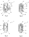
- FIGS. 3 and 4 are diagrams showing in axial section two different positions of a valve according to the invention for a bi-manifold wiper
- FIGS. 5 and 6 are diagrams in axial section similar to FIGS. 3 and 4 and showing a variant embodiment of the valve according to the invention for a mono-manifold wiper.
- longitudinal and lateral refer to the orientation of the drive arm on which the wiper is mounted.
- the longitudinal direction corresponds to the main axis of the arm along which it extends and the lateral orientations correspond to straight line segments that are concurrent, i.e. that cross the longitudinal direction, notably perpendicularly to the longitudinal axis of the arm in its plane of rotation.
- front and rear are to be understood relative to the point at which the wiper is fixed to the arm, the term front designating the direction from the distal end of the arm and the term rear the opposite direction.
- the directions referred to as upper or lower correspond to orientations perpendicular to the plane of rotation of the arm, the term lower containing the plane of the windshield.
- FIG. 1 which shows a system 1 for wiping the windshield 3 of a motor vehicle, that system here including a bi-manifold wiper 5 for wiping the windshield 3 that is shown detached from a drive arm 7 .
- the wiper 5 includes two windshield washer liquid sprayer manifolds 9 mounted on the wiper.
- the wiper system 1 further comprises windshield washer liquid supply means that comprise a valve 11 according to the invention for selective distribution of windshield washer liquid to each of the manifolds 9 , a windshield washer liquid feed pump 15 and a feed pipe for feeding the windshield washer liquid from the pump 15 to the valve 11 .
- the valve 11 is connected to the manifolds 9 by two pipes 17 .
- the wiper system 1 includes a single wiper 5 disposed substantially at the center of the windshield 3 .
- the wiper system 1 could alternatively include two wipers, one disposed facing the driver and one disposed facing the passenger.
- the manifolds 9 extend substantially over the length of the wiper, on each side and on its longitudinal axis. These manifolds 9 are therefore adapted to spray the windshield washer liquid along the wiper.
- the wiper 5 is mounted on the drive arm 7 so that it can be driven by the latter to wipe the windshield 3 with a cyclic rotation movement over the windshield substantially in part of a circle about a rotation axis 19 .
- the pump 15 for feeding the manifolds 9 with windshield washer liquid is itself connected to the valve 11 by means of the feed pipe 13 , which here is a flexible pipe, and to a windshield washer liquid container 21 from which the liquid is taken to be fed to the manifolds 9 .
- the feed pipe 13 and an electrical power supply cable 25 of the valve 11 are for example housed at least in part in the arm 7 and in part under the hood 23 of the vehicle.
- the valve 11 according to the invention can be mounted at the distal end 31 of the arm 7 , for example at the level of an arm headpiece.
- the valve 11 is preferably at least in part integrated into a hydraulic connector 33 configured to establish a hydraulic connection of the valve 11 to the manifolds 9 , as seen in FIG. 2 , so that at least its two outlets are configured to form part of the hydraulic connector intended to be connected to the wiper.
- the hydraulic connector 33 is disposed on the arm 7 , not shown in FIG. 2 .
- the wiper 5 further includes a mechanical connector 35 and an adapter 36 articulated to the mechanical connector and configured to be locked onto the arm 7 .
- valve 11 and the pump 15 are connected to a control unit 37 which is for example the body controller of the vehicle, forming means for combined control of the valve and the pump.
- This control unit 37 can manage the operation of the valve 11 and the pump 15 in accordance with a plurality of distinct operating modes. One of those modes can provide in a cleaning cycle continuous activation of the pump 15 and selective control of the valve 11 as a function of the various positions of the wiper 5 on the windshield 3 in an associated wiping cycle.
- FIGS. 3 and 4 are diagrams showing a first embodiment of the valve 11 according to the invention.
- the valve 11 comprises a body 41 defining a duct 43 for the windshield washer liquid and here including an inlet 45 and two outlets 47 , 49 .
- the first outlet 47 is for example aligned with the inlet and the second outlet 49 is lateral and here is substantially perpendicular to the inlet 45 , the duct 43 therefore being substantially T-shaped.
- the inlet 45 of the valve is connected by the pipe 13 to the pump 15 and the outlets 47 , 49 of the valve are connected to the respective pipes 17 .
- the body 41 comprises a main part 41 a defining the inlet 45 and the first outlet 47 and a branch 41 b that defines the second outlet 49 .
- the main part 41 a of the body is surrounded by a winding 51 consisting of electrical wire(s) that forms a coil or solenoid and is connected to a power supply, not shown, via the power supply cable 25 of the control unit 37 .
- This winding 51 can take the form of one or more layers of electrical wire on the part 41 a of the body. Alternatively, the winding 51 can be integrated into the body 41 of the valve so as to extend around the duct 43 over a part of its length.
- the valve 11 further comprises a membrane 53 mobile between a first position of at least partial closure of the duct 43 ( FIG. 3 ) and a second position of at least partial opening of the duct ( FIG. 4 ).
- the T-shape of the duct of a three-channel valve is not limiting on the invention.
- the inlet and the two outlets can therefore form a Y or any other shape appropriate to the shape of the mobile membrane and to the integration of the valve into the system.
- the membrane 53 When the membrane 53 is in its second position it blocks the second outlet 49 of the duct and leaves its first outlet 47 free.
- the pump 15 When the pump 15 is activated the windshield washer liquid flows from the inlet 45 toward the first outlet 47 of the valve to supply windshield washer liquid to the other manifold 9 of the wiper 5 as shown by the arrow 57 .
- the membrane 53 is deformed between the first and second positions by application of a magnetic field in the duct 43 and in particular in the part of the duct housing the membrane.
- the membrane 53 is housed in the main part 41 a of the duct.
- the membrane 53 in the absence of an applied magnetic field, the membrane 53 is in the first position shown in FIG. 3 .
- the membrane 53 is deformed and adopts the second position shown in FIG. 4 .
- the membrane 53 is made from a supple or flexible material (such as a polymer material) and contains magnetic particles that are intended, when acted on by the magnetic field, to deform the membrane and to move it from its first position to its second position.
- the particles carried by the membrane are aligned parallel to the field lines 59 , which deforms the membrane 53 .
- the membrane 53 is fixed substantially at its center to the internal wall of the main part 41 a of the body. It comprises an upstream part 61 (in relation to the direction of flow of the liquid in the duct 43 ) that can be deformed between a position in which it is applied to the peripheral edge of the mouth 63 of the second outlet 49 in the duct and therefore blocks that outlet 49 ( FIG. 4 ) and a position in which its free end contacts an internal surface of the duct 43 situated facing the mouth 63 and therefore blocks the first outlet 47 ( FIG. 3 ).
- the membrane 53 also comprises a downstream part 65 that can be deformed between a position in which it is applied to an internal surface of the duct 43 situated on the same side as the mouth 63 and therefore leaves the first outlet 47 free ( FIG. 4 ) and a position in which its free end contacts an internal surface of the duct situated on the side opposite the mouth 63 and therefore blocks the first outlet 47 ( FIG. 3 ).
- the membrane 53 In its position represented in FIG. 3 the membrane 53 has the shape of a U or a V with a median part fixed to the internal wall of the duct 43 and the branches of which form the aforementioned upstream part 61 and downstream part 65 , respectively. In the position shown in FIG. 4 the membrane 53 has a substantially plane shape.
- the general shape of the membrane 53 depends in particular on the shape in section of the duct 43 .
- the membrane 53 can have a rectangular general shape.
- the membrane 53 can then be designed to be pressed against a plane internal face of the duct 43 in FIG. 4 and its upstream part 61 and downstream part 65 can each be configured so that its peripheral edges cooperate in fluid-tight manner with the other internal faces of the duct in FIG. 3 .
- the upstream part 61 and the downstream part 65 of the membrane 53 can each have a circular or oblong general shape.
- the wiper system 1 and the valve 11 from FIGS. 3 and 4 can operate in the following manner.
- the control unit 37 activates the pump 15 , which feeds the valve with windshield washer liquid from the container 21 .
- the winding 51 of the valve 11 can at this stage remain unenergized so that the membrane 53 remains in the first position shown in FIG. 3 , in which case the windshield washer liquid feeds the manifold of the wiper connected to the second outlet 49 , for example during rotation of the wiper in the upward direction.
- the control unit 37 then activates the valve 11 , i.e. activates the supply of electrical power to the winding 51 .
- the membrane 53 is then moved into the second position shown in FIG. 4 so that the windshield washer liquid flows to the manifold of the wiper connected to the first outlet 47 , for example during rotation of the wiper in the downward direction.
- FIGS. 5 and 6 show a variant embodiment of the valve according to the invention, this valve 11 including an inlet 45 and only one outlet 47 and therefore being of the two-port type, which can be used to feed washer liquid to a mono-manifold wiper.
- the references used in relation to FIGS. 3 and 4 are used again to designate the same elements in FIGS. 5 and 6 .
- FIGS. 3 and 4 The essential structural difference between the embodiments of FIGS. 3 and 4 on the one hand and FIGS. 5 and 6 on the other hand is that the body 41 of the valve does not include a branch. In its first position shown in FIG. 5 , the membrane 53 completely blocks the duct 43 and in its second position shown in FIG. 6 it leaves the duct 43 free.
- the control unit 37 can command simultaneous activation of the pump 15 and the valve 11 from FIGS. 5 and 6 , windshield washer liquid then flowing from the container 21 to the single manifold of the wiper via the duct 43 of the valve 11 .
- the invention is not limited to the examples that have just been described.
Landscapes
- Engineering & Computer Science (AREA)
- General Engineering & Computer Science (AREA)
- Mechanical Engineering (AREA)
- Water Supply & Treatment (AREA)
- Physics & Mathematics (AREA)
- Electromagnetism (AREA)
- Magnetically Actuated Valves (AREA)
- Cleaning By Liquid Or Steam (AREA)
- Multiple-Way Valves (AREA)
- Details Of Valves (AREA)
- Body Structure For Vehicles (AREA)
- Lift Valve (AREA)
- Nozzles (AREA)
Abstract
Description
Claims (13)
Applications Claiming Priority (3)
| Application Number | Priority Date | Filing Date | Title |
|---|---|---|---|
| FR1550729A FR3032162B1 (en) | 2015-01-30 | 2015-01-30 | FLUID DISPENSING VALVE FOR A VEHICLE WASHER LIQUID DISPENSING SYSTEM |
| FR1550729 | 2015-01-30 | ||
| PCT/EP2015/080237 WO2016119974A1 (en) | 2015-01-30 | 2015-12-17 | Fluid distribution valve for a vehicle washer fluid distribution system |
Publications (2)
| Publication Number | Publication Date |
|---|---|
| US20170369037A1 US20170369037A1 (en) | 2017-12-28 |
| US11001233B2 true US11001233B2 (en) | 2021-05-11 |
Family
ID=52779913
Family Applications (1)
| Application Number | Title | Priority Date | Filing Date |
|---|---|---|---|
| US15/546,295 Active 2036-10-24 US11001233B2 (en) | 2015-01-30 | 2015-12-17 | Fluid distribution valve for a vehicle windshield washer liquid distribution system |
Country Status (7)
| Country | Link |
|---|---|
| US (1) | US11001233B2 (en) |
| EP (1) | EP3250422B1 (en) |
| JP (1) | JP6804457B2 (en) |
| KR (1) | KR20170117443A (en) |
| CN (1) | CN107206972B (en) |
| FR (1) | FR3032162B1 (en) |
| WO (1) | WO2016119974A1 (en) |
Families Citing this family (6)
| Publication number | Priority date | Publication date | Assignee | Title |
|---|---|---|---|---|
| JP6774602B2 (en) * | 2017-02-23 | 2020-10-28 | 株式会社Jvcケンウッド | Foreign matter removal device and camera device equipped with it |
| SE542082C2 (en) * | 2017-05-02 | 2020-02-18 | Husqvarna Ab | Valve, use of such valve, separator comprising such valve and method of cleaning a separator body |
| DE102018212050A1 (en) * | 2018-07-19 | 2020-01-23 | Robert Bosch Gmbh | Wiper blade device |
| DE102019217192A1 (en) * | 2019-11-07 | 2021-05-12 | Robert Bosch Gmbh | Wiper blade adapter device, wiper blade with the wiper blade adapter device and windshield wiper with the wiper blade |
| WO2023006997A1 (en) * | 2021-07-30 | 2023-02-02 | Valeo Systèmes d'Essuyage | Wiper with element for spraying cleaning fluid |
| US20250196815A1 (en) * | 2023-12-15 | 2025-06-19 | Aurora Operations, Inc. | High Pressure Sensor Cleaning Nozzles |
Citations (17)
| Publication number | Priority date | Publication date | Assignee | Title |
|---|---|---|---|---|
| JPS5036116U (en) | 1973-07-27 | 1975-04-16 | ||
| DE2638879A1 (en) | 1976-08-28 | 1978-03-02 | Daimler Benz Ag | Check valve with elastomeric membrane closure member - has permanent magnet mounted in plastics wall to bias closure against seat |
| US4520227A (en) * | 1982-03-06 | 1985-05-28 | Robert Bosch Gmbh | Strain relief connection between a housing and an electric conductor assembly |
| JPH0270556A (en) | 1988-02-25 | 1990-03-09 | Trico Folberth Ltd | Window washer device |
| US4969424A (en) | 1989-06-21 | 1990-11-13 | General Motors Corporation | Electromagnetic diaphragm valve |
| US5118071A (en) * | 1988-11-01 | 1992-06-02 | Dr. Huelle Energie, Engineering Gmbh | Electronically driven control valve |
| US5383602A (en) * | 1991-05-25 | 1995-01-24 | Swf Auto-Electric Gmbh | Wiper and washing system, especially for window panes of motor vehicles |
| JPH09286307A (en) | 1996-04-22 | 1997-11-04 | Fuji Heavy Ind Ltd | Window washer liquid rapid heating device |
| DE19860753A1 (en) * | 1998-04-08 | 1999-10-14 | Bitron Ind Espana Sa | Electromagnetic valve for proportional control of volumetric flow, e.g. gaseous media |
| US5996964A (en) * | 1997-05-19 | 1999-12-07 | Q-Core Ltd. | Magnetic flow controller |
| US20040265150A1 (en) * | 2003-05-30 | 2004-12-30 | The Regents Of The University Of California | Magnetic membrane system |
| JP2005014787A (en) | 2003-06-26 | 2005-01-20 | Fuji Electric Holdings Co Ltd | Window washer device and window washer liquid heating device |
| US20120066857A1 (en) * | 2010-09-22 | 2012-03-22 | Webert Christopher A | Beam blade windshield wiper assembly having a fluid manifold mounting system |
| FR2967954A1 (en) | 2010-11-29 | 2012-06-01 | Peugeot Citroen Automobiles Sa | Distribution circuit for distributing washing fluid to vehicle i.e. automobile, has membrane comprising valve member, where membrane returns to rest position to obstruct passage of washing fluid to pipe sections when pump is stopped |
| US20120272471A1 (en) | 2009-12-19 | 2012-11-01 | Daimler Ag | Wiper Arrangement and Method for Operating a Wiper Arrangement for a Motor Vehicle |
| FR2994148A1 (en) | 2012-07-31 | 2014-02-07 | Valeo Systemes Dessuyage | Device for supplying washing liquid to windscreen wiper system of vehicle i.e. car, has distribution unit selectively distributing washing liquid toward projection devices, and control unit controlling pump and distribution unit |
| JP2014073826A (en) | 2012-09-11 | 2014-04-24 | Asmo Co Ltd | Cleaning device for vehicle |
Family Cites Families (8)
| Publication number | Priority date | Publication date | Assignee | Title |
|---|---|---|---|---|
| JPS58118062U (en) * | 1982-02-08 | 1983-08-11 | トヨタ自動車株式会社 | Vehicle cleaning liquid injection device |
| JPS61165254U (en) * | 1985-04-02 | 1986-10-14 | ||
| JP2738054B2 (en) * | 1989-09-18 | 1998-04-08 | 横河電機株式会社 | Micro valve |
| JP2007298126A (en) * | 2006-05-01 | 2007-11-15 | Shimadzu Corp | Valve mechanism and flow path substrate |
| EP1918167A1 (en) * | 2006-10-30 | 2008-05-07 | Valeo Systèmes d'Essuyage | A device for attachment to a wiper blade |
| US7596828B2 (en) * | 2007-08-27 | 2009-10-06 | Evdokimo Arnold W | Multiple blade windshield wiper |
| EP2106978B1 (en) * | 2008-03-31 | 2017-03-08 | Federal-Mogul S.A. | Windscreen wiper device comprising an elastic, elongated carrier element, as well as an elongated wiper blade of a flexible material, which can be placed in abutment with the windscreen to be wiped |
| JP5803831B2 (en) * | 2012-07-23 | 2015-11-04 | 株式会社デンソー | In-vehicle optical sensor cleaning device |
-
2015
- 2015-01-30 FR FR1550729A patent/FR3032162B1/en active Active
- 2015-12-17 EP EP15817225.4A patent/EP3250422B1/en active Active
- 2015-12-17 KR KR1020177024007A patent/KR20170117443A/en not_active Withdrawn
- 2015-12-17 CN CN201580075097.5A patent/CN107206972B/en active Active
- 2015-12-17 US US15/546,295 patent/US11001233B2/en active Active
- 2015-12-17 WO PCT/EP2015/080237 patent/WO2016119974A1/en not_active Ceased
- 2015-12-17 JP JP2017540212A patent/JP6804457B2/en active Active
Patent Citations (20)
| Publication number | Priority date | Publication date | Assignee | Title |
|---|---|---|---|---|
| JPS5036116U (en) | 1973-07-27 | 1975-04-16 | ||
| DE2638879A1 (en) | 1976-08-28 | 1978-03-02 | Daimler Benz Ag | Check valve with elastomeric membrane closure member - has permanent magnet mounted in plastics wall to bias closure against seat |
| US4520227A (en) * | 1982-03-06 | 1985-05-28 | Robert Bosch Gmbh | Strain relief connection between a housing and an electric conductor assembly |
| JPH0270556A (en) | 1988-02-25 | 1990-03-09 | Trico Folberth Ltd | Window washer device |
| US5016312A (en) * | 1988-02-25 | 1991-05-21 | Trico Products Corporation | Washer arrangement for a windscreen wiper |
| US5118071A (en) * | 1988-11-01 | 1992-06-02 | Dr. Huelle Energie, Engineering Gmbh | Electronically driven control valve |
| US4969424A (en) | 1989-06-21 | 1990-11-13 | General Motors Corporation | Electromagnetic diaphragm valve |
| US5383602A (en) * | 1991-05-25 | 1995-01-24 | Swf Auto-Electric Gmbh | Wiper and washing system, especially for window panes of motor vehicles |
| JPH09286307A (en) | 1996-04-22 | 1997-11-04 | Fuji Heavy Ind Ltd | Window washer liquid rapid heating device |
| US5996964A (en) * | 1997-05-19 | 1999-12-07 | Q-Core Ltd. | Magnetic flow controller |
| FR2777340A1 (en) | 1998-04-08 | 1999-10-15 | Bitron Ind Espana | SOLENOID VALVE FOR FLOW REGULATION BY DIRECT EFFECT MEMBRANE |
| DE19860753A1 (en) * | 1998-04-08 | 1999-10-14 | Bitron Ind Espana Sa | Electromagnetic valve for proportional control of volumetric flow, e.g. gaseous media |
| US20040265150A1 (en) * | 2003-05-30 | 2004-12-30 | The Regents Of The University Of California | Magnetic membrane system |
| JP2005014787A (en) | 2003-06-26 | 2005-01-20 | Fuji Electric Holdings Co Ltd | Window washer device and window washer liquid heating device |
| US20120272471A1 (en) | 2009-12-19 | 2012-11-01 | Daimler Ag | Wiper Arrangement and Method for Operating a Wiper Arrangement for a Motor Vehicle |
| JP2013514920A (en) | 2009-12-19 | 2013-05-02 | ダイムラー・アクチェンゲゼルシャフト | Wiper for automobile and operation method of wiper |
| US20120066857A1 (en) * | 2010-09-22 | 2012-03-22 | Webert Christopher A | Beam blade windshield wiper assembly having a fluid manifold mounting system |
| FR2967954A1 (en) | 2010-11-29 | 2012-06-01 | Peugeot Citroen Automobiles Sa | Distribution circuit for distributing washing fluid to vehicle i.e. automobile, has membrane comprising valve member, where membrane returns to rest position to obstruct passage of washing fluid to pipe sections when pump is stopped |
| FR2994148A1 (en) | 2012-07-31 | 2014-02-07 | Valeo Systemes Dessuyage | Device for supplying washing liquid to windscreen wiper system of vehicle i.e. car, has distribution unit selectively distributing washing liquid toward projection devices, and control unit controlling pump and distribution unit |
| JP2014073826A (en) | 2012-09-11 | 2014-04-24 | Asmo Co Ltd | Cleaning device for vehicle |
Non-Patent Citations (6)
| Title |
|---|
| Communication from the Examining Division and Annex to the Communication in corresponding European Application No. 15 817 225.4, dated Jul. 29, 2019 (4 pages). |
| International Search Report issued in PCT/EP2015/080237 dated Mar. 14, 2016 (3 pages). |
| Machine translation of description portion of French publication 2967954, published Jun. 2012 (Year: 2012). * |
| Machine translation of description portion of German publication 19860753, published Oct. 1999 (Year: 1999). * |
| Notice of Reason for Rejection in corresponding Japanese Application No. 2017-540212, dated Aug. 30, 2019 (16 pages). |
| Written Opinion of the International Searching Authority issued in PCT/EP2015/080237 dated Mar. 14, 2016 (5 pages). |
Also Published As
| Publication number | Publication date |
|---|---|
| KR20170117443A (en) | 2017-10-23 |
| JP6804457B2 (en) | 2020-12-23 |
| FR3032162B1 (en) | 2017-02-17 |
| CN107206972B (en) | 2021-07-27 |
| JP2018508721A (en) | 2018-03-29 |
| EP3250422A1 (en) | 2017-12-06 |
| WO2016119974A1 (en) | 2016-08-04 |
| FR3032162A1 (en) | 2016-08-05 |
| EP3250422B1 (en) | 2021-06-30 |
| US20170369037A1 (en) | 2017-12-28 |
| CN107206972A (en) | 2017-09-26 |
Similar Documents
| Publication | Publication Date | Title |
|---|---|---|
| US11001233B2 (en) | Fluid distribution valve for a vehicle windshield washer liquid distribution system | |
| US8832900B2 (en) | Windshield washer system | |
| EP2873571B1 (en) | Vehicle-mounted-camera cleaning device | |
| CN110214102B (en) | Vehicle washing system and vehicle provided with same | |
| JP4513889B2 (en) | Camera with washer nozzle and washer nozzle | |
| US11377073B2 (en) | System for cleaning an optical sensor, assembly comprising such a system, and associated motor vehicle | |
| CN104470771B (en) | Vehicle-mounted camera cleaning device and vehicle-mounted camera cleaning method | |
| EP2873570B1 (en) | Vehicle-mounted-camera cleaning device | |
| CN105480202B (en) | Windshield wiper, system and method for wiping a glass surface of a motor vehicle | |
| JP2012035654A (en) | Nozzle device for on-board camera, on-board camera with cleaning device, and cleaning system for on-board camera | |
| EP4196374B1 (en) | Cleaning device, cleaning device system and vehicle with a sensoric system comprising at least a sensor for automated driving and method of spray cleaning of a sensor surface with the cleaning device | |
| CN109383456B (en) | System for cleaning glass surfaces of vehicles | |
| CN109383457B (en) | System for cleaning glass surfaces of vehicles | |
| CN105799657B (en) | The wiper blade of integrated washer nozzle | |
| CN111032451A (en) | License plate lamp unit and vehicle with license plate lamp unit | |
| CN110167800A (en) | Vehicle sensor cleaning device | |
| CN104386029A (en) | Self-cleaning automobile rearview | |
| KR101417490B1 (en) | Apparatus for supplying washer liquid of vehicle | |
| US20240317184A1 (en) | Method for cleaning motor vehicle surfaces | |
| EP3210841A1 (en) | Blade connector, wiper blade and wiper device for a vehicle | |
| CN217320300U (en) | Cleaning device | |
| JP5876355B2 (en) | Window washer equipment | |
| CN217048561U (en) | Fluid distribution assemblies for sensors used in cleaning vehicles and motor vehicles | |
| JP2024509138A (en) | Device for cleaning glass surfaces | |
| CN221718501U (en) | Cleaning agent supply device, washing system and vehicle |
Legal Events
| Date | Code | Title | Description |
|---|---|---|---|
| AS | Assignment |
Owner name: VALEO SYSTEMES D'ESSUYAGE, FRANCE Free format text: ASSIGNMENT OF ASSIGNORS INTEREST;ASSIGNOR:CAILLOT, GERALD;REEL/FRAME:043100/0796 Effective date: 20170712 |
|
| STPP | Information on status: patent application and granting procedure in general |
Free format text: DOCKETED NEW CASE - READY FOR EXAMINATION |
|
| STPP | Information on status: patent application and granting procedure in general |
Free format text: NON FINAL ACTION MAILED |
|
| STPP | Information on status: patent application and granting procedure in general |
Free format text: RESPONSE TO NON-FINAL OFFICE ACTION ENTERED AND FORWARDED TO EXAMINER |
|
| STPP | Information on status: patent application and granting procedure in general |
Free format text: FINAL REJECTION MAILED |
|
| STPP | Information on status: patent application and granting procedure in general |
Free format text: DOCKETED NEW CASE - READY FOR EXAMINATION |
|
| STPP | Information on status: patent application and granting procedure in general |
Free format text: NON FINAL ACTION MAILED |
|
| STPP | Information on status: patent application and granting procedure in general |
Free format text: RESPONSE TO NON-FINAL OFFICE ACTION ENTERED AND FORWARDED TO EXAMINER |
|
| STPP | Information on status: patent application and granting procedure in general |
Free format text: NOTICE OF ALLOWANCE MAILED -- APPLICATION RECEIVED IN OFFICE OF PUBLICATIONS |
|
| STPP | Information on status: patent application and granting procedure in general |
Free format text: PUBLICATIONS -- ISSUE FEE PAYMENT RECEIVED |
|
| STPP | Information on status: patent application and granting procedure in general |
Free format text: PUBLICATIONS -- ISSUE FEE PAYMENT VERIFIED |
|
| STCF | Information on status: patent grant |
Free format text: PATENTED CASE |
|
| MAFP | Maintenance fee payment |
Free format text: PAYMENT OF MAINTENANCE FEE, 4TH YEAR, LARGE ENTITY (ORIGINAL EVENT CODE: M1551); ENTITY STATUS OF PATENT OWNER: LARGE ENTITY Year of fee payment: 4 |