US10983470B2 - Image forming apparatus - Google Patents
Image forming apparatus Download PDFInfo
- Publication number
- US10983470B2 US10983470B2 US16/280,302 US201916280302A US10983470B2 US 10983470 B2 US10983470 B2 US 10983470B2 US 201916280302 A US201916280302 A US 201916280302A US 10983470 B2 US10983470 B2 US 10983470B2
- Authority
- US
- United States
- Prior art keywords
- print medium
- image
- image forming
- detection
- cutter
- Prior art date
- Legal status (The legal status is an assumption and is not a legal conclusion. Google has not performed a legal analysis and makes no representation as to the accuracy of the status listed.)
- Active, expires
Links
Images


Classifications
-
- G—PHYSICS
- G03—PHOTOGRAPHY; CINEMATOGRAPHY; ANALOGOUS TECHNIQUES USING WAVES OTHER THAN OPTICAL WAVES; ELECTROGRAPHY; HOLOGRAPHY
- G03G—ELECTROGRAPHY; ELECTROPHOTOGRAPHY; MAGNETOGRAPHY
- G03G15/00—Apparatus for electrographic processes using a charge pattern
- G03G15/65—Apparatus which relate to the handling of copy material
- G03G15/6517—Apparatus for continuous web copy material of plain paper, e.g. supply rolls; Roll holders therefor
- G03G15/652—Feeding a copy material originating from a continuous web roll
-
- G—PHYSICS
- G03—PHOTOGRAPHY; CINEMATOGRAPHY; ANALOGOUS TECHNIQUES USING WAVES OTHER THAN OPTICAL WAVES; ELECTROGRAPHY; HOLOGRAPHY
- G03G—ELECTROGRAPHY; ELECTROPHOTOGRAPHY; MAGNETOGRAPHY
- G03G15/00—Apparatus for electrographic processes using a charge pattern
- G03G15/50—Machine control of apparatus for electrographic processes using a charge pattern, e.g. regulating differents parts of the machine, multimode copiers, microprocessor control
- G03G15/5062—Machine control of apparatus for electrographic processes using a charge pattern, e.g. regulating differents parts of the machine, multimode copiers, microprocessor control by measuring the characteristics of an image on the copy material
-
- G—PHYSICS
- G03—PHOTOGRAPHY; CINEMATOGRAPHY; ANALOGOUS TECHNIQUES USING WAVES OTHER THAN OPTICAL WAVES; ELECTROGRAPHY; HOLOGRAPHY
- G03G—ELECTROGRAPHY; ELECTROPHOTOGRAPHY; MAGNETOGRAPHY
- G03G15/00—Apparatus for electrographic processes using a charge pattern
- G03G15/50—Machine control of apparatus for electrographic processes using a charge pattern, e.g. regulating differents parts of the machine, multimode copiers, microprocessor control
- G03G15/5033—Machine control of apparatus for electrographic processes using a charge pattern, e.g. regulating differents parts of the machine, multimode copiers, microprocessor control by measuring the photoconductor characteristics, e.g. temperature, or the characteristics of an image on the photoconductor
- G03G15/5041—Detecting a toner image, e.g. density, toner coverage, using a test patch
-
- G—PHYSICS
- G03—PHOTOGRAPHY; CINEMATOGRAPHY; ANALOGOUS TECHNIQUES USING WAVES OTHER THAN OPTICAL WAVES; ELECTROGRAPHY; HOLOGRAPHY
- G03G—ELECTROGRAPHY; ELECTROPHOTOGRAPHY; MAGNETOGRAPHY
- G03G15/00—Apparatus for electrographic processes using a charge pattern
- G03G15/50—Machine control of apparatus for electrographic processes using a charge pattern, e.g. regulating differents parts of the machine, multimode copiers, microprocessor control
- G03G15/5054—Machine control of apparatus for electrographic processes using a charge pattern, e.g. regulating differents parts of the machine, multimode copiers, microprocessor control by measuring the characteristics of an intermediate image carrying member or the characteristics of an image on an intermediate image carrying member, e.g. intermediate transfer belt or drum, conveyor belt
- G03G15/5058—Machine control of apparatus for electrographic processes using a charge pattern, e.g. regulating differents parts of the machine, multimode copiers, microprocessor control by measuring the characteristics of an intermediate image carrying member or the characteristics of an image on an intermediate image carrying member, e.g. intermediate transfer belt or drum, conveyor belt using a test patch
-
- G—PHYSICS
- G03—PHOTOGRAPHY; CINEMATOGRAPHY; ANALOGOUS TECHNIQUES USING WAVES OTHER THAN OPTICAL WAVES; ELECTROGRAPHY; HOLOGRAPHY
- G03G—ELECTROGRAPHY; ELECTROPHOTOGRAPHY; MAGNETOGRAPHY
- G03G15/00—Apparatus for electrographic processes using a charge pattern
- G03G15/65—Apparatus which relate to the handling of copy material
- G03G15/6517—Apparatus for continuous web copy material of plain paper, e.g. supply rolls; Roll holders therefor
- G03G15/6523—Cutting
-
- G—PHYSICS
- G03—PHOTOGRAPHY; CINEMATOGRAPHY; ANALOGOUS TECHNIQUES USING WAVES OTHER THAN OPTICAL WAVES; ELECTROGRAPHY; HOLOGRAPHY
- G03G—ELECTROGRAPHY; ELECTROPHOTOGRAPHY; MAGNETOGRAPHY
- G03G15/00—Apparatus for electrographic processes using a charge pattern
- G03G15/65—Apparatus which relate to the handling of copy material
- G03G15/6529—Transporting
Definitions
- the technology relates to an image forming apparatus that cuts a print medium and forms an image on a surface of the cut print medium.
- An image forming apparatus based on an electrophotographic method is in widespread use.
- the image forming apparatus based on the electrophotographic method forms an image on a surface of a print medium, and is able to achieve a higher-quality image in a shorter time as compared with an image forming apparatus based on any other method such as an inkjet method.
- an image forming apparatus provided with a cutter in order to cut a print medium.
- the image forming apparatus provided with the cutter cuts a print medium by means of the cutter while conveying the print medium, and thus forms an image on a surface of the print medium cut by the cutter.
- An image forming apparatus includes: a first conveyor that conveys a print medium, a cutter that cuts the print medium conveyed by the first conveyor; a second conveyor that conveys, in a first direction, the print medium cut by the cutter; a detection image forming section that forms a detection image on each of the print medium cut by the cutter and the second conveyor; a detector that detects, at two positions that are in a second direction, one of the detection image formed on the print medium cut by the cutter and the detection image formed on the second conveyor, in which the second direction is substantially orthogonal to the first direction; and a controller that varies one or both of a conveying speed of the print medium to be conveyed by the first conveyor and a cutting speed of the print medium to be cut by the cutter, on a basis of a comparison of the detection image detected at the two positions by the detector.
- An image forming apparatus includes: a first conveyor that conveys a print medium; a cutter that cuts the print medium conveyed by the first conveyor; a second conveyor that conveys, in a first direction, the print medium cut by the cutter; a detection image forming section that forms a detection image on the print medium cut by the cutter; a detector that detects, at two positions that are in a second direction, the detection image, in which the second direction is substantially orthogonal to the first direction; and a controller that varies one or both of a conveying speed of the print medium to be conveyed by the first conveyor and a cutting speed of the print medium to be cut by the cutter, on a basis of a comparison of the detection image detected at the two positions by the detector.
- FIG. 1 is a perspective view of an example of a configuration of an image forming apparatus according to one embodiment of the technology.
- FIG. 2 is a schematic plan view of an example of a configuration of the image forming apparatus illustrated in FIG. 1 .
- FIG. 3 is an enlarged plan view of an example of a configuration of a developing unit illustrated in FIG. 2 .
- FIG. 4 is an enlarged plan view of an example of a configuration of a transfer section illustrated in FIG. 2 .
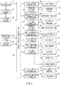
- FIG. 5 is a block diagram illustrating an example of a configuration of the image forming apparatus illustrated in FIG. 2 .
- FIG. 6 is a plan view for describing a configuration of a toner image according to a first configuration example.
- FIG. 7 is another plan view for describing the configuration of the toner image according to the first configuration example.
- FIG. 8 is yet another plan view for describing the configuration of the toner image according to the first configuration example.
- FIG. 9 is a plan view for describing a configuration of the toner image according to a second configuration example.
- FIG. 10 is a plan view for describing a configuration of the toner image according to a third configuration example.
- FIG. 11 is a plan view for describing a configuration of the toner image according to a fourth configuration example.
- FIG. 12 is a plan view for describing a configuration of the toner image according to a fifth configuration example.
- FIG. 13 is a plan view for describing a configuration of the toner image according to a sixth configuration example.
- FIG. 14 is a plan view for describing a configuration of the toner image according to a seventh configuration example.
- FIG. 15 is a plan view for describing an example of one principle of controlling a conveying speed and a cutting speed.
- FIG. 16 is another plan view for describing one example of the principle of controlling the conveying speed and the cutting speed.
- FIG. 17 is yet another plan view for describing the example of one principle of controlling the conveying speed and the cutting speed.
- FIG. 18 is a diagram illustrating an example of detection results obtained by image detection sensors.
- FIG. 19 is a diagram illustrating another example of the detection results obtained by the image detection sensors.
- FIG. 20 is a flowchart illustrating an example of a flow of an adjustment operation of a cutting process.
- FIG. 21 is a schematic plan view of an example of a configuration of an image forming apparatus according to one embodiment of the technology.
- FIG. 22 is a plan view for describing an example of one principle of controlling the conveying speed and the cutting speed.
- FIG. 23 is another plan view for describing one example of the principle of controlling the conveying speed and the cutting speed.
- FIG. 24 is yet another plan view for describing one example of the principle of controlling the conveying speed and the cutting speed.
- FIG. 25 is yet another plan view for describing one example of the principle of controlling the conveying speed and the cutting speed.
- FIG. 26 is a diagram illustrating an example of the detection results obtained by the image detection sensors.
- FIG. 27 is a flowchart illustrating an example of a flow of the adjustment operation of the cutting process.
- FIG. 28 is a schematic plan view of an example of a configuration of an image forming apparatus according to one embodiment of the technology.
- FIG. 29 is a plan view for describing an example of an adjustment procedure in the cutting process.
- FIG. 30 is a flowchart illustrating an example of a flow of the adjustment operation of the cutting process.
- FIG. 31 is a plan view of a configuration of the toner image according to a modification example.
- FIG. 32 is a plan view of a configuration of the toner image according to another modification example.
- FIG. 33 is a plan view of a configuration of the toner image according to yet another modification example.
- FIG. 34 is a plan view of a configuration of the toner image according to yet another modification example.
- the image forming apparatus may form an image on a print medium M with the use of a toner T illustrated in FIG. 3 .
- the print medium M will be described later with reference to FIG. 2 .
- the image forming apparatus may be, for example, a full-color printer based on a so-called electrophotographic method.
- the image forming apparatus cuts the print medium M, and forms an image on a surface of the cut print medium M.
- the print medium M may be a roll of print medium M.
- the print medium M does not necessarily have to be rolled in the form of the roll as long as the print medium M is subjected to a cutting process.
- the print medium M may include one or more of materials such as paper or a film.
- FIG. 1 illustrates an example of a perspective configuration of the image forming apparatus according to the first example embodiment.
- FIG. 2 schematically illustrates an example of a plan configuration of the image forming apparatus illustrated in FIG. 1 .
- FIG. 3 illustrates, in an enlarged fashion, an example of a plan configuration of a developing unit 10 illustrated in FIG. 2 .
- FIG. 4 illustrates, in an enlarged fashion, an example of a configuration of a transfer section 20 illustrated in FIG. 2 , together with image detection sensors 40 .
- the upper side, the lower side, the left side, and the right side of the image forming apparatus illustrated in FIG. 1 are respectively referred to as upper (or the upper side), lower (or the lower side), front (or the front side), and rear (or the rear side).
- the image forming apparatus may include an image forming unit 100 and a medium feeding unit 200 , for example.
- the image forming unit 100 may form an image on the surface of the print medium M fed from the medium feeding unit 200 .
- the image forming unit 100 may have an image forming device 130 provided in a housing 110 .
- the housing 110 may be attached with a top cover 120 .
- the housing 110 may contain the image forming device 130 .
- the housing 110 may be a box-shaped member having an opening at an upper part of the housing 110 as illustrated in FIGS. 1 and 2 .
- the housing 110 may have a discharge opening 110 H at a front face of the housing 110 .
- the discharge opening 110 H may discharge the print medium M on which an image has been formed.
- the top cover 120 may cover the opening of the housing 110 in which the image forming device 130 is disposed.
- the top cover 120 may be a plate-shaped member as illustrated in FIGS. 1 and 2 , and may be openable on an as-needed basis.
- the top cover 120 may have an upper face that is provided with an opening-closing lever 121 , for example.
- the opening-closing lever 121 may serve as a holding member that allows the top cover 120 to be opened or closed.
- the top cover 120 may have a front face that is provided with an operation interface panel 122 , for example.
- the operation interface panel 122 may be operated by a user upon using the image forming apparatus, and will be described later in greater detail.
- the housing 110 may have a through hole 110 K provided at a rear part of the housing 110 .
- the top cover 120 may also have a through hole 120 K provided at a rear part of the top cover 120 .
- the through holes 110 K and 120 K each may extend in a Y-axis direction.
- a shaft 123 may be inserted into the through holes 110 K and 120 K.
- the shaft 123 may be a rod-shaped member, and may extend in the Y-axis direction.
- the top cover 120 may be pivotable around the shaft 123 and may be openable and closable accordingly.
- the image forming device 130 may form an image on the surface of the print medium M with use of the toner T.
- the image forming device 130 may include a developing unit 10 , a transfer section 20 , a fixing section 30 , the image detection sensors 40 , conveying rollers 51 and 52 , and a control board 60 , for example.
- the print medium M to be fed from the medium feeding unit 200 to the image forming unit 100 may be conveyed in a conveyance direction D along a conveyance route P.
- the print medium M may be conveyed in an X-axis direction along the conveyance route P that is denoted by a broken line in FIG. 2 .
- the X-axis direction may correspond to a specific but non-limiting example of a “first direction” in one embodiment of the technology.
- the image detection sensor 40 may correspond to a specific but non-limiting example of a “detector” in one embodiment of the technology.
- the developing unit 10 may perform a developing process, i.e., a process of attaching the toner T to an electrostatic latent image.
- the developing unit 10 may form the electrostatic latent image, and attach the toner T to the electrostatic latent image by utilizing Coulomb force.
- the developing unit 10 when the print medium M is cut by a cutter 204 , forms a toner image G on the surface of the print medium M cut by the cutter 204 and on a surface of a conveyance belt 21 .
- the toner image G may include a medium toner image GA and a conveyance toner image GB.
- the developing unit 10 may form the medium toner image GA on the surface of the print medium M. and form the conveyance toner image GB on the surface of the conveyance belt 21 .
- the medium toner image GA and the conveyance toner image GB each may correspond to a specific but non-limiting example of a “detection image” in one embodiment of the technology.
- the developing unit 10 may cause, by means of a transfer roller 24 , the toner T to be transferred from the surface of the print medium M through a cut edge MT to the surface of the conveyance belt 21 in the conveyance direction D, upon conveyance by the conveyance belt 21 of the print medium M cut by the cutter 204 .
- the developing unit 10 may form the toner image G as illustrated in FIGS. 6 to 14 .
- the thus-formed toner image G may include the medium toner image GA formed on the surface of the print medium M and the conveyance toner image GB formed on the surface of the conveyance belt 21 as described above.
- a configuration of the toner image G, including the medium toner image GA and the conveyance toner image GB, will be described later in greater detail.
- the image forming device 130 may include three developing units 10 , i.e., developing units 10 Y, 10 M, and 10 C.
- the developing units 10 Y, 10 M, and 10 C each may be attached detachably to the housing 110 , and may be disposed in this order from upstream toward downstream along the conveyance route P.
- the developing units 10 Y, 10 M, and 10 C each may include a developing process unit 11 and a toner cartridge 12 , for example.
- the toner cartridge 12 may be attached detachably to the developing process unit 11 , for example.
- the developing process unit 11 may be provided with a light source 13 , for example.
- the developing units 10 Y. 10 M, and 10 C may have configurations same as or similar to each other except for the toners T contained in the respective toner cartridges 12 .
- the toners T may be different in type (e.g., color) from each other.
- the developing process unit 11 may perform the developing process with the use of the toner T fed from the toner cartridge 12 .
- the developing process unit 11 may include a photosensitive drum 112 , a charging roller 113 , a feeding roller 114 , a developing roller 115 , a developing blade 116 , and a cleaning blade 117 that are provided in the housing 111 , for example.
- the housing 111 may have an opening 111 K 1 from which the photosensitive drum 112 is partially exposed, for example.
- the housing 111 may also have an opening 111 K 2 that allows light outputted from the light source 13 to be guided to the photosensitive drum 112 .
- the light source 13 may be disposed outside of the housing 111 , for example.
- the photosensitive drum 112 may be a cylindrical member including an organic photoreceptor that supports the electrostatic latent image.
- the photosensitive drum 112 may extend in the Y-axis direction, and be rotatable around a rotation axis that extends in the Y-axis.
- the charging roller 113 may be so pressed against the photosensitive drum 112 as to be in contact with the photosensitive drum 112 .
- the charging roller 113 may electrically charge a surface of the photosensitive drum 112 .
- the feeding roller 114 may be so pressed against the developing roller 115 as to be in contact with the developing roller 115 .
- the feeding roller 114 may feed the toner T to a surface of the developing roller 115 .
- the developing roller 115 may be so pressed against the photosensitive drum 112 as to be in contact with the photosensitive drum 112 .
- the developing roller 115 may support the toner T that is fed from the feeding roller 114 , and attach the fed toner T onto the electrostatic latent image formed on the surface of the photosensitive drum 112 .
- any component referred to by the name that contains the term “roller”, such as the charging roller 113 described above, may be a cylindrical member that extends in the Y-axis direction and is rotatable around the rotation axis that extends in the Y-axis. The same holds true in the following description for any component referred to by the name that contains the term “roller”.
- the developing blade 116 may be a plate-like member that controls a thickness of the toner T fed to the surface of the developing roller 115 .
- the developing blade 116 may be disposed at a position away from the developing roller 115 with a predetermined distance, i.e., predetermined spacing, in between, for example.
- the thickness of the toner T may be controlled on the basis of the distance, i.e., the spacing, between the developing roller 115 and the developing blade 116 .
- the cleaning blade 117 may be a plate-like elastic member that scrapes off an extraneous material such as unnecessary remains of the toner T that are present on the surface of the photosensitive drum 112 .
- the cleaning blade 117 may extend in a direction substantially parallel to a direction in which the photosensitive drum 112 extends, for example.
- the cleaning blade 117 may be so pressed against the photosensitive drum 112 as to be in contact with the photosensitive drum 112 .
- the toner cartridge 12 may contain the toner T.
- the toner cartridge 12 provided in the developing unit 10 Y may contain a yellow toner, for example.
- the toner cartridge 12 provided in the developing unit 10 M may contain a magenta toner, for example.
- the toner cartridge 12 provided in the developing unit 10 C may contain a cyan toner, for example.
- the light source 13 may be an exposure device that performs exposure on the surface of the photosensitive drum 112 to thereby form the electrostatic latent image on the surface of the photosensitive drum 112 .
- the light source 13 may be, for example, a light-emitting diode (LED) head that has components including an LED element and a lens array.
- the LED element and the lens array may be so disposed that the light outputted from the LED element forms an image on the surface of the photosensitive drum 112 , for example.
- the transfer section 20 may perform a transfer process of the toner T that has been subjected to the developing process by the developing unit 10 .
- the transfer section 20 may transfer, onto the print medium M, the toner T that has been attached to the electrostatic latent image by the developing unit 10 .
- the transfer section 20 may include the conveyance belt 21 , a driving roller 22 , a driven roller 23 , the transfer roller 24 , a cleaning blade 25 , and a collection box 26 , for example.
- FIG. 4 illustrates only the conveyance belt 21 , the driving roller 22 , and the driven roller 23 .
- the developing unit 10 and the transfer roller 24 may correspond to a specific but non-limiting example of a “detection image forming section” in one embodiment of the technology.
- the conveyance belt 21 may correspond to a specific but non-limiting example of a “second conveyor” in one embodiment of the technology.
- the conveyance belt 21 may convey, in the conveyance direction D, the print medium M cut by the later-described cutter 204 .
- the conveyance belt 21 may be an elastic endless belt, for example.
- the conveyance belt 21 may be able to travel in accordance with rotation of the driving roller 22 , while lying on the driving roller 22 and the driven roller 23 in a stretched state, for example.
- the driving roller 22 may be rotatable, for example, by utilizing power of a device such as a motor.
- the driven roller 23 may be rotatable in accordance with the rotation of the driving roller 22 , for example.
- the transfer roller 24 may transfer, onto the print medium M, the toner T attached to the electrostatic latent image.
- the transfer roller 24 may be so pressed against the photosensitive drum 112 as to be in contact with the photosensitive drum 112 with the conveyance belt 21 in between.
- the number of transfer rollers 24 is not particularly limited.
- the number of transfer rollers 24 may correspond to the number of developing units 10 .
- the image forming apparatus may include three transfer rollers 24 including transfer rollers 24 Y, 24 M, and 24 C, corresponding to the three developing units 10 including the developing units 10 Y, 10 M, and 10 C.
- the cleaning blade 25 may be so pressed against the conveyance belt 21 as to be in contact with the conveyance belt 21 .
- the cleaning blade 25 may scrape off an extraneous material such as unnecessary remains of the toner T on the surface of the conveyance belt 21 .
- the collection box 26 may collect the extraneous material scraped by the cleaning blade 25 .
- the fixing section 30 may perform a fixing process of the toner T that has been transferred onto the print medium M by the transfer section 20 .
- the fixing section 30 may apply a pressure onto the print medium M onto which the toner T has been transferred by the transfer section 20 , while heating the print medium M.
- the fixing section 30 may thereby fix the toner T to the print medium M.
- the fixing section 30 may include a heating roller 31 and a pressure applying roller 32 , for example.
- the heating roller 31 may heat the toner T having been transferred onto the print medium M.
- the heating roller 31 may have a heating source such as a heater 80 (see FIG. 5 ) disposed inside the heating roller 31 , for example.
- a temperature measuring device such as a later-described thermistor (see FIG. 5 ) may be so disposed in the vicinity of the heating roller 31 that the heating roller 31 and the temperature measuring device such as the thermistor may be spaced apart from each other, for example.
- the pressure applying roller 32 may be so pressed against the heating roller 31 as to be in contact with the heating roller 31 .
- the pressure applying roller 32 may apply a pressure onto the toner T transferred onto the print medium M.
- the image detection sensors 40 may be disposed away from each other in a width direction that intersects the conveyance direction D.
- the image detection sensors 40 may be disposed in the width direction (e.g., the Y-axis direction) that is substantially orthogonal to the conveyance direction D.
- the Y-axis direction may correspond to a specific but non-limiting example of a “second direction” in one embodiment of the technology.
- the width direction may be orthogonal to the conveyance direction D.
- the image detection sensors 40 may detect the toner image G at two positions that are different from each other in the width direction.
- the image detection sensors 40 may detect the conveyance toner image GB formed on the conveyance belt 21 , out of the above-described toner image G including the medium toner image GA and the conveyance toner image GB.
- the image detection sensors 40 may be disposed below the conveyance belt 21 .
- the image detection sensors 40 each may be disposed at a position that is upstream of a position at which formation of the toner image G starts and that is downstream of a position at which the formation of the toner image G ends, in a traveling direction of the conveyance belt 21 .
- the conveyance belt 21 may be disposed in a region between the developing unit 10 and the image detection sensors 40 , for example.
- the image detection sensors 40 may be disposed away from each other in the width direction as described above. Hence, in an example embodiment, the image detection sensors 40 may detect, on the basis of the conveyance toner image GB, positions of the conveyance toner image GB at two positions that are different from each other in the width direction. In such an example embodiment, the image detection sensors 40 may detect, at the respective two positions, timings at which the detection of the conveyance toner image GB is started. In an alternative example embodiment, the image detection sensors 40 may detect, at the respective two positions, formation sizes of the conveyance toner image GB, on the basis of the conveyance toner image GB.
- the image detection sensors 40 may detect, as a non-limiting example of the formation size, lengths of the conveyance toner image GB in the conveyance direction D.
- the image detection sensors 40 may detect, at the respective two positions, timings at which the detection of the conveyance toner image GB is started and timings at which the detection of the conveyance toner image GB is ended.
- the number of image detection sensors 40 are not particularly limited as long as two or more image detection sensors 40 are provided.
- the number of image detection sensors 40 may be two, i.e., the image detection sensors 40 may include image detection sensors 41 and 42 as illustrated in FIG. 4 .
- the image detection sensors 40 may include image detection sensors 41 and 42 that are disposed away from each other in the width direction.
- the image detection sensor 41 and the image detection sensor 42 may respectively detect a later-described toner image G 1 (e.g., the conveyance toner image GB) and a later-described toner image G 2 (e.g., the conveyance toner image GB) as illustrated by way of example in FIGS. 6 to 14 , for example.
- a distance or an interval between the image detection sensor 41 and the image detection sensor 42 is not particularly limited. However, in an example embodiment, the interval between the image detection sensor 41 and the image detection sensor 42 may be sufficiently large to allow for easier calculation, with high accuracy, of a starting time difference ⁇ TS, an ending time difference ⁇ TE, and a detection time difference ⁇ TC that are described later in greater detail.
- the image detection sensor 41 may correspond to a specific but non-limiting example of a “first detector” in one embodiment of the technology.
- the image detection sensor 42 may correspond to a specific but non-limiting example of a “second detector” in one embodiment of the technology.
- the image detection sensors 40 are each not limited in its kind as long as the image detection sensors 40 are able to detect the toner image G, e.g., the conveyance toner image GB.
- the image detection sensors 40 each may include an optical device that is able to detect presence of the toner image G by means of a reflection phenomenon of light.
- the image detection sensors 40 each may include a photosensor. The photosensor may be able to output an output value that corresponds to a concentration of the toner image G, in order to allow for the detection of the presence of the toner image G that serves as a detection target, for example.
- the conveying roller 51 and the conveying roller 52 may convey the print medium M in the conveyance direction D along the conveyance route P as with the conveyance belt 21 .
- the conveying rollers 51 and 52 each may include a pair of rollers that face each other with the conveyance route P in between.
- the conveyance belt 21 may be disposed between the conveying rollers 51 and 52 , for example.
- the control board 60 may have a central processing unit (CPU), for example.
- the control board 60 may control the image forming apparatus as a whole.
- a configuration of the control board 60 including a block configuration, will be described later in greater detail with reference to FIG. 5 .
- the medium feeding unit 200 may feed the print medium M to the image forming unit 100 .
- the medium feeding unit 200 may cut the rolled print medium M, and may thereafter convey the cut medium M along the conveyance route P, thereby feeding the print medium M, having been subjected to the cutting, from the medium feeding unit 200 to the image forming unit 100 .
- the medium feeding unit 200 may be attached at a rear part of the image forming unit 100 .
- the medium feeding unit 200 in an example embodiment may have a conveying roller 202 , a conveying roller 203 , and the cutter 204 that are disposed in a housing 201 , for example.
- the conveying rollers 202 and 203 and the cutter 204 may be disposed in this order from upstream to downstream of the conveyance route P.
- the conveying rollers 202 and 203 may correspond to a specific but non-limiting example of a “first conveyor” in one embodiment of the technology.
- the cutter 204 may correspond to a specific but non-limiting example of a “cutter” in one embodiment of the technology.
- the conveying roller 202 and the conveying roller 203 may convey the rolled print medium M along the conveyance route P and thereby convey the rolled print medium M to the cutter 204 .
- the conveying rollers 202 and 203 each may include a pair of rollers that face each other with the conveyance route P in between, as with the conveying rollers 51 and 52 .
- the cutter 204 may so cut the rolled print medium M conveyed by the conveying rollers 202 and 203 as to cause the cut print medium M to have a predetermined size, e.g., a predetermined length.
- the cutter 204 may include a rotary cutter.
- the rotary cutter may extend in the Y-axis direction, and may be rotatable around a rotation axis that extends in the Y-axis direction.
- the rotary cutter may be rotatable and cut the print medium M upon the conveyance of the rolled print medium M by the conveying rollers 202 and 203 .
- the cutter 204 may be able to cut the rolled print medium M while conveying the rolled print medium M.
- the print medium M following the cutting by the cutter 204 may thus have the cut edge MT, as described later in greater detail with reference to FIGS. 6 to 14 .
- FIG. 5 illustrates an example of the block configuration of the image forming apparatus illustrated in FIG. 2 , together with some of the components of the image forming apparatus that are already described above.
- the image forming apparatus may have an image forming controller 61 , an interface (I/F) controller 62 , a reception memory 63 , an editing memory 64 , various sensors 65 , a light source controller 66 , a charging voltage controller 67 , a supply voltage controller 68 , a developing voltage controller 69 , a transfer voltage controller 70 , a roller driving controller 71 , a drum driving controller 72 , a belt driving controller 73 , a fixing controller 74 , a sensor driving controller 75 , and a cutter driving controller 76 , for example.
- I/F interface
- the image forming controller 61 may control an operation of the image forming apparatus as a whole.
- the image forming controller 61 may have one or more of electronic components including, but not limited to, a control circuit, a memory, an input/output port, and a timer.
- the control circuit may include a device such as CPU.
- the memory may include one or more of memory devices including, but not limited to, a read-only memory (ROM) and a random-access memory (RAM).
- the image forming controller 61 may correspond to a specific but non-limiting example of a “controller” in one embodiment of the technology.
- the image forming controller 61 varies one or both of a conveying speed of the print medium M to be conveyed by the conveying rollers 202 and 203 and a cutting speed of the print medium M to be cut by the cutter 204 .
- the image forming controller 61 varies one or both of the conveying speed and the cutting speed on the basis of a comparison of the conveyance toner image GB detected, at the two positions that are different from each other in the width direction, by the image detection sensors 40 , e.g., by the image detection sensors 41 and 42 .
- the I/F controller 62 may receive information such as data transmitted from an external apparatus to the image forming apparatus.
- the external apparatus may be any device usable by a user of the image forming apparatus, such as a personal computer.
- the information to be transmitted from the external apparatus to the image forming apparatus may be any data directed to formation of an image, such as image data.
- the reception memory 63 may store information such as data received by the image forming apparatus.
- the data may be the above-described image data.
- the editing memory 64 may store information such as image data having been subjected to an editing process.
- the operation interface panel 122 may serve both as a display and an input device, for example.
- the display may display any information necessary for the user to operate the image forming apparatus.
- the input device may be used by the user to operate the image forming apparatus.
- the operation interface panel 122 may include members including a display panel and an operation button.
- the display panel may be a liquid crystal panel having a touch panel functionality, although a kind of the display panel is not particularly limited.
- the various sensors 65 may include one or more of sensors including, but not limited to, a temperature sensor, a humidity sensor, an image density sensor, a medium position detection sensor, a toner remaining level detection sensor, and a human sensor. It is to be noted that the various sensors 65 do not encompass the image detection sensors 40 .
- the light source controller 66 may control an operation related to the light source 13 , such as an exposure operation of the light source 13 , for example.
- the charging voltage controller 67 may control a voltage, such as a voltage to be applied to the charging roller 113 , for example.
- the supply voltage controller 68 may control a voltage, such as a voltage to be applied to the feeding roller 114 , for example.
- the developing voltage controller 69 may control a voltage, such as a voltage to be applied to the developing roller 115 , for example.
- the transfer voltage controller 70 may control a voltage, such as a voltage to be applied to the transfer roller 24 , for example. For example, these voltages may be set in accordance with instructions issued from the image forming controller 61 .
- the image forming apparatus may include three light source controllers 66 corresponding to the respective three developing units 10 including the developing units 10 Y, 10 M, and 10 C. Note that those three light source controllers 66 are not illustrated in FIG. 5 for simplification purpose.
- the three light source controllers 66 may be the light source controller 66 that controls the light source 13 provided in the developing unit 10 Y, the light source controller 66 that controls the light source 13 provided in the developing unit 10 M, and the light source controller 66 that controls the light source 13 provided in the developing unit 10 C.
- the image forming apparatus may include three charging voltage controllers 67 , three supply voltage controllers 68 , three developing voltage controllers 69 , and three transfer voltage controllers 70 that are provided corresponding to the three developing units 10 , for example.
- the roller driving controller 71 may control an operation related to the rollers.
- the roller driving controller 71 may control, through the use of the roller motors 77 , an operation of rotating a series of rollers including the conveying rollers 51 , 52 , 202 , and 203 , the charging roller 113 , the feeding roller 114 , the developing roller 115 , and the transfer roller 24 .
- the drum driving controller 72 may control an operation related to the photosensitive drum 112 .
- the drum driving controller 72 may control, through the use of a drum motor 78 , an operation of rotating the photosensitive drum 112 .
- the belt driving controller 73 may control an operation related to the conveyance belt 21 .
- the belt driving controller 73 may control, through the use of a belt motor 79 , an operation of causing the conveyance belt 21 to travel.
- the fixing controller 74 may control an operation related to a fixing operation.
- the fixing controller 74 may control an operation of the heater 80 on the basis of a temperature measured by the thermistor 81 , and may also control, through the use of fixing motors 82 , an operation of rotating each of the heating roller 31 and the pressure applying roller 32 .
- the sensor driving controller 75 may control an operation related to the image detection sensors 40 .
- the sensor driving controller 75 may control a detection operation to be performed by the image detection sensors 40 .
- the sensor driving controller 75 may output, to the image forming controller 61 , detection results obtained by the image detection sensors 40 .
- the cutter driving controller 76 may control an operation related to the cutter 204 .
- the cutting driving controller 76 may control, through the use of a cutter motor 83 , a cutting operation to be performed by the cutter 204 .
- the image forming apparatus may include three roller driving controllers 71 and three drum driving controllers 72 that are provided corresponding to the three developing units 10 , for example.
- the three roller driving controllers 71 each may control the operation that involves the use of roller motors 77 .
- the three roller driving controllers 71 may control the respective operations of rotating the rollers including the three transfer rollers 24 , i.e., the transfer rollers 24 Y, 24 M, and 24 C.
- FIGS. 6 to 14 each illustrate an example of a plan configuration of elements including the print medium M and the conveyance belt 21 for describing an example configuration of the toner image G, and each correspond to FIG. 4 .
- FIGS. 6 to 14 each illustrate a state in which the print medium M, having been subjected to the cutting of the rolled print medium M by the cutter 204 , is conveyed by the conveyance belt 21 .
- FIG. 6 illustrates a state in which the print medium M has been cut by the cutter 204 normally and the cut edge MT formed on the print medium M extends in the width direction, accordingly.
- FIGS. 7 to 14 each illustrate a state in which the print medium M has not been cut by the cutter 204 normally, e.g., cut obliquely by the cutter 204 , and the cut edge MT extends obliquely relative to the width direction, accordingly.
- the image forming apparatus may form the toner image G, e.g., the medium toner image GA and the conveyance toner image GB, on the surface of the print medium M and the surface of the conveyance belt 21 upon the conveyance, by the conveyance belt 21 , of the print medium M cut by the cutter 204 , for example.
- the toner image G e.g., the medium toner image GA and the conveyance toner image GB
- the toner image G is not particularly limited in its configuration as long as the toner T is transferred from the surface of the print medium M through the cut edge MT to the surface of the conveyance belt 21 in the conveyance direction D as described above.
- Non-limiting examples of the configuration of the toner image G may include the number of toner images G, a length of the toner image G (e.g., a formation size in the conveyance direction D), and a shape of a pattern of the toner image G.
- the number of toner images G may be two, i.e., may include two toner images G 1 and G 2 , as illustrated in FIGS. 6 to 14 .
- the toner image G may include the toner image G 1 and the toner image G 2 that are disposed away from each other in the width direction.
- the toner image G 1 may include a medium toner image G 1 A and a conveyance toner image G 1 B, for example, whereas the toner image G 2 may include a medium toner image G 2 A and a conveyance toner image G 2 B, for example.
- a length L 1 of the toner image G 1 and a length L 2 of the toner image G 2 may be equal to each other, for example.
- the medium toner image G 1 A may correspond to a specific but non-limiting example of a “first detection image” in one embodiment of the technology.
- the medium toner image G 2 A may correspond to a specific but non-limiting example of a “second detection image” in one embodiment of the technology.
- the conveyance toner image G 1 B may correspond to a specific but non-limiting example of the “first detection image” in one embodiment of the technology.
- the conveyance toner image G 2 B may correspond to a specific but non-limiting example of the “second detection image” in one embodiment of the technology.
- the toner image G may extend continuously from the surface of the print medium M through the cut edge MT to the surface of the conveyance belt 21 in the conveyance direction D. In an alternative example embodiment, the toner image G may extend discontinuously, e.g., intermittently, from the surface of the print medium M through the cut edge MT to the surface of the conveyance belt 21 in the conveyance direction D.
- the toner image G may have any of a series of pattern shapes as illustrated by way of example in FIGS. 6 to 14 as the pattern shape of the toner image G.
- the toner image G 1 and the toner image G 2 may have their respective pattern shapes that are same as each other. Note that, in an alternative example embodiment, two or more of the series of patterns illustrated by way of example in FIGS. 6 to 14 may be combined in any combination.
- FIGS. 6 to 8 each illustrate an example embodiment in which the toner image G has, as the pattern shape, a rectangular solid pattern that extends continuously in the conveyance direction D.
- FIG. 9 illustrates an example embodiment in which the toner image G has, as the pattern shape, a rectangular pattern having dots that extends continuously in the conveyance direction D.
- FIG. 10 illustrates an example embodiment in which the toner image G has, as the pattern shape, a rectangular frame pattern that extends continuously in the conveyance direction D.
- FIG. 11 illustrates an example embodiment in which the toner image G has, as the pattern shape, a rectangular ruled pattern that extends continuously in the conveyance direction D.
- the toner image G has, as the pattern shape, a rectangular scaled pattern that extends continuously in the conveyance direction D.
- the toner image G in the example embodiment illustrated in FIG. 12 may have a plurality of frame-shaped scales S that are so arrayed as to be adjacent to each other in the conveyance direction D.
- FIGS. 13 and 14 each illustrate an example embodiment in which the toner image G has, as the pattern shape, a rectangular solid pattern that extends intermittently in the conveyance direction D.
- the toner images G in the respective example embodiments illustrated in FIGS. 13 and 14 each may have a plurality of boxes B that are so arrayed as to be separated away from each other in the conveyance direction D.
- a distance or an interval between the two mutually-adjacent boxes B may be fixed in the plurality of boxes B, whereas, in the example embodiment illustrated in FIG. 14 , the distance or the interval between the two mutually-adjacent boxes B may be varied in the plurality of boxes B.
- the intervals positioned upstream and downstream in the conveyance direction D may be made relatively larger, and the plurality of intervals positioned in the middle between the relatively larger intervals may be made smaller.
- the number of image detection sensors 40 is two, i.e., the image detection sensors 40 include the image detection sensors 41 and 42 ;
- the number of toner images G is two, i.e., the toner images G include the toner images G 1 and G 2 ;
- the toner image G has the continuous solid pattern as its configuration as illustrated in FIGS. 6 to 8 ;
- the cutter 204 includes the rotatable rotary cutter.
- FIGS. 15 to 17 illustrate plan configurations corresponding to the respective configurations illustrated in FIGS. 6 to 8 for describing one example of the principle of controlling the conveying speed and the cutting speed. Note that FIGS. 15 to 17 each illustrate a state in which the print medium M has been conveyed more in the conveyance direction D than that in the example case illustrated in each of FIGS. 6 to 8 , and each illustrate the fixing section 30 including the heating roller 31 and the pressure applying roller 32 as well.
- FIGS. 18 and 19 each illustrate an example of detection results obtained by the image detection sensors 41 and 42 .
- FIG. 18 illustrates the detection result corresponding to the example case illustrated in FIG. 15
- FIG. 19 illustrates the detection result corresponding to the example case illustrated in FIG. 16 .
- FIGS. 18 and 19 each also illustrate a detection result D 1 obtained by the image detection sensor 41 , a detection result D 2 obtained by the image detection sensor 42 , a base value BL, and a detection threshold TL.
- the base value BL is a value of a detection level obtained where the image detection sensor 41 or 42 does not detect the corresponding conveyance toner image G 1 B or G 2 B.
- the detection threshold TL is a value of the detection level (i.e., a threshold) serving as a reference used for discriminating between presence and absence of the detection of the conveyance toner image G 1 B or G 2 B.
- the image forming controller 61 may vary one or both of the conveying speed and the cutting speed on the basis of the detection results related to the conveyance toner images G 1 B and G 2 B obtained by the image detection sensors 41 and 42 , for example.
- the rolled print medium M may be cut by the cutter 204 in the medium feeding unit 200 as illustrated in FIG. 2 , following which the print medium M thus having the cut edge MT may be fed to the image forming unit 100 as illustrated in FIGS. 6 to 8 .
- the rolled print medium M may be cut by the cutter 204 upon the conveyance by the conveying rollers 202 and 203 . Accordingly, a cut state of the print medium M by the cutter 204 may possibly vary depending on a relationship between the conveyance speed of the print medium M to be conveyed by the conveying rollers 202 and 203 and the cutting speed of the print medium M to be cut by the cutter 204 , meaning that an extending direction of the cut edge MT may possibly vary as well.
- the cutting speed may correspond to a rotation speed of the cutter 204 , e.g., the rotation speed of the rotary cutter.
- the relationship between the conveying speed and the cutting speed may be appropriate in a case where the conveying speed and the cutting speed are substantially coincident with each other.
- the print medium M may be cut in such a manner that the extending direction of the cut edge MT follows along the width direction as illustrated by way of example in FIG. 6 and the print medium M may be thus cut normally.
- the print medium M may be cut in such a manner that the extending direction of the cut edge MT becomes oblique relative to the width direction as illustrated by way of example in FIGS. 7 and 8 and the print medium M may be thus not cut normally.
- Such improper cutting of the print medium M not only affects a quality of external appearance (e.g., presentation) of the print medium M but also possibly affects a formation accuracy of an image, such as an accuracy of transferring the toner T onto the print medium M. Accordingly, the print medium M not having been cut normally is undesirable in terms of stably forming an image on a surface of the print medium M.
- the print medium M may be further conveyed in the conveyance direction D by the conveyance belt 21 .
- the print medium M having been formed with the medium toner images G 1 A and G 2 A, may be separated from the conveyance belt 21 having been formed with the conveyance toner images G 1 B and G 2 B, following which the print medium M may be further conveyed in the conveyance direction D to thereby enter the fixing section 30 , i.e., enter the heating roller 31 and the pressure applying roller 32 , as illustrated in FIGS. 15 to 17 .
- the conveyance belt 21 having been formed with the conveyance toner images G 1 B and G 2 B may be caused to travel further after the print medium M, having been formed with the medium toner images G 1 A and G 2 A, are separated from the conveyance belt 21 .
- the conveyance toner images G 1 B and G 2 B may pass through regions detectable by the respective image detection sensors 41 and 42 , allowing the image detection sensors 41 and 42 to respectively detect the conveyance toner images G 1 B and G 2 B.
- the image forming controller 61 may be based on one of the following two non-limiting control principles to vary one or both of the conveying speed and the cutting speed on the basis of the detection results obtained by the respective image detection sensors 41 and 42 .
- the image detection sensors 41 and 42 may detect, at the respective two positions, the timings at which the detections of the respective conveyance toner images G 1 B and G 2 B are started.
- the image detection sensors 41 and 42 may output results of the respective detections to the image forming controller 61 .
- the image forming controller 61 may compare the positions of the respective conveyance toner images G 1 B and G 2 B at the two positions. In other words, the image forming controller 61 may compare the timings at which the detections of the respective conveyance toner images G 1 B and G 2 B are started. Through performing the comparison, the image forming controller 61 may calculate a difference between the positions (e.g., the timings) of the respective conveyance toner images G 1 B and G 2 B. In other words, the image forming controller 61 may calculate a difference between the timing at which the detection of the conveyance toner image G 1 B is started and the timing at which the detection of the conveyance toner image G 2 B is started. Through performing the above example process, the image forming controller 61 may determine whether the extending direction of the cut edge MT is oblique relative to the width direction.
- the image detection sensor 41 may detect a time at which the detection of the conveyance toner image G 1 B is started (i.e., a detection starting time T 1 S), and the image detection sensor 42 may detect a time at which the detection of the conveyance toner image G 2 B is started (i.e., a detection starting time T 2 S).
- the starting time difference ⁇ TS may serve as an index that indicates the mismatch (e.g., a difference in speed) between the conveying speed and the cutting speed.
- the starting time difference ⁇ TS may be 0 (zero) as illustrated in FIG. 18 in a case where the print medium M is cut in such a manner that the extending direction of the cut edge MT follows along the width direction as illustrated by way of example in FIG. 15 .
- the starting time difference ⁇ TS may take a value other than 0 in a case where the print medium M is cut in such a manner that the extending direction of the cut edge MT becomes oblique relative to the width direction as illustrated by way of example in FIGS. 16 and 17 .
- the starting time difference ⁇ TS may take a negative value in each of the example cases illustrated in FIGS. 16 and 19
- the starting time difference ⁇ TS may take a positive value in the example case illustrated in FIG.
- the image forming controller 61 may be able to determine whether the print medium M is cut in such a manner that the extending direction of the cut edge MT becomes oblique relative to the width direction on the basis of the value of the starting time difference ⁇ TS, e.g., on the basis of whether the value of the starting time difference ⁇ TS is 0.
- the image forming controller 61 may determine that the print medium M is cut normally in the example case where the starting time difference ⁇ TS is 0, because in this case the print medium M is cut in such a manner that the extending direction of the cut edge MT follows along the width direction. Accordingly, the image forming controller 61 does not vary one or both of the conveying speed and the cutting speed.
- the image forming controller 61 may determine that the print medium M is not cut normally in the example case where the starting time difference ⁇ TS takes the value other than 0 (e.g., the starting time difference ⁇ TS takes the negative value or the positive value), because in this case the print medium M is cut in such a manner that the extending direction of the cut edge MT becomes oblique relative to the width direction. Accordingly, the image forming controller 61 may vary one or both of the conveying speed and the cutting speed.
- the image forming controller 61 may so vary one or both of the conveying speed and the cutting speed as to cause the value of the starting time difference ⁇ TS to be closer to 0.
- the image forming controller 61 may vary the conveying speed through causing the roller driving controller 71 to vary a rotation speed of the roller motor 77 .
- the image forming controller 61 may vary the cutting speed through causing the cutter driving controller 76 to vary a rotation speed of the cutter motor 83 . e.g., through varying the rotation speed of the rotary cutter.
- the image forming controller 61 may so adjust the cutting process of the print medium M as to cause the extending direction of the cut edge MT to follow along the width direction.
- the image forming controller 61 may increase the conveying speed because the conveying speed is relatively smaller than the cutting speed, or may decrease the cutting speed because the cutting speed is relatively larger than the conveying speed.
- the image forming controller 61 may decrease the conveying speed because the conveying speed is relatively larger than the cutting speed, or may increase the cutting speed because the cutting speed is relatively smaller than the conveying speed.
- a level of decreasing the starting time difference ⁇ TS is not particularly limited.
- a value of the starting time difference ⁇ TS after controlling one or both of the conveying speed and the cutting speed may be 0 or any value other than 0, as long as the starting time difference ⁇ TS after the control takes a value that is closer to 0 than an initial value of the starting time difference ⁇ TS, i.e., than the value of the starting time difference ⁇ TS that is prior to the control of one or both of the conveying speed and the cutting speed.
- the image detection sensors 41 and 42 may detect, at the respective two positions that are different from each other in the width direction, the lengths of the respective conveyance toner images G 1 B and G 2 B on the basis of the conveyance toner images G 1 B and G 2 B.
- the image detection sensors 41 and 42 may output results of the respective detections to the image forming controller 61 .
- the image forming controller 61 may compare the lengths of the respective conveyance toner images G 1 B and G 2 B at the two positions.
- the image forming controller 61 may calculate a difference between the lengths of the respective conveyance toner images G 1 B and G 2 B. In other words, the image forming controller 61 may calculate a difference between the length of the conveyance toner image G 1 B and the length of the conveyance toner image G 2 B. Through performing the above example process, the image forming controller 61 may determine whether the extending direction of the cut edge MT is oblique relative to the width direction.
- the image detection sensor 41 may detect the time at which the detection of the conveyance toner image G 1 B is started (i.e., the detection starting time T 1 S) and a time at which the detection of the conveyance toner image G 1 B is ended (i.e., a detection ending time T 1 E).
- the image detection sensor 42 may detect the time at which the detection of the conveyance toner image G 2 B is started (i.e., the detection starting time T 2 S) and a time at which the detection of the conveyance toner image G 2 B is ended (i.e., a detection ending time T 2 E).
- the image forming controller 61 may calculate a detection time T 1 C and a detection time T 2 C.
- the detection time difference ⁇ TC may serve as another index that indicates the mismatch (e.g., a difference in speed) between the conveying speed and the cutting speed.
- the detection time difference ⁇ TC may be 0 (zero) as illustrated in FIG. 18 in a case where the print medium M is cut in such a manner that the extending direction of the cut edge MT follows along the width direction as illustrated by way of example in FIG. 15 .
- the detection time difference ⁇ TC may take a value other than 0 in a case where the print medium M is cut in such a manner that the extending direction of the cut edge MT becomes oblique relative to the width direction as illustrated by way of example in FIGS. 16 and 17 .
- the detection time difference ⁇ TC may take a negative value in each of the example cases illustrated in FIGS. 16 and 19
- the detection time difference ⁇ TC may take a positive value in the example case illustrated in FIG.
- the image forming controller 61 may be able to determine whether the print medium M is cut in such a manner that the extending direction of the cut edge MT becomes oblique relative to the width direction on the basis of the value of the detection time difference ⁇ TC, e.g., on the basis of whether the value of the detection time difference ⁇ TC is 0.
- the image forming controller 61 may determine that the print medium M is cut normally in the example case where the detection time difference ⁇ TC is 0 and does not vary one or both of the conveying speed and the cutting speed accordingly, as with the example case where the starting time difference ⁇ TS is 0.
- the image forming controller 61 may determine that the print medium M is not cut normally in the example case where the detection time difference ⁇ TC take the value other than 0 (e.g., the detection time difference ⁇ TC take the negative value or the positive value) and may vary one or both of the conveying speed and the cutting speed accordingly, as with the example case where the starting time difference ⁇ TS takes the value other than 0.
- a method of controlling one or both of the conveying speed and the cutting speed to be performed here is as described in detail above. It is to be also noted that a level of decreasing the detection time difference ⁇ TC may be the same or similar to what has been described in detail above with respect to the level of decreasing the starting time difference ⁇ TS.
- the image forming controller 61 may select to vary the conveying speed instead of selecting to vary the cutting speed in each of the first and the second control principles.
- the cutter 204 may be directly coupled to the cutter motor 83 and hence the cutting speed, determined in accordance with a rotation operation of the cutter motor 83 , is less susceptible to a change in kind of the print medium M, in an environmental condition, or in any other factor.
- the conveying rollers 202 and 203 come into contact with the print medium M upon the conveyance and hence the conveying speed, determined in accordance with a rotation operation of each of the conveying rollers 202 and 203 , is more susceptible to the change in kind of the print medium M, in the environmental condition, or in any other factor.
- the image forming controller 61 may vary the conveying speed while setting the cutting speed to be constant.
- the image forming apparatus may perform a developing process, a transfer process, and a fixing process in this order as will be described below, for example. Further, the image forming apparatus may perform a cleaning process on an as-needed basis. For example, such a series of processes may be controlled by the control board 60 , e.g., by the image forming controller 61 .
- the medium feeding unit 200 may cut the rolled print medium M by the cutter 204 while conveying the rolled print medium M by the conveying rollers 202 and 203 . Thereafter, the medium feeding unit 200 may feed the print medium M cut by the cutter 204 to the image forming unit 100 .
- the charging roller 113 may apply a direct-current voltage to the surface of the photosensitive drum 112 while rotating in accordance with the rotation of the photosensitive drum 112 .
- the surface of the photosensitive drum 112 may be thereby electrically charged evenly.
- the light source 13 may apply light to the surface of the photosensitive drum 112 on the basis of image data.
- a surface potential in a region, of the surface of the photosensitive drum 112 , on which the light is applied is thereby attenuated. In other words, optical attenuation occurs.
- An electrostatic latent image may be thus formed on the surface of the photosensitive drum 112 .
- the image data described above may be supplied to the image forming apparatus from the external apparatus such as a personal computer, for example.
- the feeding roller 114 and the developing roller 115 may rotate when receiving application of the voltage.
- the toner T may be thereby fed from the feeding roller 114 to the developing roller 115 . Further, the toner T may move from the developing roller 115 to the photosensitive drum 112 upon the rotation of the photosensitive drum 112 .
- the toner T may be thereby attached to the photosensitive drum 112 , i.e., to the electrostatic latent image.
- the toner T attached to the developing roller 115 may be partially removed by the developing blade 116 , whereby the toner T attached to the developing roller 115 may be caused to have an even thickness.
- the toner T may be stirred in the developing unit 10 (e.g., in the toner cartridge 12 ) to thereby feed the toner T from the toner cartridge 12 to the developing process unit 11 .
- the driven roller 23 may rotate in accordance with the rotation of the driving roller 22 . This may cause the conveyance belt 21 to travel.
- the transfer roller 24 may be so pressed against the photosensitive drum 112 as to be in contact with the photosensitive drum 112 with the conveyance belt 21 in between.
- the toner T that has been attached to the photosensitive drum 112 in the foregoing developing process may be transferred onto the print medium M upon application of the voltage to the transfer roller 24 .
- the print medium M may be so conveyed as to pass through a region between the heating roller 31 and the pressure applying roller 32 in the fixing section 30 .
- the toner T that has been transferred onto the print medium M may be thereby heated, which may cause the toner T to melt.
- the molten toner T may be so pressed against the print medium M while being applied with a pressure. This may cause the toner T to be so attached to the print medium M as to be in close contact with the print medium M.
- the toner T may be fixed to the print medium M, resulting in formation of an image on the print medium M.
- the print medium M thus formed with the image may be discharged from the discharge opening 110 H.
- the kind of toner T and the number of toners T to be used for formation of an image may be determined on the basis of a combination of colors necessary for the formation of such an image.
- the photosensitive drum 112 may rotate while being so pressed against the cleaning blade 117 as to be in contact with the cleaning blade 117 . This may cause an extraneous material such as the unnecessary remains of the toner T present on the surface of the photosensitive drum 112 to be scraped off by the cleaning blade 117 . As a result, the extraneous material may be removed from the surface of the photosensitive drum 112 .
- the cleaning blade 25 may scrape off an extraneous material such as the unnecessary remains of the toner T present on the surface of the conveyance belt 21 upon traveling of the conveyance belt 21 .
- unnecessary remains of the toner T may be removed from the surface of the conveyance belt 21 and may be collected by the collection box 26 .
- the image forming apparatus i.e., the image forming controller 61 , may perform the adjustment operation of the cutting process at any timing as described below, on the basis of any of the foregoing first and second principles of controlling the conveying speed and the cutting speed.
- the timing at which the adjustment operation of the cutting process is performed may be made settable on an as-necessary basis, as long as the timing is other than a timing at which the formation of the print medium M is carried out in accordance with the use of the image forming apparatus by the user, i.e., other than a timing upon the regular use of the image forming apparatus.
- the timing at which the adjustment operation of the cutting process is performed may be a timing at which a predetermined time is elapsed from the initial use of the image forming apparatus, or may be a timing at which the predetermined number of image formation times is performed from the initial use of the image forming apparatus.
- FIG. 20 illustrates an example of a flow of the adjustment operation of the cutting process for describing the example adjustment operation of the cutting process. Note that step numbers in parentheses described below correspond to those illustrated in FIG. 20 .
- the image forming controller 61 may first cause the roller driving controller 71 (i.e., may first use the roller motors 77 ) to rotate the conveying rollers 202 and 203 to thereby convey the rolled print medium M in the conveyance direction D along the conveyance route P at any timing described above (step S 11 ).
- the roller driving controller 71 i.e., may first use the roller motors 77
- the roller driving controller 71 may first use the roller motors 77 to rotate the conveying rollers 202 and 203 to thereby convey the rolled print medium M in the conveyance direction D along the conveyance route P at any timing described above.
- the rolled print medium M may be fed to the cutter 204 .
- the image forming controller 61 may cause the cutter driving controller 76 (i.e., may use the cutter motor 83 ) to operate the cutter 204 and may thereby cut the rolled print medium M (step S 12 ).
- the rotary cutter may cut the rolled print medium M upon its rotation.
- the print medium M thus cut by the cutter 204 may be continuously conveyed in the conveyance direction D along the conveyance route P by the conveying rollers 202 and 203 so as to be fed from the medium feeding unit 200 to the image forming unit 100 .
- the print medium M may be further conveyed in the conveyance direction D along the conveyance route P by the conveyance belt 21 and the conveying rollers 51 and 52 .
- the image forming controller 61 may cause, upon conveying the print medium M in the conveyance direction D, the toner T to be transferred onto the surface of the print medium M and the surface of the conveyance belt 21 through the use of the developing unit 10 and the transfer roller 24 , and may thereby form the toner images G 1 and G 2 , i.e., may thereby form the medium toner image GA and the conveyance toner image GB (step S 13 ).
- the print medium M having been formed with the toner images G 1 and G 2 may be further conveyed in the conveyance direction D so that the conveyance belt 21 having been formed with the conveyance toner images G 1 B and G 2 B is separated from the print medium M having been formed with the medium toner images G 1 A and G 2 A.
- the print medium M having been formed with the medium toner images G 1 A and G 2 A may enter the fixing section 30 , whereas the conveyance belt 21 having been formed with the conveyance toner images G 1 B and G 2 B may be caused to further travel in accordance with the rotation of each of the driving roller 22 and the driven roller 23 .
- the image forming controller 61 may cause the sensor driving controller 75 to operate the image detection sensors 41 and 42 and thereby detect the conveyance toner images G 1 B and G 2 B formed on the surface of the conveyance belt 21 (step S 14 ).
- the detection results obtained by the respective image detection sensors 41 and 42 may include the detection starting times T 1 S and T 2 S and the detection ending times T 1 E and T 2 E as described above, and may be supplied to the image forming controller 61 .
- the image forming controller 61 may calculate the starting time difference ⁇ TS on the basis of the detection results obtained by the respective image detection sensors 41 and 42 , e.g., on the basis of the comparison between the conveyance toner images G 1 B and G 2 B respectively detected by the image detection sensors 41 and 42 at the two positions that are different from each other in the width direction (step S 15 ).
- a non-limiting example of a procedure for calculating the starting time difference ⁇ TS is as described above.
- the image forming controller 61 may determine, on the basis of a result of the calculation of the starting time difference ⁇ TS, whether the starting time difference ⁇ TS takes a value other than 0 (step S 16 ).
- the image forming controller 61 may determine that the print medium M has been cut normally, because the print medium M has been cut in such a manner that the extending direction of the cut edge MT follows along the width direction. In this case, the image forming controller 61 may end the adjustment operation of the cutting process, because it is not necessary to perform the adjustment operation of the cutting process.
- the image forming controller 61 may determine that the print medium M has not been cut normally, because the print medium M has been cut in such a manner that the extending direction of the cut edge MT becomes oblique relative to the width direction. In this case, the image forming controller 61 may perform the adjustment operation of the cutting process, because it is necessary to perform the adjustment operation of the cutting process. For example, the image forming controller 61 may so vary the conveying speed through the use of the roller driving controller 71 , i.e., the roller motors 77 , as to cause the value of the starting time difference ⁇ TS to be closer to 0 (step S 17 ).
- a non-limiting example of a procedure for varying the conveying speed is as described above.
- the conveying speed may be made appropriate with respect to the cutting speed, allowing the print medium M to be cut in such a manner that the extending direction of the cut edge MT follows along the width direction when the rolled print medium M is to be cut by the cutter 204 next time and after, and thereby completing the adjustment operation of the cutting process.
- the toner T having been transferred onto the surface of the conveyance belt 21 for the formation of the conveyance toner image GB may be scraped off by the cleaning blade 25 as a result of further traveling of the conveyance belt 21 .
- the toner T may be removed from the surface of the conveyance belt 21 and may be collected by the collection box 26 .
- the image forming controller 61 may calculate the detection time difference ⁇ TC on the basis of the detection results obtained by the respective image detection sensors 41 and 42 (step S 15 ) instead of calculating the starting time difference ⁇ TS. Through calculating the detection time difference ⁇ TC instead of the starting time difference ⁇ TS, the image forming controller 61 may determine whether the detection time difference ⁇ TC takes a value other than 0 (step S 16 ).
- a non-limiting example of a procedure for calculating the detection time difference ⁇ TC is as described above.
- the image forming controller 61 may end the adjustment operation of the cutting process in a case where the detection time difference ⁇ TC is 0 (step S 16 ; N), and may so vary the conveying speed as to cause the value of the detection time difference ⁇ TC to be closer to 0 (step S 17 ) in a case where the detection time difference ⁇ TC takes the value other than 0 (step S 16 : Y).
- the image forming controller 61 may use both of the starting time difference ⁇ TS and the detection time difference ⁇ TC upon performing the adjustment operation of the cutting process.
- the image forming controller 61 may vary the cutting speed (step S 17 ) instead of varying the conveying speed upon performing the adjustment operation of the cutting process.
- a non-limiting example of a procedure for varying the cutting speed is as described above.
- the image forming controller 61 may vary both of the conveying speed and the cutting speed upon performing the adjustment operation of the cutting process.
- the conveying rollers 202 and 203 conveys the print medium M, and the cutter 204 cuts the print medium M. Further, the developing unit 10 and the transfer roller 24 form the toner image G, e.g., the medium toner image GA and the conveyance toner image GB, on the print medium M and the conveyance belt 21 . Thereafter, the image detection sensors 40 detects, at the two positions, the conveyance toner image GB, and the image forming controller 61 varies one or both of the conveying speed and the cutting speed on the basis of the comparison of the conveyance toner image GB detected at the two positions by the image detection sensors 40 .
- the image detection sensors 40 detects, at the two positions, the conveyance toner image GB
- the image forming controller 61 varies one or both of the conveying speed and the cutting speed on the basis of the comparison of the conveyance toner image GB detected at the two positions by the image detection sensors 40 .
- a determination may be made, on the basis of the detection results obtained by the image detection sensors 40 , as to whether the print medium M is cut in such a manner that the extending direction of the cut edge MT becomes oblique relative to the width direction.
- one or both of the conveying speed and the cutting speed may be varied to thereby adjust the cutting process of the print medium M such that the extending direction of the cut edge MT follows along the width direction.
- This configuration makes it easier to cut the print medium M by the cutter 204 in such a manner that the extending direction of the cut edge MT follows along the width direction and thereby makes it easier to cut the print medium M normally. Hence, it is possible to stably forms an image on the print medium M.
- the image detection sensors 40 may detect, at the two positions, the position of the conveyance toner image GB, and the image forming controller 61 may vary one or both of the conveying speed and the cutting speed on the basis of the comparison between the positions of the conveyance toner image GB detected at the two positions.
- the image detection sensors 40 may detect, at the two positions, the position of the conveyance toner image GB
- the image forming controller 61 may vary one or both of the conveying speed and the cutting speed on the basis of the comparison between the positions of the conveyance toner image GB detected at the two positions.
- the image detection sensors 40 may detect the detection starting time (e.g., the detection starting time T 1 S and the detection starting time T 2 S) at the two positions on the basis of the conveyance toner image GB, and the image forming controller 61 may calculate the starting time difference ⁇ TS and may so vary one or both of the conveying speed and the cutting speed as to cause the value of the starting time difference ⁇ TS to be closer to 0.
- This configuration makes it easier to cut, stably and with high accuracy, the print medium M in such a manner that the extending direction of the cut edge MT follows along the width direction, and thereby makes it easier to adjust the cutting process of the print medium M. Hence, it is possible to achieve higher effects.
- the image detection sensors 40 may detect, at the two positions, the lengths of the conveyance toner image GB, and the image forming controller 61 may vary one or both of the conveying speed and the cutting speed on the basis of the comparison between the lengths of the conveyance toner image GB detected at the two positions.
- the image detection sensors 40 may detect, at the two positions, the lengths of the conveyance toner image GB
- the image forming controller 61 may vary one or both of the conveying speed and the cutting speed on the basis of the comparison between the lengths of the conveyance toner image GB detected at the two positions.
- the image detection sensors 40 may detect the detection starting time (e.g., the detection starting time T 1 S and the detection starting time T 2 S) at the two positions and the detection ending time (e.g., the detection ending time T 1 E and the detection ending time T 2 E) at the two positions on the basis of the conveyance toner image GB, and the image forming controller 61 may calculate the detection time difference ⁇ TC and may so vary one or both of the conveying speed and the cutting speed as to cause the value of the detection time difference ⁇ TC to be closer to 0.
- the detection starting time e.g., the detection starting time T 1 S and the detection starting time T 2 S
- the detection ending time e.g., the detection ending time T 1 E and the detection ending time T 2 E
- This configuration makes it easier to cut, stably and with high accuracy, the print medium M in such a manner that the extending direction of the cut edge MT follows along the width direction, and thereby makes it easier to adjust the cutting process of the print medium M. Hence, it is possible to achieve higher effects.
- the image forming controller 61 may vary the conveying speed. This configuration readily improves an accuracy of varying the speed and thereby makes it easier to adjust the cutting operation of the print medium M such that the extending direction of the cut edge MT follows along the width direction. Hence, it is possible to achieve higher effects.
- the cutter 204 may include the rotary cutter that is rotatable and cut the print medium M upon the conveyance of the print medium M, and the image forming controller 61 may vary the cutting speed on the basis of the rotation speed of the rotary cutter. This configuration makes it easier to vary the cutting speed in accordance with the rotation speed of the rotary cutter. Hence, it is possible to achieve higher effects.
- the developing unit 10 and the transfer roller 24 may form the two toner images G (e.g., the toner images G 1 and G 2 ) that are disposed away from each other in the width direction, and the two image detection sensors 40 (the image detection sensors 41 and 42 ) disposed away from each other in the width direction may be used to detect the respective toner images G 1 and G 2 .
- This configuration makes it easier to cut, on the basis of the starting time difference ⁇ TS or the detection time difference ⁇ TC, the print medium M in such a manner that the extending direction of the cut edge MT follows along the width direction, and thereby makes it easier to adjust the cutting process of the print medium M. Hence, it is possible to achieve higher effects.
- the toner image G may extend, in the conveyance direction D, continuously from the surface of the print medium M through the cut edge MT to the surface of the conveyance belt 21 .
- This configuration makes it easier to calculate the starting time difference ⁇ TS or the detection time difference ⁇ TC on the basis of the toner image G that extends continuously and thereby to cut the print medium M in such a manner that the extending direction of the cut edge MT follows along the width direction, which in turn makes it easier to adjust the cutting process of the print medium M.
- the example workings and the example effects described above are obtainable as well in any embodiment where the toner image G extends intermittently from the surface of the print medium M through the cut edge MT to the surface of the conveyance belt 21 in the conveyance direction D.
- FIG. 21 illustrates an example of a perspective configuration of the image forming apparatus according to the second example embodiment, and corresponds to FIG. 1 .
- FIGS. 22 to 25 illustrate examples of plan configurations corresponding to those illustrated in FIGS. 7, 8, 16, and 17 for describing one example of the principle of controlling the conveying speed and the cutting speed.
- FIG. 26 illustrates an example of detection results obtained by the image detection sensors 41 and 42 , and corresponds to FIG. 19 .
- the image forming apparatus according to the second example embodiment may have a configuration similar to the configuration of the image forming apparatus according to the first example embodiment, with the exception that targets to be detected by the image detection sensors 40 (the image detection sensors 41 and 42 ) are different from the targets to be detected in the first example embodiment and hence locations at which the image detection sensors 40 are disposed are different from the locations in the first example embodiment.
- the image detection sensors 41 and 42 may detect the medium toner image GA (e.g., the medium toner images G 1 A and G 2 A) formed on the surface of the print medium M instead of detecting the conveyance toner image GB (e.g., the conveyance toner images G 1 B and G 2 B) formed on the surface of the conveyance belt 21 .
- the image detection sensors 41 and 42 may be disposed above the conveyance route P in a region between the conveyance belt 21 and the fixing section 30 , for example.
- the image forming apparatus may be based on any of the first and the second control principles in order to vary one or both of the conveying speed and the cutting speed.
- the first and the second control principles may be similar to those of the first example embodiment, with the exception that the image detection sensors 41 and 42 detect the medium toner image GA (e.g., the medium toner images G 1 A and G 2 A) instead of the conveyance toner image GB (e.g., the conveyance toner images G 1 B and G 2 B) as illustrated in FIGS. 22 to 25 .
- the first and the second control principles may also differ from those of the first example embodiment in that the image forming controller 61 calculates, instead of the starting time difference ⁇ TS, the ending time difference ⁇ TE on the basis of the detection ending time T 1 E and the detection ending time T 2 E.
- the image forming controller 61 may vary one or both of the conveying speed and the cutting speed on the basis of the detection results related to the medium toner images G 1 A and G 2 A obtained by the image detection sensors 41 and 42 .
- the image forming controller 61 may calculate the ending time difference ⁇ TE instead of the starting time difference ⁇ TS as described above.
- the image detection sensors 41 and 42 may respectively detect the detection ending time T 1 E and the detection ending time T 2 E, in order to detect, at the two positions that are different from each other in the width direction, the positions of the respective medium toner images G 1 A and G 2 A as illustrated by way of example in FIG. 26 .
- the image forming controller 61 may compare the positions of the respective medium toner images G 1 A and G 2 A at the two positions. In other words, the image forming controller 61 may compare the detection ending time T 1 E and the detection ending time T 2 E.
- the image forming controller 61 may calculate a difference between the positions of the medium toner images G 1 A and G 2 A at the two positions.
- the ending time difference ⁇ TE may be 0 (zero) in a case where the print medium M is cut in such a manner that the extending direction of the cut edge MT follows along the width direction.
- the ending time difference ⁇ TE may take a value other than 0 in a case where the print medium M is cut in such a manner that the extending direction of the cut edge MT becomes oblique relative to the width direction as illustrated by way of example in FIGS. 24 to 26 .
- the image forming controller 61 may be able to determine whether the print medium M is cut in such a manner that the extending direction of the cut edge MT becomes oblique relative to the width direction on the basis of the value of the ending time difference ⁇ TE, e.g., on the basis of whether the value of the ending time difference ⁇ TE is 0.
- the image forming controller 61 may determine that the print medium M is cut normally in the example case where the ending time difference ⁇ TE is 0, because in this case the print medium M is cut in such a manner that the extending direction of the cut edge MT follows along the width direction. Accordingly, the image forming controller 61 does not vary one or both of the conveying speed and the cutting speed.
- the image forming controller 61 may determine that the print medium M is cut obliquely in the example case where the ending time difference ⁇ TE takes the value other than 0 (e.g., the ending time difference ⁇ TE takes the negative value or the positive value), because in this case the print medium M is cut in such a manner that the extending direction of the cut edge MT becomes oblique relative to the width direction. Accordingly, the image forming controller 61 may vary one or both of the conveying speed and the cutting speed.
- the image forming controller 61 may so vary one or both of the conveying speed and the cutting speed as to cause the value of the ending time difference ⁇ TE to be closer to 0.
- a method of controlling one or both of the conveying speed and the cutting speed to be performed here is as described in detail in the first example embodiment.
- a level of decreasing the ending time difference ⁇ TE may be the same or similar to what has been described in detail in the first example embodiment with respect to the level of decreasing the starting time difference ⁇ TS.
- the image detection sensors 41 and 42 may respectively detect the detection starting times T 1 S and T 2 S as well as the detection ending times T 1 E and T 2 E on the basis of the medium toner images G 1 A and G 2 A, instead of detecting the detection starting times T 1 S and T 2 S and the detection ending times T 1 E and T 2 E on the basis of the conveyance toner images G 1 B and G 2 B.
- the image forming controller 61 may calculate the detection time difference ⁇ TC on the basis of the detection results related to the medium toner images G 1 A and G 2 A instead of the detection results related to the conveyance toner images G 1 B and G 2 B. Further, for example, the image forming controller 61 may so vary, on the basis of the detection results that are based on the detection time difference ⁇ TC, one or both of the conveying speed and the cutting speed as to cause the value of the detection time difference ⁇ TC to be closer to 0.
- FIG. 27 illustrates an example of a flow of the adjustment operation of the cutting process for describing the example adjustment operation of the cutting process. Note that step numbers in parentheses described below correspond to those illustrated in FIG. 27 .
- Operations of forming an image performed by the image forming apparatus according to the second example embodiment may be similar to the example operations to be performed by the image forming apparatus according to the first example embodiment. Further, the image forming apparatus according to the second example embodiment may perform the adjustment operation of the cutting process in accordance with an example procedure to be described below. In the following description, any operation similar to that performed in the first example embodiment will be described in a simplified fashion as necessary.
- the image forming controller 61 may first rotate the conveying rollers 202 and 203 to thereby convey the rolled print medium M in the conveyance direction D along the conveyance route P (step S 21 ). During the conveyance of the rolled print medium M, the image forming controller 61 may operate the cutter 204 and thereby cut the rolled print medium M (step S 22 ).
- the image forming controller 61 may cause, upon conveying the print medium M in the conveyance direction D, the toner T to be transferred onto the surface of the print medium M and the surface of the conveyance belt 21 , and may thereby so form the toner images G 1 and G 2 as to include the medium toner image GA and the conveyance toner image GB (step S 23 ).
- the print medium M may be separated from the conveyance belt 21 owing to the further conveyance of the print medium M, following which the image forming controller 61 may operate the image detection sensors 41 and 42 and thereby detect the medium toner images G 1 A and G 2 A formed on the surface of the print medium M (step S 24 ). Thereafter, the image forming controller 61 may calculate the ending time difference ⁇ TE on the basis of the detection results obtained by the respective image detection sensors 41 and 42 (step S 25 ). Thereafter, the image forming controller 61 may determine whether the ending time difference ⁇ TE takes a value other than 0 (step S 26 ).
- the image forming controller 61 may end the adjustment operation of the cutting process, because the print medium M has been cut normally and it is not necessary to perform the adjustment operation of the cutting process accordingly.
- the image forming controller 61 may perform the adjustment operation of the cutting process, because the print medium M has not been cut normally and it is necessary to perform the adjustment operation of the cutting process accordingly.
- the image forming controller 61 may so vary one or both of the conveying speed and the cutting speed as to cause the value of the ending time difference ⁇ TE to be closer to 0 (step S 27 ).
- the conveying speed or the cutting speed may be made appropriate, allowing the print medium M to be cut in such a manner that the extending direction of the cut edge MT follows along the width direction when the rolled print medium M is to be cut by the cutter 204 next time and after, and thereby completing the adjustment operation of the cutting process.
- the image forming controller 61 may calculate the detection time difference ⁇ TC instead of calculating the ending time difference ⁇ TE. Through calculating the detection time difference ⁇ TC instead of the ending time difference ⁇ TE, the image forming controller 61 may vary the conveying speed or the cutting speed on the basis of the detection time difference ⁇ TC and in accordance with a procedure similar to the example procedure in the first example embodiment (steps S 25 to S 27 ). Here, in an alternative example embodiment, the image forming controller 61 may use both of the ending time difference ⁇ TE and the detection time difference ⁇ TC upon performing the adjustment operation of the cutting process. Further, in an alternative example embodiment, the image forming controller 61 may vary both of the conveying speed and the cutting speed upon performing the adjustment operation of the cutting process.
- the conveying rollers 202 and 203 conveys the print medium M, and the cutter 204 cuts the print medium M. Further, the developing unit 10 and the transfer roller 24 form the toner image G, e.g., the medium toner image GA and the conveyance toner image GB, on the print medium M and the conveyance belt 21 . Thereafter, the image detection sensors 40 detects, at the two positions, the medium toner image GA, and the image forming controller 61 varies one or both of the conveying speed and the cutting speed on the basis of the comparison of the medium toner image GA detected at the two positions by the image detection sensors 40 .
- the image detection sensors 40 detects, at the two positions, the medium toner image GA
- the image forming controller 61 varies one or both of the conveying speed and the cutting speed on the basis of the comparison of the medium toner image GA detected at the two positions by the image detection sensors 40 .
- a determination may be made as to whether the print medium M is cut in such a manner that the extending direction of the cut edge MT becomes oblique relative to the width direction, and the cutting process of the print medium M may be adjusted as necessary such that the extending direction of the cut edge MT follows along the width direction.
- This configuration makes it easier to cut the print medium M by the cutter 204 in such a manner that the extending direction of the cut edge MT follows along the width direction. Hence, it is possible to stably forms an image on the print medium M.
- the image detection sensors 40 may detect, at the two positions, the position of the medium toner image GA, and the image forming controller 61 may vary one or both of the conveying speed and the cutting speed on the basis of the comparison between the positions of the medium toner image GA detected at the two positions.
- the image detection sensors 40 may detect, at the two positions, the position of the medium toner image GA
- the image forming controller 61 may vary one or both of the conveying speed and the cutting speed on the basis of the comparison between the positions of the medium toner image GA detected at the two positions.
- the image detection sensors 40 may detect the detection ending time (e.g., the detection ending time T 1 E and the detection ending time T 2 E) at the two positions on the basis of the medium toner images GA, and the image forming controller 61 may calculate the ending time difference ⁇ TE and may so vary one or both of the conveying speed and the cutting speed as to cause the value of the ending time difference ⁇ TE to be closer to 0.
- This configuration makes it easier to cut, stably and with high accuracy, the print medium M in such a manner that the extending direction of the cut edge MT follows along the width direction, and thereby makes it easier to adjust the cutting process of the print medium M. Hence, it is possible to achieve higher effects.
- the image detection sensors 40 may detect, at the two positions, the lengths of the medium toner image GA, and the image forming controller 61 may vary one or both of the conveying speed and the cutting speed on the basis of the comparison between the lengths of the medium toner image GA detected at the two positions.
- the image detection sensors 40 may detect, at the two positions, the lengths of the medium toner image GA
- the image forming controller 61 may vary one or both of the conveying speed and the cutting speed on the basis of the comparison between the lengths of the medium toner image GA detected at the two positions.
- the image detection sensors 40 may detect the detection starting time (e.g., the detection starting time T 1 S and the detection starting time T 2 S) at the two positions and the detection ending time (e.g., the detection ending time T 1 E and the detection ending time T 2 E) at the two positions on the basis of the medium toner image GA, and the image forming controller 61 may calculate the detection time difference ⁇ TC and may so vary one or both of the conveying speed and the cutting speed as to cause the value of the detection time difference ⁇ TC to be closer to 0.
- the detection starting time e.g., the detection starting time T 1 S and the detection starting time T 2 S
- the detection ending time e.g., the detection ending time T 1 E and the detection ending time T 2 E
- This configuration makes it easier to cut, stably and with high accuracy, the print medium M in such a manner that the extending direction of the cut edge MT follows along the width direction, and thereby makes it easier to adjust the cutting process of the print medium M. Hence, it is possible to achieve higher effects.
- FIG. 28 illustrates an example of a perspective configuration of the image forming apparatus according to the third example embodiment, and corresponds to FIGS. 1 and 21 .
- the image forming apparatus according to the third example embodiment may have a configuration similar to the configuration of each of the first and the second example embodiments, with the exception that the image forming apparatus according to the third example embodiment does not include the image detection sensors 40 as illustrated in FIG. 28 .
- the image forming apparatus includes the image detection sensors 40 for the image forming controller 61 to perform the adjustment operation of the cutting process, i.e., for the image forming apparatus to automatically perform the adjustment operation of the cutting process without any intervention of human-induced operation.
- the image forming apparatus according to the third example embodiment does not include the image detection sensors 40 to thereby allow for the adjustment operation of the cutting process through a human-induced operation, i.e., to thereby allows a user who uses the image forming apparatus to manually perform the adjustment operation of the cutting process as described below.
- FIG. 29 illustrates an example of a plan configuration corresponding to FIG. 16 for describing an example of an adjustment procedure in the cutting process.
- FIG. 30 illustrates an example of a flow of the adjustment operation of the cutting process for describing the example adjustment operation of the cutting process.
- FIG. 29 illustrates a non-limiting example in which an example configuration of the toner image G illustrated in FIG. 12 is applied.
- the toner image G includes the scaled pattern having the plurality of frame-shaped scales S.
- step numbers in parentheses described below correspond to those illustrated in FIG. 30 .
- Operations of forming an image performed by the image forming apparatus according to the third example embodiment may be similar to the example operations to be performed by the image forming apparatus according to the first example embodiment. Further, the image forming apparatus according to the third example embodiment may perform the adjustment operation of the cutting process in accordance with an example procedure to be described below. In the following description, any operation similar to that performed in each of the first and the second example embodiments will be described in a simplified fashion as necessary.
- the image forming controller 61 may first rotate the conveying rollers 202 and 203 to thereby convey the rolled print medium M (step S 31 ). During the conveyance of the rolled print medium M, the image forming controller 61 may cut the rolled print medium M by means of the cutter 204 (step S 32 ). Thereafter, the image forming controller 61 may cause the toner T to be transferred onto the surface of the print medium M and the surface of the conveyance belt 21 , and may thereby form the toner images G 1 and G 2 , e.g., the medium toner image GA and the conveyance toner image GB (step S 33 ). Thereafter, the print medium M may be further conveyed in the conveyance direction D and may be thus separated from the conveyance belt 21 , following which the print medium M may be discharged from the discharge opening 110 H (step S 34 ).
- the user may operate the operation interface panel 122 on the basis of those medium toner images G 1 A and G 2 A to thereby input adjustment information.
- the adjustment information may be information equivalent to the starting time difference ⁇ TS, the ending time difference ⁇ TE, and the detection time difference ⁇ TC which are described above.
- the adjustment information may be any information necessary for the image forming apparatus, e.g., for the image forming controller 61 , to perform the adjustment operation of the cutting process.
- the adjustment information may include any content and hence the content of the adjustment information is not particularly limited, as long as the image forming controller 61 is able to execute the adjustment operation of the cutting process on the basis of the adjustment information.
- the adjustment information may be directed to a difference (i.e., a number difference) between the number of scales S included in the medium toner image G 1 A and the number of scales S included in the medium toner image G 2 A in a non-limiting example where the toner image G has the scaled pattern as illustrated in FIG. 29 .
- the number of scales S here refers to the number of complete scales S included in each of the medium toner images G 1 A and G 2 A, and that the number of partial scales S included in each of the medium toner images G 1 A and G 2 A is uncounted, for example.
- the medium toner image G 1 A includes ten scales S whereas the medium toner image G 2 A includes eight scales S.
- the adjustment information may be directed to a difference (i.e., a length difference) between the length of the medium toner image G 1 A and the length of the medium toner image G 2 A.
- a difference i.e., a length difference
- the lengths of the respective medium toner images G 1 A and G 2 A each may be measured using any measuring instrument such as a ruler, and the length difference may be calculated thereafter on the basis of a result of the length measurement of each of the medium toner images G 1 A and G 2 A.
- the image forming controller 61 may acquire the adjustment information inputted from the user through the operation interface panel 122 (step S 35 ). Upon receiving the adjustment information, the image forming controller 61 may vary the conveying speed on the basis of the adjustment information (step S 36 ). For example, in an example case where the image forming controller 61 has acquired the number difference inputted by the user, the image forming controller 61 may so vary the conveying speed as to cause the value of the number difference to be closer to 0, because the print medium M has been cut in such a manner that the extending direction of the cut edge MT becomes oblique, relative to the width direction, by a magnitude corresponding to the number difference and it is necessary to perform the adjustment operation of the cutting process accordingly.
- a level of decreasing the number difference may be the same or similar to what has been described in detail in the first example embodiment with respect to the level of decreasing the starting time difference ⁇ TS.
- the print medium M is cut in such a manner that the extending direction of the cut edge MT follows along the width direction, thereby completing the adjustment operation of the cutting process.
- the image forming controller 61 may vary the cutting speed (step S 36 ) instead of varying the conveying speed. Further, the image forming controller 61 may vary both of the conveying speed and the cutting speed upon performing the adjustment operation of the cutting process.
- the conveying rollers 202 and 203 conveys the print medium M, and the cutter 204 cuts the print medium M. Further, the developing unit 10 and the transfer roller 24 form the toner image G including the medium toner image GA and the conveyance toner image GB, on the print medium M and the conveyance belt 21 . Thereafter, upon the acquisition by the image forming controller 61 of the adjustment information inputted by the user on the basis of the medium toner image GA, the image forming controller 61 varies one or both of the conveying speed and the cutting speed on the basis of the adjustment information.
- a determination may be made as to whether the print medium M is cut in such a manner that the extending direction of the cut edge MT becomes oblique relative to the width direction, and the cutting process of the print medium M may be adjusted as necessary such that the extending direction of the cut edge MT follows along the width direction.
- This configuration makes it easier to cut the print medium M by the cutter 204 in such a manner that the extending direction of the cut edge MT follows along the width direction. Hence, it is possible to stably forms an image on the print medium M.
- example workings and example effects may be the same as or similar to those of the image forming apparatus according to the first example embodiment, except for example workings and example effects which are derived from the utilization of the detection results obtained by the image detection sensors 40 .
- the user inputs the adjustment information on the basis of the medium toner image GA (e.g., the medium toner images G 1 A and G 2 A), and the image forming controller 61 varies one or both of the conveying speed and the cutting speed on the basis of the adjustment information.
- the user may input the adjustment information on the basis of the conveyance toner image GB (e.g., the conveyance toner images G 1 B and G 2 B) instead of inputting the adjustment information on the basis of the medium toner image GA (e.g., the medium toner images G 1 A and G 2 A), and the image forming controller 61 may vary one or both of the conveying speed and the cutting speed on the basis of such adjustment information.
- a configuration and an operation of the image forming apparatus according to the fourth example embodiment may be similar to those of the image forming apparatus according to the third example embodiment, except for the following respects.
- the toner image G including the medium toner image GA and the conveyance toner image GB may be formed, following which the user may open the top cover 120 and may visually confirm the conveyance toner images G 1 B and G 2 B formed on the surface of the conveyance belt 21 .
- the adjustment information in the fourth example embodiment may be the same or similar to what has been described in detail with respect to the adjustment information in the third example embodiment, except for the use of the conveyance toner images G 1 B and G 2 B instead of the medium toner images G 1 A and G 2 A.
- the fourth example embodiment thus makes it possible for the user to input the adjustment information even in an example case where the user has lost the print medium M that is formed with the medium toner images G 1 A and G 2 A and discharged from the discharge opening 110 H.
- the conveying rollers 202 and 203 conveys the print medium M. and the cutter 204 cuts the print medium M. Further, the developing unit 10 and the transfer roller 24 form the toner image G including the medium toner image GA and the conveyance toner image GB, on the print medium M and the conveyance belt 21 . Thereafter, upon the acquisition by the image forming controller 61 of the adjustment information inputted by the user on the basis of the conveyance toner image GB, the image forming controller 61 varies one or both of the conveying speed and the cutting speed on the basis of the adjustment information.
- the cutting process of the print medium M may be adjusted as necessary such that the extending direction of the cut edge MT follows along the width direction. Hence, it is possible to stably forms an image on the print medium M.
- the image forming controller 61 performs the adjustment operation of the cutting process, on the basis of the detection results related to the conveyance toner image GB obtained by the image detection sensors 40 .
- the image forming controller 61 performs the adjustment operation of the cutting process, on the basis of the detection results related to the medium toner image GA obtained by the image detection sensors 40 .
- the image detection sensor 40 directed to the detection of the conveyance toner image GB and the image detection sensor 40 directed to the detection of the medium toner image GA may be used in combination. Further, the image forming controller 61 may perform the adjustment operation of the cutting process, on the basis of both the detection result on the conveyance toner image GB and the detection result on the medium toner image GA.
- This configuration according to the first modification example also makes it easier to cut the print medium M by the cutter 204 in such a manner that the extending direction of the cut edge MT follows along the width direction. Hence, it is possible to achieve example effects similar to those described above.
- the toner image G may have any configuration and hence the configuration of the toner image G is not particularly limited, as long as a difference in configuration of the toner image G is detectable or visually recognizable at positions that are different from each other in the width direction and as long as it is possible to perform the adjustment operation of the cutting process on the basis of a result of such detection or visual recognition.
- a width (e.g., a size in the Y-axis direction) of the toner image G may be sufficiently large such that the image detection sensor 40 or the image detection sensors 40 is/are able to detect the toner image G at two or more positions that are different from each other in the width direction.
- the length L 1 of the toner image G 1 and the length L 2 of the toner image G 2 may be different from each other as illustrated by way of example in FIG. 32 that corresponds to FIG. 6 .
- FIG. 32 illustrates an example embodiment in which the length L 2 is larger than the length L 1 .
- the length L 1 may be larger than the length L 2 .
- a region in which the toner image G 2 is formed extends toward the upstream side in the conveyance direction D in the example embodiment illustrated in FIG. 32 .
- the region in which the toner image G 2 is formed may extend toward the downstream side in the conveyance direction D, or may extend toward each of the upstream and the downstream sides.
- a direction or directions of the extension of the formation region is/are not particularly limited. This applies similarly to a region in which the toner image G 1 is formed as well, where the length L 1 is larger than the length L 2 .
- FIG. 33 illustrates an example embodiment in which three toner images G (toner images G 1 to G 3 ) and three image detection sensors 40 (image detection sensors 41 to 43 ) corresponding to the number of such toner images G 1 to G 3 are provided.
- the number of image detection sensors 40 is not limited to two and can be three or more.
- the image forming controller 61 automatically performs the adjustment operation of the cutting process at any timing in each of the first and the second example embodiments.
- the image forming controller 61 may perform the adjustment operation of the cutting process when the user has instructed to execute the adjustment operation through the operation interface panel 122 .
- the image detection sensors 40 may perform the detection of the toner image G and the image forming controller 61 may perform the adjustment operation of the cutting process, when the user has inputted the instructions on the execution of the adjustment operation.
- the image forming controller 61 may perform the adjustment operation of the cutting process, on a condition that the image detection sensors 40 have already performed the detection of the toner image G at any timing and when the user has inputted the instructions on the execution of the adjustment operation.
- the adjustment operation of the cutting process is performed on the basis of the detection results obtained by the image detection sensors 40 .
- the toner T is transferred from the surface of the print medium M through the cut edge MT to the surface of the conveyance belt 21 to thereby so form the toner image G as to include the medium toner image GA and the conveyance toner image GB as illustrated in FIGS. 6 and 29 .
- the toner T may be transferred from an inner side of the surface of the print medium M to an edge of the surface of the print medium M (e.g., the cut edge MT) in the conveyance direction D to thereby form the toner image G (e.g., the medium toner image GA) only on the print medium M, as illustrated by way of example in FIG. 34 that corresponds to FIG. 6 .
- the adjustment operation of the cutting process is performed on the basis of the medium toner image GA as with each of the second and the third example embodiments.
- the width direction in which the image detection sensors 40 are disposed away from each other is not limited to the direction orthogonal to the conveyance direction D.
- the width direction may be at an angle relative to the conveyance direction D.
- the image detection sensors 40 may perform the detection at respective positions that are shifted from each other in the conveyance direction D.
- the fifth modification example also varies one or both of the conveying speed and the cutting speed while taking into consideration the shift in the positions at which the respective image detection sensors 40 perform the detection. Hence, it is possible to achieve example effects similar to those described above.
- the image forming apparatus may include no medium feeding unit.
- the image forming apparatus may contain a plurality of print media that have been so cut in advance as to have a predetermined size.
- the image forming apparatus according to any embodiment of the technology is not limited to a printer, and may be any other apparatus such as a copying machine, a facsimile, a multi-functional peripheral, or any other apparatus having an image-forming functionality.
- An image forming apparatus including:
- a first conveyor that conveys a print medium
- a second conveyor that conveys, in a first direction, the print medium cut by the cutter
- a detection image forming section that forms a detection image on each of the print medium cut by the cutter and the second conveyor;
- a detector that detects, at two positions that are in a second direction, one of the detection image formed on the print medium cut by the cutter and the detection image formed on the second conveyor, the second direction being substantially orthogonal to the first direction;
- a controller that varies one or both of a conveying speed of the print medium to be conveyed by the first conveyor and a cutting speed of the print medium to be cut by the cutter, on a basis of a comparison of the detection image detected at the two positions by the detector.
- the detector detects, at the respective two positions, positions of the detection image on a basis of the detection image formed on the second conveyor, and
- the controller varies one or both of the conveying speed and the cutting speed, on the basis of the comparison between the positions, detected at the respective two positions by the detector, of the detection image.
- the detector detects, at the respective two positions, timings at which the detection of the detection image is started, and
- the controller calculates a difference between the timings at which the detection, at the respective two positions, of the detection image is started, and varies one or both of the conveying speed and the cutting speed to thereby cause the difference to be closer to zero.
- the detector detects, at the respective two positions, formation sizes, in the first direction, of the detection image on a basis of the detection image formed on the second conveyor, and
- the controller calculates a difference between the formation sizes at the respective two positions of the detection image, and varies one or both of the conveying speed and the cutting speed to thereby cause the difference to be closer to zero.
- the detector detects, at the respective two positions, positions of the detection image on a basis of the detection image formed on the print medium cut by the cutter, and
- the controller varies one or both of the conveying speed and the cutting speed, on the basis of the comparison between the positions, detected at the respective two positions by the detector, of the detection image.
- the detector detects, at the respective two positions, timings at which the detection of the detection image is ended, and
- the controller calculates a difference between the timings at which the detection, at the respective two positions, of the detection image is ended, and varies one or both of the conveying speed and the cutting speed to thereby cause the difference to be closer to zero.
- the detector detects, at the respective two positions, formation sizes, in the first direction, of the detection image on a basis of the detection image formed on the print medium cut by the cutter, and
- the controller calculates a difference between the formation sizes at the respective two positions of the detection image, and varies one or both of the conveying speed and the cutting speed to thereby cause the difference to be closer to zero.
- the cutter includes a rotary cutter that is rotatable and cuts the print medium upon the conveyance of the print medium by the first conveyor, and
- the controller varies a rotation speed of the rotary cutter and thereby varies the cutting speed.
- the detection image includes a first detection image and a second detection image that are separated away from each other in the second direction, and
- the detector includes a first detector that detects the first detection image and a second detector that detects the second detection image.
- An image forming apparatus including:
- a first conveyor that conveys a print medium
- a detection image forming section that forms a detection image on each of the print medium cut by the cutter and the second conveyor
- a controller that varies one or both of a conveying speed of the print medium to be conveyed by the first conveyor and a cutting speed of the print medium to be cut by the cutter.
- An image forming apparatus including:
- a second conveyor that conveys, in a first direction, the print medium cut by the cutter
- a detection image forming section that forms a detection image on the print medium cut by the cutter
- a detector that detects, at two positions that are in a second direction, the detection image, the second direction being substantially orthogonal to the first direction;
- a controller that varies one or both of a conveying speed of the print medium to be conveyed by the first conveyor and a cutting speed of the print medium to be cut by the cutter, on a basis of a comparison of the detection image detected at the two positions by the detector.
- the image forming apparatus includes the first conveyor that conveys the print medium and the cutter that cuts the print medium. Further, the detection image forming section forms the detection image on each of the print medium cut by the cutter and the second conveyor, and the detector detects, at the two positions, one of the detection image formed on the print medium and the detection image formed on the second conveyor. The controller varies one or both of the conveying speed of the print medium and the cutting speed of the print medium, on the basis of the comparison of the detection image detected at the two positions by the detector. Hence, it is possible to stably form an image on the print medium.
- the image forming apparatus includes the first conveyor that conveys the print medium and the cutter that cuts the print medium. Further, the detection image forming section forms the detection image on each of the print medium cut by the cutter and the second conveyor, and the controller varies one or both of the conveying speed of the print medium and the cutting speed of the print medium. Hence, it is possible to stably form an image on the print medium.
- the image forming apparatus includes the first conveyor that conveys the print medium and the cutter that cuts the print medium. Further, the detection image forming section forms the detection image on the print medium cut by the cutter, and the detector detects, at the two positions, the detection image formed on the print medium. The controller varies one or both of the conveying speed of the print medium and the cutting speed of the print medium, on the basis of the comparison of the detection image detected at the two positions by the detector. Hence, it is possible to stably form an image on the print medium.
Landscapes
- Physics & Mathematics (AREA)
- General Physics & Mathematics (AREA)
- Engineering & Computer Science (AREA)
- Microelectronics & Electronic Packaging (AREA)
- Control Or Security For Electrophotography (AREA)
- Handling Of Sheets (AREA)
- Paper Feeding For Electrophotography (AREA)
- Life Sciences & Earth Sciences (AREA)
- Environmental & Geological Engineering (AREA)
- Sustainable Development (AREA)
Abstract
Description
Claims (13)
Applications Claiming Priority (3)
| Application Number | Priority Date | Filing Date | Title |
|---|---|---|---|
| JP2018-033535 | 2018-02-27 | ||
| JP2018033535A JP7040119B2 (en) | 2018-02-27 | 2018-02-27 | Image forming device |
| JPJP2018-033535 | 2018-02-27 |
Publications (2)
| Publication Number | Publication Date |
|---|---|
| US20190332039A1 US20190332039A1 (en) | 2019-10-31 |
| US10983470B2 true US10983470B2 (en) | 2021-04-20 |
Family
ID=67751578
Family Applications (1)
| Application Number | Title | Priority Date | Filing Date |
|---|---|---|---|
| US16/280,302 Active 2039-11-13 US10983470B2 (en) | 2018-02-27 | 2019-02-20 | Image forming apparatus |
Country Status (3)
| Country | Link |
|---|---|
| US (1) | US10983470B2 (en) |
| JP (1) | JP7040119B2 (en) |
| CN (1) | CN110196537B (en) |
Citations (6)
| Publication number | Priority date | Publication date | Assignee | Title |
|---|---|---|---|---|
| US20100290800A1 (en) * | 2009-05-12 | 2010-11-18 | Canon Kabushiki Kaisha | Image forming apparatus and method for the same |
| US20140086605A1 (en) * | 2012-09-27 | 2014-03-27 | Ken Yoshida | Image forming apparatus |
| US20150068377A1 (en) * | 2012-02-28 | 2015-03-12 | Hewlett-Packard Development Company, L.P. | Cutting a moving media |
| US20150165792A1 (en) * | 2013-12-16 | 2015-06-18 | Canon Kabushiki Kaisha | Printing apparatus, control method, and storage medium |
| US20170248872A1 (en) * | 2016-02-26 | 2017-08-31 | Oki Data Corporation | Image forming apparatus and method for controlling the same |
| JP2017215365A (en) | 2016-05-30 | 2017-12-07 | 株式会社沖データ | Image formation device and image formation system |
Family Cites Families (12)
| Publication number | Priority date | Publication date | Assignee | Title |
|---|---|---|---|---|
| JPS63123750A (en) * | 1986-11-08 | 1988-05-27 | Ricoh Co Ltd | Feeding device for roll type recording medium |
| JPH0198547A (en) * | 1987-10-08 | 1989-04-17 | Ricoh Co Ltd | Feed device for rolled recording media |
| JPH0922153A (en) * | 1995-07-10 | 1997-01-21 | Toshiba Corp | Image forming device and image forming method |
| FI115509B (en) * | 2002-04-18 | 2005-05-31 | M Real Oyj | Sheetcutter |
| JP2004226560A (en) * | 2003-01-21 | 2004-08-12 | Kyocera Mita Corp | Image forming device |
| JP2005262546A (en) * | 2004-03-17 | 2005-09-29 | Riso Kagaku Corp | Stencil printing equipment |
| JP2006240774A (en) * | 2005-03-01 | 2006-09-14 | Canon Inc | Image forming device, and control method for image forming device |
| JP2011098547A (en) * | 2009-11-09 | 2011-05-19 | Olympus Corp | Image recorder, and control method of image recorder |
| JP2012166406A (en) * | 2011-02-14 | 2012-09-06 | Olympus Corp | Image recording apparatus, and method of controlling the same |
| JP2015054464A (en) * | 2013-09-12 | 2015-03-23 | カシオ電子工業株式会社 | Printer, feeder, roller drive control method and program |
| JP6260251B2 (en) * | 2013-12-16 | 2018-01-17 | ブラザー工業株式会社 | Image forming apparatus |
| JP2015161938A (en) * | 2014-02-28 | 2015-09-07 | ブラザー工業株式会社 | Image forming apparatus, image forming system, formation position correction program, and formation position correction method |
-
2018
- 2018-02-27 JP JP2018033535A patent/JP7040119B2/en active Active
-
2019
- 2019-02-20 CN CN201910126490.2A patent/CN110196537B/en active Active
- 2019-02-20 US US16/280,302 patent/US10983470B2/en active Active
Patent Citations (6)
| Publication number | Priority date | Publication date | Assignee | Title |
|---|---|---|---|---|
| US20100290800A1 (en) * | 2009-05-12 | 2010-11-18 | Canon Kabushiki Kaisha | Image forming apparatus and method for the same |
| US20150068377A1 (en) * | 2012-02-28 | 2015-03-12 | Hewlett-Packard Development Company, L.P. | Cutting a moving media |
| US20140086605A1 (en) * | 2012-09-27 | 2014-03-27 | Ken Yoshida | Image forming apparatus |
| US20150165792A1 (en) * | 2013-12-16 | 2015-06-18 | Canon Kabushiki Kaisha | Printing apparatus, control method, and storage medium |
| US20170248872A1 (en) * | 2016-02-26 | 2017-08-31 | Oki Data Corporation | Image forming apparatus and method for controlling the same |
| JP2017215365A (en) | 2016-05-30 | 2017-12-07 | 株式会社沖データ | Image formation device and image formation system |
Also Published As
| Publication number | Publication date |
|---|---|
| JP2019148707A (en) | 2019-09-05 |
| CN110196537A (en) | 2019-09-03 |
| US20190332039A1 (en) | 2019-10-31 |
| CN110196537B (en) | 2023-05-02 |
| JP7040119B2 (en) | 2022-03-23 |
Similar Documents
| Publication | Publication Date | Title |
|---|---|---|
| CN101403874B (en) | Image forming device, and method therefor | |
| EP2046013B1 (en) | Image forming apparatus | |
| US9083836B2 (en) | Image forming apparatus, image forming method, and non-transitory computer-readable medium storing image forming program | |
| JP5958800B2 (en) | Image forming system and latent image carrier replacement time detection method | |
| US10983470B2 (en) | Image forming apparatus | |
| JP4710964B2 (en) | Image forming apparatus | |
| JP2008185914A (en) | Image forming apparatus | |
| JP2010079066A (en) | Image forming apparatus | |
| US10585377B2 (en) | Image forming apparatus with detection of values related to resistance values of sheets being processed | |
| CN106444326A (en) | Image forming apparatus | |
| JP6747166B2 (en) | Image forming device | |
| JP6217263B2 (en) | Image forming apparatus | |
| JP3817891B2 (en) | Image forming apparatus | |
| JP2009122343A (en) | Image forming apparatus | |
| US9633288B2 (en) | Image forming apparatus | |
| US20170075265A1 (en) | Fixing device and image forming apparatus | |
| JP3855524B2 (en) | Image forming apparatus | |
| JP2019018949A (en) | Image forming device | |
| US9116123B2 (en) | Gloss measuring device and image forming device including same | |
| JP5088562B2 (en) | Image forming apparatus | |
| JP2019025576A (en) | Medium cutting device and image formation device | |
| JP2010128492A (en) | Belt driving device and image forming apparatus | |
| JP4048858B2 (en) | Image forming apparatus | |
| JP2010044252A (en) | Image forming apparatus | |
| JP2013029630A (en) | Image forming device |
Legal Events
| Date | Code | Title | Description |
|---|---|---|---|
| FEPP | Fee payment procedure |
Free format text: ENTITY STATUS SET TO UNDISCOUNTED (ORIGINAL EVENT CODE: BIG.); ENTITY STATUS OF PATENT OWNER: LARGE ENTITY |
|
| AS | Assignment |
Owner name: OKI DATA CORPORATION, JAPAN Free format text: ASSIGNMENT OF ASSIGNORS INTEREST;ASSIGNOR:GIMA, SATOSHI;REEL/FRAME:048394/0649 Effective date: 20181228 |
|
| STPP | Information on status: patent application and granting procedure in general |
Free format text: NOTICE OF ALLOWANCE MAILED -- APPLICATION RECEIVED IN OFFICE OF PUBLICATIONS |
|
| STPP | Information on status: patent application and granting procedure in general |
Free format text: PUBLICATIONS -- ISSUE FEE PAYMENT RECEIVED |
|
| STPP | Information on status: patent application and granting procedure in general |
Free format text: PUBLICATIONS -- ISSUE FEE PAYMENT VERIFIED |
|
| STCF | Information on status: patent grant |
Free format text: PATENTED CASE |
|
| AS | Assignment |
Owner name: OKI ELECTRIC INDUSTRY CO., LTD., JAPAN Free format text: MERGER AND CHANGE OF NAME;ASSIGNORS:OKI DATA CORPORATION;OKI ELECTRIC INDUSTRY CO., LTD.;REEL/FRAME:056778/0785 Effective date: 20210401 |