US10969872B2 - Gesture interface - Google Patents
Gesture interface Download PDFInfo
- Publication number
- US10969872B2 US10969872B2 US15/566,780 US201515566780A US10969872B2 US 10969872 B2 US10969872 B2 US 10969872B2 US 201515566780 A US201515566780 A US 201515566780A US 10969872 B2 US10969872 B2 US 10969872B2
- Authority
- US
- United States
- Prior art keywords
- user
- hand
- display screen
- tracked
- screen
- Prior art date
- Legal status (The legal status is an assumption and is not a legal conclusion. Google has not performed a legal analysis and makes no representation as to the accuracy of the status listed.)
- Active
Links
Images


Classifications
-
- G—PHYSICS
- G06—COMPUTING; CALCULATING OR COUNTING
- G06F—ELECTRIC DIGITAL DATA PROCESSING
- G06F3/00—Input arrangements for transferring data to be processed into a form capable of being handled by the computer; Output arrangements for transferring data from processing unit to output unit, e.g. interface arrangements
- G06F3/01—Input arrangements or combined input and output arrangements for interaction between user and computer
- G06F3/017—Gesture based interaction, e.g. based on a set of recognized hand gestures
-
- G—PHYSICS
- G06—COMPUTING; CALCULATING OR COUNTING
- G06F—ELECTRIC DIGITAL DATA PROCESSING
- G06F3/00—Input arrangements for transferring data to be processed into a form capable of being handled by the computer; Output arrangements for transferring data from processing unit to output unit, e.g. interface arrangements
- G06F3/01—Input arrangements or combined input and output arrangements for interaction between user and computer
- G06F3/011—Arrangements for interaction with the human body, e.g. for user immersion in virtual reality
- G06F3/012—Head tracking input arrangements
-
- G—PHYSICS
- G06—COMPUTING; CALCULATING OR COUNTING
- G06F—ELECTRIC DIGITAL DATA PROCESSING
- G06F3/00—Input arrangements for transferring data to be processed into a form capable of being handled by the computer; Output arrangements for transferring data from processing unit to output unit, e.g. interface arrangements
- G06F3/01—Input arrangements or combined input and output arrangements for interaction between user and computer
- G06F3/011—Arrangements for interaction with the human body, e.g. for user immersion in virtual reality
- G06F3/013—Eye tracking input arrangements
-
- G—PHYSICS
- G06—COMPUTING; CALCULATING OR COUNTING
- G06F—ELECTRIC DIGITAL DATA PROCESSING
- G06F3/00—Input arrangements for transferring data to be processed into a form capable of being handled by the computer; Output arrangements for transferring data from processing unit to output unit, e.g. interface arrangements
- G06F3/01—Input arrangements or combined input and output arrangements for interaction between user and computer
- G06F3/048—Interaction techniques based on graphical user interfaces [GUI]
- G06F3/0484—Interaction techniques based on graphical user interfaces [GUI] for the control of specific functions or operations, e.g. selecting or manipulating an object, an image or a displayed text element, setting a parameter value or selecting a range
- G06F3/04842—Selection of displayed objects or displayed text elements
Definitions
- the present invention relates to user interfaces, and more specifically to a user interface apparatus for selecting a selectable objects displayed on a display screen.
- a user may interact with a user interface of a computer or other processing system by physically manipulating a device, such as a mouse, joystick, games controller, keyboard, etc., by which the user's movements and actions may be translated into movements and actions on a display screen.
- a pointer such as a mouse pointer, is typically displayed on the display screen to allow the user to know with which part of the display he or she is interacting.
- Non-Natural User Interfaces such as the MicrosoftTM KinectTM′ utilise technology able to track the movements of a user's body to enable a user to interact with a user interface, for example using sensors such as cameras and the like together with image processing technology.
- a user's hand is tracked and movement of a pointer is correlated with the tracked hand movement, in analogy with the mouse technology described above.
- these interfaces are unintuitive and difficult to operate for the user. Further, because the user must first move the arm in order to find the pointer, move the pointer toward a target, and then adjust speed and amplitude of movement in order to reach precisely the target, these interfaces are inefficient and can cause fatigue in the user, especially for larger display screens.
- a method for use in a user interface apparatus for selecting a selectable object on a display screen the display screen being arranged to display one or more selectable objects
- the method comprising: obtaining first information regarding a first tracked position, the first tracked position being a position of a first hand of a user; obtaining second information regarding a second tracked position, the second tracked position being a position of the head or an eye of the user; determining one or more object positions of the one or more selectable objects on the display screen; determining, based on the first information, the second information and the determined one or more object positions, whether a said selectable object is located at a first screen position, the first screen position being a position on the display screen such that the first hand at least partly obscures the user's view of the selectable object; and in the case of a determination that the selectable object is located at the first screen position, determining that the selectable object is selected.
- FIGS. 1 a -1 b show schematic diagrams of the components of a user interface apparatus according to exemplary embodiments
- FIG. 1 c shows an illustration of an exemplary user interface apparatus in use by a user according to an embodiment
- FIG. 2 a is a schematic diagram of an exemplary method of sensing depth information
- FIG. 2 b is a schematic diagram of information obtained in an exemplary method of sensing depth information
- FIG. 3 is a schematic diagram of an exemplary method of sensing depth information
- FIG. 4 a is an illustration of a rendering of a user in virtual three dimensional space
- FIG. 4 b is an illustration of a generated virtual representation of a user in virtual three dimensional space
- FIG. 5 a is an illustration of a user interface apparatus in use by a user according to an embodiment
- FIG. 5 b is an illustration of definitions of a head-hand line and an eye-hand line according to exemplary embodiments
- FIGS. 6 a -6 f are illustrations of a display screen from the perspective of the user, according to exemplary embodiments.
- FIG. 7 is an illustration of a user interface apparatus in use by a user according to an embodiment
- FIG. 8 is an illustrations of a display screen from the perspective of the user, according to an exemplary embodiment
- FIG. 9 is an illustration of a portion of a calibration process according to an embodiment
- FIG. 10 is a schematic diagram of a near intersection of two straight lines.
- FIG. 11 is a flow diagram showing a method performed by a user interface apparatus according to an embodiment.
- FIG. 1 a is a schematic diagram of the components of a user interface apparatus 100 according to some exemplary embodiments.
- the user interface apparatus 100 comprises sensor component 102 for tracking the position of a user, processor 104 , memory 106 , and display screen 108 for displaying information to a user.
- the processor 104 uses software stored in the memory 106 , processes information input to the processor 104 , and generates information that is output from the processor 104 . For example, information relating to the position of a user of the user interface apparatus 100 obtained by the sensor component 102 may be sent to the processor 104 for processing, and information for use in displaying visual information to the user on the display screen 106 may be sent to the display screen 106 from the processor 104 .
- the display screen 108 may comprise any means for displaying information to a user of the user interface apparatus 100 , and may display a user interface, for example a graphical user interface, to the user.
- the display screen 108 may be a projector screen 108 , and the visual information may be projected by a projector (not shown) onto the projector screen 108 such that the user can see the visual information.
- the projector screen 108 may be any suitable surface for enabling a user to see a graphical user interface or the like projected thereon.
- the sensor component 102 may comprise any number of sensors for sensing attributes of the local environment in which a particular sensor is located, and more specifically for sensing attributes of a user of the user interface equipment.
- the sensor component may comprise a camera for acquiring images of a user, or a portion of a user.
- the camera may be, for example, a “Red-Green-Blue” (RGB) “Charge Coupled Device” (CCD) camera for acquiring colour images of the user and the user's environment.
- the camera may acquire a plurality of such images as a function of time so as to acquire a moving image of the user and the user's environment, and hence acquire information relating to the movement of a user or a portion of the user.
- the sensor component 102 may comprise sensors for acquiring depth information as a function of time so as to enable three dimensional tracking of the position of the user or portions of the user in three dimensional space. Depth sensing may be achieved for example using “time-of-flight” sensors or “structured light” sensors to determine the distance of an object from the sensor.
- the sensor component 102 feeds sensing information relating to, for example the attributes and or positions of the user, to the processor 104 for processing.
- the user interface apparatus 100 need not necessarily comprise sensor component 102 , which may instead be remote from user interface apparatus 100 .
- the sensor component 102 may be communicatively connected to user interface apparatus 100 by a communications interface (not shown) of the user interface apparatus 100 , for example via fixed or wireless connection.
- This connection may carry, for example, information regarding the tracked positions of portions of the user from sensor component 102 to user interface apparatus 100 .
- the user interface apparatus 100 comprises a gaze-sensor component 110 for tracking the direction in which a user of the user in interface apparatus is looking.
- the gaze-sensor component may track the position on the display screen 108 at which the user's eyes are directed.
- the gaze-sensor component 110 may comprise any number of sensors suitable for tracking a gaze direction of a user.
- the gaze-sensor component may comprise sensors attached to the user 200 , for example a camera for acquiring images of a user's eye, and, for example, a magnetometer for sensing the direction in which a user's head is facing with respect to a fixed magnetic field, or an image processing system utilising facial recognition software, to determine the direction in which a user's head is facing relative to display screen 108 .
- the gaze sensor component 110 may also comprise remote gaze sensors which track the gaze direction of a user by projecting near infrared patterns onto the user and imaging the projected patterns reflected from the user's eyes in order to determine the position of the eyes, and hence the gaze direction of the eye, relative to the micro projector.
- the gaze sensor-component 110 provides the processor 104 with information relating to the gaze-direction of the user.
- FIG. 1 b shows a schematic diagram of components of a user interface apparatus 100 according to some exemplary embodiments.
- the user interface apparatus comprises a sensing module 120 , a gaze sensing module 150 , a processing module 130 , and a display module 140 .
- the processing module receives information relating to, for example, the position of the user or portion of the user acquired by the sensing module 120 , and/or information relating to the user's gaze direction acquired by the gaze-sensing module 150 , and processes, utilising the memory 112 , the information using processor 114 .
- the sensing module 120 comprises a sensor component 102 , a processor 104 and a memory 106 .
- the processor 104 is for, for example processing information generated by the sensor component 102 and providing information to the processing module 130 , for example relating to the position or attribute of the user or a portion of the user in a format recognisable by the processing module 130 .
- the gaze sensing module 150 may comprise a gaze sensor component 110 as described above.
- the display module 140 comprises display screen 108 .
- the processing module 130 provides information to the display module 140 relating to, for example, information for the display module 140 to display to the user using display screen 108 .
- the processing module 130 need not necessarily be co-located with any of the other modules.
- the processing module 130 may be located on a server located, for example within the internet.
- the processing module 130 may obtain information regarding positions of portions of the user, for example from sensing module 120 , and/or gaze sensing module 120 , over the internet.
- the processing module 130 may also provide information to the display module 140 for displaying to the user over the internet.
- the user interface apparatus 100 may be embodied solely on processing module 130 , which, as described above, may be located on a server in the internet.
- the user interface apparatus 100 does not comprise a gaze-sensing module 150 or gaze-sensing component 110 .
- the sensing module 120 may be a MicrosoftTM KinectTM
- the processing module 130 may be a personal computer or a MicrosoftTM XboxTM
- the display module may comprise a projector projecting onto a projector screen.
- FIG. 1 c is an illustration of an exemplary embodiment of user interface apparatus 100 in use by a user 200 .
- sensor component 106 comprising sensors 106 a , 106 b and 106 c directed towards the user 200 .
- display screen 108 is also shown, towards which the user 200 is facing.
- the user interface apparatus 100 may enable the user 200 to interact with selectable objects 108 a and/or 108 b displayed on the display screen simply by the movement of the user's body.
- a method by which depth information, and hence three dimensional position information of a user, can be acquired and determined by user interface apparatus 100 will now be describe with reference to FIGS. 2 a and 2 b.
- FIG. 2 a is a schematic diagram of a plan view (i.e. the z-y plane as indicated in FIG. 2 a ) of an exemplary sensor component 106 of a user interface apparatus 100 , sensing the three dimensional position of the object 504 against background 506 .
- the object 504 may be a user 200 , or a portion of a user 200 .
- the sensor component 106 comprises two sensors 106 a and 106 b , which are separated from each other in a plane perpendicular to the principle axis of each sensor.
- Sensor 106 b is a light emitting device that produces a structured pattern of light 502 which is cast onto the object 504 and the background 502 .
- Sensor 106 a is a sensor for acquiring images of the structured light pattern 502 as it is cast onto the object 504 and the background 506 .
- the light 502 may be, for example, infra-red radiation
- the sensor 106 a may be an infrared sensor, which may include a band pass filter centred on the frequency of the structured light 502 so as to increase capture efficiency of the structured light pattern 502 as it is cast onto object 504 and background 506 .
- the structured light 502 may be, for example, in the form of a two dimensional grid of light 502 .
- Each element 508 of the grid 502 may being identifiable from other elements 508 in the grid 502 by, for example, comprising a unique identifier.
- a unique identifier may be, for example, a portion of a random or pseudo random pattern, for example a portion of a speckle pattern produced by a laser.
- a pseudo random pattern may also be created, for example, by one or more LEDs whose emission is hindered by a mask comprising a pseudo random pattern of holes.
- Such a portion of a random or pseudo random pattern may be a group of high intensity areas, or spots, of a speckle pattern.
- the configuration of adjacent spots in a particular group of spots is very likely unique to that group of spots, and hence a particular region of the speckle pattern, or the grid element 508 to which the particular region corresponds, can be uniquely identified amongst other regions or grid elements 508 .
- FIG. 2 b illustrates schematically an image acquired by the sensor 106 a in the situation shown in FIG. 2 a .
- the sensor 106 a images the structured light pattern 502 that falls onto the object 504 and background 506 from a perspective slightly offset from the light source sensor 106 b .
- the structured light pattern 502 is represented by grid 502 comprising grid elements 508 , each of which are uniquely identifiable from other elements 508 of the grid 502 .
- each grid element 508 may contain a region of speckle pattern (not shown) that can be uniquely identified as described above.
- the unique identifiers are represented in FIG. 2 b as grid numbers 1 , 2 , 3 . . . 12 .
- sensor 106 a is offset from light emitting sensor 106 b , the image of the grid pattern from sensor 106 a of grid pattern 502 falling on an object 504 closer to the sensor component 106 will appear offset from the grid pattern 502 falling on background 506 further away from the sensor component 106 .
- This can be seen in FIG. 2 b as grid elements 5 - 8 are offset from grid elements 1 - 4 and 9 - 12 in both the x and y direction. If the position of grid elements imaged by sensor 106 a is predetermined at a given background distance, then from the offset of elements relative to the predetermined positions, by using trigonometry, the distance of an object at the offset elements relative to the given background distance can be calculated.
- depth information i.e. the three dimensional coordinates of an object 504 , for example a user 200 or a portion of a user 200 , relative to sensor component 106 may be determined.
- FIG. 3 illustrates a plan view (z ⁇ y plane) of an exemplary sensor component 106 sensing the three dimensional position of an object 504 and a background 506 .
- sensor component 106 comprises a single sensor 106 c comprising a light source substantially co-located with a light detector.
- the length of time taken for a beam of light emitted from the light source to bounce off an object and return to the detector is recorded for different positions in the x-y plane (i.e. a “time-of-flight” measurement).
- a given time for a round trip infers a given distance of the object from the sensor component 106 .
- the sum of the time for light paths 602 and 604 to and from the background 506 and the sum of the time for light paths 606 and 608 to and from the object 504 can be used to infer the distance of the background 506 at a given x-y position and the object 504 at a given x-y position respectively.
- the three dimensional coordinates of an object 504 for example a user or a portion of a user, relative to sensor component 106 may be determined.
- the user interface apparatus 100 maps out the determined three dimensional coordinates of the environment sensed by sensor component 106 in a virtual three dimensional space 702 , as illustrated in FIG. 4 a .
- a user 200 is positioned relative to the sensor component 106 such that the three dimensional coordinates of the entire user 200 visible from the sensor component's 106 perspective is mapped out in a virtual three dimensional space 702 by the user interface apparatus 100 .
- depth information i.e. the z coordinate
- the user interface apparatus 100 may generate a virtual representation 704 of a user 200 in virtual 3D space 702 , as illustrated in FIG. 4 b .
- the virtual representation 704 comprises joints (e.g. hip joint 706 ) and extensions (for example forearm 708 ) corresponding to those of the user 200 .
- the virtual representation 704 generated by the user interface apparatus 100 is that representation determined to have a high likelihood of matching the dimensions, positions and configurations of the respective joints and extensions of the actual user 200 . This may be achieved, for example, using three dimensional constrained fitting methods to fit a potential virtual representation 704 to the mapped out three dimensional coordinates of the user 200 .
- a number of potential virtual representations 704 may be determined as candidates for being the most likely represent the actual user 200 .
- These candidate representations 704 may each be compared to a database of virtual representations of users predetermined to be faithful representations of actual users.
- This set of predetermined faithful representations may comprise those of a vast array of users of different dimensions in a vast array of different positions and configurations, thus substantially mapping out the landscape of representations likely to be adopted by a user 200 .
- the candidate representation 704 that most closely matches the largest number of predetermined faithful representations may be chosen as the representation 704 most likely to faithfully represent the actual user 200 .
- Such a comparison may be achieved, for example, by using decision tree methodologies, for example, “Random forest” machine learning methodologies.
- the configuration of a part of a user's body may be determined by comparison of the mapped out 3D coordinates of a hand portion of a user with an array of predetermined hand configurations. In this way, the hand configuration most likely to faithfully represent that of the user may be determined.
- This may utilise, similarly to as above, for example, “Random forest” machine learning methodologies.
- the KinectTM for WindowsTM Software Development Kit (SDK) 1 . 7 supports recognition of changes in hand configuration, for example so called “grip and release” recognition.
- Determining the most likely faithful virtual representation 704 of the user 200 enables the user interface apparatus 100 to determine the dimensions, positions, and/or configurations of a user 200 or any portion or collection of portions of the user 200 .
- the above mentioned process may be repeated, for example, 30 times a second, to allow the user interface apparatus to track the position of a user or a portion of a user 200 in near-real time.
- the user interface apparatus 100 may therefore track the three dimensional position of one or more points of a user's body such as a point on the user's hand, the centre of a user's head and/or an eye position, and configurations such as the configuration of a user's hand, in near real time. As described in more detail below, this allows a user to interact with selectable objects displayed on display screen 108 , just by the user moving portions of his or her body in free space.
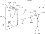
- FIG. 5 a shows a schematic representation illustrating a user interface apparatus 100 according to an exemplary embodiment in use by an exemplary user 200 .
- the user interface apparatus 100 according to the embodiment shown in FIG. 5 a comprises a display screen 108 , and a sensing component 106 .
- the user 200 comprises a hand 200 a , an eye 200 c , and a head 200 b .
- the user is positioned so that the user is facing the display screen 108 , and the hand 200 a is outstretched from the user's body in the direction of the display screen 108 .
- the sensing component 106 comprises three sensors 106 a 106 b and 106 c for tracking the position of the user's hand and the position of the user's head 200 b and/or eye 200 c , and for determining the configuration of the user's hand 100 a , for example, whether the hand 100 a is in an open configuration or a closed configuration.
- the display screen 108 displays selectable objects 108 a and 108 b that are selectable by the user 200 .
- the user 200 interacts with the user interface apparatus 100 using hand 200 a .
- the user 200 obscures from his or her own view the position 202 on the display screen 108 with which he or she wishes to interact.
- the user 200 has hand 200 a positioned such that the region 202 of the display screen 108 is obscured from the user's 200 view.
- the user interface apparatus 100 obtains information relating to a first tracked position, the first tracked position being a position of a first hand (i.e. hand 200 a ) of the user.
- the user interface apparatus 100 also obtains information relating to a second tracked position, the second tracked position being a position of the head 200 b or an eye 200 c of the user 200 .
- a position of the user's hand 200 a i.e. a “first tracked position” and the position of an eye 200 c of the user (an example of a “second tracked position”) may define two points of a straight line 204 , also referred to herein as the eye-hand line 204 .
- a position of an eye 200 c of the user 200 may refer to a position between the eyes of the user (e.g. the midpoint between the eyes of the user), or the position of the centre on an eye, or pupil of an eye of the user.
- the position of the centre of a user's hand 200 a , and the centre of a user's eye 200 c may be used to define the eye-hand line 204 .
- the eye 200 c may be, for example, the dominant eye of the user, i.e. the eye of the user from which visual input is stronger or preferred.
- the dominant eye 200 c may be, for example, identified to the user interface apparatus by suitable input by the user.
- the user interface apparatus may calculate the eye-hand line 204 in its virtual three dimensional space 702 .
- the eye-hand line 204 intersects with the display screen 108 at point 206 , which point 206 is contained within the region 202 of the display screen 108 that is obscured from the user's 200 view by the user's hand 200 a .
- the user interface apparatus 100 may represent the display screen in the same virtual three dimensional space 702 in which the virtual representation of the user 704 is represented, and hence where the eye-hand line 204 is virtually represented.
- the user interface apparatus 100 may determine the point on the display screen in virtual space 702 at which the virtual eye-hand line intersects the display screen in virtual space 702 . In such a way, the user interface apparatus 100 may infer the position on the actual display screen 108 with which the user 200 wishes to interact.
- Alternative positions other than the position of an eye 200 c of the user 200 may be used to define the second tracked position, but which would still result in the eye-hand line 204 intersecting with the display screen 108 in a region 202 of the display screen 108 obscured from the view of the user 200 .
- the midway point between the two eyes 200 c of the user 200 may be used. This may be advantageous as this would allow a point of intersection 206 of the head-hand line 204 with the display screen 108 contained in the region 202 obscured from the user's vision to be determined without requiring a knowledge of which eye 200 c of the user 200 is stronger or preferred or otherwise should be used in defining the head hand line 204 .
- the second tracked position may alternatively be a position of the head 200 b of the user, for example the centre of a user's head 200 b.
- a position of the user's hand 200 a i.e. “first tracked position” and the position of the head 200 b of the user 200 (an example of a “second tracked position”) may define two points of a straight line 204 , referred to in this case as the head-hand line 204 .
- the term “eye-hand line” is used in the various discussions below, in some embodiments a head-hand line is used instead.
- the eyes of the user 200 are typically located approximately halfway down the vertical length of the user's head 200 b , and are set at a substantial depth into the user's head.
- the use of the position of the centre of a user's head 200 b in defining the second tracked position may still result in the head-hand line 204 intersecting with the display screen 108 in a region 202 of the display screen 108 obscured from the view of the user 200 .
- the head-hand line 204 may be used by user interface apparatus 100 in place of eye-hand line 204 when determining the portion of the display screen with which the user wishes to interact.
- Using a position of a user's head as a second tracked position may be advantageous in situations where it is difficult to detect the position of the eyes or an eye of the user, or in situations where it is more efficient to track the centre of a user's head 200 b compared to tracking the position of an eye 200 c or eyes of the user 200 .
- the hand 200 a may be either hand of the user 200 , and may for example be that hand of the user determined to be closest to the display screen 108 , or alternatively or additionally that hand of the user which is the more raised of the two hands of the user 200 .
- the user interface apparatus 100 can determine the eye-hand line 204 (or head-hand line 204 as appropriate), and hence determine a point of intersection 206 of the line 204 with the display screen 108 contained within the region of the display screen 202 obscured from the user's view by the user's hand 200 a . In such a way, the user interface apparatus 100 can determine a position on the display screen 108 with which the user 200 is to interact.
- the second tracked position is the position of a user's head 200 b , for example the position of the centre of the user's head 200 b , rather than an eye position, due to the physical separation of the user's eyes from the centre of a user's head, there may be a discrepancy between the point of intersection 206 of the head-hand line 204 determined by the user interface apparatus 100 , and the centre of the region 202 obscured from the user's vision (i.e. the region that the user intends to select).
- 5 b illustrates schematically a potential offset D between point of intersection 206 a of a head-hand line 204 a (defined using the centre 200 e of the user's head 200 b ), and the point of intersection 206 b of an eye-hand line 204 b (defined using a position of the user's eye 200 c ) according to an example.
- both points of intersection 206 a and 206 b are contained within the region 202 obscured from the user's vision.
- the point of intersection 206 b (determined using the user's eye position) is closer to the centre of the region 202 obscured from the user's vision than the point of intersection 206 a (determined using the user's head position).
- the point of intersection determined using the head-hand line 204 b therefore less consistently results in correct selection of the object intended for selection.
- an eye position e.g. the position of the user's eye 200 c
- a head position e.g. the centre 200 e of a user's head 200 b
- the user interface apparatus 100 may store information relating to the current position of selectable objects on display screen 108 .
- the user interface apparatus 100 may determine that selectable object 108 b displayed on the display screen 108 contains eye-hand line 204 intersection point 206 , meaning that selectable object 108 b is at least partially obscured from the user's view, and therefore determine that selectable object 108 b may be an object to be selected.
- selectable object 108 a does not contain intersection point 206 , and therefore is not determined to be an object to be selected or otherwise of present interest to the user 200 .
- the user may select the object 108 b at least partially obscured from the user's view 200 by changing a configuration of the user's hand 200 a . If the user interface apparatus 100 determines that such a change in configuration of a user's hand 200 a occurs whilst selectable object 108 b contains intersection point 206 , the selectable object 108 b is determined as selected. Further operations can be performed on a selected selectable object as described in more detail below.
- Such determinations as described above may be made, for example, using processor 104 (not shown in FIG. 5 a or 5 b ) and memory 106 (not shown in FIG. 5 a or 5 b ) of the user interface apparatus 100 .
- a user 200 may interact with a displayed object (e.g. selectable objects 108 a , 108 b ) in a way he or she 200 may naturally interact with objects, i.e. typically when selecting (i.e. picking up) an object, a user at least partially covers that object with his or her hand, and hence at least partially obscures that object from his or her view. Further, such an interaction avoids requiring a user to move a pointer displayed on the display screen toward a target because the position of the hand and the position of objects displayed on the screen can be directly and visually inferred from his or her own perspective.
- a displayed object e.g. selectable objects 108 a , 108 b
- Such an intuitive interface therefore obviates the need for a pointer to be displayed, and reduces fatigue in the user compared to interfaces using pointers whereby the user must first move the arm in order to find the pointer, move the pointer toward a target, and then adjust speed and amplitude of movement in order precisely to reach the target.
- FIG. 6 a shows the display screen 108 of the user interface apparatus 100 from the point of view of the user 200 (not shown in FIG. 6 ).
- the positions of the selectable objects 106 a to 106 f on the display screen are determined by the user interface apparatus 100 , for example because the image displayed on the display screen 108 is derived from information generated by the processor 104 of the user interface apparatus 100 .
- the user 200 wishes to select selectable object 108 b .
- the user therefore positions his or her hand 200 a so as to obscure object 108 b from his or her view.
- the user's hand is spread out in a substantially open configuration.
- the user's hand 200 a need not necessarily touch the screen 108 or be any specific distance from display screen 108 , the hand 200 a need only obscure at least a portion of the object 108 b from the user's 200 view.
- the centre of the user's hand 200 a is represented by dot 300 .
- the eye-hand line 204 (not shown in FIG. 6 a ) contains the centre of the user's hand.
- the position 206 on the display screen 108 at which the user's eye-hand line 204 (not shown in FIG. 6 a ) intersects the display screen 108 is therefore, from the user's perspective, aligned with the centre of the user's hand 300 .
- the user interface apparatus 100 may determine that selectable object 108 b contains the intersection point 206 , and may, for example, determine object 108 b as a candidate object for selection by the user 200 . In some embodiments, the user interface apparatus 100 may determine object 108 b as a selected object based solely on a determination that selectable object 108 b contains the intersection point 206 .
- the user interface apparatus 100 may cause the object 108 b to be displayed differently.
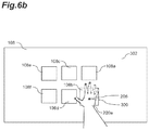
- FIG. 6 b illustrates an exemplary change to selectable object 108 b , where selectable object 108 b is increased in size with respect to its size before it was determined as a candidate object for selection.
- Other changes may be made to an object determined a candidate object for selection, such as, for example, a change of colour, a change of representation of the object, for example the shape of the object, or a complete change in the image symbolising the object.
- the background 302 of the display screen 108 may change, for example change colour or intensity, when such a determination is made.
- a sound may be generated by a sound generating means such as a speaker on determination of an object possible for selection, which sound may be, for example, correlated to the object itself.
- the representation of the panda may change (for example the face of the panda may change from a neutral expression to a smiling expression), the size of the representation may change, and/or a sound of a panda may be generated.
- These changes may advantageously alert the user to the possibility of selecting the object 108 b which is at least partially obscured from the view of the user 200 by the user's hand 200 a.
- no such changes occur on determination that the object is a candidate object for selection. In yet further embodiments, no such determination that an object is a candidate object for selection is made by user interface apparatus 100 .
- FIG. 6 c is an illustration showing a user selecting selectable object 108 b , and is the same as FIG. 6 a , except that the user has performed a grab-like action, in doing so has changed the configuration of the hand 200 a from an out-stretched open configuration to a fist-like closed configuration. Note that the object 108 b still remains at least partially obscured from the user's view.
- the user interface apparatus 100 determines when the configuration of the hand has changed from an open configuration as in the hand 200 a of FIG. 3 b to a closed configuration as in the hand 200 a of FIG. 3 c . In response to such a determination, the user interface apparatus 100 determines the point of intersection 206 of the eye-hand line 204 with the display screen 108 . In response to a determination that the intersection point 206 is located within a selectable object 108 b displayed on the display screen 108 , then the selectable object 108 b is determined as selected by the user. In the example of FIG. 6 c , since the intersection point 206 does lie within the selectable object 108 b as the hand 200 a changes to a closed configuration, then the object 108 b is determined as selected.
- the user interface apparatus 100 need not necessarily determine that a hand configuration of the user has changed in order to determine that a selectable object 108 b is selected.
- the user interface apparatus 100 continuously (or near continuously, e.g. 30 times a second) determines the point of intersection 206 of the eye-hand line 204 with display screen 108 .
- the selectable object 108 b is determined as selected by the user.
- a selectable object 108 b may be selected by a user 200 without a need for the user 200 to change a configuration of his or her hand 200 a .
- the selectable object may be selected on the basis of the intersection point 206 being located within a selectable object 108 b displayed on the display screen 108 for a predetermined duration of time, for example the object may only be determined as selected after the intersection point 206 has been located within the selectable object for 1 second.
- a selectable object 108 b determined as selected may be moved from one location on the display screen 108 to another by the user 200 .
- FIG. 6 d is an illustration of a display screen as viewed from the user's perspective, and is the same as FIG. 6 c , except the user has moved his or her hand 200 a , whilst still in the closed, fist-like configuration, to a different location in his or her field of view, and the position of the selected object 108 b on the display screen 108 has moved accordingly.
- the original position of object 108 b before moving is represented by dashed box 108 b *.
- the position to which the object 108 b is moved depends on the position to which the user has moved his or her hand 200 a , and accordingly the position on the display screen 108 to which the point of intersection 206 of the eye-hand line 204 (not shown in FIG. 6 d ) has moved.
- the object 108 b whilst the object 108 b is selected, even if it is being moved, the object 108 b still contains the point of intersection 206 , and the user's hand 200 a still at least partly obscures the object 108 b from the user's view.
- the object 108 b may be moved outside of the display screen accordingly.
- the object 108 b may be constrained to not leave the display screen 108 , and may for example, in such a case, be automatically deselected.
- the object may remain in a given position, for example the last position where the point of intersection 206 was determined to be within the display screen 108 , until it is determined that the user moves his or her hand 200 a such that the point of intersection 206 returns to within the display screen 108 , at which time the object will return to the point of intersection 206 as so newly determined.
- the user in order to deselect an object 108 b selected as described above, changes the configuration of his or her hand 200 a from a closed configuration (as in FIG. 6 c or 6 d ), back to an open configuration (as in FIG. 6 a ).
- FIG. 6 e shows an illustration of display screen 108 from a user's perspective, and is the same as FIG. 6 d , except the hand 200 a has changed from a closed configuration to an open configuration.
- the user interface apparatus 100 determines that the selected object 108 b is unselected. In the example shown in FIG.
- FIG. 6 f is an illustration of the display screen 108 from the user's 200 perspective, and is the same as FIG. 6 e , except that the user has moved his or her hand 200 a , still in the open configuration, to a different position, but the object 108 b (now deselected) remains in the same position on the display screen 108 .
- the user interface apparatus selects a selectable object 108 b solely on the basis that the point of intersection 206 of the eye-hand line 204 with display screen 108 is located within the selectable object 108 b , or has been so located for a predetermined amount of time, then the user need not maintain his or her hand configuration in a closed configuration (or indeed any particular configuration) in order to move the selected object.
- the object may be deselected automatically, for example, when the user causes the point of intersection 206 to be outside of the display screen.
- the object may be deselected if the user ceases movement of the selected object for a predetermined duration of time, for example if the user interface apparatus 100 determines that, whilst an object is selected, the point of intersection 206 has not moved by more than a predetermined amount (e.g. distance or degree) in the last 1 second, the user interface apparatus 100 may determine that the selected object is deselected.
- a predetermined amount e.g. distance or degree
- an object 108 b may also be selected or deselected on the basis of a determined change in the configuration of the hand 200 a of the user 200 other than a change between an open configuration and a closed configuration or vice versa.
- Any other suitable configuration change which can be reliably detected by the user interface apparatus 100 may be used.
- a suitable change in configuration may be a change in the way in which the palm of an outstretched hand 200 a is facing, for example a change from a configuration where the palm of the hand 200 a is facing towards the display screen 108 to a configuration where the palm of the hand 200 a is facing away from the display screen.
- Another such suitable change in configuration may be a “pinching” action, whereby a user's hand changes from an open configuration with the fingers outstretched to a closed configuration whereby one or more fingers and the thumb of the hand are brought together whilst still being extended radially from the hand.
- Another such suitable change in configuration may be on the occurrence of one or more “tapping” actions, whereby the user's hand changes from an open configuration where the fingers are outstretched, for example in a first plane, for example a plane substantially parallel with the plane of the display screen 108 , to a second configuration where the hand has rotated about the wrist such that the fingers are outstretched, for example, in a second plane rotated with respect to the first plane, for example a plane substantially perpendicular to the plane of the display screen.
- a change in configuration may only be recognised after two or more of these “tapping” actions, such that, for example, a user selects an item by “double tapping” on an object.
- a user 200 may remove or delete a selected virtual object 108 b (or data associated therewith) in a similar way as the user 200 may remove a physical object which he or she is holding: by throwing it away.
- a naturalistic interface has, for example, advantages in the ease with which a user may engage effectively with it.
- Such a “throwing away” action typically comprises a sudden change in position or velocity of the object coupled with the user releasing (deselecting) the object.
- the user interface apparatus 100 may determine the rate at which a user 200 changes the position of his or her hand 200 a in a given direction when a given selectable object 108 b is selected. This can be determined directly by tracking the change in the determined hand 200 a position in three dimensional coordinates, or by tracking the change in point of intersection 206 of the eye-hand line 204 with the display screen 108 . Alternatively the user interface 100 may determine this for example by determining the displacement or distance travelled by the selected object 108 b on the display screen 108 in a given time (i.e. the average velocity or average displacement velocity of the object 108 b over a given time interval).
- the user interface apparatus 100 may additionally or alternatively determine such an average velocity of the object 108 b over a number of such time intervals, and in such a way determine an acceleration of the object 108 b .
- the user interface apparatus 100 determines that a selected selectable object 108 b is unselected (for example as described above with reference to FIG. 6 e ) the velocity of the object 108 b and/or the acceleration of the object 108 b in one or more time period(s) immediately preceding the determination that the selectable object 108 b is unselected is determined.
- the user interface apparatus 100 may compare this determined velocity of the object 108 b and/or determined acceleration of the object 108 b to a predetermined threshold of velocity and/or predetermined threshold of acceleration respectively.
- An exemplary further processing action may be a deletion of the object 108 b . This deletion may correspond to removing the object 108 b from display on the display screen 108 , and/or moving data associated with the object 108 b from one directory of the memory (e.g. memory 106 or 112 ) in which the data is stored to another, and/or removing the data altogether.
- FIG. 7 similarly to FIG. 5 , illustrates a user 200 using a user interface apparatus 100 according to another exemplary embodiment.
- the user interface apparatus comprises a gaze-sensor 110 for use in sensing the gaze direction 404 of the user 200 , comprising glasses 402 worn by the user 200 .
- the glasses 402 may track the rotation of the eye 200 c of the user relative to the glasses 402 , for example by tracking the position of the pupil of the eye using infra-red cameras. Since, in operation, the glasses 402 are fixed relative to the user's head 200 b , the glasses 403 can track the rotation of the eye 200 c relative to the user's head 200 b .
- the gaze sensor 110 may comprise other components (not shown) for determining the gaze direction 404 of the user 200 relative to the display screen 108 . These components may comprise, for example, magnetometers to track the change in orientation of the head of the user 200 b with respect to a given direction.
- gaze sensor 110 may comprise any other suitable technology for determining the gaze direction of the user relative to the display screen 108 .
- the user interface apparatus 100 may determine a point 406 on the display screen at which the user is looking by extrapolating determined gaze direction 404 from the determined tracked position of the user's eye 200 c in three dimensional space.
- region 202 of the display screen 180 is still obscured from the user's view by the user's hand 200 a .
- the user interface apparatus 100 still determines the point of intersection 206 of the eye-hand line 204 with the display screen 108 as a point for use in controlling selectable objects 108 a or 108 b displayed on the display screen 108 .
- the point of intersection 206 of the eye-hand line 204 with the display screen 108 is such that it is contained within selectable object 108 b .
- the point 406 on the display screen 108 at which the user 200 is looking is separated from the point of intersection 206 of the eye-hand line 204 with the display screen 108 by a distance d (not shown in FIG. 7 ).
- the object 108 b is selected by the user. If it is determined that the object 108 b is unselected by the user (for example if the user interface apparatus determined that the configuration of the user's hand 200 a changes from a closed configuration to an open configuration) then the user interface apparatus 100 determines the distance d between the point 406 and the point 206 . If it is determined that the distance d is above a predetermined threshold, the user interface apparatus may perform a further processing operation on the object 108 b , and if it is determined to be below the predetermined threshold then it may not perform a further processing operation.
- the further processing operation may be, for example, a deletion of the object as described above, or may be any other conceivable further processing operation, for example: save, copy, zoom, rotate, resize etc.
- the user interface apparatus may determine that the point of intersection 206 of the eye-hand line 204 and the point 406 on the display screen 108 at which the user is looking are held separated a distance d from each other by more than a threshold amount, for more than a threshold amount of time. For example, a user 200 may hold his or her hand 200 a in one position whilst his or her gaze is held directed at a different position on the display screen 108 , for example, for more than 1 second. Upon such a determination, the user interface apparatus 100 may determine that a further processing action should be performed, for example, to re-arrange all of the selectable objects 108 a , 108 b etc.
- the user may control the user interface apparatus 100 to position the selectable objects 108 a , 108 b , etc. such that, for example, they may be more easily and readily distinguished and selected by the user 200 .
- the user interface apparatus 100 can obtain more degrees of control from the user 200 , and as such provide a more efficient interface with which the user 200 may interact.
- the user interface apparatus 100 may determine that the user 200 has a low competence level in using the user interface apparatus 100 , e.g. that the user 200 is a beginner, and may not be used to the control paradigm provided by user interface apparatus 100 .
- the user interface apparatus may determine that the user 200 has changed the configuration of his or her hand 200 a from an open configuration to a closed configuration (i.e. signifying to select an object) at a position on the display screen at which there is no selectable object 108 b to select.
- the user interface apparatus 100 may determine that such an occurrence has happened successively more than a predetermined number of times.
- the user interface apparatus 100 may cause a pointer, or some symbolic indicator to be displayed on the display screen at a position related to the determined point of intersection 206 in order that the user may be reminded of the location on the display screen with which he or she is interacting.
- the pointer may only be displayed for a predetermined period of time, for example 5 seconds to allow the user to orientate themselves with the display screen.
- the pointer may only be displayed for a predetermined number of determined changes in hand configuration of the user, or otherwise until such time as the user 200 successfully selects an object 108 b .
- the pointer may be arranged such that it is not obscured from the view of the user 200 by the user's hand 200 a when it is displayed on the display screen.
- Such an exemplary pointer is shown in FIG. 8 , which shows display screen 108 displaying selectable objects 108 a to 108 f , and also displaying circular pointer 802 centred on the determined point of intersection 206 , and with a large enough diameter so as to not be completely obscured from the user's view by the user's hand 200 a.
- the user interface apparatus 100 may additionally or alternatively determine a low competence level, if an action is repeated by a user more than a predetermined number of times. For example, if a user selects an object, moves it, and then replaces the object to at or nearby its original position, say, more than three times successively, this may be indicative of a user selecting an object other than the object he or she intends to select, and the user interface apparatus 100 may determine a low competence level and display a pointer as described above accordingly to remind the user of the control paradigm.
- the dimensions and position of the screen 108 in virtual three dimensional space 702 is determined by the user interface apparatus in a calibration procedure.
- the point of intersection of two determined eye-hand lines 204 associated with a user 200 standing in two different positions is used by user interface apparatus 100 to infer a three dimensional coordinate of the display screen 108 .
- FIG. 9 shows an illustration of a portion of such a calibration process, where a user 200 stands in two different locations 901 and 902 , and in each location positions his or her hand 200 a into a position so as to obscure from his or her view, a predetermined location 904 on the display screen 108 .
- the user interface apparatus 100 may cause to be displayed on display screen 108 instructions instructing the user to position his or her hand 200 a so as to obscure a given symbol 904 indicated on the display screen, for example located at a corner of the display screen 108 , and once in place to perform a “grab-action” i.e. change his or her hand 200 a from an open configuration to a closed configuration.
- a “grab-action” i.e. change his or her hand 200 a from an open configuration to a closed configuration.
- the user interface apparatus 100 may record the eye-hand line 910 in virtual space 702 .
- the user interface apparatus 100 may then cause to be displayed instructions for the user to repeat this process (not shown in FIG.
- the user interface apparatus 100 may then cause to be displayed instructions for the user to repeat this process, but from a different location, for example location 902 , and in such a way determine the dimensions and position in virtual space 702 of the display screen 108 , as described in more detail below.
- the respective resulting two eye-hand lines 910 and 920 (produced when user 200 obscures region 904 from his or her view and performs a grab-action when standing at locations 901 and 902 respectively), have a point of intersection, or near intersection at point 906 .
- the user interface apparatus 100 For each location 901 and 902 , the user interface apparatus 100 , using sensor component 106 , determines a representation 704 of the user in three dimensional virtual space 702 , and from this determines the eye-hand line ( 910 or 920 ) in virtual three dimensional space 702 , as described above.
- Such an intersection point can then be used to define the three dimensional coordinates of the region of the display screen 108 in virtual space 702 corresponding to region 904 on display screen 108 .
- the user instead of the user only obscuring one region 904 of the display screen 108 with his or her hand 200 a , at each location 901 and 902 , the user sequentially obscures two or more regions of the display screen, for example two corners of the display screen 108 . In this case, two or more coordinates of the display screen 108 can be determined in virtual space 702 .
- the exact dimensions and position of the display screen in virtual space 702 can be determined. This is because if it is predetermined that the screen is rectangular, then the position of the fourth corner of the display screen 108 can be inferred from the positions of the other three corners. If the shape of the display screen 108 is not predetermined, then more regions of the display screen may be included in the calibration process until an appropriate mapping of the position of the display screen to three dimensional virtual space 702 coordinates is achieved.
- two eye-hand lines L 1 and L 2 may not actually intersect, and may only near-intersect.
- the intersection point 906 may be determined as the midway of the shortest line connecting L 1 and L 2 .
- the parameters t 1c and t 2c define the points P 1 (t 1c ) and P 2 (t 2c ) respectively, which can then be used to define the segment [P 1 (t 1c ), P 2 (t 2c )].
- the centre of the segment [P 1 (t 1c ), P 2 (t 2c )] can then be used to define the point of near intersection, and hence the position in virtual
- the position of the region 904 in virtual space 702 can be determined by the user interface apparatus 100 .
- the user interface apparatus may determine that the length of the segment [P 1 (t 1c ), P 2 (t 2c )] is above a certain threshold, and hence that the inferred point of near intersection in virtual space is likely to be a poor representation of the corresponding region 904 of the display screen 108 .
- the calibration process may be repeated until the length of all segments corresponding to respective near intersection of the calibration process is less than a certain threshold.
- the display screen displays a dynamic measurement of the shortest distance between lines 910 and 920 , so that the user may position his or her hand so as to minimise this measurement, and hence produce a more accurate calibration.
- an indication of whether the shortest distance is within an acceptable range, for example, less than 5 cm, is displayed.
- the user interface apparatus 100 only records an eye-hand line (e.g. 901 , 902 ) in a calibration process if it is stable enough to provide an suitably accurate determination of screen position, for example only if the corresponding eye and hand positions are stable to within 2 cm for a 10 second period.
- an eye-hand line e.g. 901 , 902
- the user interface apparatus 100 can accurately determine the intersection point 206 with which a user 200 wishes to interact, for any such user, independent of the user's dimensions, body type, etc.
- the calibration steps described above with reference to region FIGS. 9 and 10 are repeated, for example, for corners 904 , 908 , and 912 of display screen 108 , such that the user interface apparatus 100 determines the three dimensional coordinates (A, B, C) of corners 912 , 908 , and 904 respectively in virtual space 701 .
- the user interface apparatus 100 may determine a eye-hand line 204 defined in three dimensional virtual space 702 by eye-hand line L (E,H) of equation 1 containing points P(t).
- the user interface apparatus 100 may determine the position on the display screen 108 at which the user wishes to interact by calculating the point of intersection P of eye-hand line L (E,H) and the plane (A, B, C) in virtual space 702 .
- the 2D coordinates of the point P within the 2D display screen may be calculated, for example for use as an input to an application requiring the 2D coordinates of the point of user interaction on a display screen 108 .
- the user interface apparatus 100 may calculate the coordinate transformation needed to define A as the origin, AB/
- Such a coordinate transformation may comprise a translation and three rotations as described below.
- the user interface apparatus 100 may define one of the coordinates of the corners, for example A, as an origin O of the virtual space 702 .
- the translation required from A to the origin O of the virtual space 702 is calculated.
- Three rotations to compensate for the three possible rotations about this origin the plane (A, B, C) may then be calculated.
- an edge of the screen for example the bottom edge of the screen defined by AB is projected onto the plane (O, x, z) in coordinate system of the virtual space 702 , where O is the origin, x is the x axis vector and z is the z axis vector in virtual space 702 .
- the angle ⁇ between x and the projection of AB on (O, x, z) may then be calculated using:
- the above calculated transformations may then be applied to three dimensional intersection coordinate P in order to transform it to a two dimensional coordinate P′ within the display screen.
- head-hand lines may be used by user interface apparatus 100 in the calibration process instead.
- the user interface apparatus may detect and track multiple users at the same time.
- the user interface apparatus 100 may track the positions of multiple user's and correspondingly determine and carry out interactions with the display screen 108 for each individual user.
- user interface apparatus 100 may determine an “active user”, and only obtain and/or use tracking information relating to that user.
- An active user may be determined for example as the user that is located the shortest distance from the display screen 108 , for example based on the determined hip joint location of the virtual representation 704 of each user in virtual space 702 .
- FIG. 11 shows a schematic flow diagram of steps in a method performed by a user interface apparatus 100 to allow a user to select selectable objects 108 b displayed on a display screen 108 according to an embodiment.
- Step S 1101 comprises tracking a hand 200 a position, the hand position being a position of a first hand 200 a of a user, tracking a head 200 b or an eye 100 c position of the user, and detecting hand configuration of the first hand 200 a.
- Step S 1102 comprises determining one or more object 108 b positions of the one or more selectable objects 108 b on the display screen 108 .
- Step S 1103 comprises determining when the detected hand configuration of the first hand 200 a of the user 200 has changed to a first predetermined configuration, for example to a closed, first like configuration. If the detected hand configuration has changed to a first predetermined configuration, then the method proceeds to step S 1104 , and if it hasn't then the method returns to step S 1101 .
- Step S 1104 comprises determining, responsive to a determination that the detected hand configuration has changed to the first predetermined configuration, and based on the tracked hand 200 a position, the tracked head 200 b or eye 200 c position and the determined one or more object 108 b positions, whether a said selectable object 108 b is located at a first screen position, the first screen position being a position on the display screen 108 such that the first hand 200 a at least partly obscures the user's view of the selectable object 108 b . If it is determined that the selectable object is located at the first screen position, then the method progresses to step S 1105 , and if it is not, the method returns to step S 1101 . In some embodiments, alternatively, if it is determined that there is no selectable object located at the first screen position, then the user interface apparatus may determine a low competence level of the user, and may for example display a pointer as described above.
- Step S 1105 comprises, (in the case of a determination that the first hand does at least partly obscure the user's view of the selectable object) determining that the selectable object is selected.
- Such a method as described above may be for example, written into code executable by a user interface apparatus 100 , or any other suitable processing system, which code may be stored on a computer readable medium, and which when executed by the user interface apparatus 100 or suitable processing system, causes the user interface apparatus 100 or suitable processing system to perform the method as described above.
Landscapes
- Engineering & Computer Science (AREA)
- General Engineering & Computer Science (AREA)
- Theoretical Computer Science (AREA)
- Human Computer Interaction (AREA)
- Physics & Mathematics (AREA)
- General Physics & Mathematics (AREA)
- User Interface Of Digital Computer (AREA)
- Position Input By Displaying (AREA)
Applications Claiming Priority (1)
| Application Number | Priority Date | Filing Date | Title |
|---|---|---|---|
| PCT/JP2015/062316 WO2016166902A1 (fr) | 2015-04-16 | 2015-04-16 | Interface gestuelle |
Publications (2)
| Publication Number | Publication Date |
|---|---|
| US20180088676A1 US20180088676A1 (en) | 2018-03-29 |
| US10969872B2 true US10969872B2 (en) | 2021-04-06 |
Family
ID=53177336
Family Applications (1)
| Application Number | Title | Priority Date | Filing Date |
|---|---|---|---|
| US15/566,780 Active US10969872B2 (en) | 2015-04-16 | 2015-04-16 | Gesture interface |
Country Status (5)
| Country | Link |
|---|---|
| US (1) | US10969872B2 (fr) |
| EP (1) | EP3283938B1 (fr) |
| JP (1) | JP6343718B2 (fr) |
| ES (1) | ES2835598T3 (fr) |
| WO (1) | WO2016166902A1 (fr) |
Families Citing this family (16)
| Publication number | Priority date | Publication date | Assignee | Title |
|---|---|---|---|---|
| KR102465804B1 (ko) * | 2015-05-12 | 2022-11-10 | 엘지전자 주식회사 | 영상표시장치 및 그것의 제어방법 |
| WO2016200197A1 (fr) * | 2015-06-10 | 2016-12-15 | (주)브이터치 | Procédé et appareil de détection de geste dans un système de coordonnées dans l'espace basé sur un utilisateur |
| US10466780B1 (en) * | 2015-10-26 | 2019-11-05 | Pillantas | Systems and methods for eye tracking calibration, eye vergence gestures for interface control, and visual aids therefor |
| US20180004385A1 (en) * | 2016-06-30 | 2018-01-04 | Futurewei Technologies, Inc. | Software defined icon interactions with multiple and expandable layers |
| JP6996296B2 (ja) | 2017-12-28 | 2022-01-17 | 住友ゴム工業株式会社 | ゴルフボール |
| US10706300B2 (en) * | 2018-01-23 | 2020-07-07 | Toyota Research Institute, Inc. | Vehicle systems and methods for determining a target based on a virtual eye position and a pointing direction |
| US10817068B2 (en) * | 2018-01-23 | 2020-10-27 | Toyota Research Institute, Inc. | Vehicle systems and methods for determining target based on selecting a virtual eye position or a pointing direction |
| US10853674B2 (en) | 2018-01-23 | 2020-12-01 | Toyota Research Institute, Inc. | Vehicle systems and methods for determining a gaze target based on a virtual eye position |
| US10831265B2 (en) * | 2018-04-20 | 2020-11-10 | Microsoft Technology Licensing, Llc | Systems and methods for gaze-informed target manipulation |
| CN110554784B (zh) * | 2018-05-31 | 2023-07-14 | 广东虚拟现实科技有限公司 | 输入方法、装置、显示设备及存储介质 |
| WO2019244270A1 (fr) * | 2018-06-20 | 2019-12-26 | 三菱電機株式会社 | Dispositif d'acquisition de coordonnées oculaires tridimensionnelles et dispositif d'opération gestuelle |
| CN109407831A (zh) * | 2018-09-28 | 2019-03-01 | 维沃移动通信有限公司 | 一种交互方法及终端 |
| KR20190106851A (ko) * | 2019-08-27 | 2019-09-18 | 엘지전자 주식회사 | Xr 컨텐츠 제공 방법 및 xr 컨텐츠 제공 디바이스 |
| US11630639B2 (en) * | 2020-12-08 | 2023-04-18 | Samsung Electronics Co., Ltd. | Control method of electronic device using a plurality of sensors and electronic device thereof |
| JP2023135920A (ja) * | 2022-03-16 | 2023-09-29 | パナソニックIpマネジメント株式会社 | 制御装置および制御方法 |
| JP2024018746A (ja) | 2022-07-29 | 2024-02-08 | フォルシアクラリオン・エレクトロニクス株式会社 | データ処理装置及びデータ処理方法 |
Citations (13)
| Publication number | Priority date | Publication date | Assignee | Title |
|---|---|---|---|---|
| JP2002259989A (ja) | 2001-03-02 | 2002-09-13 | Gifu Prefecture | ポインティングジェスチャ検出方法及びその装置 |
| US20100156781A1 (en) * | 2008-12-19 | 2010-06-24 | Samsung Electronics Co., Ltd. | Eye gaze control during avatar-based communication |
| US20120206333A1 (en) | 2011-02-16 | 2012-08-16 | Seok-Joong Kim | Virtual touch apparatus and method without pointer on screen |
| US20120249422A1 (en) * | 2011-03-31 | 2012-10-04 | Smart Technologies Ulc | Interactive input system and method |
| US20130154913A1 (en) * | 2010-12-16 | 2013-06-20 | Siemens Corporation | Systems and methods for a gaze and gesture interface |
| US20140198031A1 (en) | 2013-01-16 | 2014-07-17 | Huaixin XIONG | Palm gesture recognition method and device as well as human-machine interaction method and apparatus |
| US8947351B1 (en) | 2011-09-27 | 2015-02-03 | Amazon Technologies, Inc. | Point of view determinations for finger tracking |
| US20150193107A1 (en) * | 2014-01-09 | 2015-07-09 | Microsoft Corporation | Gesture library for natural user input |
| US20160162082A1 (en) * | 2014-12-03 | 2016-06-09 | Microsoft Technology Licensing, Llc | Pointer projection for natural user input |
| US20160224109A1 (en) * | 2013-09-16 | 2016-08-04 | Lg Electronics Inc. | Image display apparatus and method for operating the same |
| US20160370865A1 (en) * | 2014-12-26 | 2016-12-22 | Nextedge Technology K.K. | Operation Input Device, Operation Input Method, and Program |
| US20170323158A1 (en) * | 2016-05-03 | 2017-11-09 | John C. Gordon | Identification of Objects in a Scene Using Gaze Tracking Techniques |
| US10168789B1 (en) * | 2017-05-31 | 2019-01-01 | Meta Company | Systems and methods to facilitate user interactions with virtual content having two-dimensional representations and/or three-dimensional representations |
-
2015
- 2015-04-16 WO PCT/JP2015/062316 patent/WO2016166902A1/fr active Application Filing
- 2015-04-16 JP JP2017533050A patent/JP6343718B2/ja active Active
- 2015-04-16 ES ES15722363T patent/ES2835598T3/es active Active
- 2015-04-16 US US15/566,780 patent/US10969872B2/en active Active
- 2015-04-16 EP EP15722363.7A patent/EP3283938B1/fr active Active
Patent Citations (14)
| Publication number | Priority date | Publication date | Assignee | Title |
|---|---|---|---|---|
| JP2002259989A (ja) | 2001-03-02 | 2002-09-13 | Gifu Prefecture | ポインティングジェスチャ検出方法及びその装置 |
| US20100156781A1 (en) * | 2008-12-19 | 2010-06-24 | Samsung Electronics Co., Ltd. | Eye gaze control during avatar-based communication |
| US20130154913A1 (en) * | 2010-12-16 | 2013-06-20 | Siemens Corporation | Systems and methods for a gaze and gesture interface |
| US20120206333A1 (en) | 2011-02-16 | 2012-08-16 | Seok-Joong Kim | Virtual touch apparatus and method without pointer on screen |
| US20120249422A1 (en) * | 2011-03-31 | 2012-10-04 | Smart Technologies Ulc | Interactive input system and method |
| US8947351B1 (en) | 2011-09-27 | 2015-02-03 | Amazon Technologies, Inc. | Point of view determinations for finger tracking |
| JP2014137818A (ja) | 2013-01-16 | 2014-07-28 | Ricoh Co Ltd | 手の平開閉動作識別方法と装置、マン・マシン・インタラクション方法と設備 |
| US20140198031A1 (en) | 2013-01-16 | 2014-07-17 | Huaixin XIONG | Palm gesture recognition method and device as well as human-machine interaction method and apparatus |
| US20160224109A1 (en) * | 2013-09-16 | 2016-08-04 | Lg Electronics Inc. | Image display apparatus and method for operating the same |
| US20150193107A1 (en) * | 2014-01-09 | 2015-07-09 | Microsoft Corporation | Gesture library for natural user input |
| US20160162082A1 (en) * | 2014-12-03 | 2016-06-09 | Microsoft Technology Licensing, Llc | Pointer projection for natural user input |
| US20160370865A1 (en) * | 2014-12-26 | 2016-12-22 | Nextedge Technology K.K. | Operation Input Device, Operation Input Method, and Program |
| US20170323158A1 (en) * | 2016-05-03 | 2017-11-09 | John C. Gordon | Identification of Objects in a Scene Using Gaze Tracking Techniques |
| US10168789B1 (en) * | 2017-05-31 | 2019-01-01 | Meta Company | Systems and methods to facilitate user interactions with virtual content having two-dimensional representations and/or three-dimensional representations |
Non-Patent Citations (6)
| Title |
|---|
| Chatterjee, I., Harrison, C., (2015) Gaze+Gestire: Expressive, Precise and Targeted Free-Space Interactions. * |
| Chatterjee, I., Harrison, C., (2015) Gaze+Gesture: Expressive, Precise and Targeted Free-Space Interactions (Year: 2015). * |
| International Search Report dated Feb. 24, 2016, issued by the International Searching Authority in application No. PCT/JP2015/062316. |
| Rozado, D., Hales, J., Mardanbergi, D., (2013) Interacting with Objects in the ENvironment by Gaze and Hand Gestures (Year: 2013). * |
| Rozado, D., Hales, J., Mardanbergi, D., (2013) Interacting with Objects in the Environment by Gaze and Hand Gestures. * |
| Written Opinion of the International Searching Authority dated Feb. 24, 2016, issued by the International Searching Authority in application No. PCT/JP2015/062316. |
Also Published As
| Publication number | Publication date |
|---|---|
| EP3283938B1 (fr) | 2020-10-07 |
| EP3283938A1 (fr) | 2018-02-21 |
| JP6343718B2 (ja) | 2018-06-13 |
| JP2017539035A (ja) | 2017-12-28 |
| WO2016166902A1 (fr) | 2016-10-20 |
| US20180088676A1 (en) | 2018-03-29 |
| ES2835598T3 (es) | 2021-06-22 |
Similar Documents
| Publication | Publication Date | Title |
|---|---|---|
| US10969872B2 (en) | Gesture interface | |
| US11157725B2 (en) | Gesture-based casting and manipulation of virtual content in artificial-reality environments | |
| US10191559B2 (en) | Computer interface for manipulated objects with an absolute pose detection component | |
| US9503681B1 (en) | Simulated transparent display with augmented reality for remote collaboration | |
| CN106662925B (zh) | 使用头戴式显示器设备的多用户注视投影 | |
| US20210011556A1 (en) | Virtual user interface using a peripheral device in artificial reality environments | |
| EP3227760B1 (fr) | Projection de pointeur destiné à une entrée d'utilisateur naturelle | |
| CN102915112B (zh) | 用于近距离动作跟踪的系统和方法 | |
| US9041775B2 (en) | Apparatus and system for interfacing with computers and other electronic devices through gestures by using depth sensing and methods of use | |
| EP1292877B1 (fr) | Dispositif et procede servant a indiquer une cible par traitement d'image sans modelisation tridimensionnelle | |
| CN107004279A (zh) | 自然用户界面相机校准 | |
| KR101830793B1 (ko) | 상체 상호작용을 이용한 가상훈련 시스템 | |
| US10921879B2 (en) | Artificial reality systems with personal assistant element for gating user interface elements | |
| TW201508561A (zh) | 用於移動追蹤的光斑感測 | |
| JP6369842B2 (ja) | 多深度間隔の再合焦方法および装置および電子デバイス | |
| US10497179B2 (en) | Apparatus and method for performing real object detection and control using a virtual reality head mounted display system | |
| US20140002348A1 (en) | Measuring device and measuring method | |
| US11043192B2 (en) | Corner-identifiying gesture-driven user interface element gating for artificial reality systems | |
| US10852839B1 (en) | Artificial reality systems with detachable personal assistant for gating user interface elements | |
| Hernoux et al. | A seamless solution for 3D real-time interaction: design and evaluation | |
| US11182580B2 (en) | Fingertip identification for gesture control | |
| US8232964B2 (en) | Apparatus for operating objects and a method for identifying markers from digital image frame data | |
| US20070200847A1 (en) | Method And Device For Controlling A Virtual Reality Graphic System Using Interactive Techniques | |
| JP2008226279A (ja) | 仮想空間内位置指示装置 | |
| JP2017103607A (ja) | 画像処理装置、画像処理方法及びプログラム |
Legal Events
| Date | Code | Title | Description |
|---|---|---|---|
| AS | Assignment |
Owner name: RAKUTEN, INC., JAPAN Free format text: ASSIGNMENT OF ASSIGNORS INTEREST;ASSIGNORS:ACH, LAURENT;PREPIN, KEN;LEJEUNE, CECILIA;REEL/FRAME:043871/0756 Effective date: 20150602 |
|
| FEPP | Fee payment procedure |
Free format text: ENTITY STATUS SET TO UNDISCOUNTED (ORIGINAL EVENT CODE: BIG.); ENTITY STATUS OF PATENT OWNER: LARGE ENTITY |
|
| STPP | Information on status: patent application and granting procedure in general |
Free format text: NON FINAL ACTION MAILED |
|
| STPP | Information on status: patent application and granting procedure in general |
Free format text: RESPONSE TO NON-FINAL OFFICE ACTION ENTERED AND FORWARDED TO EXAMINER |
|
| STPP | Information on status: patent application and granting procedure in general |
Free format text: FINAL REJECTION MAILED |
|
| STPP | Information on status: patent application and granting procedure in general |
Free format text: ADVISORY ACTION MAILED |
|
| STPP | Information on status: patent application and granting procedure in general |
Free format text: NON FINAL ACTION MAILED |
|
| STPP | Information on status: patent application and granting procedure in general |
Free format text: RESPONSE TO NON-FINAL OFFICE ACTION ENTERED AND FORWARDED TO EXAMINER |
|
| STPP | Information on status: patent application and granting procedure in general |
Free format text: PUBLICATIONS -- ISSUE FEE PAYMENT RECEIVED |
|
| STPP | Information on status: patent application and granting procedure in general |
Free format text: PUBLICATIONS -- ISSUE FEE PAYMENT VERIFIED |
|
| STCF | Information on status: patent grant |
Free format text: PATENTED CASE |
|
| AS | Assignment |
Owner name: RAKUTEN GROUP, INC., JAPAN Free format text: CHANGE OF NAME;ASSIGNOR:RAKUTEN, INC.;REEL/FRAME:058314/0657 Effective date: 20210901 |