US10945181B2 - Autonomous connection switching in a wireless communication network - Google Patents
Autonomous connection switching in a wireless communication network Download PDFInfo
- Publication number
- US10945181B2 US10945181B2 US15/114,163 US201415114163A US10945181B2 US 10945181 B2 US10945181 B2 US 10945181B2 US 201415114163 A US201415114163 A US 201415114163A US 10945181 B2 US10945181 B2 US 10945181B2
- Authority
- US
- United States
- Prior art keywords
- access point
- connection
- target access
- access points
- target
- Prior art date
- Legal status (The legal status is an assumption and is not a legal conclusion. Google has not performed a legal analysis and makes no representation as to the accuracy of the status listed.)
- Active
Links
- 238000004891 communication Methods 0.000 title claims abstract description 77
- 238000013475 authorization Methods 0.000 claims description 87
- 238000000034 method Methods 0.000 claims description 78
- 230000004044 response Effects 0.000 claims description 32
- 238000005259 measurement Methods 0.000 description 30
- 238000005516 engineering process Methods 0.000 description 9
- 238000004590 computer program Methods 0.000 description 6
- 230000003993 interaction Effects 0.000 description 6
- 238000012544 monitoring process Methods 0.000 description 6
- 230000000694 effects Effects 0.000 description 4
- 230000011664 signaling Effects 0.000 description 3
- 230000003068 static effect Effects 0.000 description 3
- 230000001960 triggered effect Effects 0.000 description 3
- 230000009471 action Effects 0.000 description 2
- 230000001413 cellular effect Effects 0.000 description 2
- 238000010586 diagram Methods 0.000 description 2
- 238000011156 evaluation Methods 0.000 description 2
- 238000013507 mapping Methods 0.000 description 2
- 230000008569 process Effects 0.000 description 2
- 238000012545 processing Methods 0.000 description 2
- 239000007787 solid Substances 0.000 description 2
- 230000009286 beneficial effect Effects 0.000 description 1
- 230000015556 catabolic process Effects 0.000 description 1
- 230000003247 decreasing effect Effects 0.000 description 1
- 238000006731 degradation reaction Methods 0.000 description 1
- 230000007774 longterm Effects 0.000 description 1
- 238000012986 modification Methods 0.000 description 1
- 230000004048 modification Effects 0.000 description 1
- 230000007704 transition Effects 0.000 description 1
Images


Classifications
-
- H—ELECTRICITY
- H04—ELECTRIC COMMUNICATION TECHNIQUE
- H04W—WIRELESS COMMUNICATION NETWORKS
- H04W36/00—Hand-off or reselection arrangements
- H04W36/0005—Control or signalling for completing the hand-off
- H04W36/0011—Control or signalling for completing the hand-off for data sessions of end-to-end connection
- H04W36/0016—Hand-off preparation specially adapted for end-to-end data sessions
-
- H—ELECTRICITY
- H04—ELECTRIC COMMUNICATION TECHNIQUE
- H04W—WIRELESS COMMUNICATION NETWORKS
- H04W36/00—Hand-off or reselection arrangements
- H04W36/24—Reselection being triggered by specific parameters
- H04W36/30—Reselection being triggered by specific parameters by measured or perceived connection quality data
- H04W36/305—Handover due to radio link failure
-
- H—ELECTRICITY
- H04—ELECTRIC COMMUNICATION TECHNIQUE
- H04W—WIRELESS COMMUNICATION NETWORKS
- H04W36/00—Hand-off or reselection arrangements
- H04W36/0005—Control or signalling for completing the hand-off
- H04W36/0055—Transmission or use of information for re-establishing the radio link
- H04W36/0061—Transmission or use of information for re-establishing the radio link of neighbour cell information
-
- H—ELECTRICITY
- H04—ELECTRIC COMMUNICATION TECHNIQUE
- H04W—WIRELESS COMMUNICATION NETWORKS
- H04W36/00—Hand-off or reselection arrangements
- H04W36/0005—Control or signalling for completing the hand-off
- H04W36/0055—Transmission or use of information for re-establishing the radio link
- H04W36/0072—Transmission or use of information for re-establishing the radio link of resource information of target access point
-
- H—ELECTRICITY
- H04—ELECTRIC COMMUNICATION TECHNIQUE
- H04W—WIRELESS COMMUNICATION NETWORKS
- H04W36/00—Hand-off or reselection arrangements
- H04W36/08—Reselecting an access point
-
- H—ELECTRICITY
- H04—ELECTRIC COMMUNICATION TECHNIQUE
- H04W—WIRELESS COMMUNICATION NETWORKS
- H04W36/00—Hand-off or reselection arrangements
- H04W36/24—Reselection being triggered by specific parameters
- H04W36/30—Reselection being triggered by specific parameters by measured or perceived connection quality data
-
- H—ELECTRICITY
- H04—ELECTRIC COMMUNICATION TECHNIQUE
- H04W—WIRELESS COMMUNICATION NETWORKS
- H04W36/00—Hand-off or reselection arrangements
- H04W36/24—Reselection being triggered by specific parameters
- H04W36/32—Reselection being triggered by specific parameters by location or mobility data, e.g. speed data
- H04W36/324—Reselection being triggered by specific parameters by location or mobility data, e.g. speed data by mobility data, e.g. speed data
-
- H—ELECTRICITY
- H04—ELECTRIC COMMUNICATION TECHNIQUE
- H04W—WIRELESS COMMUNICATION NETWORKS
- H04W36/00—Hand-off or reselection arrangements
- H04W36/24—Reselection being triggered by specific parameters
- H04W36/249—Reselection being triggered by specific parameters according to timing information
Definitions
- the present invention relates to methods for managing a connection between a user equipment and a wireless communication network and to corresponding devices.
- HO handover
- the UE which is in a mode referred to as “RRC_connected”, i.e., has an active connection to the cellular network, typically monitors a set of neighboring cells. These measurements may trigger sending of a measurement report from the UE to its serving base station, in the LTE technology referred to as eNB (evolved Node B).
- eNB evolved Node B
- Event A3 corresponds to the measurement result for the neighboring cell being better than the present serving cell plus an offset.
- the measurement result may for example be expressed in terms of Reference Signal Received Power (RSRP) or Reference Signal Received Quality (RSRQ).
- RSRP Reference Signal Received Power
- RSRQ Reference Signal Received Quality
- the triggering event further requires that such condition is met for a certain minimum duration, specified by a parameter referred to as “timeToTrigger”.
- timeToTrigger On the basis of the measurement report, the serving eNB decides whether a HO of the UE should be performed or not. When deciding to perform a HO of the UE, the serving eNB prepares the HO by sending a HO request to an eNB controlling a target cell for the HO.
- the serving eNB also provides context information of the UE, e.g., concerning a current Access Stratum (AS) configuration and UE-specific Radio Resource Management (RRM) information.
- AS Access Stratum
- RRM Radio Resource Management
- the eNB controlling the target cell generates a HO command.
- the serving eNB then forwards the HO command to the UE. This is done in a transparent manner, i.e., the information provided to the UE is determined at the eNB controlling the target cell and not modified by the serving eNB.
- the HO command which is sent to the UE for example includes the identity, and optionally the frequency, of the target cell and RRC information common to all UEs in the target cell, such as information required to perform a random access, a dedicated radio resource configuration; a security configuration, or a cell-specific radio network temporary identity (C-RNTI) to be used in the target cell.
- the UE may then proceed by performing a random access to the target cell. If the random access is successful, the UE confirms successful completion of the HO to the eNB controlling the target cell, which then becomes the new serving eNB for the UE.
- a network initiated HO may also be performed without a preceding Event A3 and measurement report from the UE. In such a case, the UE does not know the target cell before receiving the HO command from the serving eNB.
- the above-mentioned known HO procedure requires rather complex interaction between the serving eNB, the eNB controlling the target cell, and the UE, which means that such a HO can be time consuming.
- Ultra Dense Network To meet future demands on wireless communication networks, a network deployment referred to as Ultra Dense Network (UDN) is being discussed (see, e.g., Ericsson White Paper “5G Radio Access”, June 2013, published in the Internet). For such a UDN it is suggested to use a large number of densely deployed access points (APs) and to utilize higher bandwidths and higher frequency bands than for example in the LTE technology, e.g., a bandwidth of several 100 MHz or even up to the GHz range and a frequency band in the range of 10-100 GHz.
- APs densely deployed access points
- a typical application scenario for a UDN deployment is in highly populated areas such as hot spots, office buildings, or urban centers, which may have a demand of high data rate service.
- a method of managing a connection between a UE and a wireless communication network is provided.
- an access point of the communication network serves the connection to the UE.
- the access point determines a plurality of target access points.
- the access point sends a message to the UE.
- the message indicates the plurality of target access points and authorizes the UE to autonomously switch the connection to one or more of the target access points.
- a method of managing a connection between a UE and a wireless communication network is provided.
- a UE receives a message from an access point of the communication network, which access point currently serves the connection of the UE to the wireless communication network.
- the message indicates a plurality of target access points and authorizes the UE to autonomously switch the connection to one or more of the indicated target access points.
- the UE further detects a triggering event. In response to detecting the triggering event, the UE switches the connection to one or more of the target access points.
- an access point for a wireless communication network comprises radio interface for serving a connection to a UE. Further, the access point comprises at least one processor. The at least one processor is configured to determine a plurality of target access points. Further, the at least one processor is configured to send a message to the UE. The message indicates the plurality of target access points and authorizes the UE to autonomously switch the connection to one or more of the target access points.
- a UE comprises a radio interface for establishing a connection to a wireless communication network. Further, the UE comprises at least one processor. The at least one processor is configured to receive a message from an access point of the communication network, which access point currently serves the connection of the UE to the wireless communication network. The message indicates a plurality of target access points and authorizes the UE to autonomously switch the connection to one or more of the indicated target access points. Further, the at least one processor is configured to detect a triggering event and, in response to detecting the triggering event, switch the connection to one or more of the target access points.
- a computer program or computer program product is provided, e.g., in the form of a non-transitory storage medium, which comprises program code to be executed by at least one processor of an access point for a wireless communication network. Execution of the program code causes the at least one processor to determine a plurality of target access points. Further, execution of the program code causes the at least one processor to send a message to the UE. The message indicates the plurality of target access points and authorizes the UE to autonomously switch the connection to one or more of the target access points.
- a computer program or computer program product is provided, e.g., in the form of a non-transitory storage medium, which comprises program code to be executed by at least one processor of a UE.
- Execution of the program code causes the at least one processor to receive a message from an access point of the communication network, which access point currently serves the connection of the UE to the wireless communication network.
- the message indicates a plurality of target access points and authorizes the UE to autonomously switch the connection to one or more of the indicated target access points.
- execution of the program code causes the at least one processor to detect a triggering event and, in response to detecting the triggering event, switch the connection to one or more of the target access points.
- FIG. 1 schematically illustrates a network deployment for implementing autonomous connection switching in accordance with an embodiment of the invention.
- FIG. 2 shows a signaling diagram for illustrating an exemplary connection switching procedure in accordance with an embodiment of the invention.
- FIG. 3 shows a signaling diagram for illustrating a further exemplary connection switching procedure according to an embodiment of the invention.
- FIG. 4 shows a flowchart for illustrating a method according to an embodiment of the invention, which may be used for implementing functionalities for connection switching according to an embodiment of the invention in an access point.
- FIG. 5 shows a flowchart for illustrating a method according to an embodiment of the invention, which may be used for implementing functionalities for connection switching according to an embodiment of the invention in a UE.
- FIG. 6 schematically illustrates exemplary structures of an access point according to an embodiment of the invention.
- FIG. 7 schematically illustrates exemplary structures of a UE according to an embodiment of the invention.
- the wireless communication network may use densely spaced access points, e.g., with distances between neighboring access points in the range of 1 m to 1000 m, typically in the range of 2 m to 500 m.
- the access points may operate in a radio frequency band between 10 GHz and 100 GHz, which means that there can be a significant difference in link quality between a LOS link and a NLOS link.
- FIG. 1 schematically illustrates structures of the wireless communication network and an exemplary UE 50 .
- FIG. 1 illustrates a plurality of access points 100 - 1 , 100 - 2 , 100 - 3 , 100 - 4 of the wireless communication network, which may be used by the UE 50 for connecting to the wireless communication network.
- a connection between the UE 50 and the wireless communication network may be formed by selecting an appropriate access point 100 - 1 , 100 - 2 , 100 - 3 , 100 - 4 and setting up a radio link between the UE 50 and this access point 100 - 1 , 100 - 2 , 100 - 3 , 100 - 4 .
- FIG. 1 schematically illustrates structures of the wireless communication network and an exemplary UE 50 .
- FIG. 1 illustrates a plurality of access points 100 - 1 , 100 - 2 , 100 - 3 , 100 - 4 of the wireless communication network, which may be used by the UE 50 for connecting to the wireless communication network.
- connection is formed by a radio link to the access point 100 - 1 .
- This access point 100 - 1 which maintains the active connection between the UE 50 and the wireless communication network, may also be referred to as serving access point of the UE 50 .
- a connection may also utilize multiple radio links to different access points 100 - 1 , 100 - 2 , 100 - 3 , 100 - 4 , which may then cooperatively serve the UE 50 .
- the wireless communication network may utilize a high frequency band in the range of 10 GHz to 100 GHz, in particular a frequency band above 30 GHz, such as in the range around 60 GHz.
- This frequency region above 30 GHz is also referred to as MMW (Millimetre Wave) band.
- a LOS radio link radio link is sensitive to propagation obstacles, fast switching of the connection between different access points 100 - 1 , 100 - 2 , 100 - 3 , 100 - 4 , may be necessary to maintain the connection. For example, due to movement of the UE 50 an obstacle may affect the LOS radio link to the access point 100 - 1 , which means that switching of the connection to another access point 100 - 2 , 100 - 3 , 100 - 3 , 100 - 4 is needed.
- Similar effects may occur in the case of moving propagation obstacles, e.g., a person moving into the LOS between the UE 50 and the current serving access point 100 - 1 . Because the transition from a LOS condition to a NLOS condition may occur suddenly, there is a risk of a sudden failure of the radio link to the current serving access point 100 - 1 . This may in turn have the effect that the UE 50 is no longer able to report measurements to the serving access point 100 - 1 and that the serving access point 100 - 1 is not able to send control commands to the UE 50 . Accordingly, a conventional HO procedure as for example described in 3GPP TS 36.331 may not be applicable in these circumstances.
- the above situation may be addressed by managing the switching of the connection between the access points 100 - 1 , 100 - 2 , 100 - 3 , 100 - 4 , in such a way that it can be autonomously performed by the UE 50 .
- the current serving access point 100 - 1 may proactively send a message to the UE 50 for authorizing the UE 50 to autonomously switch the connection to one or more target access points indicated in the message. Accordingly, the overall management of the connection is still network based, but the actual switching process may be performed autonomously by the UE 50 .
- the above message will also be referred to as switching authorization message.
- the switching authorization message may be sent at an early point of time, before switching of the connection to another access point becomes necessary and while the radio link to the current serving access point 100 - 1 is still intact.
- the switching authorization message may also include information with respect to the different indicated target access points to be used be the UE 50 when switching the connection to one or more of these target access points. For example, such information may include configurations of the target access points, switching conditions, usable radio resources, configurations to be used by the UE 50 to access the target access points, or the like.
- the UE 50 may then decide whether and when to perform the switching and also select the most appropriate target access point(s) from the indicated target access points.
- the current serving access point may perform measurements and trigger sending of the switching authorization message depending on these measurements. Such measurements may for example pertain to the quality of the radio link between the UE 50 and the current serving access point 100 - 1 or to the velocity at which the UE 50 moves.
- FIG. 2 further illustrates the above concepts by referring to an exemplary procedure of switching the connection of the UE 50 from the current serving access point 100 - 1 to another access point 100 - 2 .
- the connection between the UE 50 and the wireless communication network is established at step 201 .
- the connection is established by setting up a radio link between the UE 50 and the access point 100 - 1 .
- the access point 100 - 1 thus becomes the serving access point for the UE 50 .
- the access point 100 - 1 detects a triggering event.
- the triggering event may for example correspond to the establishment of the connection at step 201 . Further, the triggering event may be based on certain measurements and/or evaluations performed by the access point 100 - 1 .
- the access point 100 - 1 could measure and evaluate the quality of the radio link between the UE 50 and the access point 100 - 1 , e.g., in terms of a channel quality indicator, beacon power level, or achievable bitrate. The triggering event could then correspond to the quality of the radio link being below a given threshold value. Further, the access point 100 - 1 could determine a probability of a failure of the radio link between the UE 50 and the access point 100 - 1 .
- the access point 100 - 1 could measure a velocity of the UE 50 , e.g., by evaluating radio signals transmitted by the UE 50 , and the triggering event could correspond to the velocity of the UE 50 exceeding a given threshold value. In this case, it can be taken into account that a fast moving UE is more likely to require switching to another access point than a slowly moving or static UE.
- the access point 100 - 1 may evaluate whether a switching authorization message which was previously sent to the UE 50 is still valid or outdated and trigger sending the switching authorization message when the previously sent switching authorization message is no longer valid. This may for example be accomplished by providing a timer which is reset each time when the access point 100 - 1 sends a new switching authorization message to the UE 50 and using expiry of the timer as the triggering event.
- the access point 100 - 1 determines a plurality of target access points which constitute candidates to which the connection between the UE 50 and the wireless communication network may be switched. In the illustrated exemplary procedure, it is assumed that these target access points are the access points 100 - 2 and 100 - 3 .
- the access point 100 - 1 may apply various criteria for determining the target access points 100 - 2 , 100 - 3 . For example, the access point 100 - 1 may select access points which are located in a moving direction of the UE 50 or access points which provide radio coverage in radio known coverage holes in the coverage area of the access point 100 - 1 .
- the access point 100 - 1 then sends the switching authorization message 204 to the UE 50 . This may be accomplished over a control channel supported by the radio link between the UE 50 and the access point 100 - 1 .
- the switching authorization message indicates the target access points 100 - 2 , 100 - 3 determined at step 203 . Further, the switching authorization message 204 authorizes the UE 50 to autonomously switch the ongoing connection to one or more of the target access points 100 - 2 , 100 - 3 indicated in the switching authorization message 204 , without requiring further interaction between the UE 50 and the access point 100 - 1 .
- the switching authorization message 204 may carry various kinds of information which may be used by the UE 50 for performing the autonomous switching of the connection.
- the switching authorization message 204 may indicate one or more conditions for triggering the switching at the UE 50 .
- Such condition may for example correspond to measurements performed by the UE 50 indicating that the expected radio link quality of one of the target access points 100 - 2 , 100 - 3 exceeds the radio link quality of the current serving access point 100 - 1 by a given amount.
- such condition may correspond to measurements performed by the UE 50 indicating that the radio link quality of the current serving access point 100 - 1 is below a first threshold and the expected radio link quality of one of the target access points 100 - 2 , 100 - 3 is above a second threshold.
- such condition may correspond to a failure of the radio link to the current serving access point 100 - 1 or interruption of the connection.
- the switching authorization message 204 may indicate information concerning each of the indicated target access points 100 - 2 , 100 - 3 .
- information may include an identity of the target access point 100 - 2 , 100 - 3 , e.g., in terms of an index.
- information may include a sequence, timing, and/or radio resources used for a beacon or pilot signal transmitted by the target access point 100 - 2 , 100 - 3 .
- information concerning communication protocols used by the target access point may be included. Such protocol information may in particular be useful if the access points 100 - 1 , 100 - 2 , 100 - 2 , 100 - 3 , 100 - 4 , differ with respect to the utilized radio access technology.
- such information may include a radio resource mapping of a control channel of the target access point 100 - 2 , 100 - 3 . Further, such information may indicate the radio access technology used by the target access point 100 - 2 , 100 - 3 . Further, such information may include system information for accessing the target access point 100 - 2 , 100 - 3 , e.g., in the form of a random access preamble or in terms of a cell-specific temporary identifier (e.g., a C-RNTI) to be used by the UE 50 .
- a cell-specific temporary identifier e.g., a C-RNTI
- the switching authorization message 204 may include information to be applied by the UE 50 for selecting between the different target access points 100 - 2 , 100 - 3 indicated in the switching authorization message 204 , e.g., in the form of a priority order or selection policy.
- the switching authorization message 204 may be valid for a given time period. Such time period may be preconfigured in the UE 50 and the access points 100 - 1 , 100 - 2 , 100 - 3 , 100 - 4 of the wireless communication network. Further, such time period may be dynamically set for each switching authorization message. In the illustrated exemplary procedure, the access point 100 - 1 could set the time period before sending the switching authorization message 204 and indicate the time period in the switching authorization message 204 . The UE 50 is then authorized to autonomously perform the switching while the time period has not yet expired. Expiry of the time period may be monitored by providing a corresponding timer in the UE 50 . The access point 100 - 1 may set the time period for example depending on the current velocity of the UE 50 .
- the switching authorization message 204 could also be valid until a specified event, e.g., receipt of a new switching authorization message or release of the connection between the UE 50 and the wireless communication network. In certain scenarios, the switching authorization message 204 may override a previously sent switching authorization message or may be overridden by a later sent switching authorization message.
- the access point 100 - 1 In addition to sending the switching authorization message 204 , the access point 100 - 1 also provides information concerning the UE 50 to the target access points 100 - 2 , 100 - 3 determined at step 203 , as illustrated by messages 205 and 206 . Such information may for example include a context of the UE 50 as provided for maintaining the connection between the UE 50 and the wireless communication network. In addition, the access point 100 - 1 may also start forwarding user plane data destined to the UE 50 to the target access points 100 - 2 , 100 - 3 . In this way, the target access points 100 - 2 , 100 - 3 may be prepared to immediately continue serving the UE 50 after switching the connection.
- the information provided to the target access points 100 - 2 , 100 - 3 may also indicate the validity time period of the switching authorization message 204 .
- the access point 100 - 1 may send the information to the different target access points 100 - 2 , 100 - 3 in the order of decreasing priority.
- the UE 50 may start monitoring procedures with respect to the target access points 100 - 2 , 100 - 3 indicated in the switching authorization message 204 . For example, the UE 50 may perform measurements to determine which of the indicated target access points 100 - 2 , 100 - 3 provides the highest expected radio link quality. After such determination, the UE 50 may continue monitoring only the target access point 100 - 2 , 100 - 3 with the highest expected radio link quality. In other scenarios, the UE 50 may continue to monitor all the indicated target access points 100 - 2 , 100 - 3 . The monitoring may use information provided in the switching authorization message 204 , e.g., sequence, timing, and/or radio resources used for a beacon or pilot signal transmitted by the target access point 100 - 2 , 100 - 3 .
- information provided in the switching authorization message 204 e.g., sequence, timing, and/or radio resources used for a beacon or pilot signal transmitted by the target access point 100 - 2 , 100 - 3 .
- the UE 50 performs no immediate switching of the connection. Rather, the UE 50 performs switching of the connection action only in response to detecting a triggering event, as illustrated by step 207 .
- a triggering event may be preconfigured in the UE 50 or may be indicated in the switching authorization message 204 .
- the triggering event may correspond to a failure of the radio link between the UE 50 and the current serving access point 100 - 1 .
- such triggering event may correspond to measurements performed by the UE 50 indicating that the expected radio link quality of one of the target access points 100 - 2 , 100 - 3 exceeds the radio link quality of the current serving access point 100 - 1 by a given amount.
- such triggering event may correspond to measurements performed by the UE 50 indicating that the radio link quality of the current serving access point 100 - 1 is below a first threshold and the expected radio link quality of one of the target access points 100 - 2 , 100 - 3 is above a second threshold.
- the UE 50 In response to detecting the triggering event at step 207 , the UE 50 initiates switching of the connection to one of the target access points 100 - 2 , 100 - 3 indicated in the switching authorization message 204 .
- the UE 50 may also select between the indicated target access points 100 - 2 , 100 - 3 , as indicated by step 208 .
- the UE 50 may select the target access point 100 - 2 , 100 - 3 which provides the highest expected radio link quality. In the illustrated exemplary procedure, it is assumed that the UE 50 selects the target access point 100 - 2 .
- the UE 50 then performs the switching of the connection by setting up a new radio link to the target access point 100 - 2 selected at step 208 , which then becomes the new serving access point for the UE 50 .
- FIG. 3 illustrates a further exemplary procedure of switching the connection of the UE 50 from the current serving access point 100 - 1 to another access point 100 - 2 .
- the procedure of FIG. 3 is in many aspects similar to that of FIG. 2 . However, in the procedure of FIG. 3 a different process is used for providing the target access point 100 - 2 with information concerning the UE 50 .
- the connection between the UE 50 and the wireless communication network is established at step 301 .
- the connection is established by setting up a radio link between the UE 50 and the access point 100 - 1 .
- the access point 100 - 1 thus becomes the serving access point for the UE 50 .
- the access point 100 - 1 detects a triggering event.
- the triggering event may for example correspond to the establishment of the connection at step 301 . Further, the triggering event may be based on certain measurements and/or evaluations performed by the access point 100 - 1 .
- the access point 100 - 1 could measure and evaluate the quality of the radio link between the UE 50 and the access point 100 - 1 , e.g., in terms of a channel quality indicator, beacon power level, or achievable bitrate. The triggering event could then correspond to the quality of the radio link being below a given threshold value. Further, the access point 100 - 1 could determine a probability of a failure of the radio link between the UE 50 and the access point 100 - 1 .
- the access point 100 - 1 could measure a velocity of the UE 50 , e.g., by evaluating radio signals transmitted by the UE 50 , and the triggering event could correspond to the velocity of the UE 50 exceeding a given threshold value. In this case, it can be taken into account that a fast moving UE is more likely to require switching to another access point than a slowly moving or static UE.
- the access point 100 - 1 may evaluate whether a switching authorization message which was previously sent to the UE 50 is still valid or outdated and trigger sending the switching authorization message when the previously sent switching authorization message is no longer valid. This may for example be accomplished by providing a timer which is reset each time when the access point 100 - 1 sends a new switching authorization message to the UE 50 and using expiry of the timer as the triggering event.
- the access point 100 - 1 determines a plurality of target access points which constitute candidates to which the connection between the UE 50 and the wireless communication network may be switched. In the illustrated exemplary procedure, it is assumed that these target access points are the access points 100 - 2 and 100 - 3 .
- the access point 100 - 1 may apply various criteria for determining the target access points 100 - 2 , 100 - 3 . For example, the access point 100 - 1 may select access points which are located in a moving direction of the UE 50 or access points which provide radio coverage in radio known coverage holes in the coverage area of the access point 100 - 1 .
- the access point 100 - 1 then sends the switching authorization message 304 to the UE 50 . This may be accomplished over a control channel supported by the radio link between the UE 50 and the access point 100 - 1 .
- the switching authorization message 304 indicates the target access points 100 - 2 , 100 - 3 determined at step 303 . Further, the switching authorization message 304 authorizes the UE 50 to autonomously switch the ongoing connection to one or more of the target access points 100 - 2 , 100 - 3 indicated in the switching authorization message 304 , without requiring further interaction between the UE 50 and the access point 100 - 1 .
- the switching authorization message 304 may carry various kinds of information which may be used by the UE 50 for performing the autonomous switching of the connection.
- the switching authorization message 304 may indicate one or more conditions for triggering the switching at the UE 50 .
- Such condition may for example correspond to measurements performed by the UE 50 indicating that the expected radio link quality of one of the target access points 100 - 2 , 100 - 3 exceeds the radio link quality of the current serving access point 100 - 1 by a given amount.
- such condition may correspond to measurements performed by the UE 50 indicating that the radio link quality of the current serving access point 100 - 1 is below a first threshold and the expected radio link quality of one of the target access points 100 - 2 , 100 - 3 is above a second threshold.
- such condition may correspond to a failure of the radio link to the current serving access point 100 - 1 or an interruption of the connection.
- the switching authorization message 304 may indicate information concerning each of the indicated target access points 100 - 2 , 100 - 3 .
- information may include an identity of the target access point 100 - 2 , 100 - 3 , e.g., in terms of an index.
- information may include a sequence, timing, and/or radio resources used for a beacon or pilot signal transmitted by the target access point 100 - 2 , 100 - 3 .
- information concerning communication protocols used by the target access point 100 - 2 , 100 - 3 may be included. Such protocol information may in particular be useful if the access points 100 - 1 , 100 - 2 , 100 - 2 , 100 - 3 , 100 - 4 differ with respect to the utilized radio access technology.
- such information may include a radio resource mapping of a control channel of the target access point 100 - 2 , 100 - 3 . Further, such information may indicate the radio access technology used by the target access point 100 - 2 , 100 - 3 . Further, such information may include system information for accessing the target access point 100 - 2 , 100 - 3 , e.g., in the form of a random access preamble or in terms of a cell-specific temporary identifier (e.g., a C-RNTI) to be used by the UE 50 .
- a cell-specific temporary identifier e.g., a C-RNTI
- the switching authorization message 304 may include information to be applied by the UE 50 for selecting between the different target access points 100 - 2 , 100 - 3 indicated in the switching authorization message 304 , e.g., in the form of a priority order or selection policy.
- the switching authorization message 304 may be valid for a given time period. Such time period may be preconfigured in the UE 50 and the access points 100 - 1 , 100 - 2 , 100 - 3 , 100 - 4 , 100 - 5 of the wireless communication network. Further, such time period may be dynamically set for each switching authorization message. In the illustrated exemplary procedure, the access point 100 - 1 could set the time period before sending the switching authorization message 304 and indicate the time period in the switching authorization message 304 . The UE 50 is then authorized to autonomously perform the switching while the time period has not yet expired. Expiry of the time period may be monitored by providing a corresponding timer in the UE 50 .
- the access point 100 - 1 may set the time period for example depending on the current velocity of the UE 50 . For example, if the UE 50 is moving at high velocity, a shorter time period may be suitable.
- the switching authorization message 304 could also be valid until a specified event, e.g., receipt of a new switching authorization message or release of the connection between the UE 50 and the wireless communication network. In certain scenarios, the switching authorization message 304 may override a previously sent switching authorization message or may be overridden by a later sent switching authorization message.
- the UE 50 may start monitoring procedures with respect to the target access points 100 - 2 , 100 - 3 indicated in the switching authorization message 304 . For example, the UE 50 may perform measurements to determine which of the indicated target access points 100 - 2 , 100 - 3 provides the highest expected radio link quality. After such determination, the UE 50 may continue monitoring only the target access point 100 - 2 , 100 - 3 with the highest expected radio link quality. In other scenarios, the UE 50 may continue to monitor all the indicated target access points 100 - 2 , 100 - 3 . The monitoring may use information provided in the switching authorization message 304 , e.g., sequence, timing, and/or radio resources used for a beacon or pilot signal transmitted by the target access point 100 - 2 , 100 - 3 .
- information provided in the switching authorization message 304 e.g., sequence, timing, and/or radio resources used for a beacon or pilot signal transmitted by the target access point 100 - 2 , 100 - 3 .
- the UE 50 performs no immediate switching of the connection. Rather, the UE 50 performs switching of the connection action only in response to detecting a triggering event, as illustrated by step 305 .
- a triggering event may be preconfigured in the UE 50 or may be indicated in the switching authorization message 304 .
- the triggering event may correspond to a failure of the radio link between the UE 50 and the current serving access point 100 - 1 .
- such triggering event may correspond to measurements performed by the UE 50 indicating that the expected radio link quality of one of the target access points 100 - 2 , 100 - 3 exceeds the radio link quality of the current serving access point 100 - 1 by a given amount.
- such triggering event may correspond to measurements performed by the UE 50 indicating that the radio link quality of the current serving access point 100 - 1 is below a first threshold and the expected radio link quality of one of the target access points 100 - 2 , 100 - 3 is above a second threshold.
- the UE 50 In response to detecting the triggering event at step 305 , the UE 50 initiates switching of the connection to one of the target access points 100 - 2 , 100 - 3 indicated in the switching authorization message 304 .
- the UE 50 may also select between the indicated target access points 100 - 2 , 100 - 3 , as indicated by step 306 .
- the UE 50 may select the target access point 100 - 2 , 100 - 3 which provides the highest expected radio link quality. In the illustrated exemplary procedure, it is assumed that the UE 50 selects the target access point 100 - 2 .
- the UE 50 then performs the switching of the connection by setting up a new radio link to the target access point 100 - 2 selected at step 306 , which then becomes the new serving access point for the UE 50 .
- the UE 50 When switching the connection at step 307 , the UE 50 also indicates an identity of the previous serving access point 100 - 1 , e.g., in terms of an index, to the new serving access point 100 - 2 . The new serving access point 100 - 2 may then use this identity to send a request 308 for information concerning the UE 50 to the previous serving access point 100 - 1 .
- the access point 100 - 1 provides information concerning the UE 50 to the new serving access point 100 - 2 , as illustrated by message 309 .
- Such information may for example include a context of the UE 50 as provided for maintaining the connection between the UE 50 and the wireless communication network.
- FIG. 4 shows a flowchart for illustrating a method which may be used for implementing the above concepts in an access node of a wireless communication network, e.g., in one of the access nodes 100 - 1 , 100 - 2 , 100 - 3 , 100 - 4 .
- the steps of the method may be performed by one or more processors of the access point.
- the processor(s) may execute correspondingly configured program code. Further, at least some of the corresponding functionalities may be hardwired in the processor(s).
- the access point serves a connection between a UE, e.g., the UE 50 , and the wireless communication network.
- the connection is based on a radio link between the UE and the access point. In some scenarios, the connection may further be based on additional radio links between the UE and other access points.
- the access point detects a triggering event.
- triggering events may be used.
- the access point may send the message in response to establishing the connection between the UE and the communication network.
- the access point may determine a failure probability of a radio link between the UE and the access point and send the message in response to the failure probability being above a threshold.
- the access point may measure a quality of a radio link between the user equipment and the access point and send the message in response to the quality of the radio link being below a threshold.
- the access point may measure a velocity of the UE and send the message in response to the velocity being above a threshold.
- the access point may send the message in response to determining that a further plurality of target access points, which was previously indicated to the user equipment, is no longer valid. In the exemplary procedures of FIGS. 2 and 3 this is accomplished by considering the validity time period of the switching authorization message.
- the access point determines a plurality of target access points. This determination may for example be based on measurements performed by the access point.
- the access point sends a message to the UE.
- the message indicates the target access points determined at step 430 and authorizes the UE to autonomously switch the connection to one or more of the target access points. As explained above, this autonomous switching does not require further interaction between the UE and the access point.
- the above-mentioned switching authorization messages 204 and 304 are examples of such message.
- the message may further indicate a condition to be evaluated by the UE for triggering the switching to said one or more of the target access points.
- a condition to be evaluated by the UE for triggering the switching to said one or more of the target access points.
- such condition may be based on measurements performed by the UE, e.g., to determine a radio link qualities.
- the switching may be triggered when a radio link quality expected for one of the target access points exceeds a radio link quality of the access point by a given amount. Further, the switching may be triggered when a radio link quality expected for one of the target access points is above a first threshold and a radio link quality of the access point is below a second threshold. Further, the switching may be triggered if a radio link between the UE and the access point fails.
- the message may further indicate information to be used by the UE for connecting to this target access point. For example, this may include a information on radio configuration, access parameters, radio resources, a cell-specific temporary identifier to be used by the UE, or the like. Further, the message may indicate a priority order of the target access points.
- the access point may send, to each of the plurality of target access points, information related to the UE.
- This information may be used by the target access points to prepare for a potential switching of the connection.
- this information may in particular include a context of the UE, as used for maintaining the ongoing connection between the UE and the wireless communication network.
- the access point may also send such information after switching of the connection to one or more of the plurality of target access points.
- the access point may receive a request from the target access point to which the connection was switched and send the information related to the UE in response to the request to this target access point.
- FIG. 5 shows a flowchart for illustrating a method which may be used for implementing the above concepts in a UE, e.g., in the UE 50 .
- the steps of the method may be performed by one or more processors of the UE.
- the processor(s) may execute correspondingly configured program code. Further, at least some of the corresponding functionalities may be hardwired in the processor(s).
- a connection to a wireless communication network, e.g., a wireless communication network using a deployment as explained in connection with FIG. 1 .
- the connection is based on a radio link between the UE and an access point of the wireless communication network. In some scenarios, the connection may further be based on additional radio links between the UE and other access points.
- the UE receives a message from the access point which currently serves the connection.
- the message indicates a plurality of target access points and authorizes the UE to autonomously switch the connection to one or more of the target access points. As explained above, this autonomous switching does not require further interaction between the UE and the access point.
- the above-mentioned switching authorization messages 204 and 304 are examples of such message.
- the UE may receive the message in response to establishing the connection between the UE and the communication network.
- the message may further indicate information to be used by the UE for connecting to this target access point. For example, this may include a information on radio configuration, access parameters, radio resources, a cell-specific temporary identifier to be used by the UE, or the like. Further, the message may indicate a priority order of the target access points.
- the UE determines whether a triggering event occurred. If a triggering event occurred, the method continues with steps 540 and 550 , as indicated by branch “Y”. If no triggering event occurred, the method continues with step 560 , as indicated by branch “N”.
- the triggering event may be based on a quality of a radio link between the UE and the target access points indicated in the message, as measured by the UE.
- the triggering event may also be based on a quality of a radio link between the UE and the access point, as measured by the UE.
- the triggering event may correspond to a radio link quality expected for one of the target access points exceeding a radio link quality of the access point by a given amount.
- the triggering event may correspond to a radio link quality expected for one of the target access points being above a first threshold and a radio link quality of the access point being below a second threshold.
- the triggering event may correspond to failure of a radio link between the UE and the access point or interruption of the connection.
- the message of step 520 may also indicate a condition to be evaluated by the UE for triggering the switching to the target access point(s) and the triggering event may be based on said indicated condition.
- the UE may select one or more target access points from the plurality of target access points indicated in the message of step 520 . This may be accomplished on the basis of information indicated in the message of step 520 .
- the message may indicate, a priority order of the target access points, and the UE may determine select the target access points depending on the indicated priority order.
- more complex selection policies may be applied by the UE and may also be indicated in the message, e.g., selection policies which are based on measurements performed by the UE.
- the UE switches the connection to the target access point(s) selected at step 540 .
- This may be accomplished on the basis of information indicated in the message of step 520 .
- the message may indicate, for each of the indicated target access points, information to be used by the UE for connecting to this target access point, and the UE may performs the switching on the basis of this indicated information.
- the UE may also indicate information related to the access point, e.g., an identity of the access point, to this target access point. If this target access point becomes the new serving access point for the UE, it may use this information for obtaining information related to the UE from the previous serving access point.
- the UE may keep the current access point(s) for maintaining the connection.
- FIGS. 4 and 5 may be used in combination, e.g., in a system formed of a UE, which operates according to the method of FIG. 5 , and an access point currently serving the UE, which operates according to the method of FIG. 4 .
- FIG. 6 illustrates exemplary structures of an access point for a wireless communication network which may be used to implement the above concepts.
- the illustrated structures may be used to implement the above-described functionalities of the access point 100 - 1 which currently serves the connection between the UE 50 and the wireless communication network.
- the access point includes a radio interface 610 which may be used for serving a connection between the wireless communication network and a UE. Further, the access point may include a backhaul interface 620 which may be used for communication with other nodes of the wireless communication network, e.g., other access points or gateway nodes.
- the access point includes one or more processor(s) 650 coupled to the interfaces 610 and 620 , and a memory 660 coupled to the processor(s) 650 .
- the memory 660 may include a read-only memory (ROM), e.g., a flash ROM, a RAM, e.g., a dynamic RAM (DRAM) or static RAM (SRAM), a mass storage, e.g., a hard disk or solid state disk, or the like.
- the memory 660 includes suitably configured program code modules to be executed by the processor(s) 650 so as to implement the functionalities as described in connection with the method of FIG. 4 , in particular functionalities as explained above for the access node 100 - 1 .
- the program code modules in the memory 660 may include a measurement module 670 so as to implement the above-described functionalities of performing measurements for triggering the sending of the switching authorization message or for determining the target access points indicated in the switching authorization message.
- the program code modules in the memory 660 may include a connection management module 680 so as to implement the above-mentioned functionalities of serving a the connection between the UE and the wireless communication network, selecting target access points or handling communication with such target access points, and sending the switching authorization message.
- the memory 660 may include a control module 690 so as to implement general control functionalities, such as control of the radio interface, processing messages, controlling forwarding of data, or the like.
- the structures as illustrated in FIG. 6 are merely schematic and that the access point may actually include further components which, for the sake of clarity, have not been illustrated, e.g., further interfaces or further processors.
- the memory 660 may include further types of program code modules, which have not been illustrated, e.g., program code modules for implementing known functionalities of an access point.
- a computer program may be provided for implementing functionalities of the access point, e.g., in the form of a physical medium storing the program code modules to be stored in the memory 660 or by making such program code available for download.
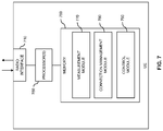
- FIG. 7 illustrates exemplary structures of a UE which may be used to implement the above concepts.
- the illustrated structures may be used to implement the above-described functionalities of the UE 50 .
- the UE includes a radio interface 710 which may be used for establishing a connection to a wireless communication network.
- the UE includes one or more processor(s) 750 coupled to the interfaces 710 and 720 , and a memory 760 coupled to the processor(s) 750 .
- the memory 760 may include a ROM, e.g., a flash ROM, a RAM, e.g., a DRAM or SRAM, a mass storage, e.g., a hard disk or solid state disk, or the like.
- the memory 760 includes suitably configured program code modules to be executed by the processor(s) 750 so as to implement the functionalities as described in connection with the method of FIG. 5 , in particular functionalities as explained above for the UE 50 .
- the program code modules in the memory 760 may include a measurement module 770 so as to implement the above-described functionalities of performing measurements for triggering the switching or selecting a target access point among multiple candidates. Further, the program code modules in the memory 760 may include a connection management module 780 so as to implement the above-mentioned functionalities of maintaining the connection between the UE and the wireless communication network, selecting a target access point, and performing the switching of the connection as authorized by the switching authorization message. Still further, the memory 760 may include a control module 790 so as to implement general control functionalities, such as control of the radio interface, processing control messages, or the like.
- the structures as illustrated in FIG. 7 are merely schematic and that the UE may actually include further components which, for the sake of clarity, have not been illustrated, e.g., further interfaces or further processors.
- the memory 760 may include further types of program code modules, which have not been illustrated, e.g., program code modules for implementing known functionalities of a UE.
- a computer program may be provided for implementing functionalities of the UE, e.g., in the form of a physical medium storing the program code modules to be stored in the memory 760 or by making such program code available for download.
- the concepts as described above may be used for efficiently managing the connection of the UE to the wireless communication network.
- the UE by authorizing the UE to autonomously switch the connection to one or more from a plurality of target access points, it becomes possible to perform the connection switching even if the radio link between the UE and the current serving access point of the UE fails.
Landscapes
- Engineering & Computer Science (AREA)
- Computer Networks & Wireless Communication (AREA)
- Signal Processing (AREA)
- Mobile Radio Communication Systems (AREA)
Applications Claiming Priority (1)
| Application Number | Priority Date | Filing Date | Title |
|---|---|---|---|
| PCT/CN2014/071844 WO2015113305A1 (en) | 2014-01-30 | 2014-01-30 | Autonomous connection switching in a wireless communication network |
Related Parent Applications (1)
| Application Number | Title | Priority Date | Filing Date |
|---|---|---|---|
| PCT/CN2014/071844 A-371-Of-International WO2015113305A1 (en) | 2014-01-30 | 2014-01-30 | Autonomous connection switching in a wireless communication network |
Related Child Applications (1)
| Application Number | Title | Priority Date | Filing Date |
|---|---|---|---|
| US17/194,440 Continuation US20210195494A1 (en) | 2014-01-30 | 2021-03-08 | Autonomous Connection Switching in a Wireless Communication Network |
Publications (2)
| Publication Number | Publication Date |
|---|---|
| US20170238228A1 US20170238228A1 (en) | 2017-08-17 |
| US10945181B2 true US10945181B2 (en) | 2021-03-09 |
Family
ID=53756195
Family Applications (2)
| Application Number | Title | Priority Date | Filing Date |
|---|---|---|---|
| US15/114,163 Active US10945181B2 (en) | 2014-01-30 | 2014-01-30 | Autonomous connection switching in a wireless communication network |
| US17/194,440 Pending US20210195494A1 (en) | 2014-01-30 | 2021-03-08 | Autonomous Connection Switching in a Wireless Communication Network |
Family Applications After (1)
| Application Number | Title | Priority Date | Filing Date |
|---|---|---|---|
| US17/194,440 Pending US20210195494A1 (en) | 2014-01-30 | 2021-03-08 | Autonomous Connection Switching in a Wireless Communication Network |
Country Status (17)
| Country | Link |
|---|---|
| US (2) | US10945181B2 (pl) |
| EP (3) | EP4366383A2 (pl) |
| JP (1) | JP6471168B2 (pl) |
| KR (1) | KR101889386B1 (pl) |
| CN (2) | CN111586776B (pl) |
| AU (2) | AU2014381181A1 (pl) |
| CA (1) | CA2938323C (pl) |
| DK (1) | DK3100512T3 (pl) |
| ES (1) | ES2729845T3 (pl) |
| HU (1) | HUE043489T2 (pl) |
| IL (1) | IL246724B (pl) |
| MX (1) | MX364018B (pl) |
| MY (1) | MY189910A (pl) |
| PL (1) | PL3100512T3 (pl) |
| RU (1) | RU2679415C2 (pl) |
| SG (1) | SG11201605771PA (pl) |
| WO (1) | WO2015113305A1 (pl) |
Families Citing this family (22)
| Publication number | Priority date | Publication date | Assignee | Title |
|---|---|---|---|---|
| US10945181B2 (en) | 2014-01-30 | 2021-03-09 | Telefonaktiebolaget Lm Ericsson (Publ) | Autonomous connection switching in a wireless communication network |
| US9980159B2 (en) * | 2014-09-26 | 2018-05-22 | Mediatek Inc. | RRC re-establishment on secondary eNodeB for dual connectivity |
| WO2017028897A1 (en) | 2015-08-17 | 2017-02-23 | Telefonaktiebolaget Lm Ericsson (Publ) | Multi-cell registered radio connection in cellular network |
| CN108370516B (zh) * | 2015-11-16 | 2021-01-05 | 华为技术有限公司 | 一种小区测量报告的方法及用户设备 |
| CN107295580A (zh) | 2016-03-30 | 2017-10-24 | 中兴通讯股份有限公司 | 接入点切换方法及装置 |
| CN113965968B (zh) | 2017-01-16 | 2024-03-19 | 瑞典爱立信有限公司 | 用于无线通信系统中的链路切换的方法、无线通信设备及网络节点 |
| US11064401B2 (en) * | 2017-04-01 | 2021-07-13 | Samsung Electronics Co., Ltd. | Random access method, network node and user equipment |
| CN114980231B (zh) * | 2017-04-05 | 2023-12-12 | 高通股份有限公司 | 在新无线电中的用户设备自主服务小区选择 |
| CN110999390B (zh) | 2017-06-15 | 2022-11-01 | Lg电子株式会社 | 在无线通信系统中执行切换过程的方法及其装置 |
| JP7034682B2 (ja) * | 2017-11-27 | 2022-03-14 | キヤノン株式会社 | 通信装置、通信装置の制御方法、プログラム |
| EP3738344A4 (en) * | 2018-01-10 | 2021-09-01 | Lenovo (Beijing) Limited | SELECTION OF A BASE UNIT IN RESPONSE TO A TRIGGERED FORWARDING CONDITION |
| CN112534874B (zh) * | 2018-08-17 | 2024-04-19 | 瑞典爱立信有限公司 | 用于处置链路转换的第一网络节点、无线装置以及由此执行的方法 |
| US10771147B2 (en) * | 2018-08-17 | 2020-09-08 | Hughes Network Systems Llc | Satellite communication system for diversity gateway switching and satellite communication method for diversity gateway switching |
| CN109104749B (zh) * | 2018-08-27 | 2022-06-07 | 创新维度科技(北京)有限公司 | 一种移动性切换控制方法、装置和存储介质 |
| WO2020057732A1 (en) * | 2018-09-18 | 2020-03-26 | Nokia Technologies Oy | Communication connection control using conditional handover |
| JP7097797B2 (ja) * | 2018-11-19 | 2022-07-08 | テレフオンアクチーボラゲット エルエム エリクソン(パブル) | 無線通信ネットワークにおける自動接続切り替え |
| JP2020098990A (ja) | 2018-12-18 | 2020-06-25 | 村田機械株式会社 | 無線通信機器、無線通信方法、及び繊維機械操業支援システム |
| US11310715B2 (en) * | 2019-02-26 | 2022-04-19 | Lg Electronics Inc. | Relaxation of mobility condition based on serving cell quality |
| WO2020175906A1 (en) * | 2019-02-26 | 2020-09-03 | Lg Electronics Inc. | Mobility condition change based on serving cell quality and connection release |
| US11956690B2 (en) | 2020-07-24 | 2024-04-09 | Asustek Computer Inc. | Method and apparatus for mobility procedure in a wireless communication system |
| US11678208B2 (en) | 2021-04-08 | 2023-06-13 | Cisco Technology, Inc. | Failure prediction signaling and cognitive user migration |
| WO2023056580A1 (en) * | 2021-10-06 | 2023-04-13 | Qualcomm Incorporated | Monitoring of messages that indicate switching between machine learning (ml) model groups |
Citations (29)
| Publication number | Priority date | Publication date | Assignee | Title |
|---|---|---|---|---|
| US20050026619A1 (en) * | 2003-07-31 | 2005-02-03 | Anjali Jha | System of and method for using position, velocity, or direction of motion estimates to support handover decisions |
| US20050250498A1 (en) * | 2004-05-07 | 2005-11-10 | Samsung Electronics Co., Ltd. | System and method for performing a fast handover in a broadband wireless access communication system |
| US20070086387A1 (en) | 2005-10-17 | 2007-04-19 | Samsung Electronics Co., Ltd. | Apparatus and method for handover in wireless access communication system |
| US20070293224A1 (en) | 2006-06-20 | 2007-12-20 | Interdigital Technology Corporation | Methods and system for performing handover in a wireless communication system |
| US20080318576A1 (en) | 2007-06-20 | 2008-12-25 | Tricci So | Handover Between Wireless Cellular Network and Private Network in Wireless Communications |
| CN101374326A (zh) | 2007-08-23 | 2009-02-25 | 大唐移动通信设备有限公司 | 一种用户终端参与切换决定的切换方法及其实现设备 |
| WO2009096883A1 (en) | 2008-01-18 | 2009-08-06 | Telefonaktiebolaget L M Ericsson (Publ) | Method and apparatus for radio link failure recovery in a telecommunication system |
| US20100173626A1 (en) | 2009-01-06 | 2010-07-08 | Qualcomm Incorporated | Adaptation of handover parameters |
| WO2010109591A1 (ja) | 2009-03-24 | 2010-09-30 | 富士通株式会社 | 基地局装置、移動端末、通信システムおよびその制御方法 |
| WO2010143428A1 (ja) | 2009-06-12 | 2010-12-16 | パナソニック株式会社 | 基地局制御装置および携帯端末 |
| US20100330993A1 (en) * | 2009-06-25 | 2010-12-30 | Mamadou Kone | Method of Initiating Handover Pre-preparation and Related Communication Device |
| WO2011014655A2 (en) | 2009-07-29 | 2011-02-03 | Panelclaw, Inc. | Ground mounted solar module integration system |
| WO2011024655A1 (ja) | 2009-08-26 | 2011-03-03 | シャープ株式会社 | 無線通信システムおよびハンドオーバー方法 |
| WO2011032499A1 (zh) | 2009-09-16 | 2011-03-24 | 华为技术有限公司 | 一种接入点切换方法及装置 |
| KR20120058120A (ko) | 2010-11-29 | 2012-06-07 | 주식회사 케이티 | 무선 네트워크에서 서버 기반 핸드오버 방법 및 이를 지원하는 장치 |
| CN102857983A (zh) | 2011-06-30 | 2013-01-02 | 中兴通讯股份有限公司 | 一种集群系统中听用户切换方法、网络侧和终端 |
| US20130183971A1 (en) * | 2011-08-11 | 2013-07-18 | Interdigital Patent Holdings, Inc. | Systems And/Or Methods For Providing Relay Mobility |
| WO2013177778A1 (en) | 2012-05-31 | 2013-12-05 | Nokia Corporation | Method, apparatus and computer program product for autonomous cell change by ue in network |
| US20140023045A1 (en) * | 2011-04-27 | 2014-01-23 | Fujitsu Limited | Enhancement to multiple handover preparation |
| EP2696624A1 (en) | 2012-08-07 | 2014-02-12 | Nokia Solutions and Networks Oy | Control mechanism for autonomous mobility of terminal device |
| US20140045494A1 (en) * | 2012-08-07 | 2014-02-13 | Nokia Siemens Networks Oy | Control Mechanism for Autonomous Mobility of Terminal Device |
| US20150079991A1 (en) * | 2011-09-12 | 2015-03-19 | Nokia Corporation | Method and apparatus for mobile terminal connected mode mobility |
| US20150304921A1 (en) * | 2012-12-28 | 2015-10-22 | Broadcom Corporation | Methods, devices, and computer program products improving mobile communication |
| US20150373596A1 (en) * | 2013-02-22 | 2015-12-24 | Intel IP Corporation | Improved handover with ping pong avoidance in a wireless network |
| US20160021585A1 (en) * | 2013-04-04 | 2016-01-21 | Nokia Solutions And Networks Oy | Avoiding Secondary Cell Configuration for High Speed User Equipment |
| US20160302127A1 (en) * | 2013-10-01 | 2016-10-13 | Samsung Electronics Co., Ltd. | Method and apparatus for controlling handover in mobile communication system |
| US20160337065A1 (en) * | 2014-01-15 | 2016-11-17 | Sharp Kabushiki Kaisha | Terminal device, base station apparatus, and integrated circuit |
| US20170238228A1 (en) | 2014-01-30 | 2017-08-17 | Telefonaktiebolaget Lm Ericsson (Publ) | Autonomous Connection Switching in a Wireless Communication Network |
| US9781635B2 (en) * | 2013-09-25 | 2017-10-03 | Alcatel Lucent | Base station providing handover among small cells |
Family Cites Families (5)
| Publication number | Priority date | Publication date | Assignee | Title |
|---|---|---|---|---|
| EP2026620B1 (en) * | 2007-08-14 | 2012-06-27 | Alcatel Lucent | Handover method and apparatus in a wireless telecommunications network |
| US9521565B2 (en) * | 2008-11-17 | 2016-12-13 | Qualcomm Incorporated | Declaring radio link failure based on target-specific threshold |
| US9155014B2 (en) * | 2008-11-17 | 2015-10-06 | Qualcomm Incorporated | Conditional access terminal initiation of delayed handover |
| US20140120921A1 (en) * | 2011-06-21 | 2014-05-01 | Nokia Corporation | Methods, apparatuses and computer program products for providing an optimized handover preparation and execution operation |
| CN103298051B (zh) * | 2012-02-24 | 2015-12-09 | 华为技术有限公司 | 一种切换方法及相关用户设备、系统 |
-
2014
- 2014-01-30 US US15/114,163 patent/US10945181B2/en active Active
- 2014-01-30 KR KR1020167023870A patent/KR101889386B1/ko active IP Right Grant
- 2014-01-30 ES ES14881344T patent/ES2729845T3/es active Active
- 2014-01-30 SG SG11201605771PA patent/SG11201605771PA/en unknown
- 2014-01-30 EP EP24151881.0A patent/EP4366383A2/en active Pending
- 2014-01-30 MX MX2016009836A patent/MX364018B/es active IP Right Grant
- 2014-01-30 EP EP19168705.2A patent/EP3565310B1/en active Active
- 2014-01-30 HU HUE14881344A patent/HUE043489T2/hu unknown
- 2014-01-30 CN CN202010075079.XA patent/CN111586776B/zh active Active
- 2014-01-30 CA CA2938323A patent/CA2938323C/en active Active
- 2014-01-30 EP EP14881344.7A patent/EP3100512B1/en active Active
- 2014-01-30 CN CN201480077808.8A patent/CN106537985B/zh active Active
- 2014-01-30 JP JP2016548359A patent/JP6471168B2/ja active Active
- 2014-01-30 WO PCT/CN2014/071844 patent/WO2015113305A1/en active Application Filing
- 2014-01-30 PL PL14881344T patent/PL3100512T3/pl unknown
- 2014-01-30 DK DK14881344.7T patent/DK3100512T3/da active
- 2014-01-30 RU RU2016135065A patent/RU2679415C2/ru active
- 2014-01-30 AU AU2014381181A patent/AU2014381181A1/en not_active Abandoned
- 2014-01-30 MY MYPI2016702750A patent/MY189910A/en unknown
-
2016
- 2016-07-11 IL IL246724A patent/IL246724B/en active IP Right Grant
-
2018
- 2018-03-02 AU AU2018201541A patent/AU2018201541B2/en active Active
-
2021
- 2021-03-08 US US17/194,440 patent/US20210195494A1/en active Pending
Patent Citations (40)
| Publication number | Priority date | Publication date | Assignee | Title |
|---|---|---|---|---|
| US20050026619A1 (en) * | 2003-07-31 | 2005-02-03 | Anjali Jha | System of and method for using position, velocity, or direction of motion estimates to support handover decisions |
| US7593731B2 (en) | 2004-05-07 | 2009-09-22 | Samsung Electronics Co., Ltd | System and method for performing a fast handover in a broadband wireless access communication system |
| US20050250498A1 (en) * | 2004-05-07 | 2005-11-10 | Samsung Electronics Co., Ltd. | System and method for performing a fast handover in a broadband wireless access communication system |
| CN1951035A (zh) | 2004-05-07 | 2007-04-18 | 三星电子株式会社 | 在宽带无线接入通信系统中执行快速移交的系统和方法 |
| JP2007536784A (ja) | 2004-05-07 | 2007-12-13 | サムスン エレクトロニクス カンパニー リミテッド | 広帯域無線接続通信システムにおける高速のハンドオーバーを遂行するためのシステム及び方法 |
| US7920868B2 (en) | 2004-05-07 | 2011-04-05 | Samsung Electronics Co., Ltd. | System and method for performing a fast handover in a broadband wireless access communication system |
| US20070086387A1 (en) | 2005-10-17 | 2007-04-19 | Samsung Electronics Co., Ltd. | Apparatus and method for handover in wireless access communication system |
| CN101014183A (zh) | 2005-10-17 | 2007-08-08 | 三星电子株式会社 | 无线接入通信系统中用于切换的设备和方法 |
| US20070293224A1 (en) | 2006-06-20 | 2007-12-20 | Interdigital Technology Corporation | Methods and system for performing handover in a wireless communication system |
| JP2010531124A (ja) | 2007-06-20 | 2010-09-16 | ゼットティーイー(ユーエスエー)インコーポレーテッド | 無線通信における無線セルラネットワークとプライベートネットワークとの間のハンドオーバ |
| US20080318576A1 (en) | 2007-06-20 | 2008-12-25 | Tricci So | Handover Between Wireless Cellular Network and Private Network in Wireless Communications |
| CN101374326A (zh) | 2007-08-23 | 2009-02-25 | 大唐移动通信设备有限公司 | 一种用户终端参与切换决定的切换方法及其实现设备 |
| WO2009096883A1 (en) | 2008-01-18 | 2009-08-06 | Telefonaktiebolaget L M Ericsson (Publ) | Method and apparatus for radio link failure recovery in a telecommunication system |
| US20100173626A1 (en) | 2009-01-06 | 2010-07-08 | Qualcomm Incorporated | Adaptation of handover parameters |
| JP2012514949A (ja) | 2009-01-06 | 2012-06-28 | クゥアルコム・インコーポレイテッド | ハンドオーバ・パラメータの適応 |
| US20110299505A1 (en) * | 2009-03-24 | 2011-12-08 | Fujitsu Limited | Base station device, mobile terminal, communication system, and method of controlling said communication system |
| WO2010109591A1 (ja) | 2009-03-24 | 2010-09-30 | 富士通株式会社 | 基地局装置、移動端末、通信システムおよびその制御方法 |
| WO2010143428A1 (ja) | 2009-06-12 | 2010-12-16 | パナソニック株式会社 | 基地局制御装置および携帯端末 |
| US20120088505A1 (en) | 2009-06-12 | 2012-04-12 | Panasonic Corporation | Base station controller and mobile terminal |
| US20100330993A1 (en) * | 2009-06-25 | 2010-12-30 | Mamadou Kone | Method of Initiating Handover Pre-preparation and Related Communication Device |
| WO2011014655A2 (en) | 2009-07-29 | 2011-02-03 | Panelclaw, Inc. | Ground mounted solar module integration system |
| WO2011024655A1 (ja) | 2009-08-26 | 2011-03-03 | シャープ株式会社 | 無線通信システムおよびハンドオーバー方法 |
| US20120165065A1 (en) | 2009-08-26 | 2012-06-28 | Shinichi Sawada | Wireless communication system and handover method |
| WO2011032499A1 (zh) | 2009-09-16 | 2011-03-24 | 华为技术有限公司 | 一种接入点切换方法及装置 |
| KR20120058120A (ko) | 2010-11-29 | 2012-06-07 | 주식회사 케이티 | 무선 네트워크에서 서버 기반 핸드오버 방법 및 이를 지원하는 장치 |
| US20140023045A1 (en) * | 2011-04-27 | 2014-01-23 | Fujitsu Limited | Enhancement to multiple handover preparation |
| CN102857983A (zh) | 2011-06-30 | 2013-01-02 | 中兴通讯股份有限公司 | 一种集群系统中听用户切换方法、网络侧和终端 |
| US20130183971A1 (en) * | 2011-08-11 | 2013-07-18 | Interdigital Patent Holdings, Inc. | Systems And/Or Methods For Providing Relay Mobility |
| US20150079991A1 (en) * | 2011-09-12 | 2015-03-19 | Nokia Corporation | Method and apparatus for mobile terminal connected mode mobility |
| WO2013177778A1 (en) | 2012-05-31 | 2013-12-05 | Nokia Corporation | Method, apparatus and computer program product for autonomous cell change by ue in network |
| US20150133121A1 (en) * | 2012-05-31 | 2015-05-14 | Nokia Corporation | Method, apparatus and computer program product for autonomous cell change by ue in network |
| EP2696624A1 (en) | 2012-08-07 | 2014-02-12 | Nokia Solutions and Networks Oy | Control mechanism for autonomous mobility of terminal device |
| US20140045494A1 (en) * | 2012-08-07 | 2014-02-13 | Nokia Siemens Networks Oy | Control Mechanism for Autonomous Mobility of Terminal Device |
| US20150304921A1 (en) * | 2012-12-28 | 2015-10-22 | Broadcom Corporation | Methods, devices, and computer program products improving mobile communication |
| US20150373596A1 (en) * | 2013-02-22 | 2015-12-24 | Intel IP Corporation | Improved handover with ping pong avoidance in a wireless network |
| US20160021585A1 (en) * | 2013-04-04 | 2016-01-21 | Nokia Solutions And Networks Oy | Avoiding Secondary Cell Configuration for High Speed User Equipment |
| US9781635B2 (en) * | 2013-09-25 | 2017-10-03 | Alcatel Lucent | Base station providing handover among small cells |
| US20160302127A1 (en) * | 2013-10-01 | 2016-10-13 | Samsung Electronics Co., Ltd. | Method and apparatus for controlling handover in mobile communication system |
| US20160337065A1 (en) * | 2014-01-15 | 2016-11-17 | Sharp Kabushiki Kaisha | Terminal device, base station apparatus, and integrated circuit |
| US20170238228A1 (en) | 2014-01-30 | 2017-08-17 | Telefonaktiebolaget Lm Ericsson (Publ) | Autonomous Connection Switching in a Wireless Communication Network |
Non-Patent Citations (5)
| Title |
|---|
| 3rd Generation Partnership Project, "3rd Generation Partnership Project; Technical Specification Group Radio Access Network; Evolved Universal Terrestrial Radio Access (E-UTRA); Radio Resource Control (RRC); Protocol specification (Release 12)", Technical Specification, 3GPP TS 36.331 V12.0.0, Dec. 1, 2013, pp. 1-349, 3GPP, France. |
| Baldemair, R. et al., "Future Wireless Communications", IEEE 77th Vehicular Technology Conference, Jun. 2, 2013, pp. 1-5. |
| Ericsson, "5G Radio Access", Ericsson white paper, Jun. 1, 2013, pp. 1-9. |
| ETRI, "Early HO CMD with Ping-Pang Avoidance, further information", 3GPP TSG-RAN WG2 #84,San Francisco, USA, Nov. 11, 2013, pp. 1-10, R2-134177, 3GPP. |
| NSN et al., "Autonomous SCell Management for Dual Connectivity Cases", 3GPP TSG-RAN WG2 Meeting #83, Aug. 19-23, 2013, pp. 1-4, Barcelona, Spain, R2-132339. |
Also Published As
Similar Documents
| Publication | Publication Date | Title |
|---|---|---|
| US20210195494A1 (en) | Autonomous Connection Switching in a Wireless Communication Network | |
| CN104137609B (zh) | 蜂窝式无线通信系统中的切换方法 | |
| US9622139B2 (en) | Method for improving handover performance in a cellular wireless communication system | |
| KR101950666B1 (ko) | 통신 시스템에서의 연결 재수립을 위한 방법 및 구조 | |
| EP2939467B1 (en) | Intelligent irat handover requests | |
| BR112012020879B1 (pt) | Detecção de falha de link de rádio (rlf) para recuperação | |
| EP2288201B1 (en) | UE measurements for hot spot detection | |
| US11159994B2 (en) | Uplink signal based handover control, handover cancellation and handover expiration | |
| US20180139673A1 (en) | Methods and Apparatus for Controlling Mobility in a Wireless Network | |
| EP3449581B1 (en) | Shaping of transmission beams | |
| JP7097797B2 (ja) | 無線通信ネットワークにおける自動接続切り替え | |
| BR112016017095B1 (pt) | Método de administrar uma conexão entre um equipamento de usuário e uma rede de comunicação sem fios, ponto de acesso, equipamento de usuário, e, meio de armazenamento não transitório |
Legal Events
| Date | Code | Title | Description |
|---|---|---|---|
| AS | Assignment |
Owner name: TELEFONAKTIEBOLAGET L M ERICSSON (PUBL), SWEDEN Free format text: ASSIGNMENT OF ASSIGNORS INTEREST;ASSIGNORS:LIU, JINHUA;ZHANG, ZHAN;REEL/FRAME:039257/0743 Effective date: 20140219 Owner name: TELEFONAKTIEBOLAGET LM ERICSSON (PUBL), SWEDEN Free format text: CHANGE OF NAME;ASSIGNOR:TELEFONAKTIEBOLAGET L M ERICSSON (PUBL);REEL/FRAME:039465/0625 Effective date: 20151119 |
|
| STPP | Information on status: patent application and granting procedure in general |
Free format text: NON FINAL ACTION MAILED |
|
| STPP | Information on status: patent application and granting procedure in general |
Free format text: RESPONSE TO NON-FINAL OFFICE ACTION ENTERED AND FORWARDED TO EXAMINER |
|
| STPP | Information on status: patent application and granting procedure in general |
Free format text: FINAL REJECTION MAILED |
|
| STPP | Information on status: patent application and granting procedure in general |
Free format text: ADVISORY ACTION MAILED |
|
| STPP | Information on status: patent application and granting procedure in general |
Free format text: DOCKETED NEW CASE - READY FOR EXAMINATION |
|
| STPP | Information on status: patent application and granting procedure in general |
Free format text: NON FINAL ACTION MAILED |
|
| STPP | Information on status: patent application and granting procedure in general |
Free format text: RESPONSE AFTER FINAL ACTION FORWARDED TO EXAMINER |
|
| STPP | Information on status: patent application and granting procedure in general |
Free format text: NOTICE OF ALLOWANCE MAILED -- APPLICATION RECEIVED IN OFFICE OF PUBLICATIONS |
|
| STCF | Information on status: patent grant |
Free format text: PATENTED CASE |
|
| CC | Certificate of correction |