US10940887B2 - Vehicle control apparatus and control method thereof - Google Patents
Vehicle control apparatus and control method thereof Download PDFInfo
- Publication number
- US10940887B2 US10940887B2 US15/963,086 US201815963086A US10940887B2 US 10940887 B2 US10940887 B2 US 10940887B2 US 201815963086 A US201815963086 A US 201815963086A US 10940887 B2 US10940887 B2 US 10940887B2
- Authority
- US
- United States
- Prior art keywords
- current
- information
- trailer
- esc
- vehicle control
- Prior art date
- Legal status (The legal status is an assumption and is not a legal conclusion. Google has not performed a legal analysis and makes no representation as to the accuracy of the status listed.)
- Active, expires
Links
Images


Classifications
-
- B—PERFORMING OPERATIONS; TRANSPORTING
- B60—VEHICLES IN GENERAL
- B60D—VEHICLE CONNECTIONS
- B60D1/00—Traction couplings; Hitches; Draw-gear; Towing devices
- B60D1/58—Auxiliary devices
- B60D1/62—Auxiliary devices involving supply lines, electric circuits or the like
-
- B—PERFORMING OPERATIONS; TRANSPORTING
- B62—LAND VEHICLES FOR TRAVELLING OTHERWISE THAN ON RAILS
- B62D—MOTOR VEHICLES; TRAILERS
- B62D13/00—Steering specially adapted for trailers
- B62D13/005—Steering specially adapted for trailers operated from tractor steering system
-
- B—PERFORMING OPERATIONS; TRANSPORTING
- B60—VEHICLES IN GENERAL
- B60W—CONJOINT CONTROL OF VEHICLE SUB-UNITS OF DIFFERENT TYPE OR DIFFERENT FUNCTION; CONTROL SYSTEMS SPECIALLY ADAPTED FOR HYBRID VEHICLES; ROAD VEHICLE DRIVE CONTROL SYSTEMS FOR PURPOSES NOT RELATED TO THE CONTROL OF A PARTICULAR SUB-UNIT
- B60W30/00—Purposes of road vehicle drive control systems not related to the control of a particular sub-unit, e.g. of systems using conjoint control of vehicle sub-units
- B60W30/02—Control of vehicle driving stability
-
- B—PERFORMING OPERATIONS; TRANSPORTING
- B60—VEHICLES IN GENERAL
- B60D—VEHICLE CONNECTIONS
- B60D1/00—Traction couplings; Hitches; Draw-gear; Towing devices
- B60D1/24—Traction couplings; Hitches; Draw-gear; Towing devices characterised by arrangements for particular functions
-
- B—PERFORMING OPERATIONS; TRANSPORTING
- B60—VEHICLES IN GENERAL
- B60W—CONJOINT CONTROL OF VEHICLE SUB-UNITS OF DIFFERENT TYPE OR DIFFERENT FUNCTION; CONTROL SYSTEMS SPECIALLY ADAPTED FOR HYBRID VEHICLES; ROAD VEHICLE DRIVE CONTROL SYSTEMS FOR PURPOSES NOT RELATED TO THE CONTROL OF A PARTICULAR SUB-UNIT
- B60W10/00—Conjoint control of vehicle sub-units of different type or different function
- B60W10/18—Conjoint control of vehicle sub-units of different type or different function including control of braking systems
- B60W10/184—Conjoint control of vehicle sub-units of different type or different function including control of braking systems with wheel brakes
-
- B—PERFORMING OPERATIONS; TRANSPORTING
- B60—VEHICLES IN GENERAL
- B60W—CONJOINT CONTROL OF VEHICLE SUB-UNITS OF DIFFERENT TYPE OR DIFFERENT FUNCTION; CONTROL SYSTEMS SPECIALLY ADAPTED FOR HYBRID VEHICLES; ROAD VEHICLE DRIVE CONTROL SYSTEMS FOR PURPOSES NOT RELATED TO THE CONTROL OF A PARTICULAR SUB-UNIT
- B60W10/00—Conjoint control of vehicle sub-units of different type or different function
- B60W10/20—Conjoint control of vehicle sub-units of different type or different function including control of steering systems
-
- B—PERFORMING OPERATIONS; TRANSPORTING
- B60—VEHICLES IN GENERAL
- B60W—CONJOINT CONTROL OF VEHICLE SUB-UNITS OF DIFFERENT TYPE OR DIFFERENT FUNCTION; CONTROL SYSTEMS SPECIALLY ADAPTED FOR HYBRID VEHICLES; ROAD VEHICLE DRIVE CONTROL SYSTEMS FOR PURPOSES NOT RELATED TO THE CONTROL OF A PARTICULAR SUB-UNIT
- B60W30/00—Purposes of road vehicle drive control systems not related to the control of a particular sub-unit, e.g. of systems using conjoint control of vehicle sub-units
- B60W30/02—Control of vehicle driving stability
- B60W30/045—Improving turning performance
-
- B—PERFORMING OPERATIONS; TRANSPORTING
- B60—VEHICLES IN GENERAL
- B60W—CONJOINT CONTROL OF VEHICLE SUB-UNITS OF DIFFERENT TYPE OR DIFFERENT FUNCTION; CONTROL SYSTEMS SPECIALLY ADAPTED FOR HYBRID VEHICLES; ROAD VEHICLE DRIVE CONTROL SYSTEMS FOR PURPOSES NOT RELATED TO THE CONTROL OF A PARTICULAR SUB-UNIT
- B60W40/00—Estimation or calculation of non-directly measurable driving parameters for road vehicle drive control systems not related to the control of a particular sub unit, e.g. by using mathematical models
- B60W40/10—Estimation or calculation of non-directly measurable driving parameters for road vehicle drive control systems not related to the control of a particular sub unit, e.g. by using mathematical models related to vehicle motion
- B60W40/105—Speed
-
- B—PERFORMING OPERATIONS; TRANSPORTING
- B60—VEHICLES IN GENERAL
- B60W—CONJOINT CONTROL OF VEHICLE SUB-UNITS OF DIFFERENT TYPE OR DIFFERENT FUNCTION; CONTROL SYSTEMS SPECIALLY ADAPTED FOR HYBRID VEHICLES; ROAD VEHICLE DRIVE CONTROL SYSTEMS FOR PURPOSES NOT RELATED TO THE CONTROL OF A PARTICULAR SUB-UNIT
- B60W40/00—Estimation or calculation of non-directly measurable driving parameters for road vehicle drive control systems not related to the control of a particular sub unit, e.g. by using mathematical models
- B60W40/10—Estimation or calculation of non-directly measurable driving parameters for road vehicle drive control systems not related to the control of a particular sub unit, e.g. by using mathematical models related to vehicle motion
- B60W40/114—Yaw movement
-
- B—PERFORMING OPERATIONS; TRANSPORTING
- B62—LAND VEHICLES FOR TRAVELLING OTHERWISE THAN ON RAILS
- B62D—MOTOR VEHICLES; TRAILERS
- B62D15/00—Steering not otherwise provided for
- B62D15/02—Steering position indicators ; Steering position determination; Steering aids
- B62D15/021—Determination of steering angle
-
- B—PERFORMING OPERATIONS; TRANSPORTING
- B62—LAND VEHICLES FOR TRAVELLING OTHERWISE THAN ON RAILS
- B62D—MOTOR VEHICLES; TRAILERS
- B62D53/00—Tractor-trailer combinations; Road trains
-
- B—PERFORMING OPERATIONS; TRANSPORTING
- B62—LAND VEHICLES FOR TRAVELLING OTHERWISE THAN ON RAILS
- B62D—MOTOR VEHICLES; TRAILERS
- B62D6/00—Arrangements for automatically controlling steering depending on driving conditions sensed and responded to, e.g. control circuits
- B62D6/002—Arrangements for automatically controlling steering depending on driving conditions sensed and responded to, e.g. control circuits computing target steering angles for front or rear wheels
- B62D6/003—Arrangements for automatically controlling steering depending on driving conditions sensed and responded to, e.g. control circuits computing target steering angles for front or rear wheels in order to control vehicle yaw movement, i.e. around a vertical axis
-
- B—PERFORMING OPERATIONS; TRANSPORTING
- B60—VEHICLES IN GENERAL
- B60W—CONJOINT CONTROL OF VEHICLE SUB-UNITS OF DIFFERENT TYPE OR DIFFERENT FUNCTION; CONTROL SYSTEMS SPECIALLY ADAPTED FOR HYBRID VEHICLES; ROAD VEHICLE DRIVE CONTROL SYSTEMS FOR PURPOSES NOT RELATED TO THE CONTROL OF A PARTICULAR SUB-UNIT
- B60W2300/00—Indexing codes relating to the type of vehicle
- B60W2300/14—Tractor-trailers, i.e. combinations of a towing vehicle and one or more towed vehicles, e.g. caravans; Road trains
- B60W2300/145—Semi-trailers
-
- B—PERFORMING OPERATIONS; TRANSPORTING
- B60—VEHICLES IN GENERAL
- B60W—CONJOINT CONTROL OF VEHICLE SUB-UNITS OF DIFFERENT TYPE OR DIFFERENT FUNCTION; CONTROL SYSTEMS SPECIALLY ADAPTED FOR HYBRID VEHICLES; ROAD VEHICLE DRIVE CONTROL SYSTEMS FOR PURPOSES NOT RELATED TO THE CONTROL OF A PARTICULAR SUB-UNIT
- B60W2510/00—Input parameters relating to a particular sub-units
- B60W2510/20—Steering systems
- B60W2510/202—Steering torque
-
- B—PERFORMING OPERATIONS; TRANSPORTING
- B60—VEHICLES IN GENERAL
- B60W—CONJOINT CONTROL OF VEHICLE SUB-UNITS OF DIFFERENT TYPE OR DIFFERENT FUNCTION; CONTROL SYSTEMS SPECIALLY ADAPTED FOR HYBRID VEHICLES; ROAD VEHICLE DRIVE CONTROL SYSTEMS FOR PURPOSES NOT RELATED TO THE CONTROL OF A PARTICULAR SUB-UNIT
- B60W2520/00—Input parameters relating to overall vehicle dynamics
- B60W2520/10—Longitudinal speed
-
- B—PERFORMING OPERATIONS; TRANSPORTING
- B60—VEHICLES IN GENERAL
- B60W—CONJOINT CONTROL OF VEHICLE SUB-UNITS OF DIFFERENT TYPE OR DIFFERENT FUNCTION; CONTROL SYSTEMS SPECIALLY ADAPTED FOR HYBRID VEHICLES; ROAD VEHICLE DRIVE CONTROL SYSTEMS FOR PURPOSES NOT RELATED TO THE CONTROL OF A PARTICULAR SUB-UNIT
- B60W2520/00—Input parameters relating to overall vehicle dynamics
- B60W2520/14—Yaw
-
- B—PERFORMING OPERATIONS; TRANSPORTING
- B60—VEHICLES IN GENERAL
- B60W—CONJOINT CONTROL OF VEHICLE SUB-UNITS OF DIFFERENT TYPE OR DIFFERENT FUNCTION; CONTROL SYSTEMS SPECIALLY ADAPTED FOR HYBRID VEHICLES; ROAD VEHICLE DRIVE CONTROL SYSTEMS FOR PURPOSES NOT RELATED TO THE CONTROL OF A PARTICULAR SUB-UNIT
- B60W2520/00—Input parameters relating to overall vehicle dynamics
- B60W2520/28—Wheel speed
-
- B—PERFORMING OPERATIONS; TRANSPORTING
- B60—VEHICLES IN GENERAL
- B60W—CONJOINT CONTROL OF VEHICLE SUB-UNITS OF DIFFERENT TYPE OR DIFFERENT FUNCTION; CONTROL SYSTEMS SPECIALLY ADAPTED FOR HYBRID VEHICLES; ROAD VEHICLE DRIVE CONTROL SYSTEMS FOR PURPOSES NOT RELATED TO THE CONTROL OF A PARTICULAR SUB-UNIT
- B60W2540/00—Input parameters relating to occupants
- B60W2540/18—Steering angle
-
- B—PERFORMING OPERATIONS; TRANSPORTING
- B60—VEHICLES IN GENERAL
- B60Y—INDEXING SCHEME RELATING TO ASPECTS CROSS-CUTTING VEHICLE TECHNOLOGY
- B60Y2200/00—Type of vehicle
- B60Y2200/10—Road Vehicles
- B60Y2200/14—Trucks; Load vehicles, Busses
- B60Y2200/148—Semi-trailers, articulated vehicles
Definitions
- the present disclosure relates to a vehicle control apparatus and a control method thereof.
- a conventional trailer is a vehicle without power that carries a load or a person by connecting to a towing vehicle.
- the automatic hitch ball device of the conventional trailer has a limitation in stably operating an ESC apparatus when the trailer is connected, and has a limitation in stabilizing the behavior of the trailer while stably operating the EPS apparatus in connecting the trailer.
- An aspect of the present disclosure is to provide a vehicle control apparatus and a control method thereof capable of stably operating an ESC apparatus when a trailer is connected.
- An aspect of the present disclosure is to provide a vehicle control apparatus and a control method thereof capable of stabilizing the behavior of a trailer while stably operating an EPS apparatus when a trailer is connected.
- An aspect of the present disclosure is to provide a vehicle control apparatus and a control method thereof capable of suppressing anxiety about a current operating state of an ESC apparatus to improve the reliability of the apparatus.
- An aspect of the present disclosure is to provide a vehicle control apparatus and a control method thereof capable of suppressing anxiety about a current state of a trailer to improve the reliability of the apparatus.
- a vehicle control apparatus including: a sensing unit that senses at least one of current trailer connection information, current trailer load information, current trailer traction information, and current trailer relative angle information; a determination unit that determines whether a trailer is in a mounted state by using the sensed current trailer connection information, and determines whether an ESC (Electronic Stability Control) is in an unstable operation state by using at least one of the sensed current trailer load information, current trailer traction information, and current trailer relative angle information when the trailer is in the mounted state; and a control unit that transmits a first compensation signal to an ESC apparatus to compensate the ESC apparatus in accordance with the set target ESC stable operation control information in order to operate the ESC apparatus in a stable operation state according to at least one of the sensed current trailer load information, current trailer traction information, and current trailer relative angle information when the ESC is in the unstable operation state.
- a sensing unit that senses at least one of current trailer connection information, current trailer load information, current trailer traction information, and current trailer relative angle information
- the sensing unit may further sense at least one of current vehicle speed information, current wheel speed information, current steering angle information, and current YAW/G information when the trailer is in the mounted state; the determination unit may further determine whether the ESC is in an unstable operation state by further using at least one of the sensed current vehicle speed information, current wheel speed information, current steering angle information, and current YAW/G information; and the control unit may further transmit the first compensation signal to the ESC apparatus to compensate the ESC apparatus in accordance with the set target ESC stable operation control information in order to operate the ESC apparatus in a stable operation state according to at least one of the sensed current vehicle speed information, current wheel speed information, current steering angle information, current YAW/G information, current trailer connection information, current trailer load information, current trailer traction information, and current trailer relative angle information when the ESC is in the unstable operation state.
- the sensing unit may further sense at least one of current steering angle information and current steering torque information when a first compensation completion signal is received from the ESC apparatus; the determination unit may further determine whether the behavior of the trailer is in an unstable operation state by further using at least one of the sensed current steering angle information and the current steering torque information; and the control unit may further transmit a second compensation signal to an EPS apparatus to compensate the EPS apparatus in accordance with the set target EPS stable operation control information in order to stabilize the behavior of the trailer by a steering operation of the EPS apparatus according to at least one of the sensed current steering angle information and current steering torque information corresponding to the compensated target ESC stable operation control information when the behavior of the trailer is in the unstable operation state.
- the vehicle control apparatus may further include an identification unit that identifies that the current ESC apparatus operates unstably when the ESC is in the unstable operation state.
- the vehicle control apparatus may further include an identification unit that identifies that the current ESC apparatus is stably compensated when compensating the ESC apparatus in accordance with the target ESC stable operation control information.
- the vehicle control apparatus may further include an identification unit that identifies that the current ESC apparatus has been stably compensated when a first compensation completion signal is received from the ESC apparatus.
- the vehicle control apparatus may further include an identification unit that identifies that the behavior of the current trailer is unstably operated when the behavior of the trailer is in the unstable operation state.
- the vehicle control apparatus may further include an identification unit that identifies that the behavior of the current trailer is stabilized when the EPS apparatus is compensated in accordance with the target EPS stable operation control information.
- the vehicle control apparatus may further include an identification unit that identifies that the behavior of the current trailer has been stably compensated when a second compensation completion signal is received from the EPS apparatus.
- a vehicle control method including: sensing current trailer connection information; determining whether a trailer is in a mounted state by using the sensed current trailer connection information; sensing at least one of current trailer load information, current trailer traction information, and current trailer relative angle information when the trailer is in the mounted state; determining whether an ESC (Electronic Stability Control) is in an unstable operation state by using at least one of the sensed current trailer load information, current trailer traction information, and current trailer relative angle information; and transmitting a first compensation signal to an ESC apparatus to compensate the ESC apparatus in accordance with the set target ESC stable operation control information in order to operate the ESC apparatus in a stable operation state according to at least one of the sensed current trailer load information, current trailer traction information, and current trailer relative angle information when the ESC is in the unstable operation state.
- ESC Electronic Stability Control
- the vehicle control method may further include: sensing at least one of current vehicle speed information, current wheel speed information, current steering angle information, and current YAW/G information when the trailer is in the mounted state; determining whether the ESC is in an unstable operation state by further using at least one of the sensed current vehicle speed information, current wheel speed information, current steering angle information, and current YAW/G information; and transmitting the first compensation signal to the ESC apparatus to compensate the ESC apparatus in accordance with the set target ESC stable operation control information in order to operate the ESC apparatus in a stable operation state according to at least one of the sensed current vehicle speed information, current wheel speed information, current steering angle information, current YAW/G information, current trailer connection information, current trailer load information, current trailer traction information, and current trailer relative angle information when the ESC is in the unstable operation state.
- the vehicle control method may further include: sensing at least one of current steering angle information and current steering torque information when a first compensation completion signal is received from the ESC apparatus; determining whether the behavior of the trailer is in an unstable operation state by further using at least one of the sensed current steering angle information and the current steering torque information; and transmitting a second compensation signal to an EPS apparatus to compensate the EPS apparatus in accordance with the set target EPS stable operation control information in order to stabilize the behavior of the trailer by a steering operation of the EPS apparatus according to at least one of the sensed current steering angle information and current steering torque information corresponding to the compensated target ESC stable operation control information when the behavior of the trailer is in the unstable operation state.
- the vehicle control method may further include identifying that the current ESC apparatus operates unstably when the ESC is in the unstable operation state.
- the vehicle control method may further include identifying that the current ESC apparatus is stably compensated when compensating the ESC apparatus in accordance with the target ESC stable operation control information.
- the vehicle control method may further include identifying that the current ESC apparatus has been stably compensated when a first compensation completion signal is received from the ESC apparatus.
- the vehicle control method may further include identifying that the behavior of the current trailer is unstably operated when the behavior of the trailer is in the unstable operation state.
- the vehicle control method may further include identifying that the behavior of the current trailer is stabilized when the EPS apparatus is compensated in accordance with the target EPS stable operation control information.
- the vehicle control method may further include identifying that the behavior of the current trailer has been stably compensated when a second compensation completion signal is received from the EPS apparatus.
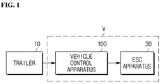
- FIG. 1 is a block diagram illustrating a state in which a vehicle control apparatus according to an embodiment of the present disclosure is connected to a trailer and an ESC apparatus;
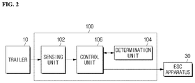
- FIG. 2 is a block diagram illustrating an example of the vehicle control apparatus shown in FIG. 1 ;
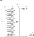
- FIG. 3 is a block diagram illustrating an example of a sensing unit shown in FIG. 2 ;
- FIG. 4 is a block diagram illustrating another example of a sensing unit shown in FIG. 2 ;
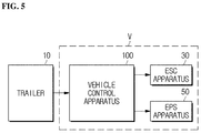
- FIG. 5 is a block diagram illustrating a state in which a vehicle control apparatus according to an embodiment of the present disclosure is connected to a trailer, an ESC apparatus and an EPS apparatus;
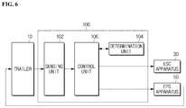
- FIG. 6 is a block diagram illustrating an example of the vehicle control apparatus shown in FIG. 5 ;
- FIG. 7 is a block diagram illustrating an example of a sensing unit shown in FIG. 6 ;
- FIG. 8 is a block diagram illustrating another example of a sensing unit shown in FIG. 6 ;
- FIG. 9 is a plan view for illustrating, as an example, a state in which a connector part, a load cell, and an angle sensor shown in FIGS. 3, 4, 7, and 8 are mounted on a vehicle and a trailer;
- FIG. 10 is a flowchart illustrating an example of a vehicle control method for a vehicle control apparatus according to an embodiment of the present disclosure
- FIG. 11 is a flowchart illustrating another example of a vehicle control method for a vehicle control apparatus according to an embodiment of the present disclosure
- FIG. 12 is a flowchart illustrating another example of a vehicle control method for a vehicle control apparatus according to an embodiment of the present disclosure
- FIG. 13 is a flowchart illustrating another example of a vehicle control method for a vehicle control apparatus according to an embodiment of the present disclosure
- FIG. 14 is a block diagram illustrating another example of a vehicle control apparatus according to an embodiment of the present disclosure.
- FIG. 15 is a flowchart illustrating another example of a vehicle control method for a vehicle control apparatus according to an embodiment of the present disclosure
- FIG. 16 is a flowchart illustrating another example of a vehicle control method for a vehicle control apparatus according to an embodiment of the present disclosure
- FIG. 17 is a flowchart illustrating another example of a vehicle control method for a vehicle control apparatus according to an embodiment of the present disclosure
- FIG. 18 is a block diagram illustrating another example of a vehicle control apparatus according to an embodiment of the present disclosure.
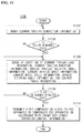
- FIG. 19 is a flowchart illustrating another example of a vehicle control method for a vehicle control apparatus according to an embodiment of the present disclosure.
- FIG. 20 is a flowchart illustrating another example of a vehicle control method for a vehicle control apparatus according to an embodiment of the present disclosure.
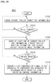
- FIG. 21 is a flowchart illustrating another example of a vehicle control method for a vehicle control apparatus according to an embodiment of the present disclosure.
- FIG. 1 is a block diagram illustrating a state in which a vehicle control apparatus according to an embodiment of the present disclosure is connected to a trailer and an ESC apparatus
- FIG. 2 is a block diagram illustrating an example of the vehicle control apparatus shown in FIG. 1 .
- FIG. 3 is a block diagram illustrating an example of the sensing unit shown in FIG. 2
- FIG. 4 is a block diagram illustrating another example of the sensing unit shown in FIG. 2 .
- FIG. 5 is a block diagram illustrating a state in which a vehicle control apparatus according to an embodiment of the present disclosure is connected to a trailer, an ESC apparatus and an EPS apparatus
- FIG. 6 is a block diagram illustrating an example of the vehicle control apparatus shown in FIG. 5 .
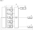
- FIG. 7 is a block diagram illustrating an example of a sensing unit shown in FIG. 6
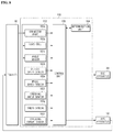
- FIG. 8 is a block diagram illustrating another example of a sensing unit shown in FIG. 6 .
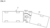
- FIG. 9 is a plan view for illustrating, as an example, a state in which a connector part, a load cell, and an angle sensor shown in FIGS. 3, 4, 7, and 8 are mounted on a vehicle and a trailer.
- a vehicle control apparatus 100 includes a sensing unit 102 , a determination unit 104 , and a control unit 106 .
- the sensing unit 102 senses at least one of current trailer connection information, current trailer load information, current trailer traction information, and current trailer relative angle information.
- the sensing unit 102 may include a connector part 102 a , a load cell 102 b , and an angle sensor 102 c.
- the connector part 102 a may sense current trailer connection information
- the load cell 102 b may sense current trailer load information and current trailer traction information
- the angle sensor 102 c may sense current trailer relative angle information.
- a connection sensing sensor 102 al of the connector part 102 a may be provided at one side of a vehicle V, and a connection cable 102 a 2 of the connector part 102 a may be provided at one end of a trailer 10 and may be connected to the connection sensing sensor 102 a 1 .
- the load cell 102 b may be provided at the other side of the vehicle V, and the angle sensor 102 c may be provided at a position where the vehicle V and the trailer 10 are connected.
- the determination unit 104 determines whether the trailer 10 is in a mounted state by using the current trailer connection information sensed by the sensing unit 102 according to the control of the control unit 106 which will be described later.
- the determination unit 104 determines whether or not an ESC (Electronic Stability Control) is in an unstable operation state according to the control of the control unit 106 by using at least one of the current trailer load information, the current trailer traction information, and the current trailer relative angle information which are sensed from the sensing unit 102 .
- ESC Electrical Stability Control
- the determination unit 104 determines whether or not the ESC is in an unstable operation state according to the control of the control unit 106 by using a TSC (Trailer Stability Control) using at least one of the current trailer load information, the current trailer traction information, and the current trailer relative angle information which are sensed from the sensing unit 102 .
- TSC Trailer Stability Control
- the determination unit 104 may determine whether the current trailer load information sensed by the sensing unit 102 is not the set target trailer load information according to the control of the control unit 106 .
- the determination unit 104 may determine whether the current trailer load value sensed by the sensing unit 102 is out of the set target trailer load value range according to the control of the control unit 106 .
- the determination unit 104 may determine whether the current trailer load value sensed by the sensing unit 102 is greater than 750 kg that is in the set target trailer load value range according to the control of the control unit 106 .
- the determination unit 104 may determine whether the current trailer traction information sensed by the sensing unit 102 is not the set target trailer traction information according to the control of the control unit 106 .
- the determination unit 104 may determine whether the current trailer traction force sensed by the sensing unit 102 is out of the set target trailer traction force range according to the control of the control unit 106 .
- the determination unit 104 may determine whether the current trailer traction force sensed by the sensing unit 102 is greater than 400 kgf that is in the set target trailer traction force range according to the control of the control unit 106 .
- the determination unit 104 may determine whether the current trailer relative angle information sensed by the sensing unit 102 is not the set target trailer relative angle information according to the control of the control unit 106 .
- the determination unit 104 may determine whether the current trailer relative angle value sensed by the sensing unit 102 is out of the set target trailer relative angle value range according to the control of the control unit 106 .
- the determination unit 104 may determine whether the current trailer relative angle value sensed by the sensing unit 102 is greater than 5 degrees that is in the set target trailer relative angle value range according to the control of the control unit 106 .
- the control unit 106 may transmit a first compensation signal to an ESC apparatus 30 to compensate the ESC apparatus 30 in accordance with the set target ESC stable operation control information in order to operate the ESC apparatus 30 in a stable operation state according to at least one of the current trailer load information, current trailer traction information, and current trailer relative angle information sensed by the sensing unit 102 .
- the sensing unit 102 of the vehicle control apparatus 100 may further sense at least one of current vehicle speed information, current wheel speed information, current steering angle information, and YAW/G information.
- the sensing unit 102 may include a vehicle speed sensor 102 d , a wheel speed sensor 102 e , a steering angle sensor 102 f , and an YAW/G sensor 102 g.
- the vehicle speed sensor 102 d may sense current vehicle speed information
- the wheel speed sensor 102 e may sense current wheel speed information
- the steering angle sensor 102 f may sense current steering angle information
- the YAW/G sensor 102 g may sense current YAW/G information.
- the determination unit 104 of the vehicle control apparatus 100 may further determine whether the ESC is in an unstable operation state according to the control of the control unit 106 by further using at least one of the current vehicle speed information, current wheel speed information, current steering angle information, and current YAW/G information which are sensed by the sensing unit 102 .
- the determination unit 104 may determine whether the current vehicle speed information sensed by the sensing unit 102 is not the set target vehicle speed information according to the control of the control unit 106 .
- the determination unit 104 may determine whether the current vehicle speed value sensed by the sensing unit 102 is out of the set target vehicle speed value range according to the control of the control unit 106 .
- the determination unit 104 may determine whether the current vehicle speed value sensed by the sensing unit 102 is greater than 60 kph that is in the set target vehicle speed value range according to the control of the control unit 106 .
- the determination unit 104 may determine whether the current wheel speed information sensed by the sensing unit 102 is not the set target wheel speed information according to the control of the control unit 106 .
- the determination unit 104 may determine whether the current wheel speed value sensed by the sensing unit 102 is out of the set target wheel speed value range according to the control of the control unit 106 .
- the determination unit 104 may determine whether the current wheel speed value sensed by the sensing unit 102 is greater than 60 kph that is in the set target wheel speed value range according to the control of the control unit 106 .
- the determination unit 104 may determine whether the current steering angle information sensed by the sensing unit 102 is not the set target steering angle information according to the control of the control unit 106 .
- the determination unit 104 may determine whether the current steering angle value sensed by the sensing unit 102 is out of the set target steering angle value range according to the control of the control unit 106 .
- the determination unit 104 may determine whether the current steering angle value sensed by the sensing unit 102 is greater than 15 degrees that is in the set target steering angle value range according to the control of the control unit 106 .
- the determination unit 104 may determine whether the current YAW/G information sensed by the sensing unit 102 is not the set target YAW/G information according to the control of the control unit 106 .
- the determination unit 104 may determine whether the current YAW/G value sensed by the sensing unit 102 is out of the set target YAW/G value range according to the control of the control unit 106 .
- the determination unit 104 may determine whether the current YAW/G value sensed by the sensing unit 102 is greater than 0.2 g that is in the set target YAW/G value range according to the control of the control unit 106 .
- the sensing unit 102 of the vehicle control apparatus 100 may further sense at least one of current steering angle information and current steering torque information.
- the sensing unit 102 may include the steering angle sensor 102 f and a steering torque sensor 102 h.
- the steering angle sensor 102 f may sense current steering angle information
- the steering torque sensor 102 h may sense current steering torque information.
- the determination unit 104 may further determine whether the behavior of the trailer 10 is in an unstable operation state by further using at least one of current steering angle information and current steering torque information according to the control of the control unit 106 .
- the determination unit 104 may determine whether the current steering angle information sensed by the sensing unit 102 is not the set target steering angle information according to the control of the control unit 106 .
- the determination unit 104 may determine whether the current steering angle value sensed by the sensing unit 102 is out of the set target steering angle value range according to the control of the control unit 106 .
- the determination unit 104 may determine whether the current steering angle value sensed by the sensing unit 102 is greater than 15 degrees that is in the set target steering angle value range according to the control of the control unit 106 .
- the determination unit 104 may determine whether the current steering torque information sensed by the sensing unit 102 is not the set target steering torque information according to the control of the control unit 106 .
- the determination unit 104 may determine whether the current steering torque value sensed by the sensing unit 102 is out of the set target steering torque value range according to the control of the control unit 106 .
- the determination unit 104 may determine whether the current steering torque value sensed by the sensing unit 102 is greater than 3 Nm that is in the set target steering torque value range according to the control of the control unit 106 .
- the control unit 106 may further transmit a second compensation signal to an EPS apparatus 50 to compensate the EPS apparatus 50 in accordance with the set target EPS stable operation control information in order to stabilize the behavior of the trailer 10 by a steering operation of the EPS apparatus 50 according to at least one of the current steering angle information and current steering torque information sensed by the sensing unit 102 corresponding to the compensated target ESC stable operation control information when the behavior of the trailer 10 is in the unstable operation state.
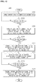
- FIG. 10 is a flowchart illustrating an example of a vehicle control method for a vehicle control apparatus according to an embodiment of the present disclosure
- FIG. 11 is a flowchart illustrating another example of a vehicle control method for a vehicle control apparatus according to an embodiment of the present disclosure.
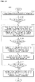
- FIG. 12 is a flowchart illustrating another example of a vehicle control method for a vehicle control apparatus according to an embodiment of the present disclosure
- FIG. 13 is a flowchart illustrating another example of a vehicle control method for a vehicle control apparatus according to an embodiment of the present disclosure.
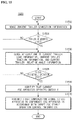
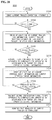
- vehicle control methods 1000 to 1300 for the vehicle control apparatus 00 may include first sensing steps (S 1002 to S 1302 ), first determination steps (S 1004 to S 1304 ), second sensing steps (S 1006 to S 1306 ), second determination steps (S 1008 to S 1308 ), and first compensation steps (S 1010 to S 1310 ), respectively.
- the determination unit 104 determines whether or not the ESC is in an unstable operation state in the second determination steps (S 1008 to S 1308 )
- whether the current trailer load information sensed by the sensing unit 102 ( FIGS. 2 to 4 and 6 to 8 ) is not the target trailer load information set in the determination unit 104 ( FIGS. 2 to 4 and 6 to 8 ) may be determined by the determination unit 104 ( FIGS. 2 to 4 and 6 to 8 ) according to the control of the control unit 106 ( FIGS. 2 to 4 and 6 to 8 ).
- the determination unit 104 determines whether or not the ESC is in an unstable operation state in the second determination steps (S 1008 to S 1308 )
- whether the current trailer traction information sensed by the sensing unit 102 ( FIGS. 2 to 4 and 6 to 8 ) is not the target trailer traction information set in the determination unit 104 ( FIGS. 2 to 4 and 6 to 8 ) may be determined by the determination unit 104 ( FIGS. 2 to 4 and 6 to 8 ) according to the control of the control unit 106 ( FIGS. 2 to 4 and 6 to 8 ).
- the determination unit 104 determines whether or not the ESC is in an unstable operation state in the second determination steps (S 1008 to S 1308 )
- whether the current trailer relative angle information sensed by the sensing unit 102 ( FIGS. 2 to 4 and 6 to 8 ) is not the target trailer relative angle information set in the determination unit 104 ( FIGS. 2 to 4 and 6 to 8 ) may be determined by the determination unit 104 ( FIGS. 2 to 4 and 6 to 8 ) according to the control of the control unit 106 ( FIGS. 2 to 4 and 6 to 8 ).
- a first compensation signal is transmitted to the ESC apparatus 30 ( FIGS. 2 to 4 and 6 to 8 ) by the control unit 106 ( FIGS. 2 to 4 and 6 to 8 ) to compensate the ESC apparatus 30 ( FIGS. 2 to 4 and 6 to 8 ) in accordance with the target ESC stable operation control information set in the control unit 106 ( FIGS. 2 to 4 and 6 to 8 ) in order to operate the ESC apparatus 30 ( FIGS. 2 to 4 and 6 to 8 ) in a stable operation state according to at least one of the current trailer load information, current trailer traction information, and current trailer relative angle information sensed by the sensing unit 102 ( FIGS. 2 to 4 and 6 to 8 ).
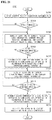
- the vehicle control methods ( 1100 and 1300 ) for the vehicle control apparatus 100 may include the second sensing steps (S 1106 and S 1306 ), the second determination steps (S 1108 and S 1308 ), and first compensation steps (S 1110 and S 1310 ), respectively.
- At least one of current vehicle speed information, current wheel speed information, current steering angle information, and current YAW/G information may further be sensed by the sensing unit 102 ( FIGS. 4 and 8 ).
- whether or not the ESC is in an unstable operation state may be determined by the determination unit 104 ( FIGS. 4 and 8 ) by further using at least one of the current vehicle speed information, current wheel speed information, current steering angle information, and current YAW/G information sensed by the sensing unit 102 ( FIGS. 4 and 8 ) according to the control of the control unit 106 ( FIGS. 4 and 8 ).
- the determination unit 104 determines whether or not the ESC is in an unstable operation state
- whether the current vehicle speed information sensed by the sensing unit 102 ( FIGS. 4 and 8 ) is not the target vehicle speed information set in the determination unit 104 ( FIGS. 4 and 8 ) may be determined by the determination unit 104 ( FIGS. 4 and 8 ) according to the control of the control unit 106 ( FIGS. 4 and 8 ).
- the determination unit 104 determines whether or not the ESC is in an unstable operation state
- whether the current wheel speed information sensed by the sensing unit 102 ( FIGS. 4 and 8 ) is not the target wheel speed information set in the determination unit 104 ( FIGS. 4 and 8 ) may be determined by the determination unit 104 ( FIGS. 4 and 8 ) according to the control of the control unit 106 ( FIGS. 4 and 8 ).
- the determination unit 104 determines whether or not the ESC is in an unstable operation state
- whether the current steering angle information sensed by the sensing unit 102 ( FIGS. 4 and 8 ) is not the target steering angle information set in the determination unit 104 ( FIGS. 4 and 8 ) may be determined by the determination unit 104 ( FIGS. 4 and 8 ) according to the control of the control unit 106 ( FIGS. 4 and 8 ).
- the determination unit 104 determines whether or not the ESC is in an unstable operation state
- whether the current YAW/G information sensed by the sensing unit 102 ( FIGS. 4 and 8 ) is not the target YAW/G information set in the determination unit 104 ( FIGS. 4 and 8 ) may be determined by the determination unit 104 ( FIGS. 4 and 8 ) according to the control of the control unit 106 ( FIGS. 4 and 8 ).
- the first compensation signal may be further transmitted to the ESC apparatus 30 ( FIGS. 4 and 8 ) by the control unit 106 ( FIGS. 4 and 8 ) to compensate the ESC apparatus 30 ( FIGS. 4 and 8 ) in accordance with the target ESC stable operation control information set in the control unit 106 ( FIGS. 4 and 8 ) in order to operate the ESC apparatus 30 ( FIGS. 4 and 8 ) in a stable operation state according to at least one of the current vehicle speed information, current wheel speed information, current steering angle information, and current YAW/G information sensed by the sensing unit 102 ( FIGS. 4 and 8 ).
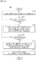
- the vehicle control methods ( 1200 and 1300 ) for the vehicle control apparatus 100 may include third sensing steps (S 1212 and S 1312 ), third determination steps (S 1214 and S 1314 ), and second compensation steps (S 1216 and S 1316 ), respectively.
- whether or not the behavior of the trailer is in an unstable operation state may be determined by the determination unit 104 ( FIGS. 4 and 8 ) by using at least one of the current steering angle information and current steering torque information sensed by the sensing unit 102 ( FIGS. 4 and 8 ) according to the control of the control unit 106 ( FIGS. 4 and 8 ).
- the determination unit 104 when it is determined whether or not the behavior of the trailer is in an unstable operation state by the determination unit 104 ( FIGS. 4 and 8 ), whether the current steering angle information sensed by the sensing unit 102 ( FIGS. 4 and 8 ) is not the target steering angle information set in the determination unit 104 ( FIGS. 4 and 8 ) may be determined by the determination unit 104 ( FIGS. 4 and 8 ) according to the control of the control unit 106 ( FIGS. 4 and 8 ).
- a second compensation signal may be transmitted to the EPS apparatus 50 ( FIGS. 6 to 8 ) by the control unit 106 ( FIGS. 6 to 8 ) to compensate the EPS apparatus 50 ( FIGS. 6 to 8 ) in accordance with the target EPS stable operation control information set in the control unit 106 ( FIGS. 6 to 8 ) in order to stabilize the behavior of the trailer 10 ( FIGS. 6 and 8 ) by a steering operation of the EPS apparatus 50 ( FIGS. 6 to 8 ) according to at least one of the current steering angle information current steering torque information sensed by the sensing unit 102 ( FIGS. 6 to 8 ) corresponding to the compensated target ESC stable operation control information.
- FIG. 14 is a block diagram illustrating another example of a vehicle control apparatus according to an embodiment of the present disclosure.
- a vehicle control apparatus 1400 includes a sensing unit 1402 , a determination unit 1404 , and a control unit 1406 in the same manner as the vehicle control apparatus 100 ( FIG. 2 ).
- the vehicle control apparatus 1400 may further include an identification unit 1408 .
- the identification unit 1408 may identify that the current ESC apparatus 30 operates unstably according to the control of the control unit 1406 .
- the identification unit 1408 may identify that the current ESC apparatus 30 is stably compensated according to the control of the control unit 1406 .
- the identification unit 1408 may identify that the current ESC apparatus 30 has been stably compensated according to the control of the control unit 1406 .
- the identification unit 1408 by including at least one of a warning device (not shown), a speaker (not shown), and a light emitting member (not shown) which are provided so that a driver can identify the information or state of the vehicle, may identify that the current ESC apparatus 30 operates unstably, identify that the current ESC apparatus 30 is stably compensated, and identify that the current ESC apparatus 30 has been stably compensated, through at least one operation of the warning operation of the warning device, the voice operation of the speaker, and the light emitting operation of the light emitting member.
- the identification unit 1408 by including at least one of an HMI (Human Machine Interface) module (not shown) and a HUD (Head-Up Display) module (not shown) installed as a user interface and a machine so that a driver can grasp the information or status of the vehicle, may identify that the current ESC apparatus 30 operates unstably, identify that the current ESC apparatus 30 is stably compensated, and identify that the current ESC apparatus 30 has been stably compensated, through at least one operation of the HMI message display operation of the HMI module and the HUD message display operation of the HUD module.
- HMI Human Machine Interface
- HUD Head-Up Display
- FIG. 15 is a flowchart illustrating another example of a vehicle control method for a vehicle control apparatus according to an embodiment of the present disclosure
- FIG. 16 is a flowchart illustrating another example of a vehicle control method for a vehicle control apparatus according to an embodiment of the present disclosure.
- FIG. 17 is a flowchart illustrating another example of a vehicle control method for a vehicle control apparatus according to an embodiment of the present disclosure.
- vehicle control methods ( 1500 to 1700 ) of the vehicle control apparatus 1400 ( FIG. 14 ) includes first sensing steps (S 1502 to S 1702 ), first determination steps (S 1504 to S 1704 ), second sensing steps (S 1506 to S 1706 ), second determination steps (S 1508 to S 1708 ), and first compensation steps (S 1510 to S 1710 ), respectively, in the same manner as the vehicle control method 1000 ( FIG. 10 ) of the vehicle control apparatus 100 ( FIG. 2 ).
- the vehicle control methods 1500 to 1700 of the vehicle control apparatus 1400 may further include a first identification step (S 1509 ), a second identification step (S 1611 ), and a third identification step (S 1713 ).
- the first identification step (S 1509 ) may be performed after the second determination step (S 1508 ) and before the first compensation step (S 1510 ).
- the first identification step (S 1509 ) may be performed in synchronization with the first compensation step (S 1510 ), though not shown.
- the identification unit 1408 may identify that the current ESC apparatus ( 30 of FIG. 14 ) operates unstably according to the control of the control unit 1406 ( FIG. 14 ).
- the second identification step (S 1611 ) may be performed after the first compensation step (S 1610 ).
- the second identification step (S 1611 ) may be performed in synchronization with the first compensation step (S 1610 ), though not shown.
- the identification unit 1408 may identify that the current ESC apparatus ( 30 of FIG. 14 ) is stably compensated according to the control of the control unit 1406 ( FIG. 14 ).
- the third identification step (S 1713 ) may be performed after the first compensation step (S 1710 ).
- the identification unit 1408 may identify that the current ESC apparatus 30 ( FIG. 14 ) has been stably compensated according to the control of the control unit 1406 ( FIG. 14 ).
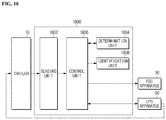
- FIG. 18 is a block diagram illustrating another example of a vehicle control apparatus according to an embodiment of the present disclosure.
- a vehicle control apparatus 1800 includes a sensing unit 1802 , a determination unit 1804 , and a control unit 1806 in the same manner as the vehicle control apparatus 100 ( FIG. 6 ).
- the vehicle control apparatus 1800 may further include an identification unit 1808 .
- the identification unit 1808 may identify that the behavior of the current trailer 10 is unstably operated according to the control of the control unit 1806 .
- the identification unit 1808 may identify that the behavior of the current trailer 10 is stably operated according to the control of the control unit 1806 .
- the identification unit 1808 may identify that the behavior of the current trailer 10 has been stably compensated according to the control of the control unit 1806 .
- the identification unit 1808 by including at least one of a warning device (not shown), a speaker (not shown), and a light emitting member (not shown) which are provided so that a driver can identify the information or state of the vehicle, may identify that the behavior of the current trailer 10 is unstably operated, identify that the behavior of the current trailer 10 is stabilized, and identify that the behavior of the current trailer 10 has been stably compensated, through at least one operation of the warning operation of the warning device, the voice operation of the speaker, and the light emitting operation of the light emitting member.
- the identification unit 1808 by including at least one of an HMI (Human Machine Interface) module (not shown) and a HUD (Head-Up Display) module (not shown) installed as a user interface and a machine so that a driver can grasp the information or status of the vehicle, may identify that the behavior of the current trailer 10 is unstably operated, identify that the behavior of the current trailer 10 is stabilized, and identify that the behavior of the current trailer 10 has been stably compensated, through at least one operation of the HMI message display operation of the HMI module and the HUD message display operation of the HUD module.
- HMI Human Machine Interface
- HUD Head-Up Display
- FIG. 19 is a flowchart illustrating another example of a vehicle control method for a vehicle control apparatus according to an embodiment of the present disclosure
- FIG. 20 is a flowchart illustrating another example of a vehicle control method for a vehicle control apparatus according to an embodiment of the present disclosure.
- FIG. 21 is a flowchart illustrating another example of a vehicle control method for a vehicle control apparatus according to an embodiment of the present disclosure.
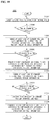
- vehicle control methods 1900 to 2100 of the vehicle control apparatus 1800 ( FIG. 18 ) includes first sensing steps (S 1902 to S 2102 ), first determination steps (S 1904 to S 2104 ), second sensing steps (S 1906 to S 2106 ), second determination steps (S 1908 to S 2108 ), first compensation steps (S 1910 to S 2110 ), third sensing steps (S 1912 to S 2112 ), third determination steps (S 1914 to S 2114 ), and second compensation steps (S 1916 to S 2116 ), respectively, in the same manner as the vehicle control method 1000 ( FIG. 10 ) of the vehicle control apparatus 100 ( FIG. 6 ).
- the vehicle control methods 1900 to 2100 of the vehicle control apparatus 1800 ( FIG. 18 ) may further include a fourth identification step (S 1915 ), a fifth identification step (S 2017 ), and a sixth identification step (S 2119 ).
- the fourth identification step (S 1915 ) may be performed after the third determination step (S 1914 ) and before the second compensation step (S 1916 ).
- the fourth identification step (S 1915 ) may be performed in synchronization with the second compensation step (S 1916 ), though not shown.
- the identification unit 1808 may identify that the behavior of the trailer 10 ( FIG. 18 ) is unstably operated according to the control of the control unit 1806 ( FIG. 18 ).
- the fifth identification step (S 2017 ) may be performed after the second compensation step (S 2016 ).
- the fifth identification step (S 2017 ) may be performed in synchronization with the second compensation step (S 2016 ), though not shown.
- the identification unit 1808 may identify that the behavior of the current trailer ( 10 of FIG. 18 ) is stabilized according to the control of the control unit 1806 ( FIG. 18 ).
- the sixth identification step (S 2119 ) may be performed after the second compensation step (S 2116 ).
- the identification unit 1808 may identify that the behavior of the current trailer 10 ( FIG. 18 ) has been stably compensated according to the control of the control unit 1806 ( FIG. 18 ).
- the determination units 104 , 1404 , and 1804 and the control units 106 , 1406 , and 1806 are described as being separated from each other in order to clearly explain the features of this disclosure, the determination units 104 , 1404 , and 1804 and the control units 106 , 1406 , and 1806 may be an ECU (Electronic Control Unit) (not shown) or an MCU (Micro Control Unit) (not shown) for controlling and determining the overall operation of the vehicle.
- ECU Electronic Control Unit
- MCU Micro Control Unit
- determination units 104 , 1404 , and 1804 and the vehicle control units 106 , 1406 , and 1806 are not limited thereto, and may be any control means and determination means capable of controlling and determining the overall operation of the vehicle.
- the vehicle control apparatuses 100 , 1400 , and 1800 and the vehicle control methods 1000 to 1300 , 1500 to 1700 , and 1900 to 2100 include the sensing units 102 , 1402 , and 1802 , the determination units 104 , 1404 , and 1804 , and the control units 106 , 1406 , and 1806 , and perform the first sensing steps (S 1002 to S 1302 , S 1502 to S 1702 , and S 1902 to S 2102 ), the first determination steps (S 1004 to S 1304 , S 1504 to S 1704 , and S 1904 to S 2104 ), the second sensing steps (S 1006 to S 1306 , S 1506 to S 1706 , and S 1906 to S 2106 ), the second determination steps (S 1008 to S 1308 , S 1508 to S 1708 , and S 1908 to S 2108 ), and the first compensation steps (S 1010 to S 1310 , S 1510 to
- the vehicle control apparatuses 100 , 1400 , and 1800 and the vehicle control methods 1000 to 1300 , 1500 to 1700 , and 1900 to 2100 may transmit a first compensation signal to the ESC apparatus 30 from the respective control units 106 , 1406 , and 1806 to compensate the ESC apparatus 30 in accordance with the set target ESC stable operation control information in order to operate the ESC apparatus 30 in a stable operation state according to at least one of the current trailer load information, current trailer traction information, and current trailer relative angle information when the ESC is in a unstable operation state.
- the vehicle control apparatuses 100 , 1400 , and 1800 and the vehicle control methods 1000 to 1300 , 1500 to 1700 , and 1900 to 2100 may operate the ESC apparatus 30 stably when the trailer 10 is connected.
- the vehicle control apparatuses 100 and 1800 and the vehicle control methods 1200 , 1300 and 1900 to 2100 may include the sensing units 102 and 1802 , the determination units 104 and 1804 , and the control units 106 and 1806 , and may further perform the third sensing steps (S 1212 , S 1312 , and S 1912 to S 2112 ), the first determination steps (S 1214 , S 1314 , and S 1914 to S 2114 ), and the second compensation steps (S 1216 , S 1316 , and S 1916 to S 2116 ).
- the vehicle control apparatuses 100 and 1800 and the vehicle control methods 1200 , 1300 and 1900 to 2100 may further transmit a second compensation signal to the EPS apparatus 50 from the control units 106 and 1806 to compensate the EPS apparatus 50 in accordance with the set target EPS stable operation control information in order to stabilize the behavior of the trailer 10 by a steering operation of the EPS apparatus 50 according to at least one of the current steering angle information and current steering torque information corresponding to the compensated target ESC stable operation control information when the behavior of the trailer 10 is in an unstable operation state.
- the vehicle control apparatuses 100 and 1800 and the vehicle control methods 1200 , 1300 and 1900 to 2100 may stabilize the behavior of the trailer 10 while stably operating the EPS apparatus 50 when the trailer 10 is connected.
- the vehicle control apparatus 1400 and the vehicle control methods 1500 to 1700 may include the identification unit 1408 and further perform the first identification step (S 1509 ), the second identification step (S 1611 ), and the third identification step (S 1713 ).
- the vehicle control apparatus 1400 and the vehicle control methods 1500 to 1700 may identify that the current ESC apparatus 30 is unstably operated, identify that the current ESC apparatus 30 is stably operated, and identify that the current ESC apparatus 30 has been stably compensated.
- the vehicle control apparatus 1400 and the vehicle control methods 1500 to 1700 may suppress anxiety about the operating state of the current ESC apparatus 30 to improve the reliability of the apparatus because a driver can recognize the operation state of the current ESC apparatus 30 .
- vehicle control apparatus 1800 and the vehicle control methods 1900 to 2100 may include the identification unit 1808 and further perform the fourth identification step (S 1915 ), the fifth identification step (S 2017 ), and the sixth identification step (S 2119 ).
- the vehicle control apparatus 1800 and the vehicle control methods 1900 to 2100 may identify that the behavior of the current trailer 10 is unstably operated, identify that the behavior of the current trailer 10 is stabilized, and identify that the behavior of the current trailer 10 has been stably compensated.
- the vehicle control apparatus 1800 and the vehicle control methods 1900 to 2100 may suppress anxiety about the behavior state of the current trailer 10 to improve the reliability of the apparatus because a driver can recognize the behavior state of the current trailer 10 .
- the vehicle control apparatus and the control method thereof can stably operate the ESC apparatus when the trailer is connected.
- the vehicle control apparatus and the control method thereof according to an embodiment of the present disclosure can stabilize the behavior of the trailer while stably operating the EPS apparatus when the trailer is connected.
- the vehicle control apparatus and the control method thereof according to an embodiment of the present disclosure can suppress anxiety about the operating state of the current ESC apparatus to improve the reliability of the apparatus.
- the vehicle control apparatus and the control method thereof according to an embodiment of the present disclosure can suppress anxiety about the behavior state of the current trailer to improve the reliability of the apparatus.
Landscapes
- Engineering & Computer Science (AREA)
- Transportation (AREA)
- Mechanical Engineering (AREA)
- Automation & Control Theory (AREA)
- Chemical & Material Sciences (AREA)
- Combustion & Propulsion (AREA)
- Physics & Mathematics (AREA)
- Mathematical Physics (AREA)
- Steering Control In Accordance With Driving Conditions (AREA)
- Control Of Driving Devices And Active Controlling Of Vehicle (AREA)
Abstract
Description
Claims (18)
Applications Claiming Priority (2)
| Application Number | Priority Date | Filing Date | Title |
|---|---|---|---|
| KR1020170055219A KR102036093B1 (en) | 2017-04-28 | 2017-04-28 | Vehicle control apparatus and control method thereof |
| KR10-2017-0055219 | 2017-04-28 |
Publications (2)
| Publication Number | Publication Date |
|---|---|
| US20180312195A1 US20180312195A1 (en) | 2018-11-01 |
| US10940887B2 true US10940887B2 (en) | 2021-03-09 |
Family
ID=63797105
Family Applications (1)
| Application Number | Title | Priority Date | Filing Date |
|---|---|---|---|
| US15/963,086 Active 2039-06-01 US10940887B2 (en) | 2017-04-28 | 2018-04-25 | Vehicle control apparatus and control method thereof |
Country Status (4)
| Country | Link |
|---|---|
| US (1) | US10940887B2 (en) |
| KR (1) | KR102036093B1 (en) |
| CN (1) | CN108791275B (en) |
| DE (1) | DE102018206528A1 (en) |
Families Citing this family (5)
| Publication number | Priority date | Publication date | Assignee | Title |
|---|---|---|---|---|
| CN109532723B (en) * | 2018-12-24 | 2021-11-02 | 重庆工商大学 | A method for identifying the trailer state and the drum test state of an automobile |
| EP4149822B1 (en) * | 2020-05-11 | 2025-09-10 | Volvo Truck Corporation | A dolly vehicle with adjustable drawbar mechanism |
| US11560026B2 (en) * | 2020-11-06 | 2023-01-24 | GM Global Technology Operations LLC | System and method for hitch angle estimation |
| US11845497B2 (en) * | 2020-11-09 | 2023-12-19 | Fca Us Llc | Method and system for flat tow stabilization of a vehicle using electrical power steering |
| KR20230158681A (en) | 2022-05-11 | 2023-11-21 | 현대자동차주식회사 | Vehicle and control method thereof |
Citations (70)
| Publication number | Priority date | Publication date | Assignee | Title |
|---|---|---|---|---|
| JP2001206211A (en) | 2000-01-27 | 2001-07-31 | Nissan Diesel Motor Co Ltd | Control device for vehicle behavior |
| US6523911B1 (en) * | 1999-06-30 | 2003-02-25 | Robert Bosch Gmbh | Method and device for stabilizing a vehicle |
| US20040021291A1 (en) * | 2001-02-21 | 2004-02-05 | Jurgen Haug | Movable trailer hitch for avoiding pendulous movements in vehicle-trailer arrangements |
| KR20040042599A (en) | 2002-11-15 | 2004-05-20 | 현대자동차주식회사 | auto hitch ball device of a trailer |
| US20040232652A1 (en) * | 2003-05-23 | 2004-11-25 | Namuduri Chandra Sekhar | Trailer stability control apparatus |
| US20050206229A1 (en) * | 2004-03-18 | 2005-09-22 | Ford Global Technologies, Llc | Method of controlling an automotive vehicle having a trailer using rear axle slip angle |
| US20050206231A1 (en) * | 2004-03-18 | 2005-09-22 | Ford Global Technologies, Llc | Method and apparatus for controlling an automotive vehicle using brake-steer and normal load adjustment |
| US20050206224A1 (en) * | 2004-03-18 | 2005-09-22 | Ford Global Technologies, Llc | Method of controlling an automotive vehicle having a trailer |
| US20050206235A1 (en) * | 2004-03-18 | 2005-09-22 | Ford Global Technologies, Llc | Method and apparatus for controlling a trailer and an automotive vehicle with a yaw stability control system |
| US20050206234A1 (en) * | 2004-03-18 | 2005-09-22 | Ford Global Technologies, Llc | Method and apparatus to enhance brake-steer of a vehicle using a controllable suspension component |
| US20050236894A1 (en) * | 2004-03-18 | 2005-10-27 | Ford Global Technologies, Llc | Control system for brake-steer assisted parking and method therefor |
| JP2006507183A (en) | 2002-11-22 | 2006-03-02 | ダイムラークライスラー・アクチェンゲゼルシャフト | Method and apparatus for stabilizing articulated vehicles |
| US20060206253A1 (en) * | 2005-03-14 | 2006-09-14 | Robert Bosch Gmbh | Method and system of controlling a vehicle in the presence of a disturbance |
| US20060204347A1 (en) * | 2002-11-08 | 2006-09-14 | Continental Teves Ag & Co. Ohg | Method and device for stabilizing a vehicle combination |
| US20060229782A1 (en) * | 2005-04-06 | 2006-10-12 | Weiwen Deng | Vehicle-trailer stability and handling performance improvement using rear-wheel steering control |
| US20060235589A1 (en) * | 2005-04-14 | 2006-10-19 | Weiwen Deng | Adaptive rear-wheel steer open-loop control for vehicle-trailer system |
| US7272481B2 (en) * | 2003-06-30 | 2007-09-18 | Kelsey-Hayes Company | Method and apparatus for detecting and correcting trailer induced yaw movements in a towing vehicle |
| US20070260385A1 (en) * | 2006-05-03 | 2007-11-08 | Tandy Engineering & Associates, Inc. | Stability enhancing system for tow-vehicle and trailer assembly combination with two processors |
| US20070260386A1 (en) * | 2006-05-03 | 2007-11-08 | Tandy Engineering & Associates, Inc. | Stability enhancing system for tow-vehicle towing trailer-assembly with trailer sensors |
| US20080036296A1 (en) * | 2006-08-11 | 2008-02-14 | Robert Bosch Gmbh | Closed-loop control for trailer sway mitigation |
| US20080172163A1 (en) * | 2007-01-11 | 2008-07-17 | Ford Motor Company | Trailer Sway Control With Trailer Brake Intervention |
| US20080177454A1 (en) * | 2007-01-18 | 2008-07-24 | Bond James R | Integrated trailer brake control system |
| US20080309156A1 (en) * | 2007-06-15 | 2008-12-18 | Kds Controls | Brake control system and method |
| US20090005946A1 (en) * | 2007-06-29 | 2009-01-01 | Honda Motor Co., Ltd. | Movement stabilizing apparatus for combination vehicle |
| US20090093928A1 (en) * | 2007-10-05 | 2009-04-09 | Anya Lynn Getman | Trailer Oscillation Detection and Compensation Method For A Vehicle And Trailer Combination |
| US20090105906A1 (en) * | 2007-10-19 | 2009-04-23 | James Hackney | Method and Apparatus for Vehicle Sway Detection and Reduction |
| US20090198425A1 (en) * | 2008-02-06 | 2009-08-06 | Ford Global Technologies, Llc | Trailer sway control with reverse sensors |
| US20090210112A1 (en) * | 2004-06-25 | 2009-08-20 | Continental Teves Ag & Co. Ohg | Process and device for stabilising a vehicle |
| US20090219148A1 (en) * | 2007-10-29 | 2009-09-03 | Donald Thomas, Llc | Wireless vehicle trailer monitoring and control system |
| US20090228182A1 (en) * | 2005-11-22 | 2009-09-10 | Continential Teves Ag & Co. Ohg | Method and Driving Dynamics Control System for Stabilizing a Car-Trailer Combination |
| US20090306861A1 (en) * | 2006-06-27 | 2009-12-10 | Andreas Schumann | Method and Control Device for Identifying a Trailer Operation of a Towing Vehicle |
| US20100152989A1 (en) * | 2008-11-25 | 2010-06-17 | Bruce Edward Smith | Universal trailer mounted proportional brake controller |
| JP2010167815A (en) | 2009-01-20 | 2010-08-05 | Hino Motors Ltd | Combination vehicle, combination pressure control method in the combination vehicle and program |
| US20100332049A1 (en) * | 2009-06-24 | 2010-12-30 | Robert Bosch Gmbh | Method and system of determining load characteristics of a trailer |
| US20110029210A1 (en) * | 2009-07-30 | 2011-02-03 | Wu Hsien-Cheng | Holistic control for stabilizing vehicle-trailer swaying |
| US20110032484A1 (en) * | 2009-08-07 | 2011-02-10 | Trevor Seal | Apparatus, system, and method for vehicle mounted display device |
| US20110202238A1 (en) * | 2007-08-03 | 2011-08-18 | Cambridge Enterprise Limited | Active steering controller |
| US8060288B2 (en) * | 2009-03-20 | 2011-11-15 | Toyota Motor Engineering & Manufacturing North America, Inc. | Control system and method to inhibit automatic transmission downshifting during trailer sway |
| US20120024081A1 (en) * | 2010-07-29 | 2012-02-02 | Douglas Baker | Trailer hitch monitoring apparatus and method |
| US8311693B2 (en) * | 2010-11-19 | 2012-11-13 | Robert Bosch Gmbh | Energy management for hybrid electric vehicle during trailer sway |
| US20130038436A1 (en) * | 2011-08-09 | 2013-02-14 | Continental Automotive Systems, Inc. | Smart trailer |
| US20130253814A1 (en) * | 2012-03-24 | 2013-09-26 | Alvin R. Wirthlin | System and Method for Gauging Safe Towing Parameters |
| US20140110918A1 (en) * | 2012-10-24 | 2014-04-24 | Cequent Performance Products, Inc. | Overload indicator |
| US20140267688A1 (en) * | 2011-04-19 | 2014-09-18 | Ford Global Technologies, Llc | Display system utilizing vehicle and trailer dynamics |
| US20140327229A1 (en) * | 2013-05-02 | 2014-11-06 | Roger W. Scharf | Tongue Weight Donut Scale |
| US9026311B1 (en) * | 2013-03-13 | 2015-05-05 | Tuson Rv Brakes, Llc | Trailer sway detection and method for reducing trailer sway utilizing trailer brakes |
| US20150165850A1 (en) * | 2013-12-13 | 2015-06-18 | Honda Motor Co., Ltd. | Method and system for stability control |
| KR20150117828A (en) | 2014-04-11 | 2015-10-21 | 주식회사 만도 | Apparatus for controlling vehicle and method for controlling thereof |
| US20150306929A1 (en) * | 2013-05-22 | 2015-10-29 | Kevin McAllister | Ball mount for measuring tongue weight of a trailer |
| KR101595348B1 (en) | 2014-10-28 | 2016-02-18 | 주식회사 만도 | Mounting assistance apparatus and mounting assistance method thereof |
| US9340228B2 (en) * | 2014-10-13 | 2016-05-17 | Ford Global Technologies, Llc | Trailer motion and parameter estimation system |
| US20160231165A1 (en) * | 2015-02-05 | 2016-08-11 | R. Douglas Fredrickson | Weight Sensing Vehicle Hitch |
| US20160236526A1 (en) * | 2015-02-17 | 2016-08-18 | Daniel Robert Shepard | Dual Purpose Hitch Sensor |
| US9513103B2 (en) * | 2011-04-19 | 2016-12-06 | Ford Global Technologies, Llc | Hitch angle sensor assembly |
| KR20160139457A (en) | 2015-05-27 | 2016-12-07 | 주식회사 만도 | Vehicle type Trailer Stability Control method ans system |
| US9566911B2 (en) * | 2007-03-21 | 2017-02-14 | Ford Global Technologies, Llc | Vehicle trailer angle detection system and method |
| US20170106865A1 (en) * | 2015-10-19 | 2017-04-20 | Ford Global Technologies, Llc | Speed control for motor vehicles |
| US20170129403A1 (en) * | 2015-11-11 | 2017-05-11 | Ford Global Technologies, Llc | Trailer monitoring system and method |
| US20170177949A1 (en) * | 2015-12-17 | 2017-06-22 | Ford Global Technologies, Llc | Trailer type identification system |
| US20170305436A1 (en) * | 2014-10-06 | 2017-10-26 | Jaguar Land Rover Limited | System and method for determining whether a trailer is attached to a vehicle |
| US9908377B2 (en) * | 2015-12-01 | 2018-03-06 | Hayes Towing Electronics LLC | Apparatus and method for sway control |
| US9956965B1 (en) * | 2016-11-01 | 2018-05-01 | Michael Hall | Tongue weight determination |
| US9963004B2 (en) * | 2014-07-28 | 2018-05-08 | Ford Global Technologies, Llc | Trailer sway warning system and method |
| US10005492B2 (en) * | 2016-02-18 | 2018-06-26 | Ford Global Technologies, Llc | Trailer length and hitch angle bias estimation |
| US10065676B2 (en) * | 2013-04-26 | 2018-09-04 | Jaguar Land Rover Limited | System for a towing vehicle |
| US10155478B2 (en) * | 2015-12-17 | 2018-12-18 | Ford Global Technologies, Llc | Centerline method for trailer hitch angle detection |
| US10196088B2 (en) * | 2011-04-19 | 2019-02-05 | Ford Global Technologies, Llc | Target monitoring system and method |
| US20190092388A1 (en) * | 2017-09-27 | 2019-03-28 | Ford Global Technologies, Llc | Adaptive steering control for robustness to errors in estimated or user-supplied trailer parameters |
| US20190118858A1 (en) * | 2017-10-24 | 2019-04-25 | Schaeffler Technologies AG & Co. KG | Adaptive wheel base rear steering control |
| US20200156624A1 (en) * | 2018-11-16 | 2020-05-21 | Volkswagen Aktiengesellschaft | Brake system for a transportation vehicle, transportation vehicle with a brake system, and method for operating a brake system |
Family Cites Families (5)
| Publication number | Priority date | Publication date | Assignee | Title |
|---|---|---|---|---|
| CN103661367A (en) * | 2012-09-25 | 2014-03-26 | 上海韵风文化传播有限公司 | Self-adaptive active steering control method capable of improving handling stability of tractor-trailer |
| KR101988510B1 (en) * | 2014-04-11 | 2019-09-30 | 주식회사 만도 | Apparatus and method for electronic stability control of vehicle |
| DE102014010590A1 (en) * | 2014-07-16 | 2015-01-15 | Daimler Ag | Method for stabilizing a vehicle |
| DE102015215802B4 (en) * | 2015-08-19 | 2024-06-06 | Zf Friedrichshafen Ag | Stabilization of a vehicle combination |
| KR101784708B1 (en) | 2015-11-11 | 2017-10-12 | 주식회사 대한전광 | Mesh fence type illumination system |
-
2017
- 2017-04-28 KR KR1020170055219A patent/KR102036093B1/en active Active
-
2018
- 2018-04-25 US US15/963,086 patent/US10940887B2/en active Active
- 2018-04-26 DE DE102018206528.4A patent/DE102018206528A1/en active Pending
- 2018-04-28 CN CN201810403020.1A patent/CN108791275B/en active Active
Patent Citations (71)
| Publication number | Priority date | Publication date | Assignee | Title |
|---|---|---|---|---|
| US6523911B1 (en) * | 1999-06-30 | 2003-02-25 | Robert Bosch Gmbh | Method and device for stabilizing a vehicle |
| JP2001206211A (en) | 2000-01-27 | 2001-07-31 | Nissan Diesel Motor Co Ltd | Control device for vehicle behavior |
| US20040021291A1 (en) * | 2001-02-21 | 2004-02-05 | Jurgen Haug | Movable trailer hitch for avoiding pendulous movements in vehicle-trailer arrangements |
| US20060204347A1 (en) * | 2002-11-08 | 2006-09-14 | Continental Teves Ag & Co. Ohg | Method and device for stabilizing a vehicle combination |
| KR20040042599A (en) | 2002-11-15 | 2004-05-20 | 현대자동차주식회사 | auto hitch ball device of a trailer |
| JP2006507183A (en) | 2002-11-22 | 2006-03-02 | ダイムラークライスラー・アクチェンゲゼルシャフト | Method and apparatus for stabilizing articulated vehicles |
| US20060125313A1 (en) * | 2002-11-22 | 2006-06-15 | Daimlerchrysler Ag | Method and device for stabilizing a semi-trailer |
| US20040232652A1 (en) * | 2003-05-23 | 2004-11-25 | Namuduri Chandra Sekhar | Trailer stability control apparatus |
| US7272481B2 (en) * | 2003-06-30 | 2007-09-18 | Kelsey-Hayes Company | Method and apparatus for detecting and correcting trailer induced yaw movements in a towing vehicle |
| US20050236894A1 (en) * | 2004-03-18 | 2005-10-27 | Ford Global Technologies, Llc | Control system for brake-steer assisted parking and method therefor |
| US20050206234A1 (en) * | 2004-03-18 | 2005-09-22 | Ford Global Technologies, Llc | Method and apparatus to enhance brake-steer of a vehicle using a controllable suspension component |
| US20050206235A1 (en) * | 2004-03-18 | 2005-09-22 | Ford Global Technologies, Llc | Method and apparatus for controlling a trailer and an automotive vehicle with a yaw stability control system |
| US20050206224A1 (en) * | 2004-03-18 | 2005-09-22 | Ford Global Technologies, Llc | Method of controlling an automotive vehicle having a trailer |
| US20050206231A1 (en) * | 2004-03-18 | 2005-09-22 | Ford Global Technologies, Llc | Method and apparatus for controlling an automotive vehicle using brake-steer and normal load adjustment |
| US20050206229A1 (en) * | 2004-03-18 | 2005-09-22 | Ford Global Technologies, Llc | Method of controlling an automotive vehicle having a trailer using rear axle slip angle |
| US20090210112A1 (en) * | 2004-06-25 | 2009-08-20 | Continental Teves Ag & Co. Ohg | Process and device for stabilising a vehicle |
| US20060206253A1 (en) * | 2005-03-14 | 2006-09-14 | Robert Bosch Gmbh | Method and system of controlling a vehicle in the presence of a disturbance |
| US20060229782A1 (en) * | 2005-04-06 | 2006-10-12 | Weiwen Deng | Vehicle-trailer stability and handling performance improvement using rear-wheel steering control |
| US20060235589A1 (en) * | 2005-04-14 | 2006-10-19 | Weiwen Deng | Adaptive rear-wheel steer open-loop control for vehicle-trailer system |
| US20090228182A1 (en) * | 2005-11-22 | 2009-09-10 | Continential Teves Ag & Co. Ohg | Method and Driving Dynamics Control System for Stabilizing a Car-Trailer Combination |
| US20070260385A1 (en) * | 2006-05-03 | 2007-11-08 | Tandy Engineering & Associates, Inc. | Stability enhancing system for tow-vehicle and trailer assembly combination with two processors |
| US20070260386A1 (en) * | 2006-05-03 | 2007-11-08 | Tandy Engineering & Associates, Inc. | Stability enhancing system for tow-vehicle towing trailer-assembly with trailer sensors |
| US20090306861A1 (en) * | 2006-06-27 | 2009-12-10 | Andreas Schumann | Method and Control Device for Identifying a Trailer Operation of a Towing Vehicle |
| US20080036296A1 (en) * | 2006-08-11 | 2008-02-14 | Robert Bosch Gmbh | Closed-loop control for trailer sway mitigation |
| US20080172163A1 (en) * | 2007-01-11 | 2008-07-17 | Ford Motor Company | Trailer Sway Control With Trailer Brake Intervention |
| US20080177454A1 (en) * | 2007-01-18 | 2008-07-24 | Bond James R | Integrated trailer brake control system |
| US9566911B2 (en) * | 2007-03-21 | 2017-02-14 | Ford Global Technologies, Llc | Vehicle trailer angle detection system and method |
| US20080309156A1 (en) * | 2007-06-15 | 2008-12-18 | Kds Controls | Brake control system and method |
| US20090005946A1 (en) * | 2007-06-29 | 2009-01-01 | Honda Motor Co., Ltd. | Movement stabilizing apparatus for combination vehicle |
| US20110202238A1 (en) * | 2007-08-03 | 2011-08-18 | Cambridge Enterprise Limited | Active steering controller |
| US20090093928A1 (en) * | 2007-10-05 | 2009-04-09 | Anya Lynn Getman | Trailer Oscillation Detection and Compensation Method For A Vehicle And Trailer Combination |
| US20090105906A1 (en) * | 2007-10-19 | 2009-04-23 | James Hackney | Method and Apparatus for Vehicle Sway Detection and Reduction |
| US20090219148A1 (en) * | 2007-10-29 | 2009-09-03 | Donald Thomas, Llc | Wireless vehicle trailer monitoring and control system |
| US20090198425A1 (en) * | 2008-02-06 | 2009-08-06 | Ford Global Technologies, Llc | Trailer sway control with reverse sensors |
| US20100152989A1 (en) * | 2008-11-25 | 2010-06-17 | Bruce Edward Smith | Universal trailer mounted proportional brake controller |
| JP2010167815A (en) | 2009-01-20 | 2010-08-05 | Hino Motors Ltd | Combination vehicle, combination pressure control method in the combination vehicle and program |
| US8060288B2 (en) * | 2009-03-20 | 2011-11-15 | Toyota Motor Engineering & Manufacturing North America, Inc. | Control system and method to inhibit automatic transmission downshifting during trailer sway |
| US20100332049A1 (en) * | 2009-06-24 | 2010-12-30 | Robert Bosch Gmbh | Method and system of determining load characteristics of a trailer |
| US20110029210A1 (en) * | 2009-07-30 | 2011-02-03 | Wu Hsien-Cheng | Holistic control for stabilizing vehicle-trailer swaying |
| US20110032484A1 (en) * | 2009-08-07 | 2011-02-10 | Trevor Seal | Apparatus, system, and method for vehicle mounted display device |
| US20120024081A1 (en) * | 2010-07-29 | 2012-02-02 | Douglas Baker | Trailer hitch monitoring apparatus and method |
| US8311693B2 (en) * | 2010-11-19 | 2012-11-13 | Robert Bosch Gmbh | Energy management for hybrid electric vehicle during trailer sway |
| US9513103B2 (en) * | 2011-04-19 | 2016-12-06 | Ford Global Technologies, Llc | Hitch angle sensor assembly |
| US20140267688A1 (en) * | 2011-04-19 | 2014-09-18 | Ford Global Technologies, Llc | Display system utilizing vehicle and trailer dynamics |
| US10196088B2 (en) * | 2011-04-19 | 2019-02-05 | Ford Global Technologies, Llc | Target monitoring system and method |
| US20130038436A1 (en) * | 2011-08-09 | 2013-02-14 | Continental Automotive Systems, Inc. | Smart trailer |
| US20130253814A1 (en) * | 2012-03-24 | 2013-09-26 | Alvin R. Wirthlin | System and Method for Gauging Safe Towing Parameters |
| US20140110918A1 (en) * | 2012-10-24 | 2014-04-24 | Cequent Performance Products, Inc. | Overload indicator |
| US9026311B1 (en) * | 2013-03-13 | 2015-05-05 | Tuson Rv Brakes, Llc | Trailer sway detection and method for reducing trailer sway utilizing trailer brakes |
| US10065676B2 (en) * | 2013-04-26 | 2018-09-04 | Jaguar Land Rover Limited | System for a towing vehicle |
| US20140327229A1 (en) * | 2013-05-02 | 2014-11-06 | Roger W. Scharf | Tongue Weight Donut Scale |
| US20150306929A1 (en) * | 2013-05-22 | 2015-10-29 | Kevin McAllister | Ball mount for measuring tongue weight of a trailer |
| US20150165850A1 (en) * | 2013-12-13 | 2015-06-18 | Honda Motor Co., Ltd. | Method and system for stability control |
| KR20150117828A (en) | 2014-04-11 | 2015-10-21 | 주식회사 만도 | Apparatus for controlling vehicle and method for controlling thereof |
| US9963004B2 (en) * | 2014-07-28 | 2018-05-08 | Ford Global Technologies, Llc | Trailer sway warning system and method |
| US20170305436A1 (en) * | 2014-10-06 | 2017-10-26 | Jaguar Land Rover Limited | System and method for determining whether a trailer is attached to a vehicle |
| US9340228B2 (en) * | 2014-10-13 | 2016-05-17 | Ford Global Technologies, Llc | Trailer motion and parameter estimation system |
| KR101595348B1 (en) | 2014-10-28 | 2016-02-18 | 주식회사 만도 | Mounting assistance apparatus and mounting assistance method thereof |
| US20160231165A1 (en) * | 2015-02-05 | 2016-08-11 | R. Douglas Fredrickson | Weight Sensing Vehicle Hitch |
| US20160236526A1 (en) * | 2015-02-17 | 2016-08-18 | Daniel Robert Shepard | Dual Purpose Hitch Sensor |
| KR20160139457A (en) | 2015-05-27 | 2016-12-07 | 주식회사 만도 | Vehicle type Trailer Stability Control method ans system |
| US20170106865A1 (en) * | 2015-10-19 | 2017-04-20 | Ford Global Technologies, Llc | Speed control for motor vehicles |
| US20170129403A1 (en) * | 2015-11-11 | 2017-05-11 | Ford Global Technologies, Llc | Trailer monitoring system and method |
| US9908377B2 (en) * | 2015-12-01 | 2018-03-06 | Hayes Towing Electronics LLC | Apparatus and method for sway control |
| US20170177949A1 (en) * | 2015-12-17 | 2017-06-22 | Ford Global Technologies, Llc | Trailer type identification system |
| US10155478B2 (en) * | 2015-12-17 | 2018-12-18 | Ford Global Technologies, Llc | Centerline method for trailer hitch angle detection |
| US10005492B2 (en) * | 2016-02-18 | 2018-06-26 | Ford Global Technologies, Llc | Trailer length and hitch angle bias estimation |
| US9956965B1 (en) * | 2016-11-01 | 2018-05-01 | Michael Hall | Tongue weight determination |
| US20190092388A1 (en) * | 2017-09-27 | 2019-03-28 | Ford Global Technologies, Llc | Adaptive steering control for robustness to errors in estimated or user-supplied trailer parameters |
| US20190118858A1 (en) * | 2017-10-24 | 2019-04-25 | Schaeffler Technologies AG & Co. KG | Adaptive wheel base rear steering control |
| US20200156624A1 (en) * | 2018-11-16 | 2020-05-21 | Volkswagen Aktiengesellschaft | Brake system for a transportation vehicle, transportation vehicle with a brake system, and method for operating a brake system |
Non-Patent Citations (2)
| Title |
|---|
| Office Action dated Mar. 20, 2019 for Korean Patent Application No. 10-2017-0055219 and its English machine translation by Global Dossier. |
| Office Action dated Oct. 4, 2018 for Korean Patent Application No. 10-2017-0055219 and its English machine translation by Global Dossier. |
Also Published As
| Publication number | Publication date |
|---|---|
| KR20180121049A (en) | 2018-11-07 |
| KR102036093B1 (en) | 2019-10-25 |
| US20180312195A1 (en) | 2018-11-01 |
| CN108791275A (en) | 2018-11-13 |
| CN108791275B (en) | 2021-08-27 |
| DE102018206528A1 (en) | 2018-10-31 |
Similar Documents
| Publication | Publication Date | Title |
|---|---|---|
| US10940887B2 (en) | Vehicle control apparatus and control method thereof | |
| US9834213B2 (en) | Lane keeping assist apparatus | |
| US9862415B2 (en) | Lane keeping assist apparatus | |
| US9868422B2 (en) | Control apparatus of brake system and method of controlling the same | |
| US11192531B2 (en) | Vehicle control apparatus and method for controlling the same | |
| US20190315321A1 (en) | Vehicle control apparatus and vehicle control method | |
| US10124828B2 (en) | Autonomous vehicle steering control methods and systems | |
| KR20210146488A (en) | Method and apparatus for controlling autonomous driving | |
| CN114987600B (en) | Control method and device for maintaining central position of steering wheel of automobile and automobile | |
| KR20120053763A (en) | Apparatus for recognizing position sensor in tire pressure monitoring system and method thereof | |
| US20160305389A1 (en) | Vehicle control device | |
| CN112118990A (en) | Apparatus for vehicle trailers and systems and related methods thereof | |
| US10696296B2 (en) | Vehicle control apparatus and method for controlling vehicle | |
| US20140236427A1 (en) | Electric power steering control apparatus and method | |
| US20240424855A1 (en) | Vehicle | |
| US20170313317A1 (en) | Vehicle control system | |
| KR102339680B1 (en) | System for controlling multipurpose four-wheel electric vehicle | |
| KR101592590B1 (en) | Method for controlling compulsion drive of Motor Driven Power Steering for testing Smart Parking Assist System | |
| KR102693290B1 (en) | Electronic power steering system and controlling method thereof | |
| KR101672036B1 (en) | Method for judging error sensor of electronic stability controlled system of vehicle | |
| CN119527276B (en) | Control method for zero calibration of lane centering steering wheel | |
| US12545323B2 (en) | Drive assist device | |
| US12472952B2 (en) | Vehicle including a vehicle platform that transitions to a wake mode according to a wake command | |
| US12379732B2 (en) | Remote driving method, remote driving device and computer-readable medium | |
| US12134381B2 (en) | Driver support device |
Legal Events
| Date | Code | Title | Description |
|---|---|---|---|
| FEPP | Fee payment procedure |
Free format text: ENTITY STATUS SET TO UNDISCOUNTED (ORIGINAL EVENT CODE: BIG.); ENTITY STATUS OF PATENT OWNER: LARGE ENTITY |
|
| AS | Assignment |
Owner name: MANDO CORPORATION, KOREA, REPUBLIC OF Free format text: ASSIGNMENT OF ASSIGNORS INTEREST;ASSIGNOR:TAE, HYUN CHUL;REEL/FRAME:046026/0355 Effective date: 20180419 |
|
| STPP | Information on status: patent application and granting procedure in general |
Free format text: DOCKETED NEW CASE - READY FOR EXAMINATION |
|
| STPP | Information on status: patent application and granting procedure in general |
Free format text: RESPONSE TO NON-FINAL OFFICE ACTION ENTERED AND FORWARDED TO EXAMINER |
|
| STCF | Information on status: patent grant |
Free format text: PATENTED CASE |
|
| AS | Assignment |
Owner name: HL MANDO CORPORATION, KOREA, REPUBLIC OF Free format text: CHANGE OF NAME;ASSIGNOR:MANDO CORPORATION;REEL/FRAME:062152/0127 Effective date: 20220905 |
|
| MAFP | Maintenance fee payment |
Free format text: PAYMENT OF MAINTENANCE FEE, 4TH YEAR, LARGE ENTITY (ORIGINAL EVENT CODE: M1551); ENTITY STATUS OF PATENT OWNER: LARGE ENTITY Year of fee payment: 4 |