US10928128B2 - Preparing hydrocarbon streams for storage - Google Patents
Preparing hydrocarbon streams for storage Download PDFInfo
- Publication number
- US10928128B2 US10928128B2 US14/974,602 US201514974602A US10928128B2 US 10928128 B2 US10928128 B2 US 10928128B2 US 201514974602 A US201514974602 A US 201514974602A US 10928128 B2 US10928128 B2 US 10928128B2
- Authority
- US
- United States
- Prior art keywords
- liquid
- product
- vapor
- vessels
- vessel
- Prior art date
- Legal status (The legal status is an assumption and is not a legal conclusion. Google has not performed a legal analysis and makes no representation as to the accuracy of the status listed.)
- Active, expires
Links
Images


Classifications
-
- F—MECHANICAL ENGINEERING; LIGHTING; HEATING; WEAPONS; BLASTING
- F25—REFRIGERATION OR COOLING; COMBINED HEATING AND REFRIGERATION SYSTEMS; HEAT PUMP SYSTEMS; MANUFACTURE OR STORAGE OF ICE; LIQUEFACTION SOLIDIFICATION OF GASES
- F25J—LIQUEFACTION, SOLIDIFICATION OR SEPARATION OF GASES OR GASEOUS OR LIQUEFIED GASEOUS MIXTURES BY PRESSURE AND COLD TREATMENT OR BY BRINGING THEM INTO THE SUPERCRITICAL STATE
- F25J3/00—Processes or apparatus for separating the constituents of gaseous or liquefied gaseous mixtures involving the use of liquefaction or solidification
- F25J3/08—Separating gaseous impurities from gases or gaseous mixtures or from liquefied gases or liquefied gaseous mixtures
-
- F—MECHANICAL ENGINEERING; LIGHTING; HEATING; WEAPONS; BLASTING
- F25—REFRIGERATION OR COOLING; COMBINED HEATING AND REFRIGERATION SYSTEMS; HEAT PUMP SYSTEMS; MANUFACTURE OR STORAGE OF ICE; LIQUEFACTION SOLIDIFICATION OF GASES
- F25J—LIQUEFACTION, SOLIDIFICATION OR SEPARATION OF GASES OR GASEOUS OR LIQUEFIED GASEOUS MIXTURES BY PRESSURE AND COLD TREATMENT OR BY BRINGING THEM INTO THE SUPERCRITICAL STATE
- F25J3/00—Processes or apparatus for separating the constituents of gaseous or liquefied gaseous mixtures involving the use of liquefaction or solidification
- F25J3/02—Processes or apparatus for separating the constituents of gaseous or liquefied gaseous mixtures involving the use of liquefaction or solidification by rectification, i.e. by continuous interchange of heat and material between a vapour stream and a liquid stream
- F25J3/0204—Processes or apparatus for separating the constituents of gaseous or liquefied gaseous mixtures involving the use of liquefaction or solidification by rectification, i.e. by continuous interchange of heat and material between a vapour stream and a liquid stream characterised by the feed stream
- F25J3/0209—Natural gas or substitute natural gas
- F25J3/0214—Liquefied natural gas
-
- F—MECHANICAL ENGINEERING; LIGHTING; HEATING; WEAPONS; BLASTING
- F25—REFRIGERATION OR COOLING; COMBINED HEATING AND REFRIGERATION SYSTEMS; HEAT PUMP SYSTEMS; MANUFACTURE OR STORAGE OF ICE; LIQUEFACTION SOLIDIFICATION OF GASES
- F25J—LIQUEFACTION, SOLIDIFICATION OR SEPARATION OF GASES OR GASEOUS OR LIQUEFIED GASEOUS MIXTURES BY PRESSURE AND COLD TREATMENT OR BY BRINGING THEM INTO THE SUPERCRITICAL STATE
- F25J3/00—Processes or apparatus for separating the constituents of gaseous or liquefied gaseous mixtures involving the use of liquefaction or solidification
- F25J3/02—Processes or apparatus for separating the constituents of gaseous or liquefied gaseous mixtures involving the use of liquefaction or solidification by rectification, i.e. by continuous interchange of heat and material between a vapour stream and a liquid stream
- F25J3/0204—Processes or apparatus for separating the constituents of gaseous or liquefied gaseous mixtures involving the use of liquefaction or solidification by rectification, i.e. by continuous interchange of heat and material between a vapour stream and a liquid stream characterised by the feed stream
- F25J3/0219—Refinery gas, cracking gas, coke oven gas, gaseous mixtures containing aliphatic unsaturated CnHm or gaseous mixtures of undefined nature
-
- F—MECHANICAL ENGINEERING; LIGHTING; HEATING; WEAPONS; BLASTING
- F25—REFRIGERATION OR COOLING; COMBINED HEATING AND REFRIGERATION SYSTEMS; HEAT PUMP SYSTEMS; MANUFACTURE OR STORAGE OF ICE; LIQUEFACTION SOLIDIFICATION OF GASES
- F25J—LIQUEFACTION, SOLIDIFICATION OR SEPARATION OF GASES OR GASEOUS OR LIQUEFIED GASEOUS MIXTURES BY PRESSURE AND COLD TREATMENT OR BY BRINGING THEM INTO THE SUPERCRITICAL STATE
- F25J3/00—Processes or apparatus for separating the constituents of gaseous or liquefied gaseous mixtures involving the use of liquefaction or solidification
- F25J3/02—Processes or apparatus for separating the constituents of gaseous or liquefied gaseous mixtures involving the use of liquefaction or solidification by rectification, i.e. by continuous interchange of heat and material between a vapour stream and a liquid stream
- F25J3/0228—Processes or apparatus for separating the constituents of gaseous or liquefied gaseous mixtures involving the use of liquefaction or solidification by rectification, i.e. by continuous interchange of heat and material between a vapour stream and a liquid stream characterised by the separated product stream
- F25J3/0233—Processes or apparatus for separating the constituents of gaseous or liquefied gaseous mixtures involving the use of liquefaction or solidification by rectification, i.e. by continuous interchange of heat and material between a vapour stream and a liquid stream characterised by the separated product stream separation of CnHm with 1 carbon atom or more
-
- F—MECHANICAL ENGINEERING; LIGHTING; HEATING; WEAPONS; BLASTING
- F25—REFRIGERATION OR COOLING; COMBINED HEATING AND REFRIGERATION SYSTEMS; HEAT PUMP SYSTEMS; MANUFACTURE OR STORAGE OF ICE; LIQUEFACTION SOLIDIFICATION OF GASES
- F25J—LIQUEFACTION, SOLIDIFICATION OR SEPARATION OF GASES OR GASEOUS OR LIQUEFIED GASEOUS MIXTURES BY PRESSURE AND COLD TREATMENT OR BY BRINGING THEM INTO THE SUPERCRITICAL STATE
- F25J3/00—Processes or apparatus for separating the constituents of gaseous or liquefied gaseous mixtures involving the use of liquefaction or solidification
- F25J3/02—Processes or apparatus for separating the constituents of gaseous or liquefied gaseous mixtures involving the use of liquefaction or solidification by rectification, i.e. by continuous interchange of heat and material between a vapour stream and a liquid stream
- F25J3/0228—Processes or apparatus for separating the constituents of gaseous or liquefied gaseous mixtures involving the use of liquefaction or solidification by rectification, i.e. by continuous interchange of heat and material between a vapour stream and a liquid stream characterised by the separated product stream
- F25J3/0238—Processes or apparatus for separating the constituents of gaseous or liquefied gaseous mixtures involving the use of liquefaction or solidification by rectification, i.e. by continuous interchange of heat and material between a vapour stream and a liquid stream characterised by the separated product stream separation of CnHm with 2 carbon atoms or more
-
- F—MECHANICAL ENGINEERING; LIGHTING; HEATING; WEAPONS; BLASTING
- F25—REFRIGERATION OR COOLING; COMBINED HEATING AND REFRIGERATION SYSTEMS; HEAT PUMP SYSTEMS; MANUFACTURE OR STORAGE OF ICE; LIQUEFACTION SOLIDIFICATION OF GASES
- F25J—LIQUEFACTION, SOLIDIFICATION OR SEPARATION OF GASES OR GASEOUS OR LIQUEFIED GASEOUS MIXTURES BY PRESSURE AND COLD TREATMENT OR BY BRINGING THEM INTO THE SUPERCRITICAL STATE
- F25J2200/00—Processes or apparatus using separation by rectification
- F25J2200/74—Refluxing the column with at least a part of the partially condensed overhead gas
-
- F—MECHANICAL ENGINEERING; LIGHTING; HEATING; WEAPONS; BLASTING
- F25—REFRIGERATION OR COOLING; COMBINED HEATING AND REFRIGERATION SYSTEMS; HEAT PUMP SYSTEMS; MANUFACTURE OR STORAGE OF ICE; LIQUEFACTION SOLIDIFICATION OF GASES
- F25J—LIQUEFACTION, SOLIDIFICATION OR SEPARATION OF GASES OR GASEOUS OR LIQUEFIED GASEOUS MIXTURES BY PRESSURE AND COLD TREATMENT OR BY BRINGING THEM INTO THE SUPERCRITICAL STATE
- F25J2205/00—Processes or apparatus using other separation and/or other processing means
- F25J2205/02—Processes or apparatus using other separation and/or other processing means using simple phase separation in a vessel or drum
- F25J2205/04—Processes or apparatus using other separation and/or other processing means using simple phase separation in a vessel or drum in the feed line, i.e. upstream of the fractionation step
-
- F—MECHANICAL ENGINEERING; LIGHTING; HEATING; WEAPONS; BLASTING
- F25—REFRIGERATION OR COOLING; COMBINED HEATING AND REFRIGERATION SYSTEMS; HEAT PUMP SYSTEMS; MANUFACTURE OR STORAGE OF ICE; LIQUEFACTION SOLIDIFICATION OF GASES
- F25J—LIQUEFACTION, SOLIDIFICATION OR SEPARATION OF GASES OR GASEOUS OR LIQUEFIED GASEOUS MIXTURES BY PRESSURE AND COLD TREATMENT OR BY BRINGING THEM INTO THE SUPERCRITICAL STATE
- F25J2215/00—Processes characterised by the type or other details of the product stream
- F25J2215/04—Recovery of liquid products
-
- F—MECHANICAL ENGINEERING; LIGHTING; HEATING; WEAPONS; BLASTING
- F25—REFRIGERATION OR COOLING; COMBINED HEATING AND REFRIGERATION SYSTEMS; HEAT PUMP SYSTEMS; MANUFACTURE OR STORAGE OF ICE; LIQUEFACTION SOLIDIFICATION OF GASES
- F25J—LIQUEFACTION, SOLIDIFICATION OR SEPARATION OF GASES OR GASEOUS OR LIQUEFIED GASEOUS MIXTURES BY PRESSURE AND COLD TREATMENT OR BY BRINGING THEM INTO THE SUPERCRITICAL STATE
- F25J2215/00—Processes characterised by the type or other details of the product stream
- F25J2215/62—Ethane or ethylene
-
- F—MECHANICAL ENGINEERING; LIGHTING; HEATING; WEAPONS; BLASTING
- F25—REFRIGERATION OR COOLING; COMBINED HEATING AND REFRIGERATION SYSTEMS; HEAT PUMP SYSTEMS; MANUFACTURE OR STORAGE OF ICE; LIQUEFACTION SOLIDIFICATION OF GASES
- F25J—LIQUEFACTION, SOLIDIFICATION OR SEPARATION OF GASES OR GASEOUS OR LIQUEFIED GASEOUS MIXTURES BY PRESSURE AND COLD TREATMENT OR BY BRINGING THEM INTO THE SUPERCRITICAL STATE
- F25J2230/00—Processes or apparatus involving steps for increasing the pressure of gaseous process streams
- F25J2230/60—Processes or apparatus involving steps for increasing the pressure of gaseous process streams the fluid being hydrocarbons or a mixture of hydrocarbons
-
- F—MECHANICAL ENGINEERING; LIGHTING; HEATING; WEAPONS; BLASTING
- F25—REFRIGERATION OR COOLING; COMBINED HEATING AND REFRIGERATION SYSTEMS; HEAT PUMP SYSTEMS; MANUFACTURE OR STORAGE OF ICE; LIQUEFACTION SOLIDIFICATION OF GASES
- F25J—LIQUEFACTION, SOLIDIFICATION OR SEPARATION OF GASES OR GASEOUS OR LIQUEFIED GASEOUS MIXTURES BY PRESSURE AND COLD TREATMENT OR BY BRINGING THEM INTO THE SUPERCRITICAL STATE
- F25J2240/00—Processes or apparatus involving steps for expanding of process streams
- F25J2240/40—Expansion without extracting work, i.e. isenthalpic throttling, e.g. JT valve, regulating valve or venturi, or isentropic nozzle, e.g. Laval
-
- F—MECHANICAL ENGINEERING; LIGHTING; HEATING; WEAPONS; BLASTING
- F25—REFRIGERATION OR COOLING; COMBINED HEATING AND REFRIGERATION SYSTEMS; HEAT PUMP SYSTEMS; MANUFACTURE OR STORAGE OF ICE; LIQUEFACTION SOLIDIFICATION OF GASES
- F25J—LIQUEFACTION, SOLIDIFICATION OR SEPARATION OF GASES OR GASEOUS OR LIQUEFIED GASEOUS MIXTURES BY PRESSURE AND COLD TREATMENT OR BY BRINGING THEM INTO THE SUPERCRITICAL STATE
- F25J2245/00—Processes or apparatus involving steps for recycling of process streams
- F25J2245/02—Recycle of a stream in general, e.g. a by-pass stream
-
- F—MECHANICAL ENGINEERING; LIGHTING; HEATING; WEAPONS; BLASTING
- F25—REFRIGERATION OR COOLING; COMBINED HEATING AND REFRIGERATION SYSTEMS; HEAT PUMP SYSTEMS; MANUFACTURE OR STORAGE OF ICE; LIQUEFACTION SOLIDIFICATION OF GASES
- F25J—LIQUEFACTION, SOLIDIFICATION OR SEPARATION OF GASES OR GASEOUS OR LIQUEFIED GASEOUS MIXTURES BY PRESSURE AND COLD TREATMENT OR BY BRINGING THEM INTO THE SUPERCRITICAL STATE
- F25J2245/00—Processes or apparatus involving steps for recycling of process streams
- F25J2245/90—Processes or apparatus involving steps for recycling of process streams the recycled stream being boil-off gas from storage
-
- F—MECHANICAL ENGINEERING; LIGHTING; HEATING; WEAPONS; BLASTING
- F25—REFRIGERATION OR COOLING; COMBINED HEATING AND REFRIGERATION SYSTEMS; HEAT PUMP SYSTEMS; MANUFACTURE OR STORAGE OF ICE; LIQUEFACTION SOLIDIFICATION OF GASES
- F25J—LIQUEFACTION, SOLIDIFICATION OR SEPARATION OF GASES OR GASEOUS OR LIQUEFIED GASEOUS MIXTURES BY PRESSURE AND COLD TREATMENT OR BY BRINGING THEM INTO THE SUPERCRITICAL STATE
- F25J2270/00—Refrigeration techniques used
- F25J2270/12—External refrigeration with liquid vaporising loop
-
- F—MECHANICAL ENGINEERING; LIGHTING; HEATING; WEAPONS; BLASTING
- F25—REFRIGERATION OR COOLING; COMBINED HEATING AND REFRIGERATION SYSTEMS; HEAT PUMP SYSTEMS; MANUFACTURE OR STORAGE OF ICE; LIQUEFACTION SOLIDIFICATION OF GASES
- F25J—LIQUEFACTION, SOLIDIFICATION OR SEPARATION OF GASES OR GASEOUS OR LIQUEFIED GASEOUS MIXTURES BY PRESSURE AND COLD TREATMENT OR BY BRINGING THEM INTO THE SUPERCRITICAL STATE
- F25J2270/00—Refrigeration techniques used
- F25J2270/60—Closed external refrigeration cycle with single component refrigerant [SCR], e.g. C1-, C2- or C3-hydrocarbons
Definitions
- Liquefying hydrocarbon gas can facilitate transport and storage of hydrocarbons and related material.
- the processes greatly reduce the volume of gas.
- the resulting liquid is well-suited to transit long distance through pipelines and related infrastructure.
- pipeline transportation it may be most economical to transport hydrocarbon liquid at ambient temperature and high pressure because it is easier to address requirements for wall thickness of the pipe without the need to insulate the entire length of the pipeline.
- For storage it may be better for hydrocarbon liquid to be at or near atmospheric pressure to economically resolve the insulation and wall thickness requirements.
- the subject matter of this disclosure relates generally to hydrocarbon processing.
- the embodiments may form a fluid circuit that incorporates components to prepare an incoming liquid ethane stream for storage.
- These components can include a distilling unit embodied as a plurality of vessels to separate the incoming liquid ethane stream into a liquid for storage.
- the fluid circuit can also include a demethanizer column that is in position downstream of the vessels.
- Some embodiments configure the vessels to permit a position for the demethanizer column in the back or “tail” end of the fluid circuit.
- the vessels can reduce the amount of flash gas processed by the demethanizer column.
- compression requirements are lower in order maintain pressure of the flash gas and boil-off gas that the embodiments combine together for processing at the demethanizer column.
- This boil-off gas can originate from storage of the final, liquid ethane product.
- horsepower requirements for the embodiments will compare favorably to other processes that may utilize, for example, one or more demethanizer columns at the “front” end of the fluid circuit.
- Some embodiments may be configured to process a propane stream. This stream can also transit a pipeline to a processing facility that is adjacent to embodiments of the processing system. Temperatures may be warmer for propane, thus reducing refrigeration requirements and, possibly eliminating a refrigeration circuit alltogether.
- the components may use a deethanizer in lieu of the demethanizer column. The lighter hydrocarbons would be methane. Propane can be stored at ambient temperature and pressure of 208 psig.
- the embodiments can also be configured to recover other hydrocarbons from the incoming ethane stream. These other hydrocarbons are particularly useful as fuel gas and/or as raw materials for use in various petrochemical applications. In this way, the embodiments may avoid unnecessary loss of products from the feed stream, effectively adding value and/or optimizing profitability of the liquefaction process.
- the embodiments may find use in many different types of processing facilities. These facilities may be found onshore and/or offshore. In one application, the embodiments can incorporate into and/or as part of processing facilities that reside on land, typically on (or near) shore. These processing facilities can process the feedstock from production facilitates found both onshore and offshore. Offshore production facilitates use pipelines to transport feedstock extracted from gas fields and/or gas-laden oil-rich fields, often from deep sea wells, to the processing facilitates. For liquefying processes, the processing facility can turn the feedstock to liquid using suitably configured refrigeration equipment or “trains.” In other applications, the embodiments can incorporate into production facilities on board a ship (or like floating vessel).
- FIG. 1 depicts a schematic diagram of an exemplary embodiment of a processing system with a fluid circuit that is useful to prepare incoming hydrocarbon feedstock for storage;
- FIG. 2 depicts an example of the fluid circuit for use in the processing system of FIG. 1 ;
- FIG. 3 depicts an example of a mixing unit for use in the fluid circuit of FIG. 2 ;
- FIG. 4 depicts a flow diagram of an exemplary embodiment of a process to prepare incoming hydrocarbon feedstock for storage
- FIG. 5 depicts a flow diagram of an example of the process of FIG. 4 ;
- FIG. 6 depicts a flow diagram of an example of the process of FIGS. 4 and 5 .
- the discussion below contemplates embodiments that are useful to process liquid hydrocarbons for storage.
- the embodiments herein feature improvements that can reduce the overall size and, in turn, the overall investment necessary for commercial processing of ethane and other hydrocarbon streams.
- Large operations that process quantities of liquid ethane in excess of 120,000 barrels per day may benefit in particular because the embodiments can use components that are substantially smaller than similar components, even when such similar components are “split” to more easily fabricate and ship to the installation site or facility.
- Other embodiments are contemplated with the scope of the disclosed subject matter.
- FIG. 1 illustrates a schematic diagram of an exemplary embodiment of a processing system 100 (also “system 100 ”) for use to process hydrocarbon streams.
- the system 100 can receive a feedstock 102 from a source 104 .
- the feedstock 102 can comprise liquid with a composition that is predominantly ethane, although the system 100 may be useful for other compositions as well.
- incoming feedstock 102 may comprise ethane liquid with a first concentration of methane of approximately 3% or less.
- the system 100 can have a fluid circuit 106 to process incoming feedstock 102 to form one or more products (e.g., a first product 108 and a second product 110 ).
- the products 108 , 110 can exit the system 100 to a storage facility 112 , a pipeline 114 , and/or other collateral process equipment.
- the fluid circuit 106 is configured so that the first product 108 meet specifications for storage, e.g., at the storage facility 112 . These specifications may require a second concentration of methane that is lower than the first concentration of incoming feedstock 102 . In one example, the second concentration of methane in the first product 108 for may be approximately 1% or less.
- the fluid circuit 106 can circulate fluids (e.g., gases and liquids). For clarity, these fluids are identified and discussed in connection with operations of the embodiments herein as a process stream 116 .
- the embodiments may include a pre-cooling unit 118 , a distilling unit 120 , a mixing unit 122 , and a demethanizer unit 124 .
- the fluid circuit 106 can receive a return stream 126 that may originate from the storage facility 112 , although this disclosure is not limited only to that configuration.
- the fluid circuit 106 can also be configured to separately couple the separator unit 120 and the demethanizer unit 124 , as shown by the phantom line enumerated by the numeral 128 .
- the fluid circuit 106 may couple with certain collateral equipment, namely, a refrigeration unit 130 that couples with the fluid circuit 106 .
- a refrigeration unit 130 may circulate a refrigerant 132 to coolers and/or like devices that condition temperature of the process stream 116 at one or more of the units 118 , 120 , 122 , 124 .
- the distilling unit 120 permits the demethanizer unit 124 to be located at the end of the fluid circuit 106 . This position reduces the volume of incoming feedstock 102 that the demethanizer unit 124 processes during operation of the system 100 . Some embodiments only require the demethanizer unit 124 to process approximately 20% of incoming feedstock 102 , with the distilling unit 120 (and or other units in the fluid circuit 106 ) configured to process approximately 80% of incoming feedstock 102 . In such embodiments, the demethanizer unit 124 receives and processes predominantly “flashed” gas (also, “vapor”) that results from one or more of the other units 118 , 120 , 122 .
- “flashed” gas also, “vapor”
- the demethanizer unit 124 has a diameter that is nine (9) feet or less.
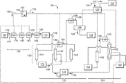
- FIG. 2 illustrates an example of components to implement the processing system 100 to achieve the second concentration of methane in the first product 108 .
- the refrigeration unit 130 can be configured to disperse the refrigerant 132 as a first refrigerant 134 and a second refrigerant 136 .
- the refrigerants 134 , 136 can facilitate thermal transfer at coolers disposed throughout the fluid circuit 106 .
- the coolers can be configured to implement cooling in stages (also, “cooling stages”) to reduce temperature of the process stream 116 .
- Compositions for the refrigerants 134 , 136 can include propylene and ethylene, respectively; however, other compositions may also pose as workable solutions to affect thermal transfer in the coolers.
- the first refrigerant 134 can circulate across one or more coolers (e.g., a first cooler 138 , a second cooler 140 , and a third cooler 142 ).
- the second refrigerant 136 can regulate temperature at coolers at each of the separation unit 120 and the demethanizer unit 124 .
- the units 120 , 124 can be configured to include one or more coolers (e.g., a fourth cooler 144 , a fifth cooler 146 , and a sixth cooler 148 , a seventh cooler 150 ).
- the fluid circuit 106 may include a separator 152 to form vapor, liquid, and mixed phase products.
- the separator 152 can generally be configured as a plurality of vessels (e.g., a first vessel 154 , a second vessel 156 , and a third vessel 158 ).
- the fluid circuit 106 may also include a fourth vessel 160 that couples with a demethanizer column 162 at the demethanizer unit 124 .
- the components 160 , 162 may benefit from use of one or more peripheral components (e.g., a first peripheral component 164 and a second peripheral component 166 ).
- peripheral components 164 , 166 can include pumps, boilers, heaters, and like devices that can facilitate operation of the vessel 160 and/or the demethanizer 162 .
- the second peripheral component 166 may embody a boiler that couples with both the fourth vessel 160 and with the refrigeration unit 130 to condition temperature of the first refrigerant 134 .
- the fluid circuit 106 may couple the vessels 156 , 158 with a flash drum 168 or like vessel.
- the flash drum 168 can couple with the storage facility 112 to provide the first product 108 for storage.
- the fluid circuit 106 may also include one or more throttling devices (e.g., a first throttling device 170 , a second throttling device 172 , and a third throttling device 174 ).
- Examples of the throttling 170 , 172 , 174 can include valves (e.g., Joule-Thompson valves) and/or devices that are similarly situated to throttle the flow of a fluid stream.
- These devices may be interposed between components in the fluid circuit 106 as necessary to achieve certain changes in fluid parameters (e.g., temperature, pressure, etc.). As noted below, the device may provide an expansion stage and a cooling stage, where applicable, to reduce pressure and/or temperature of the process stream 116 .
- FIG. 3 illustrates an example of a mixing unit 200 for use in the processing system 100 of FIGS. 1 and 2 .
- This example can couple with the storage facility 112 , the separation unit 120 , and the demethanizer unit 162 .
- the mixing unit 200 may include a heat exchanger 202 that couples with a compression system 204 .
- the heat exchanger 202 can include cross-flow devices of varying designs (e.g., spiral flow, counter-current flow, distributed flow, etc.), although other devices and designs that can effectively transfer thermal energy may also be desirable.
- the compression system 204 can have one or more compressors (e.g., a first compressor 206 and a second compressor 208 ) and one or more coolers (e.g., a first cooler 210 and a second cooler 212 ).
- the fluid circuit 106 can direct the process stream 116 through the various components to generate the products 108 , 110 .
- the pre-cooling unit 118 can sub-cool the incoming feedstock 102 from a first temperature to a second temperature that is less than the first temperature.
- Incoming feedstock 102 may enter the device (at 176 ) at ambient temperature that prevails at the system 100 and/or surrounding facility.
- the coolers 138 , 140 , 142 can effectively reduce temperature of incoming feedstock 102 by at least about 120° F., with one example being configured to condition the process stream 116 to exit the cooling stages (at 178 ) at approximately ⁇ 40° F.
- the fourth cooler 144 may provide a cooling stage to further reduce temperature of the liquefied ethane stream.
- This cooling stage can reduce temperature of the liquefied ethane stream by at least approximately 10° F., with one example of the fourth cooler 144 being configured so that the liquefied ethane stream exits this cooling stage (at 180 ) at approximately ⁇ 50° F.
- the fluid circuit 106 can direct the liquefied ethane stream to the first throttling device 170 .
- this device can be configured to reduce pressure of the liquefied ethane stream 116 from a first pressure to a second pressure that is less than the first pressure.
- the first pressure may correspond with the super critical pressure for incoming feedstock 102 .
- this super critical pressure may be approximately 800 psig or greater.
- the expansion stage can reduce pressure by at least approximately 700 psig.
- the first expansion unit 170 being configured so that the liquefied ethane stream exits this expansion stage (at 182 ) at approximately 100 psig. Expansion across the first throttling unit 170 may also provide a cooling stage to further lower the temperature of the process stream 108 , e.g., to approximately ⁇ 58° F.
- the fluid circuit 106 can process the liquefied ethane stream at the reduced pressure and reduced temperature to obtain the first product 108 .
- the first product 108 will meet the methane concentration and other specifications for storage. Examples of these processes can form a top product and a bottom product at each of the vessels 154 , 156 , 158 .
- the top product can be in vapor form.
- the bottom product can be in liquid form and/or mixed-phase form (e.g., a combination of liquid and vapor), often depending on temperature and/or pressure of the resulting fluid.
- the fluid circuit 106 can be configured to direct a mixed-phase bottom product from the first vessel 154 to the second vessel 156 .
- the second throttling unit 172 can provide an expansion stage (and a cooling stage) to reduce pressure and temperature and produce a mixed-phase product between the vessels 154 , 156 .
- the mixed-phase product can exit the expansion/cooling stage (at 184 ) at approximately 8 psig and approximately ⁇ 120° F. prior to entry into the second vessel 156 .
- the fluid circuit 106 can be configured to combine the vapor top products from the vessels 154 , 156 upstream of the fifth cooler 146 .
- the fifth cooler 146 can provide a cooling stage so that the combined mixed phase product exits the cooling stage (at 186 ) at approximately ⁇ 138° F. prior to entry into the third vessel 156 .
- the fluid circuit 106 can also combine the bottom product from the vessels 156 , 158 , either in liquid form and/or mixed-phase form, as the process stream 116 .
- the sixth cooler 148 can provide a cooling stage so that the combined mixed phase bottom product exits the cooling stage (at 188 ) at approximately ⁇ 132° F. and approximately 2 psig.
- the fluid circuit 106 can direct the combined liquid bottom product to the flash drum 168 at a reduced temperature and pressure.
- the flash drum 168 can form a liquid product and a vapor product.
- the fluid circuit 106 can direct the liquid product to the storage facility 112 or elsewhere as desired.
- the fluid circuit 106 can direct the vapor product from the flash drum 168 through the heat exchanger 202 . Downstream of the heat exchanger 202 , the fluid circuit 106 can combine the vapor product from the flash drum 168 with incoming return stream 126 , often the boil-off vapor that forms at the storage facility 112 .
- the compressors 206 , 208 and the coolers 210 , 212 can condition temperature and pressure of the combined vapor stream upstream of the heat exchanger 202 .
- the conditioned vapor flows onto the demethanizer column 162 via the heat exchanger 202 .
- processes at the demethanizer column 162 can form a top product and a bottom product, typically in vapor phase and liquid (or mixed) phase, respectively.
- the bottom product exits the demethanizer column 162 to the third throttling device 174 .
- the third throttling device 174 can provide an expansion stage to reduce pressure (and temperature) of this bottom product between the second vessel 156 and the demethanizer column 162 .
- the bottom product can enter the expansion stage (at 190 ) at approximately 470 psig and approximately 57° F. and exit the expansion stage (at 194 ) at approximately 8 psig and approximately ⁇ 114° F. prior to entry into the second vessel 156 .
- the fluid circuit 106 can be configured to recycle the top product from the demethanizer column 162 .
- the seventh cooler 150 may operate as an overhead condenser for the demethanizer column 162 .
- This overhead condenser can provide a cooling stage so that the top product exits the cooling stage (at 196 ) at approximately X ° F.
- the cooled top product enters the fourth vessel 160 , operating here as a reflux drum.
- the fourth vessel 160 can form a top product and a bottom product.
- the pump 164 can pump the liquid bottom product from the fourth vessel 160 back to the demethanizer column 162 .
- the top product can be predominantly methane vapor that exits the system 100 as the second product 110 via the heat exchanger 202 ( FIG. 3 ).
- FIGS. 4, 5, and 6 depict flow diagrams of an exemplary embodiment of a process 300 to prepare incoming liquid ethane (and, generally, feedstock 102 ) for storage.
- the process 300 can include, at stage 302 , distilling an incoming feedstock at a plurality of vessels to form a vapor and a liquid for storage.
- the process 300 can also include, at stage 304 , directing the vapor to a demethanizer column and, at stage 306 , circulating liquid from the demethanizer back to the plurality of vessels.
- the process 300 can also include, at stage 308 , cooling the incoming feedstock upstream of the plurality of vessels and, at stage 310 , throttling flow of the incoming feedstock upstream of the plurality of vessels.
- stage 302 in the process 300 can incorporate various stages to distill the incoming feedstock, as desired.
- these stages may include, at stage 312 , forming a first top product and a first bottom product from the incoming feedstock in a first vessel.
- the stages may also include, at stage 314 , directing the first bottom product and the liquid from the demethanizer column to a second vessel and, at stage 316 , separating the first bottom product into a second top product and a second bottom product in the second vessel.
- the stages may further include, at stage 318 , mixing the first top product with the second top product upstream of a third vessel, at stage 320 , cooling the first top product and the second top product upstream of the third vessel, and, at stage 322 , forming a third bottom product from the first top product and the second top product in the third vessel.
Abstract
Description
Claims (8)
Priority Applications (8)
| Application Number | Priority Date | Filing Date | Title |
|---|---|---|---|
| US14/974,602 US10928128B2 (en) | 2015-05-04 | 2015-12-18 | Preparing hydrocarbon streams for storage |
| MX2017014105A MX2017014105A (en) | 2015-05-04 | 2016-04-08 | Preparing hydrocarbon streams for storage. |
| CA2984144A CA2984144C (en) | 2015-05-04 | 2016-04-08 | Preparing hydrocarbon streams for storage |
| EP16724489.6A EP3292363A2 (en) | 2015-05-04 | 2016-04-08 | Preparing hydrocarbon streams for storage |
| CN201680025950.7A CN107548446A (en) | 2015-05-04 | 2016-04-08 | Prepare the hydrocarbon stream for storage |
| PCT/US2016/026616 WO2016178792A2 (en) | 2015-05-04 | 2016-04-08 | Preparing hydrocarbon streams for storage |
| AU2016259235A AU2016259235B2 (en) | 2015-05-04 | 2016-04-08 | Preparing hydrocarbon streams for storage |
| US17/178,613 US20210172676A1 (en) | 2015-05-04 | 2021-02-18 | Preparing hydrocarbon streams for storage |
Applications Claiming Priority (2)
| Application Number | Priority Date | Filing Date | Title |
|---|---|---|---|
| US201562156664P | 2015-05-04 | 2015-05-04 | |
| US14/974,602 US10928128B2 (en) | 2015-05-04 | 2015-12-18 | Preparing hydrocarbon streams for storage |
Related Child Applications (1)
| Application Number | Title | Priority Date | Filing Date |
|---|---|---|---|
| US17/178,613 Division US20210172676A1 (en) | 2015-05-04 | 2021-02-18 | Preparing hydrocarbon streams for storage |
Publications (2)
| Publication Number | Publication Date |
|---|---|
| US20160327336A1 US20160327336A1 (en) | 2016-11-10 |
| US10928128B2 true US10928128B2 (en) | 2021-02-23 |
Family
ID=56069191
Family Applications (2)
| Application Number | Title | Priority Date | Filing Date |
|---|---|---|---|
| US14/974,602 Active 2037-06-28 US10928128B2 (en) | 2015-05-04 | 2015-12-18 | Preparing hydrocarbon streams for storage |
| US17/178,613 Pending US20210172676A1 (en) | 2015-05-04 | 2021-02-18 | Preparing hydrocarbon streams for storage |
Family Applications After (1)
| Application Number | Title | Priority Date | Filing Date |
|---|---|---|---|
| US17/178,613 Pending US20210172676A1 (en) | 2015-05-04 | 2021-02-18 | Preparing hydrocarbon streams for storage |
Country Status (7)
| Country | Link |
|---|---|
| US (2) | US10928128B2 (en) |
| EP (1) | EP3292363A2 (en) |
| CN (1) | CN107548446A (en) |
| AU (1) | AU2016259235B2 (en) |
| CA (1) | CA2984144C (en) |
| MX (1) | MX2017014105A (en) |
| WO (1) | WO2016178792A2 (en) |
Families Citing this family (3)
| Publication number | Priority date | Publication date | Assignee | Title |
|---|---|---|---|---|
| US10330382B2 (en) | 2016-05-18 | 2019-06-25 | Fluor Technologies Corporation | Systems and methods for LNG production with propane and ethane recovery |
| US11725879B2 (en) | 2016-09-09 | 2023-08-15 | Fluor Technologies Corporation | Methods and configuration for retrofitting NGL plant for high ethane recovery |
| MX2020003412A (en) | 2017-10-20 | 2020-09-18 | Fluor Tech Corp | Phase implementation of natural gas liquid recovery plants. |
Citations (33)
| Publication number | Priority date | Publication date | Assignee | Title |
|---|---|---|---|---|
| US1043731A (en) | 1910-11-11 | 1912-11-05 | Frederick Royle | Manufacture of felt and like hats. |
| GB857587A (en) | 1956-05-28 | 1961-01-04 | Exxon Research Engineering Co | Method of making hydrogen and uses thereof |
| US3675435A (en) * | 1969-11-07 | 1972-07-11 | Fluor Corp | Low pressure ethylene recovery process |
| US3729944A (en) | 1970-07-23 | 1973-05-01 | Phillips Petroleum Co | Separation of gases |
| US4061481A (en) | 1974-10-22 | 1977-12-06 | The Ortloff Corporation | Natural gas processing |
| US4155729A (en) * | 1977-10-20 | 1979-05-22 | Phillips Petroleum Company | Liquid flash between expanders in gas separation |
| US4171964A (en) | 1976-06-21 | 1979-10-23 | The Ortloff Corporation | Hydrocarbon gas processing |
| US4225329A (en) * | 1979-02-12 | 1980-09-30 | Phillips Petroleum Company | Natural gas liquefaction with nitrogen rejection stabilization |
| US4435198A (en) * | 1982-02-24 | 1984-03-06 | Phillips Petroleum Company | Separation of nitrogen from natural gas |
| CN1043731A (en) | 1988-11-21 | 1990-07-11 | 埃尔科公司 | The processing treatment of hydrocarbon gas |
| US5600969A (en) | 1995-12-18 | 1997-02-11 | Phillips Petroleum Company | Process and apparatus to produce a small scale LNG stream from an existing NGL expander plant demethanizer |
| US5675054A (en) | 1995-07-17 | 1997-10-07 | Manley; David | Low cost thermal coupling in ethylene recovery |
| US6105391A (en) * | 1997-12-22 | 2000-08-22 | Institut Francais Du Petrole | Process for liquefying a gas, notably a natural gas or air, comprising a medium pressure drain and application |
| US6526777B1 (en) | 2001-04-20 | 2003-03-04 | Elcor Corporation | LNG production in cryogenic natural gas processing plants |
| US20040206112A1 (en) | 2002-05-08 | 2004-10-21 | John Mak | Configuration and process for ngli recovery using a subcooled absorption reflux process |
| US6915662B2 (en) | 2000-10-02 | 2005-07-12 | Elkcorp. | Hydrocarbon gas processing |
| US20060004242A1 (en) | 2004-07-02 | 2006-01-05 | Kellogg Brown & Root, Inc. | Low pressure olefin recovery process |
| US20080072620A1 (en) | 2001-09-13 | 2008-03-27 | Runbalk David B | Treating of a crude containing natural gas |
| CN101283078A (en) | 2005-09-15 | 2008-10-08 | 冷能源有限公司 | Process and apparatus for removal of sour species from a natural gas stream |
| US7484385B2 (en) | 2003-01-16 | 2009-02-03 | Lummus Technology Inc. | Multiple reflux stream hydrocarbon recovery process |
| CN101539364A (en) | 2009-04-17 | 2009-09-23 | 上海惠生化工工程有限公司 | Pyrolysis gas compression system improvement technique featuring light dydrocarbon sequential separation procedure |
| US7713497B2 (en) | 2002-08-15 | 2010-05-11 | Fluor Technologies Corporation | Low pressure NGL plant configurations |
| CN103058188A (en) | 2012-12-31 | 2013-04-24 | 安庆凯美特气体有限公司 | Method for reducing carbon dioxide discharge amount in food-grade liquid carbon dioxide product production |
| WO2014006178A1 (en) | 2012-07-05 | 2014-01-09 | Technip France | Process for producing treated natural gas, a c3 + hydrocarbon-rich fraction and optionally an ethane-rich stream, and associated apparatus |
| CN103542693A (en) | 2012-07-12 | 2014-01-29 | 中国石油天然气股份有限公司 | Ethylene cryogenic separation method for large-sized ethylene device |
| US8707730B2 (en) | 2009-12-07 | 2014-04-29 | Alkane, Llc | Conditioning an ethane-rich stream for storage and transportation |
| CN103776236A (en) | 2014-02-25 | 2014-05-07 | 合肥美菱股份有限公司 | Refrigerator food freshness segmentation reminding system and application thereof |
| CN103822438A (en) | 2012-11-16 | 2014-05-28 | 中国石油天然气股份有限公司 | Shallow condensing light hydrocarbon recovery technique |
| EP2749830A1 (en) | 2012-12-27 | 2014-07-02 | Shell Internationale Research Maatschappij B.V. | Method for the manufacture of conditioned ethane and an apparatus therefor |
| CN203837413U (en) | 2014-05-09 | 2014-09-17 | 中国石油集团工程设计有限责任公司 | Device for extracting ethane and hydrocarbon mixture from natural gas |
| CN204298357U (en) | 2014-08-19 | 2015-04-29 | 中国海洋石油总公司 | A kind of oxygen-containing coal bed gas deoxidation, denitrogenation and liquefaction system |
| CN204310982U (en) | 2014-11-21 | 2015-05-06 | 中国石油天然气股份有限公司 | Defective carbon two recovery system and ethylene separation device |
| CN204757540U (en) | 2015-07-07 | 2015-11-11 | 安徽倍卓众一化工工程技术有限公司 | BOG purifies liquefaction recovery unit |
Family Cites Families (5)
| Publication number | Priority date | Publication date | Assignee | Title |
|---|---|---|---|---|
| US3319429A (en) * | 1965-11-22 | 1967-05-16 | Air Prod & Chem | Methods for separating mixtures of normally gaseous materials |
| US4507133A (en) * | 1983-09-29 | 1985-03-26 | Exxon Production Research Co. | Process for LPG recovery |
| US6662589B1 (en) * | 2003-04-16 | 2003-12-16 | Air Products And Chemicals, Inc. | Integrated high pressure NGL recovery in the production of liquefied natural gas |
| US8627681B2 (en) * | 2009-03-04 | 2014-01-14 | Lummus Technology Inc. | Nitrogen removal with iso-pressure open refrigeration natural gas liquids recovery |
| DE102012020469A1 (en) * | 2012-10-18 | 2014-04-24 | Linde Aktiengesellschaft | Method for separating methane from methane-containing synthesis gas in separation unit, involves feeding capacitor with secondary portion of refrigerant of outlet temperature to intermediate temperature and cooling to lower temperature |
-
2015
- 2015-12-18 US US14/974,602 patent/US10928128B2/en active Active
-
2016
- 2016-04-08 AU AU2016259235A patent/AU2016259235B2/en active Active
- 2016-04-08 CN CN201680025950.7A patent/CN107548446A/en active Pending
- 2016-04-08 CA CA2984144A patent/CA2984144C/en active Active
- 2016-04-08 EP EP16724489.6A patent/EP3292363A2/en active Pending
- 2016-04-08 WO PCT/US2016/026616 patent/WO2016178792A2/en active Application Filing
- 2016-04-08 MX MX2017014105A patent/MX2017014105A/en unknown
-
2021
- 2021-02-18 US US17/178,613 patent/US20210172676A1/en active Pending
Patent Citations (35)
| Publication number | Priority date | Publication date | Assignee | Title |
|---|---|---|---|---|
| US1043731A (en) | 1910-11-11 | 1912-11-05 | Frederick Royle | Manufacture of felt and like hats. |
| GB857587A (en) | 1956-05-28 | 1961-01-04 | Exxon Research Engineering Co | Method of making hydrogen and uses thereof |
| US3675435A (en) * | 1969-11-07 | 1972-07-11 | Fluor Corp | Low pressure ethylene recovery process |
| US3729944A (en) | 1970-07-23 | 1973-05-01 | Phillips Petroleum Co | Separation of gases |
| US4061481B1 (en) | 1974-10-22 | 1985-03-19 | ||
| US4061481A (en) | 1974-10-22 | 1977-12-06 | The Ortloff Corporation | Natural gas processing |
| US4171964A (en) | 1976-06-21 | 1979-10-23 | The Ortloff Corporation | Hydrocarbon gas processing |
| US4155729A (en) * | 1977-10-20 | 1979-05-22 | Phillips Petroleum Company | Liquid flash between expanders in gas separation |
| US4225329A (en) * | 1979-02-12 | 1980-09-30 | Phillips Petroleum Company | Natural gas liquefaction with nitrogen rejection stabilization |
| US4435198A (en) * | 1982-02-24 | 1984-03-06 | Phillips Petroleum Company | Separation of nitrogen from natural gas |
| CN1043731A (en) | 1988-11-21 | 1990-07-11 | 埃尔科公司 | The processing treatment of hydrocarbon gas |
| US5675054A (en) | 1995-07-17 | 1997-10-07 | Manley; David | Low cost thermal coupling in ethylene recovery |
| US5600969A (en) | 1995-12-18 | 1997-02-11 | Phillips Petroleum Company | Process and apparatus to produce a small scale LNG stream from an existing NGL expander plant demethanizer |
| US6105391A (en) * | 1997-12-22 | 2000-08-22 | Institut Francais Du Petrole | Process for liquefying a gas, notably a natural gas or air, comprising a medium pressure drain and application |
| US6915662B2 (en) | 2000-10-02 | 2005-07-12 | Elkcorp. | Hydrocarbon gas processing |
| US6526777B1 (en) | 2001-04-20 | 2003-03-04 | Elcor Corporation | LNG production in cryogenic natural gas processing plants |
| US20080072620A1 (en) | 2001-09-13 | 2008-03-27 | Runbalk David B | Treating of a crude containing natural gas |
| US20040206112A1 (en) | 2002-05-08 | 2004-10-21 | John Mak | Configuration and process for ngli recovery using a subcooled absorption reflux process |
| US7713497B2 (en) | 2002-08-15 | 2010-05-11 | Fluor Technologies Corporation | Low pressure NGL plant configurations |
| US7484385B2 (en) | 2003-01-16 | 2009-02-03 | Lummus Technology Inc. | Multiple reflux stream hydrocarbon recovery process |
| US7793517B2 (en) * | 2003-01-16 | 2010-09-14 | Lummus Technology Inc. | Multiple reflux stream hydrocarbon recovery process |
| US20060004242A1 (en) | 2004-07-02 | 2006-01-05 | Kellogg Brown & Root, Inc. | Low pressure olefin recovery process |
| CN101283078A (en) | 2005-09-15 | 2008-10-08 | 冷能源有限公司 | Process and apparatus for removal of sour species from a natural gas stream |
| CN101539364A (en) | 2009-04-17 | 2009-09-23 | 上海惠生化工工程有限公司 | Pyrolysis gas compression system improvement technique featuring light dydrocarbon sequential separation procedure |
| US8707730B2 (en) | 2009-12-07 | 2014-04-29 | Alkane, Llc | Conditioning an ethane-rich stream for storage and transportation |
| WO2014006178A1 (en) | 2012-07-05 | 2014-01-09 | Technip France | Process for producing treated natural gas, a c3 + hydrocarbon-rich fraction and optionally an ethane-rich stream, and associated apparatus |
| CN103542693A (en) | 2012-07-12 | 2014-01-29 | 中国石油天然气股份有限公司 | Ethylene cryogenic separation method for large-sized ethylene device |
| CN103822438A (en) | 2012-11-16 | 2014-05-28 | 中国石油天然气股份有限公司 | Shallow condensing light hydrocarbon recovery technique |
| EP2749830A1 (en) | 2012-12-27 | 2014-07-02 | Shell Internationale Research Maatschappij B.V. | Method for the manufacture of conditioned ethane and an apparatus therefor |
| CN103058188A (en) | 2012-12-31 | 2013-04-24 | 安庆凯美特气体有限公司 | Method for reducing carbon dioxide discharge amount in food-grade liquid carbon dioxide product production |
| CN103776236A (en) | 2014-02-25 | 2014-05-07 | 合肥美菱股份有限公司 | Refrigerator food freshness segmentation reminding system and application thereof |
| CN203837413U (en) | 2014-05-09 | 2014-09-17 | 中国石油集团工程设计有限责任公司 | Device for extracting ethane and hydrocarbon mixture from natural gas |
| CN204298357U (en) | 2014-08-19 | 2015-04-29 | 中国海洋石油总公司 | A kind of oxygen-containing coal bed gas deoxidation, denitrogenation and liquefaction system |
| CN204310982U (en) | 2014-11-21 | 2015-05-06 | 中国石油天然气股份有限公司 | Defective carbon two recovery system and ethylene separation device |
| CN204757540U (en) | 2015-07-07 | 2015-11-11 | 安徽倍卓众一化工工程技术有限公司 | BOG purifies liquefaction recovery unit |
Non-Patent Citations (2)
| Title |
|---|
| PCT Invitation to Pay Additional Fees issued in connection with corresponding PCT Application No. PCT/US2016/026616 dated Aug. 1, 2016. |
| PCT Search Report and Written Opinion issued in connection with corresponding PCT Application No. PCT/US2016/026616 dated Nov. 3, 2016. |
Also Published As
| Publication number | Publication date |
|---|---|
| CN107548446A (en) | 2018-01-05 |
| MX2017014105A (en) | 2018-03-01 |
| AU2016259235B2 (en) | 2021-09-23 |
| US20210172676A1 (en) | 2021-06-10 |
| CA2984144A1 (en) | 2016-11-10 |
| AU2016259235A1 (en) | 2017-11-09 |
| US20160327336A1 (en) | 2016-11-10 |
| WO2016178792A3 (en) | 2016-12-15 |
| EP3292363A2 (en) | 2018-03-14 |
| CA2984144C (en) | 2023-08-29 |
| WO2016178792A2 (en) | 2016-11-10 |
Similar Documents
| Publication | Publication Date | Title |
|---|---|---|
| US20210172676A1 (en) | Preparing hydrocarbon streams for storage | |
| US11760462B2 (en) | Boil-off gas re-liquefying device and method for ship | |
| US10017701B2 (en) | Flare elimination process and methods of use | |
| US10323880B2 (en) | Mixed refrigerant cooling process and system | |
| AU2019326291B2 (en) | Managing make-up gas composition variation for a high pressure expander process | |
| US20190101328A1 (en) | Natural Gas Liquefaction by a High Pressure Expansion Process | |
| AU2023200787A1 (en) | Gas liquefaction system and methods | |
| AU2023200283A1 (en) | Gas liquefaction system and methods | |
| RU2720732C1 (en) | Method and system for cooling and separating hydrocarbon flow | |
| AU2015252986B2 (en) | Liquid drains in core-in-shell heat exchanger | |
| CA3076605C (en) | Natural gas liquefaction by a high pressure expansion process | |
| AU2017200185B2 (en) | Reducing refrigeration duty on a refrigeration unit in a gas processing system | |
| US20220316796A1 (en) | Method Of Cooling Boil Off Gas And An Apparatus Therefor |
Legal Events
| Date | Code | Title | Description |
|---|---|---|---|
| AS | Assignment |
Owner name: GE OIL & GAS, INC., TEXAS Free format text: ASSIGNMENT OF ASSIGNORS INTEREST;ASSIGNORS:KENNEDY, DAVID ALLEN;SALAMON, MARK MULHERIN;YOUNT, CHRISTOPHER SCOTT;SIGNING DATES FROM 20151217 TO 20151218;REEL/FRAME:037330/0639 |
|
| STPP | Information on status: patent application and granting procedure in general |
Free format text: FINAL REJECTION MAILED |
|
| STPP | Information on status: patent application and granting procedure in general |
Free format text: DOCKETED NEW CASE - READY FOR EXAMINATION |
|
| STPP | Information on status: patent application and granting procedure in general |
Free format text: NON FINAL ACTION MAILED |
|
| STPP | Information on status: patent application and granting procedure in general |
Free format text: RESPONSE TO NON-FINAL OFFICE ACTION ENTERED AND FORWARDED TO EXAMINER |
|
| STPP | Information on status: patent application and granting procedure in general |
Free format text: FINAL REJECTION MAILED |
|
| STPP | Information on status: patent application and granting procedure in general |
Free format text: RESPONSE AFTER FINAL ACTION FORWARDED TO EXAMINER |
|
| STPP | Information on status: patent application and granting procedure in general |
Free format text: DOCKETED NEW CASE - READY FOR EXAMINATION |
|
| STCF | Information on status: patent grant |
Free format text: PATENTED CASE |