US10923982B2 - Electric compressor motor housing, and vehicle-mounted electric compressor employing same - Google Patents
Electric compressor motor housing, and vehicle-mounted electric compressor employing same Download PDFInfo
- Publication number
- US10923982B2 US10923982B2 US15/558,129 US201615558129A US10923982B2 US 10923982 B2 US10923982 B2 US 10923982B2 US 201615558129 A US201615558129 A US 201615558129A US 10923982 B2 US10923982 B2 US 10923982B2
- Authority
- US
- United States
- Prior art keywords
- motor housing
- ribs
- compressor
- main body
- electric compressor
- Prior art date
- Legal status (The legal status is an assumption and is not a legal conclusion. Google has not performed a legal analysis and makes no representation as to the accuracy of the status listed.)
- Active, expires
Links
Images


Classifications
-
- H—ELECTRICITY
- H02—GENERATION; CONVERSION OR DISTRIBUTION OF ELECTRIC POWER
- H02K—DYNAMO-ELECTRIC MACHINES
- H02K5/00—Casings; Enclosures; Supports
- H02K5/04—Casings or enclosures characterised by the shape, form or construction thereof
-
- F—MECHANICAL ENGINEERING; LIGHTING; HEATING; WEAPONS; BLASTING
- F04—POSITIVE - DISPLACEMENT MACHINES FOR LIQUIDS; PUMPS FOR LIQUIDS OR ELASTIC FLUIDS
- F04B—POSITIVE-DISPLACEMENT MACHINES FOR LIQUIDS; PUMPS
- F04B35/00—Piston pumps specially adapted for elastic fluids and characterised by the driving means to their working members, or by combination with, or adaptation to, specific driving engines or motors, not otherwise provided for
- F04B35/04—Piston pumps specially adapted for elastic fluids and characterised by the driving means to their working members, or by combination with, or adaptation to, specific driving engines or motors, not otherwise provided for the means being electric
-
- F—MECHANICAL ENGINEERING; LIGHTING; HEATING; WEAPONS; BLASTING
- F04—POSITIVE - DISPLACEMENT MACHINES FOR LIQUIDS; PUMPS FOR LIQUIDS OR ELASTIC FLUIDS
- F04B—POSITIVE-DISPLACEMENT MACHINES FOR LIQUIDS; PUMPS
- F04B39/00—Component parts, details, or accessories, of pumps or pumping systems specially adapted for elastic fluids, not otherwise provided for in, or of interest apart from, groups F04B25/00 - F04B37/00
- F04B39/06—Cooling; Heating; Prevention of freezing
-
- F—MECHANICAL ENGINEERING; LIGHTING; HEATING; WEAPONS; BLASTING
- F04—POSITIVE - DISPLACEMENT MACHINES FOR LIQUIDS; PUMPS FOR LIQUIDS OR ELASTIC FLUIDS
- F04B—POSITIVE-DISPLACEMENT MACHINES FOR LIQUIDS; PUMPS
- F04B39/00—Component parts, details, or accessories, of pumps or pumping systems specially adapted for elastic fluids, not otherwise provided for in, or of interest apart from, groups F04B25/00 - F04B37/00
- F04B39/12—Casings; Cylinders; Cylinder heads; Fluid connections
- F04B39/121—Casings
-
- H—ELECTRICITY
- H02—GENERATION; CONVERSION OR DISTRIBUTION OF ELECTRIC POWER
- H02K—DYNAMO-ELECTRIC MACHINES
- H02K11/00—Structural association of dynamo-electric machines with electric components or with devices for shielding, monitoring or protection
- H02K11/30—Structural association with control circuits or drive circuits
- H02K11/33—Drive circuits, e.g. power electronics
-
- H—ELECTRICITY
- H02—GENERATION; CONVERSION OR DISTRIBUTION OF ELECTRIC POWER
- H02K—DYNAMO-ELECTRIC MACHINES
- H02K5/00—Casings; Enclosures; Supports
- H02K5/04—Casings or enclosures characterised by the shape, form or construction thereof
- H02K5/18—Casings or enclosures characterised by the shape, form or construction thereof with ribs or fins for improving heat transfer
-
- H—ELECTRICITY
- H02—GENERATION; CONVERSION OR DISTRIBUTION OF ELECTRIC POWER
- H02K—DYNAMO-ELECTRIC MACHINES
- H02K5/00—Casings; Enclosures; Supports
- H02K5/04—Casings or enclosures characterised by the shape, form or construction thereof
- H02K5/20—Casings or enclosures characterised by the shape, form or construction thereof with channels or ducts for flow of cooling medium
- H02K5/203—Casings or enclosures characterised by the shape, form or construction thereof with channels or ducts for flow of cooling medium specially adapted for liquids, e.g. cooling jackets
-
- H—ELECTRICITY
- H02—GENERATION; CONVERSION OR DISTRIBUTION OF ELECTRIC POWER
- H02K—DYNAMO-ELECTRIC MACHINES
- H02K5/00—Casings; Enclosures; Supports
- H02K5/04—Casings or enclosures characterised by the shape, form or construction thereof
- H02K5/22—Auxiliary parts of casings not covered by groups H02K5/06-H02K5/20, e.g. shaped to form connection boxes or terminal boxes
-
- H—ELECTRICITY
- H02—GENERATION; CONVERSION OR DISTRIBUTION OF ELECTRIC POWER
- H02K—DYNAMO-ELECTRIC MACHINES
- H02K9/00—Arrangements for cooling or ventilating
-
- H02K9/005—
-
- H—ELECTRICITY
- H02—GENERATION; CONVERSION OR DISTRIBUTION OF ELECTRIC POWER
- H02K—DYNAMO-ELECTRIC MACHINES
- H02K9/00—Arrangements for cooling or ventilating
- H02K9/08—Arrangements for cooling or ventilating by gaseous cooling medium circulating wholly within the machine casing
Definitions
- the present invention relates to an electric compressor motor housing in which an inverter circuit that drives a motor is integrally incorporated; and an inverter-integrated vehicle-mounted electric compressor in which the inverter circuit is integrally incorporated by using the motor housing.
- an inverter-integrated vehicle-mounted electric compressor As a vehicle-mounted electric compressor used for a vehicular air conditioning device, an inverter-integrated vehicle-mounted electric compressor has been known.
- Such an inverter-integrated vehicle-mounted electric compressor includes an inverter accommodating portion on an outer periphery of a housing that includes a motor and a compressor.
- an inverter circuit that drives the motor is accommodated and installed, whereby the inverter circuit is incorporated integrally with the compressor.
- the housing that is the outline of the vehicle-mounted electric compressor is configured by integrally coupling a motor housing that includes the motor to a compressor housing that includes the compressor.
- Patent Document 1 discloses an example in which an inverter accommodating portion, in which an inverter circuit is accommodated and installed, is provided in an upper portion (upper surface) of the outer periphery on the motor housing.
- the vehicle-mounted electric compressor further includes compressor attachment feet for installing the electric compressor to a vehicle.
- the compressor attachment feet are provided in a plurality of locations in an upper portion (upper surface) and a lower portion (lower surface) of the outer periphery on the motor housing.
- the vehicle-mounted electric compressor includes an intake port for a low-pressure refrigerant gas provided on a side surface on the rear end portion of the motor housing, and a discharge port for a high-pressure refrigerant gas on an outer peripheral side portion of the compressor housing.
- Patent Documents 1 to 3 each disclose an example in which a plurality of refrigerant passages are provided around cylindrical space that includes a motor in the motor housing in the direction of the motor axis.
- the electric compressor motor housing in the example is configured to guide a low-pressure refrigerant gas introduced from a refrigerant intake port to inside the rear end portion of the motor housing through the refrigerant passages, toward the motor housing.
- This configuration can cool a motor and components (heat-releasing components, in particular) of an inverter circuit accommodated and installed in an inverter accommodating portion on an outer periphery of the motor housing.
- Patent Document 1 Japanese Unexamined Patent Application Publication No. 2014-165944A
- Patent Document 2 Japanese Unexamined Patent Application Publication No. 2013-106365A
- Patent Document 3 Japanese Unexamined Patent Application Publication No. 2006-197785A
- the motor housing is configured such that the inverter accommodating portion is provided in the upper portion of the outer periphery on the motor housing.
- the motor housing is further configured such that the compressor attachment feet for installing the electric compressor to a vehicle are also provided in a plurality of locations in the upper portion and the lower portion of the outer periphery on the motor housing. Therefore, the rigidity in the upper portion (upper surface) and the lower portion (lower surface) is ensured sufficiently.
- the rigidity in both side portions needs to be ensured by only a thickness of a housing wall. If the wall thickness is reduced, the rigidity on both side portions (both side surfaces) is insufficient and thus the housing in a tubular shape is deformed and crushed in the vertical direction, thereby unfortunately sometimes generating vibration and noise.
- the inverter accommodating portion provided in the upper portion of the outer periphery of the motor housing is sometimes defined to have a larger width than that of the main body portion of the motor housing.
- Heat-releasing components included in the inverter circuit are cooled by releasing the heat from the components to the refrigerant flowing through the refrigerant passages via the inverter accommodating portion and a wall portion (heat transfer portion) of the motor housing.
- the heat-releasing components are accommodated and installed in the larger wide portion, the heat-releasing is restricted by the thickness of the wall portion, thereby reducing cross-sectional area of the heat transfer portion, and increasing heat-passing resistance. This leads to insufficient cooling effect, whereby performance is liable to be degraded due to the heat released from the components.
- an object of the present invention is to provide an electric compressor motor housing in which rigidity of a motor housing main body is increased and deformation thereof is suppressed, thereby reducing vibration and noise and increasing cooling performance of components of the inverter circuit, whereby performance degradation caused by the heat release is suppressed and reliability is increased; and a vehicle-mounted electric compressor employing the electric compressor motor housing.
- the electric compressor motor housing and the vehicle-mounted electric compressor employing the electric compressor motor housing of the present invention adopt the following means in order to solve the problems described above.
- An electric compressor motor housing includes a motor housing main body, one end of which is an opening portion capable of coupling to a compressor housing, and the interior of which is a cylindrical space for including a motor.
- the electric compressor motor housing further includes a plurality of refrigerant passages formed around the cylindrical space in the motor housing main body in the direction of the motor axis.
- the electric compressor motor housing further includes an inverter accommodating portion provided in an upper portion of the outer periphery of the motor housing main body, in which an inverter circuit that drives the motor is accommodated and installed.
- the electric compressor motor housing further includes compressor attachment feet provided in a plurality of locations in upper and lower portions of the outer periphery of the motor housing main body.
- the electric compressor motor housing includes a refrigerant intake port provided on a side surface on the rear end portion of the motor housing main body and communicated with the internal space thereof.
- a refrigerant intake port provided on a side surface on the rear end portion of the motor housing main body and communicated with the internal space thereof.
- One or more lines of ribs are provided on the outer peripheral side surface of the motor housing main body, protruding outward and extending in the vertical direction.
- the electric compressor motor housing includes the motor housing main body, the interior of which is the cylindrical space for including the motor, and in which the refrigerant passages are formed around the cylindrical space, in a direction of a motor axis.
- the electric compressor motor housing further includes the inverter accommodating portion provided in the upper portion of the outer periphery of the motor housing main body.
- the electric compressor motor housing further includes the compressor attachment feet provided in a plurality of locations in upper and lower portions of the outer periphery of the motor housing main body, and the refrigerant intake port provided on the side surface on the rear end portion of the motor housing main body.
- One or more lines of the ribs are provided on the outer peripheral side surface of the motor housing main body, protruding outward and extending in the vertical direction. That is, the one or more lines of ribs protruding outward and extending in the vertical direction are provided on the outer peripheral side portion (side surface) of the motor housing main body where the rigidity is often insufficient. In contrast, the upper portion (upper surface) and the lower portion (lower surface) of the outer periphery of the motor housing main body is ensured to have sufficient rigidity because the inverter accommodating portion and the compressor attachment feet are provided thereon.
- the ribs can thus increase the rigidity of the motor housing main body without increasing the wall thickness of the entire housing.
- the ribs increase the cross-sectional area of a wall portion (heat transfer portion) coupling the outer peripheral side portion of the motor housing main body to the inverter accommodating portion provided in an upper portion of the outer periphery of the motor housing main body.
- This configuration can increase the area of a radiating surface for heat transfer from the inverter accommodating portion to the refrigerant flowing through the refrigerant passages inside the motor housing main body.
- This configuration can therefore increase the rigidity of the motor housing and suppress deformation thereof, thereby reducing vibration and noise.
- this configuration can increase cooling performance of components of the inverter circuit accommodated and installed in the inverter accommodating portion. This suppresses performance degradation caused by heat release from the components, and increases the reliability.
- ribs are provided in at least one line for each of the positions corresponding to the installation positions of a condenser and a coil included in the inverter circuit accommodated and installed along one side of the inverter accommodating portion.
- At least one line of the ribs is provided for each of the positions corresponding to the installation positions of the condenser and the coil included in the inverter circuit accommodated and installed along one side of the inverter accommodating portion.
- the cross-sectional area of the heat transfer portion (wall portion) is increased by the ribs provided on the positions corresponding to the installation positions of the condenser and the coil. Therefore, even if the condenser and the coil included in the filter circuit of the inverter circuit are accommodated and installed along one side of the inverter accommodating portion, the heat from the condenser and the coil can be released to the refrigerant flowing through the refrigerant passages inside the motor housing main body via the heat transfer portion (wall portion).
- this configuration achieves the following effect in addition to increasing the rigidity of the motor housing to reduce vibration and noise. That is, the configuration can also ensure the cooling performance of the condenser and the coil included in the filter circuit of the inverter circuit, thereby suppressing performance degradation caused by the heat released from the components. Furthermore, the configuration can increase the flexibility of layout of the components included in the filter circuit.
- At least one of the ribs is provided in the vicinity of and along the mating surface of the opening portion capable of coupling to the compressor housing.
- At least one of the ribs is provided in the vicinity of and along the mating surface of the opening portion capable of coupling to the compressor housing. Therefore, when the electric compressor is mounted on a vehicle and if rainwater is scattered from a road surface to a side surface of the motor housing main body while driving, or a cleaning fluid enters there while washing, this configuration can prevent the rainwater or cleaning fluid and the like from reaching the mating surface between the motor housing main body and the compressor housing, because of the rib provided along the mating surface. Therefore, this configuration achieves the following effect in addition to increasing the rigidity of the motor housing to reduce vibration and noise, and increasing cooling performance of components of the inverter circuit, thereby suppressing performance degradation caused by the heat released from the components. That is, the configuration can further increase corrosion resistance of a seal member and the like provided on the mating surface between the motor housing and the compressor housing.
- one or more lines of the ribs are provided on one side portion of the motor housing main body.
- the height of protrusion of the ribs is defined same as the height of a side surface of the inverter accommodating portion, thereby forming a flat surface flush with the side surface of the inverter accommodating portion.
- one or more lines of the ribs are provided on one side surface of the motor housing main body.
- the height of protrusion of the ribs is defined same as the height of a side surface of the inverter accommodating portion, thereby forming a flat surface flush with the side surface of the inverter accommodating portion. Therefore, when handling the electric compressor, the electric compressor can be placed in a stable manner with the flat surface formed on the side surface of the motor housing main body facing down. Therefore, this configuration achieves the following effect in addition to increasing the rigidity of the motor housing to reduce vibration and noise, and increasing cooling performance of components of the inverter circuit, thereby suppressing performance degradation caused by the heat released from the components. That is, the configuration can also facilitate handling when incorporating the electric compressor to a vehicle.
- one or more lines of the ribs are provided on the side surface same as the side surface on which the refrigerant intake port on the motor housing main body is provided.
- the height of outward protrusion of the ribs is defined higher than the positions of a seat surface of the refrigerant intake port and a seat surface of the compressor attachment feet.
- one or more lines of the ribs are provided on the side surface same as the side surface on which the refrigerant intake port on the motor housing main body is provided.
- the height of outward protrusion of the ribs is defined higher than the positions of the seat surface of the refrigerant intake port and the seat surface of the compressor attachment feet. This configuration can prevent the seat surfaces from being damaged because the height of protrusion of the ribs is defined higher than the seat surfaces. This effect is achieved when placing the motor housing with the side surface facing down on which the seat surface of the refrigerant intake port and the seat surface of the compressor attachment feet are provided. The effect is also achieved when other articles come into contact with the side surface.
- this configuration achieves the following effect in addition to increasing the rigidity of the motor housing to reduce vibration and noise, and increasing cooling performance of components of the inverter circuit, thereby suppressing performance degradation caused by the heat released from the components. That is, the configuration can also eliminate refrigerant leakage or faulty installation of the electric compressor caused by damage to the seat surface or the seat surface, for example.
- one or more lines of the ribs are provided on the side surface same as the side surface on which the refrigerant intake port on the motor housing main body is provided.
- the height of outward protrusion of the ribs is defined higher than the height of outward protrusion on the side surface of the inverter accommodating portion.
- this configuration achieves the following effect in addition to increasing the rigidity of the motor housing to reduce vibration and noise, and increasing cooling performance of components of the inverter circuit, thereby suppressing performance degradation caused by the heat released from the components. That is, the configuration can also prevent a high-voltage short circuit caused by damage to the inverter accommodating portion if the vehicle is involved in a collision accident, and suppress expansion of the accident.
- the inverter circuit is integrally incorporated in the housing including the motor and the compressor.
- an opening portion at one end thereof is coupled to the compressor housing including the compressor. That is, the vehicle-mounted electric compressor is configured such that the inverter circuit is integrally incorporated in the housing including the motor and the compressor.
- This configuration can therefore increase the rigidity of the motor housing of the electric compressor and suppress deformation thereof, thereby reducing vibration and noise.
- this configuration can increase cooling performance of components of the inverter circuit accommodated and installed in the inverter accommodating portion. This suppresses performance degradation caused by the heat released from the components. The configuration can thus increase the reliability and achieve the vehicle-mounted electric compressor with lower noise.
- the one or more lines of ribs protruding outward and extending in the vertical direction are provided on the outer peripheral side surface (side surface) of the motor housing main body where the rigidity is often insufficient.
- the upper portion (upper surface) and the lower portion (lower surface) of the outer periphery of the motor housing main body is ensured to have sufficient rigidity because the inverter accommodating portion and the compressor attachment feet are provided thereon.
- the ribs can thus increase the rigidity of the motor housing main body without increasing the wall thickness of the entire housing.
- the ribs increase the cross-sectional area of a wall portion (heat transfer portion) coupling the side surface of the motor housing main body and the inverter accommodating portion provided in the upper portion of the outer periphery of the motor housing main body.
- This configuration can increase the area of a radiating surface for heat transfer from the inverter accommodating portion to the refrigerant flowing through the refrigerant passages inside the motor housing main body.
- This configuration can therefore increase the rigidity of the motor housing and suppress deformation thereof, thereby reducing vibration and noise.
- this configuration can increase cooling performance of components of the inverter circuit accommodated and installed in the inverter accommodating portion, thereby suppressing performance degradation caused by the heat released from the components. The configuration can thus increase the reliability.
- a vehicle-mounted electric compressor with higher reliability and lower noise can be provided.
- FIG. 1 is a perspective view of a vehicle-mounted electric compressor according to a first embodiment of the present invention.
- FIG. 2 is a front view of a motor housing viewed from the front side of the above-described vehicle-mounted electric compressor from which a compressor housing is removed.
- FIG. 3 is a rear view of FIG. 2 .
- FIG. 4 is a left side view of FIG. 2 .
- FIG. 5 is a right side view of FIG. 2 .
- FIG. 6 is a cross-sectional view taken along A-A in FIG. 5 .
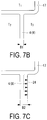
- FIG. 7A is a schematic view for explaining an effect of temperature differential on a vertical cross-sectional surface along a rib in the vertical direction provided on the side surface of the above-described motor housing.
- FIG. 7B is a schematic view for explaining the effect of temperature differential on a vertical cross-sectional surface along a rib in the vertical direction provided on the side surface of the above-described motor housing.
- FIG. 7C is a schematic view for explaining the effect of temperature differential on a vertical cross-sectional surface along a rib in the vertical direction provided on the side surface of the above-described motor housing.
- FIG. 8 is a right side view of FIG. 2 illustrating a motor housing according to another embodiment (1) of the present invention.
- FIG. 9 is a left side view of FIG. 2 illustrating a motor housing according to another embodiment (2) of the present invention.
- FIG. 10 is a right side view of FIG. 2 illustrating a motor housing according to another embodiment (3) of the present invention.
- FIG. 11 is a right side view of FIG. 2 illustrating a motor housing according to another embodiment (4) of the present invention.
- FIGS. 1 to 7C A first embodiment of the present invention will be described below with reference to FIGS. 1 to 7C .
- a vehicle-mounted electric compressor 1 includes a housing 2 in a tubular shape that is the outline of the vehicle-mounted electric compressor 1 .
- the housing 2 includes a compressor housing 3 including a compressor and a motor housing 4 including a motor 10 .
- the compressor housing 3 and the motor housing 4 are made of aluminum die-cast and integrally coupled to each other by a flange joint with a plurality of bolts 5 .
- the compressor housing 3 includes various types of compressors such as a scroll compressor, in the inside thereof.
- the compressor housing 3 is configured to compress a low-pressure refrigerant gas taken from a refrigerant circuit via the motor housing 4 to a high pressure by using the compressor.
- the compressor housing 3 is configured to then discharge the refrigerant gas with high pressure from the refrigerant discharge port 6 provided on the outer peripheral front end portion of the compressor housing 3 to the refrigerant circuit.
- the motor housing 4 includes a motor housing main body 8 in a tubular shape, one end of which is open to be coupled to the compressor housing 3 via a mating surface 7 , and the other end of which is closed.
- a cylindrical space 9 including the motor 10 in the inside thereof is thus defined in the motor housing 4 .
- the motor 10 includes a stator 11 and a rotor 12 .
- the stator 11 is fixed to and installed in the cylindrical space 9 by press fitting and the like.
- the rotor 12 is fitted to the center portion of the stator 11 with a motor gap interposed therebetween.
- the motor 10 is driven to rotate by three-phase AC power at a required frequency applied from a later-described inverter circuit 13 via a vacuum-tight feedthrough 14 .
- a plurality of refrigerant passages 15 are formed extending in the direction of a motor axis in a plurality of locations around the cylindrical space 9 including the stator 11 .
- the refrigerant passages 15 are configured to guide a low-pressure refrigerant gas introduced from a refrigerant intake port 16 provided on a side portion (side surface) on the rear end side of the motor housing main body 8 to the motor housing main body 8 , to the compressor housing 3 through the refrigerant passages 15 .
- an inverter accommodating portion 17 and compressor attachment feet 19 for installing the compressor to a vehicle are disposed around the outer periphery of the motor housing main body 8 .
- the inverter accommodating portion 17 formed in a rectangular shape in plan view is provided in an outer peripheral upper portion by integral molding.
- the inverter circuit 13 (specific circuit drawing is omitted) is accommodated and installed in the inverter accommodating portion 17 with a cover 18 capable of sealing the inverter accommodating portion 17 .
- the compressor attachment feet 19 for installing the compressor to a vehicle are disposed in three areas (three or four areas, for example) in upper and lower areas on the front end portion and a lower area on the rear end portion.
- the compressor attachment feet 19 are capable of fixing and installing the compressor to a vehicle in appropriate positions via a mounting bracket and the like.
- the inverter accommodating portion 17 is configured to accommodate and install the inverter circuit 13 (specific circuit drawing is omitted) in the inside thereof and to be sealed by the cover 18 .
- the inverter circuit 13 is a publicly known circuit including a power circuit board, a print circuit board, a filter circuit and the like. On the power circuit board, a switching circuit including a power transistor such as an IGBT is implemented. On the print circuit board, a control circuit such as a microcomputer that controls the power circuit board is implemented. The filter circuit is used for removing noise.
- the inverter circuit 13 is configured to convert a high-voltage DC power supplied from a power supply unit via a power supply cable and a terminal block 20 provided on the cover 18 to a three-phase AC power at required frequency. The inverter circuit 13 is configured to then apply the power to the motor 10 .
- control signals from a host control device can be input via a control and communication cable 21 .
- the inverter circuit 13 has heat-releasing electrical components such as a power transistor, and a condenser 22 and a coil 23 included in a high-voltage system filter circuit. Such heat-releasing electrical components need to be cooled suitably to maintain performance thereof for a long time.
- the bottom surface of the inverter accommodating portion 17 corresponds to a wall of the motor housing main body 8 . Inside the wall, the refrigerant passages 15 are formed. The heat-releasing electrical components included in the inverter circuit 13 are therefore cooled by the low-pressure refrigerant flowing through the inside of the motor housing main body 8 by using the motor housing main body 8 as a heat sink.
- the size of the inverter accommodating portion 17 formed in a rectangular shape in plan view is defined greater than the rear end surface and both side surfaces of the motor housing main body 8 , thus slightly protruding backward and laterally therefrom.
- This configuration cannot sufficiently transfer the heat released from the electrical components accommodated and installed along both side portions and along the rear end portion in the inverter accommodating portion 17 to the parts where the refrigerant passages 15 are provided via the wall portion (heat transfer portion) of the inverter accommodating portion 17 and the motor housing main body 8 , whereby cooling may be insufficient.
- the inverter accommodating portion 17 and the compressor attachment feet 19 are provided on the upper portion (upper surface) and the lower portion (lower surface) of the outer periphery of the motor housing main body 8 .
- This configuration ensures that sufficient rigidity is provided.
- no component to ensure such rigidity is provided on both side portions (both side surfaces) of the motor housing main body 8 .
- the rigidity thereof needs to be ensured by maintaining a certain thickness of a housing wall of the motor housing main body 8 .
- the wall thickness is reduced to reduce in weight thereof, the rigidity on both side portions (both side surfaces) is insufficient and thus the housing in a tubular shape is deformed and crushed in the vertical direction. This may unfortunately generate vibration and noise.
- one or more lines of ribs 24 are provided on the outer peripheral side portion (side surface) of the motor housing main body 8 , protruding outward and extending in the vertical direction.
- the ribs 24 are provided, as illustrated in FIGS. 1 and 5 , on the positions corresponding to the installation positions of the condenser 22 and the coil 23 included in the filter circuit of the inverter circuit 13 accommodated and installed along one side of the inverter accommodating portion 17 .
- the ribs 24 are provided in two lines parallel to each other, on each of which at least one line of rib is provided. But the present invention is not limited to the above-described example. For another example, only one line of the rib 24 may be provided with the width thereof increased. For still another example, three or more lines of the ribs 24 may be provided, as a matter of course.
- Each of the ribs 24 is formed integrally with the side surface of the motor housing main body 8 .
- the rib 24 is provided so as to protrude outward by a certain height thereof, extend in the vertical direction from the lower portion to the upper portion, and be connected to the bottom surface of the part protruding in the lateral direction of the inverter accommodating portion 17 .
- the present embodiment has the following operational effects.
- the above-described vehicle-mounted electric compressor 1 is mounted on a vehicle as a refrigerant compressor of a vehicular air conditioning device, and incorporated in the refrigerant circuit.
- the refrigerant gas filled in the refrigerant circuit is taken from the refrigerant intake port 16 into the motor housing main body 8 as a low-pressure refrigerant gas.
- the refrigerant gas subsequently flows through the refrigerant passages 15 around the motor 10 , and is then guided toward the compressor housing 3 .
- the low-pressure refrigerant gas is compressed by the compressor included in the compressor housing 3 , and then discharged from the refrigerant discharge port 6 toward the refrigerant circuit as a high-pressure refrigerant gas.
- the low-pressure refrigerant gas flowing through the refrigerant passages 15 inside the motor housing main body 8 cools the motor 10 .
- the low-pressure refrigerant gas also cools heat-releasing components such as the power transistor and the condenser 22 and the coil 23 in the high-voltage system among components of the inverter circuit 13 accommodated and installed in the inverter accommodating portion 17 , by using the motor housing main body 8 as a heat sink. This configuration prevents performance degradation caused by the heat released from the components, thereby ensuring the stable performance for a long time.
- the electric compressor motor housing 4 includes the motor housing main body 8 , the interior of which is the cylindrical space 9 for including the motor 10 , and in which the refrigerant passages 15 are formed around the cylindrical space 9 , in the direction of the motor axis.
- the electric compressor motor housing 4 further includes the inverter accommodating portion 17 provided in the upper portion of the outer periphery of the motor housing main body 8 .
- the electric compressor motor housing 4 further includes the compressor attachment feet 19 provided in the locations in the upper and lower portions of the outer periphery of the motor housing main body 8 .
- the electric compressor motor housing 4 further includes the refrigerant intake port 16 provided on the side surface on the rear end portion of the motor housing main body 8 .
- the electric compressor motor housing 4 includes one or more lines of ribs 24 provided on the outer peripheral side surface of the motor housing main body 8 , protruding outward and extending in the vertical direction.
- the upper portion and the lower portion of the outer periphery of the motor housing main body 8 is ensured to have sufficient rigidity because the inverter accommodating portion 17 and the compressor attachment feet 19 are provided thereon.
- the outer peripheral side surface of the motor housing main body 8 is liable to have insufficient rigidity.
- Providing one or more lines of the ribs 24 thereon protruding outward and extending in the vertical direction can thus increase the rigidity of the motor housing main body 8 without increasing the wall thickness of the entire housing.
- the ribs 24 increase the cross-sectional area of the wall portion coupling the side surface of the motor housing main body 8 to the inverter accommodating portion 17 provided in the upper portion of the outer periphery of the motor housing main body 8 . This configuration can increase the area of the radiating surface for heat transfer from the inverter accommodating portion 17 to the refrigerant flowing through the refrigerant passages 15 inside the motor housing main body 8 .
- This configuration can therefore increase the rigidity of the motor housing main body 8 and suppress deformation thereof, thereby reducing vibration and noise.
- this configuration can increase cooling performance of components of the inverter circuit 13 accommodated and installed in the inverter accommodating portion 17 . This can suppress performance degradation caused by the heat released from the components, and increase the reliability.
- B is a thickness of the housing wall portion
- E is an amount of heat
- A is an area of the heat transfer portion
- C is a coefficient of thermal conductivity
- Providing the ribs 24 as described above increases the thickness B of the wall portion, as illustrated in FIGS. 7B and 7C , from B 1 to B 2 (B 2 >B 1 ). As a result,
- the inverter circuit 13 When cooling the inverter circuit 13 , therefore, the effect of the temperature outside the compressor (outdoor temperature, for example) can be hardly received.
- the components of the inverter circuit 13 can be thus suitably cooled by utilizing the low-pressure refrigerant gas, thereby maintaining and ensuring the performance thereof.
- the ribs 24 are provided on the positions corresponding to the installation positions of the condenser 22 and the coil 23 included in the inverter circuit 13 accommodated and installed along one side of the inverter accommodating portion 17 . At least one line of the rib 24 is provided for each of the installation positions of the condenser 22 and the coil 23 .
- the condenser 22 and the coil 23 included in the filter circuit of the inverter circuit 13 are accommodated and installed along one side of the inverter accommodating portion 17 , the heat from the condenser 22 and the coil 23 can be released to the refrigerant flowing through the refrigerant passages 15 inside the motor housing main body 8 via the heat transfer portion (wall portion), the cross-sectional area thereof is increased by the ribs 24 provided on the positions corresponding to the installation positions of the condenser 22 and the coil 23 .
- this configuration achieves the following effect in addition to increasing the rigidity of the motor housing 4 to reduce vibration and noise. That is, the configuration can also ensure cooling performance for the condenser 22 and the coil 23 included in the filter circuit of the inverter circuit 13 , thereby suppressing performance degradation caused by the heat released from the components. Furthermore, the configuration can increase the flexibility of layout of components included in the filter circuit.
- FIGS. 8 to 11 Next, other embodiments of the present invention will be described with reference to FIGS. 8 to 11 .
- One or more lines of the ribs 24 may be provided on the outer peripheral side portion (side surface) of the motor housing main body 8 in the following manner.
- At least one line of the ribs 24 is provided in for each of the positions corresponding to the installation positions of the condenser 22 and the coil 23 included in the inverter circuit 13 , in the same manner as the above-described first embodiment.
- one line of a rib 24 A is further provided in the vertical direction along the vicinity of the mating surface 7 of the opening portion capable of coupling to the compressor housing 3 of the motor housing main body 8 .
- this configuration achieves the following effect in addition to increasing the rigidity of the motor housing 4 to reduce vibration and noise, and increasing cooling performance of components of the inverter circuit 13 , thereby suppressing performance degradation caused by the heat released from the components. That is, the configuration can further increase corrosion resistance of a seal member and the like provided on the mating surface 7 between the motor housing 4 and the compressor housing 3 .
- one or more ribs 24 with a predetermined space therebetween are provided on the side surface opposed to the side surface on which the refrigerant intake port 16 on the motor housing main body 8 is provided.
- the height of the lateral protrusion of the ribs 24 is defined same as the height of a side surface 17 A of the inverter accommodating portion 17 , as illustrated in FIG. 9 . That is, a flat surface 25 flush with the side surface 17 A of the inverter accommodating portion 17 is formed.
- this configuration When handling the electric compressor 1 , this configuration allows the electric compressor 1 to be placed in a stable manner with the flat surface 25 formed on the side surface of the motor housing main body 8 facing down. Therefore, this configuration achieves the following effect in addition to increasing the rigidity of the motor housing 4 to reduce vibration and noise, and increasing cooling performance of components of the inverter circuit 13 , thereby suppressing performance degradation caused by the heat released from the components. That is, the configuration can also facilitate handling when incorporating the electric compressor 1 to a vehicle, for example.
- one or more ribs 24 are provided on the side surface same as the side surface on which the refrigerant intake port 16 on the motor housing main body 8 is provided.
- the height of lateral protrusion of the ribs 24 is defined higher than the positions of a seat surface 16 A of the refrigerant intake port 16 and a seat surface 19 A of the compressor attachment feet 19 , as illustrated in FIG. 10 .
- This configuration can prevent the seat surface 16 A and the seat surface 19 A from being damaged because the height of protrusion of the ribs 24 is defined higher than the seat surface 16 A and the seat surface 19 A.
- This effect is achieved when placing the motor housing main body 8 with the side surface facing down on which the seat surface 16 A of the refrigerant intake port 16 and the seat surface 19 A of the compressor attachment feet 19 are provided.
- the effect is also achieved when other articles come into contact with the side surface on which the seat surface 16 A and the seat surface 19 A are provided. Therefore, this configuration achieves the following effect in addition to increasing the rigidity of the motor housing 4 to reduce vibration and noise, and increasing cooling performance of components of the inverter circuit 13 , thereby suppressing performance degradation caused by the heat released from the components. That is, the configuration can also eliminate refrigerant leakage or faulty installation of the electric compressor 1 caused by damage to the seat surface 16 A or the seat surface 19 A, for example.
- one or more ribs 24 are provided on the side surface same as the side surface on which the refrigerant intake port 16 on the motor housing main body 8 is provided.
- the height of lateral protrusion of the ribs 24 is defined higher than the height of outward protrusion of the side surface 17 A of the inverter accommodating portion 17 .
- This configuration can protect the inverter circuit 13 accommodated in the inverter accommodating portion 17 if the electric compressor 1 is mounted in a vehicle with the side surface of the motor housing main body 8 , on which the ribs 24 are provided, facing forward. This effect is achieved if the vehicle is involved in a collision accident and the rib portions having high rigidity can receive an impact thereof, for example. Therefore, this configuration achieves the following effect in addition to increasing the rigidity of the motor housing 4 to reduce vibration and noise, and increasing cooling performance of components of the inverter circuit 13 , thereby suppressing performance degradation caused by the heat released from the components. That is, the configuration can also prevent a high-voltage short circuit caused by damage to the inverter accommodating portion 17 if the vehicle is involved in a collision accident, and suppress expansion of the accident.
- the motor housing 4 is configured as described above, and such that an opening portion at one end thereof is coupled to the compressor housing 3 including the compressor. That is, the inverter circuit 13 is integrally incorporated in the housing 2 including the motor 10 and the compressor.
- This configuration can therefore increase the rigidity of the motor housing 4 of the electric compressor 1 and suppress deformation thereof, thereby reducing vibration and noise.
- this configuration can increase cooling performance of components of the inverter circuit 13 accommodated in the inverter accommodating portion 17 . This suppresses performance degradation caused by the heat released from the components. The configuration can thus increase the reliability and achieve the vehicle-mounted electric compressor 1 with lower noise.
- the present invention is not limited to the invention according to the above-described embodiments and can be modified as required without departing from the spirit of the present invention.
- the compressor included in the compressor housing 3 may be any type of compressors. It is to be understood that the configuration of the inverter circuit 13 accommodated and installed in the inverter accommodating portion 17 or power supply configuration of electric power and control signals to the inverter circuit 13 can be modified in a variety of other forms.
Abstract
Description
D=(B×E)/(A×C)·T 3 >T 1 >T 2
- 1 Vehicle-mounted electric compressor
- 2 Housing
- 3 Compressor housing
- 4 Motor housing
- 7 Mating surface
- 8 Motor housing main body
- 9 Cylindrical space
- 10 Motor
- 13 Inverter circuit
- 15 Refrigerant passage
- 16 Refrigerant intake port
- 16A Refrigerant intake port seat surface
- 17 Inverter accommodating portion
- 17A Inverter accommodating portion side surface
- 19 Compressor attachment feet
- 19A Compressor attachment feet seat surface
- 22 Condenser
- 23 Coil
- 24, 24A Rib
- 25 Flat surface
Claims (20)
Applications Claiming Priority (4)
| Application Number | Priority Date | Filing Date | Title |
|---|---|---|---|
| JP2015103778A JP6700674B2 (en) | 2015-05-21 | 2015-05-21 | Motor housing for electric compressor and vehicle-mounted electric compressor using the same |
| JPJP2015-103778 | 2015-05-21 | ||
| JP2015-103778 | 2015-05-21 | ||
| PCT/JP2016/057515 WO2016185770A1 (en) | 2015-05-21 | 2016-03-10 | Electric compressor motor housing, and vehicle-mounted electric compressor employing same |
Publications (2)
| Publication Number | Publication Date |
|---|---|
| US20180076681A1 US20180076681A1 (en) | 2018-03-15 |
| US10923982B2 true US10923982B2 (en) | 2021-02-16 |
Family
ID=57319840
Family Applications (1)
| Application Number | Title | Priority Date | Filing Date |
|---|---|---|---|
| US15/558,129 Active 2036-08-08 US10923982B2 (en) | 2015-05-21 | 2016-03-10 | Electric compressor motor housing, and vehicle-mounted electric compressor employing same |
Country Status (5)
| Country | Link |
|---|---|
| US (1) | US10923982B2 (en) |
| JP (1) | JP6700674B2 (en) |
| CN (1) | CN107534354B (en) |
| DE (1) | DE112016002300T5 (en) |
| WO (1) | WO2016185770A1 (en) |
Cited By (1)
| Publication number | Priority date | Publication date | Assignee | Title |
|---|---|---|---|---|
| US20200381981A1 (en) * | 2018-02-23 | 2020-12-03 | Sanden Automotive Components Corporation | Electric Compressor |
Families Citing this family (9)
| Publication number | Priority date | Publication date | Assignee | Title |
|---|---|---|---|---|
| AU2018377857B2 (en) * | 2017-12-01 | 2021-04-08 | Rencool Pty Ltd | DC voltage air conditioning compressor drive unit |
| GB2576732B (en) | 2018-08-29 | 2020-12-30 | Ford Global Tech Llc | A motor vehicle assembly having improved collision integrity |
| US11486484B2 (en) * | 2018-10-22 | 2022-11-01 | Nidec Corporation | Motor assembly |
| JP7346823B2 (en) * | 2018-10-22 | 2023-09-20 | ニデック株式会社 | motor unit |
| JP2021016257A (en) * | 2019-07-12 | 2021-02-12 | 日本電産株式会社 | Motor unit |
| US20230344303A1 (en) * | 2020-02-14 | 2023-10-26 | Nidec Corporation | Motor and motor unit |
| DE102020206124A1 (en) | 2020-05-14 | 2021-11-18 | Volkswagen Aktiengesellschaft | Contact device and electric motor |
| JP2024512461A (en) * | 2021-03-15 | 2024-03-19 | アメリカン アクスル アンド マニュファクチャリング,インコーポレイテッド | Electric drive module configured as a beam axle |
| JP2024046195A (en) * | 2022-09-22 | 2024-04-03 | サンデン株式会社 | Electric Compressor |
Citations (25)
| Publication number | Priority date | Publication date | Assignee | Title |
|---|---|---|---|---|
| WO1993023266A1 (en) | 1992-05-12 | 1993-11-25 | Seiko Epson Corporation | Electric car |
| JPH0670507A (en) | 1992-08-07 | 1994-03-11 | Nippondenso Co Ltd | Liquid-cooled electric rotary machine |
| DE20007099U1 (en) | 1999-05-06 | 2000-09-28 | Wernert & Co Ohg H | Centrifugal pump |
| US20030161742A1 (en) | 2002-02-22 | 2003-08-28 | A. O. Smith Corporation | Combination shield and conduit box cover |
| US20030200761A1 (en) | 2002-04-26 | 2003-10-30 | Denso Corporation | Inverter-integrated motor for an automotive vehicle |
| JP2004162618A (en) | 2002-11-13 | 2004-06-10 | Denso Corp | Horizontal inverter type electric compressor for vehicle |
| JP2004197688A (en) | 2002-12-20 | 2004-07-15 | Calsonic Compressor Seizo Kk | Electric compressor |
| JP2006197785A (en) | 2004-12-14 | 2006-07-27 | Nissan Motor Co Ltd | Cooling device of motor |
| JP2009092000A (en) | 2007-10-10 | 2009-04-30 | Mitsubishi Heavy Ind Ltd | Compressor for on-vehicle air-conditioner |
| JP2009103100A (en) | 2007-10-25 | 2009-05-14 | Denso Corp | Vehicle electric compressor |
| US20090289513A1 (en) | 2008-05-21 | 2009-11-26 | Emerson Electric Co. | Cooling System for a Motor and Associated Electronics |
| WO2011037136A1 (en) | 2009-09-24 | 2011-03-31 | 三菱重工業株式会社 | Inverter integrated motor-driven compressor |
| JP2012117445A (en) | 2010-11-30 | 2012-06-21 | Mitsubishi Heavy Ind Ltd | Inverter housing part, and electric compressor integrated with inverter including the same |
| US20130119794A1 (en) | 2011-11-10 | 2013-05-16 | Kabushiki Kaisha Yaskawa Denki | Rotating electrical machine |
| WO2013171957A1 (en) | 2012-05-15 | 2013-11-21 | パナソニック株式会社 | Electric compressor |
| US20140144412A1 (en) * | 2011-07-15 | 2014-05-29 | Mitsubishi Heavy Industries, Ltd. | Electric supercharging device and multi-stage supercharging system |
| JP2014165944A (en) | 2013-02-21 | 2014-09-08 | Mitsubishi Heavy Industries Automotive Thermal Systems Co Ltd | Inverter-integrated motor-driven compressor |
| US20140354088A1 (en) | 2011-12-23 | 2014-12-04 | Grundfos Holding A/S | Electric motor |
| US20150001973A1 (en) | 2012-02-08 | 2015-01-01 | Grundfos Holding A/S | Electric motor |
| US20150211525A1 (en) | 2011-12-23 | 2015-07-30 | Grundfos Holding A/S | Wet-running centrifugal pump |
| US20150333593A1 (en) | 2011-12-23 | 2015-11-19 | Grundfos Holding A/S | Electric drive motor |
| US20150340933A1 (en) * | 2013-02-20 | 2015-11-26 | Mitsubishi Heavy Industries Automotive Thermal Systems Co., Ltd. | Inverter-integrated electric compressor |
| US20170127566A1 (en) * | 2014-08-29 | 2017-05-04 | Denso Corporation | Cooling structure for electronic components and electric compressor |
| EP3182565A1 (en) | 2015-12-15 | 2017-06-21 | Wilo Se | Electronics housing with cooling fins |
| US10298089B2 (en) * | 2014-06-27 | 2019-05-21 | Sanden Holdings Corporation | Electric compressor |
Family Cites Families (6)
| Publication number | Priority date | Publication date | Assignee | Title |
|---|---|---|---|---|
| JP5393324B2 (en) * | 2009-07-30 | 2014-01-22 | 三菱重工業株式会社 | Inverter-integrated electric compressor |
| KR20120016833A (en) * | 2010-08-17 | 2012-02-27 | 학교법인 두원학원 | Electric compressor of vehicle |
| JP5722644B2 (en) * | 2011-01-27 | 2015-05-27 | 株式会社日立産機システム | Rotating electric machine |
| CN202210735U (en) * | 2011-09-29 | 2012-05-02 | 金进精密泵业制品(深圳)有限公司 | Integrated motor |
| CN202475120U (en) * | 2012-03-01 | 2012-10-03 | 光陆机电有限公司 | Safe and reliable motor shell |
| CN104125154B (en) * | 2014-08-12 | 2017-09-26 | 华为技术有限公司 | Method for discovering network topology and equipment |
-
2015
- 2015-05-21 JP JP2015103778A patent/JP6700674B2/en active Active
-
2016
- 2016-03-10 US US15/558,129 patent/US10923982B2/en active Active
- 2016-03-10 DE DE112016002300.6T patent/DE112016002300T5/en not_active Withdrawn
- 2016-03-10 WO PCT/JP2016/057515 patent/WO2016185770A1/en active Application Filing
- 2016-03-10 CN CN201680015602.1A patent/CN107534354B/en active Active
Patent Citations (35)
| Publication number | Priority date | Publication date | Assignee | Title |
|---|---|---|---|---|
| US5900686A (en) | 1902-09-09 | 1999-05-04 | Seiko Epson Corporation | Electric motor vehicle |
| WO1993023266A1 (en) | 1992-05-12 | 1993-11-25 | Seiko Epson Corporation | Electric car |
| US6037726A (en) | 1992-05-12 | 2000-03-14 | Seiko Epson Corporation | Electric motor vehicle |
| US6054818A (en) | 1992-05-12 | 2000-04-25 | Seiko Epson Corporation | Electric motor vehicle |
| JPH0670507A (en) | 1992-08-07 | 1994-03-11 | Nippondenso Co Ltd | Liquid-cooled electric rotary machine |
| DE20007099U1 (en) | 1999-05-06 | 2000-09-28 | Wernert & Co Ohg H | Centrifugal pump |
| US20030161742A1 (en) | 2002-02-22 | 2003-08-28 | A. O. Smith Corporation | Combination shield and conduit box cover |
| US20030200761A1 (en) | 2002-04-26 | 2003-10-30 | Denso Corporation | Inverter-integrated motor for an automotive vehicle |
| JP2004162618A (en) | 2002-11-13 | 2004-06-10 | Denso Corp | Horizontal inverter type electric compressor for vehicle |
| JP2004197688A (en) | 2002-12-20 | 2004-07-15 | Calsonic Compressor Seizo Kk | Electric compressor |
| JP2006197785A (en) | 2004-12-14 | 2006-07-27 | Nissan Motor Co Ltd | Cooling device of motor |
| JP2009092000A (en) | 2007-10-10 | 2009-04-30 | Mitsubishi Heavy Ind Ltd | Compressor for on-vehicle air-conditioner |
| US20100172772A1 (en) | 2007-10-10 | 2010-07-08 | Mitsubishi Heavy Industries, Ltd. | Vehicle-air-conditioner compressor |
| JP2009103100A (en) | 2007-10-25 | 2009-05-14 | Denso Corp | Vehicle electric compressor |
| US20110266898A1 (en) | 2008-05-21 | 2011-11-03 | Nidec Motor Corporation | Cooling System for a Motor and Associated Electronics |
| US20090289513A1 (en) | 2008-05-21 | 2009-11-26 | Emerson Electric Co. | Cooling System for a Motor and Associated Electronics |
| WO2011037136A1 (en) | 2009-09-24 | 2011-03-31 | 三菱重工業株式会社 | Inverter integrated motor-driven compressor |
| US20120045353A1 (en) | 2009-09-24 | 2012-02-23 | Mitsubishi Heavy Industries, Ltd. | Inverter-integrated electric compressor |
| JP2012117445A (en) | 2010-11-30 | 2012-06-21 | Mitsubishi Heavy Ind Ltd | Inverter housing part, and electric compressor integrated with inverter including the same |
| US20140144412A1 (en) * | 2011-07-15 | 2014-05-29 | Mitsubishi Heavy Industries, Ltd. | Electric supercharging device and multi-stage supercharging system |
| US20130119794A1 (en) | 2011-11-10 | 2013-05-16 | Kabushiki Kaisha Yaskawa Denki | Rotating electrical machine |
| JP2013106365A (en) | 2011-11-10 | 2013-05-30 | Yaskawa Electric Corp | Rotary electric machine |
| US20150333593A1 (en) | 2011-12-23 | 2015-11-19 | Grundfos Holding A/S | Electric drive motor |
| US20150211525A1 (en) | 2011-12-23 | 2015-07-30 | Grundfos Holding A/S | Wet-running centrifugal pump |
| US20140354088A1 (en) | 2011-12-23 | 2014-12-04 | Grundfos Holding A/S | Electric motor |
| US20150001973A1 (en) | 2012-02-08 | 2015-01-01 | Grundfos Holding A/S | Electric motor |
| US20150044075A1 (en) | 2012-05-15 | 2015-02-12 | Panasonic Corporation | Electric compressor |
| WO2013171957A1 (en) | 2012-05-15 | 2013-11-21 | パナソニック株式会社 | Electric compressor |
| US20150340933A1 (en) * | 2013-02-20 | 2015-11-26 | Mitsubishi Heavy Industries Automotive Thermal Systems Co., Ltd. | Inverter-integrated electric compressor |
| JP2014165944A (en) | 2013-02-21 | 2014-09-08 | Mitsubishi Heavy Industries Automotive Thermal Systems Co Ltd | Inverter-integrated motor-driven compressor |
| DE112013006708T5 (en) | 2013-02-21 | 2015-10-29 | Mitsubishi Heavy Industries Automotive Thermal Systems Co., Ltd. | Electric compressor with integrated inverter |
| US20150349613A1 (en) | 2013-02-21 | 2015-12-03 | Mitsubishi Heavy Industries Automotive Thermal Systems Co., Ltd. | Inverter-integrated electric compressor |
| US10298089B2 (en) * | 2014-06-27 | 2019-05-21 | Sanden Holdings Corporation | Electric compressor |
| US20170127566A1 (en) * | 2014-08-29 | 2017-05-04 | Denso Corporation | Cooling structure for electronic components and electric compressor |
| EP3182565A1 (en) | 2015-12-15 | 2017-06-21 | Wilo Se | Electronics housing with cooling fins |
Non-Patent Citations (3)
| Title |
|---|
| Office Action dated Mar. 3, 2020 in corresponding German Application 112016002300.6 with an English Translation. |
| Office Action dated Nov. 26, 2019 in related Japanese Patent Application No. 2015-103778 with an English Translation. |
| Written Opinion of the International Searching Authority and International Search Report (forms PCT/ISA/237 and PCT/ISA/210), dated Jun. 14, 2016, for International Application No. PCT/JP2016/057515, with English translations. |
Cited By (2)
| Publication number | Priority date | Publication date | Assignee | Title |
|---|---|---|---|---|
| US20200381981A1 (en) * | 2018-02-23 | 2020-12-03 | Sanden Automotive Components Corporation | Electric Compressor |
| US11936251B2 (en) * | 2018-02-23 | 2024-03-19 | Sanden Automotive Components Corporation | Electric compressor with inverter circuit section and filter circuit section |
Also Published As
| Publication number | Publication date |
|---|---|
| US20180076681A1 (en) | 2018-03-15 |
| CN107534354B (en) | 2020-05-15 |
| JP2016220424A (en) | 2016-12-22 |
| DE112016002300T5 (en) | 2018-03-08 |
| JP6700674B2 (en) | 2020-05-27 |
| WO2016185770A1 (en) | 2016-11-24 |
| CN107534354A (en) | 2018-01-02 |
Similar Documents
| Publication | Publication Date | Title |
|---|---|---|
| US10923982B2 (en) | Electric compressor motor housing, and vehicle-mounted electric compressor employing same | |
| US9494149B2 (en) | Inverter-integrated electric compressor | |
| US8408883B2 (en) | Vehicle-air-conditioner electric compressor | |
| US9157425B2 (en) | Inverter-integrated electric compressor | |
| EP2206922B1 (en) | Inverter-integrated electric compressor | |
| US9115707B2 (en) | Inverter module and integrated-inverter electric compressor using the same | |
| US8882479B2 (en) | Integrated-inverter electric compressor | |
| US8435019B2 (en) | Vehicle-air-conditioner electric compressor | |
| US8717765B2 (en) | Integrated-inverter electric compressor and inverter unit thereof | |
| US9293969B2 (en) | Inverter module and inverter integrated electric compressor | |
| US20100181876A1 (en) | Inverter-integrated electric compressor | |
| JP5393015B2 (en) | In-vehicle air conditioner compressor | |
| CN110429765B (en) | Motor housing for an electric compressor of an air conditioning system | |
| US8152487B2 (en) | Inverter-integrated electric compressor | |
| CN109121457A (en) | Electronic-circuit device and inverter-integrated type electric compressor including the electronic-circuit device | |
| US20100129238A1 (en) | Inverter-integrated electric compressor and coil component for inverter thereof | |
| CN104769283A (en) | Invertor-integrated electric compressor | |
| JP5595461B2 (en) | Inverter-integrated electric compressor | |
| US20100028173A1 (en) | Inverter-integrated electric compressor |
Legal Events
| Date | Code | Title | Description |
|---|---|---|---|
| FEPP | Fee payment procedure |
Free format text: ENTITY STATUS SET TO UNDISCOUNTED (ORIGINAL EVENT CODE: BIG.); ENTITY STATUS OF PATENT OWNER: LARGE ENTITY |
|
| AS | Assignment |
Owner name: MITSUBISHI HEAVY INDUSTRIES AUTOMOTIVE THERMAL SYSTEMS CO., LTD., JAPAN Free format text: ASSIGNMENT OF ASSIGNORS INTEREST;ASSIGNORS:IKETAKA, GOSHI;YAMAZAKI, HIROSHI;ISHIKAWA, MASAYUKI;AND OTHERS;REEL/FRAME:043592/0412 Effective date: 20170629 Owner name: MITSUBISHI HEAVY INDUSTRIES AUTOMOTIVE THERMAL SYS Free format text: ASSIGNMENT OF ASSIGNORS INTEREST;ASSIGNORS:IKETAKA, GOSHI;YAMAZAKI, HIROSHI;ISHIKAWA, MASAYUKI;AND OTHERS;REEL/FRAME:043592/0412 Effective date: 20170629 |
|
| STPP | Information on status: patent application and granting procedure in general |
Free format text: DOCKETED NEW CASE - READY FOR EXAMINATION |
|
| AS | Assignment |
Owner name: MITSUBISHI HEAVY INDUSTRIES THERMAL SYSTEMS, LTD., JAPAN Free format text: MERGER;ASSIGNOR:MITSUBISHI HEAVY INDUSTRIES AUTOMOTIVE THERMAL SYSTEMS CO., LTD.;REEL/FRAME:046318/0599 Effective date: 20180104 Owner name: MITSUBISHI HEAVY INDUSTRIES THERMAL SYSTEMS, LTD., Free format text: MERGER;ASSIGNOR:MITSUBISHI HEAVY INDUSTRIES AUTOMOTIVE THERMAL SYSTEMS CO., LTD.;REEL/FRAME:046318/0599 Effective date: 20180104 |
|
| STPP | Information on status: patent application and granting procedure in general |
Free format text: EX PARTE QUAYLE ACTION MAILED |
|
| STPP | Information on status: patent application and granting procedure in general |
Free format text: NOTICE OF ALLOWANCE MAILED -- APPLICATION RECEIVED IN OFFICE OF PUBLICATIONS |
|
| STPP | Information on status: patent application and granting procedure in general |
Free format text: PUBLICATIONS -- ISSUE FEE PAYMENT RECEIVED |
|
| STPP | Information on status: patent application and granting procedure in general |
Free format text: AWAITING TC RESP, ISSUE FEE PAYMENT VERIFIED |
|
| STPP | Information on status: patent application and granting procedure in general |
Free format text: WITHDRAW FROM ISSUE AWAITING ACTION |
|
| STPP | Information on status: patent application and granting procedure in general |
Free format text: NON FINAL ACTION MAILED |
|
| STPP | Information on status: patent application and granting procedure in general |
Free format text: NOTICE OF ALLOWANCE MAILED -- APPLICATION RECEIVED IN OFFICE OF PUBLICATIONS |
|
| STCF | Information on status: patent grant |
Free format text: PATENTED CASE |