US1091663A - Gas-burner. - Google Patents
Gas-burner. Download PDFInfo
- Publication number
- US1091663A US1091663A US77817113A US1913778171A US1091663A US 1091663 A US1091663 A US 1091663A US 77817113 A US77817113 A US 77817113A US 1913778171 A US1913778171 A US 1913778171A US 1091663 A US1091663 A US 1091663A
- Authority
- US
- United States
- Prior art keywords
- burner
- gas
- spindle
- secured
- cam
- Prior art date
- Legal status (The legal status is an assumption and is not a legal conclusion. Google has not performed a legal analysis and makes no representation as to the accuracy of the status listed.)
- Expired - Lifetime
Links
- 238000010276 construction Methods 0.000 description 2
- 230000003247 decreasing effect Effects 0.000 description 1
- 230000005484 gravity Effects 0.000 description 1
- 238000010438 heat treatment Methods 0.000 description 1
- 210000003141 lower extremity Anatomy 0.000 description 1
- 210000003813 thumb Anatomy 0.000 description 1
Images
Classifications
-
- B—PERFORMING OPERATIONS; TRANSPORTING
- B05—SPRAYING OR ATOMISING IN GENERAL; APPLYING FLUENT MATERIALS TO SURFACES, IN GENERAL
- B05B—SPRAYING APPARATUS; ATOMISING APPARATUS; NOZZLES
- B05B1/00—Nozzles, spray heads or other outlets, with or without auxiliary devices such as valves, heating means
- B05B1/12—Nozzles, spray heads or other outlets, with or without auxiliary devices such as valves, heating means capable of producing different kinds of discharge, e.g. either jet or spray
Definitions
- the objects of the invention are to pro- I ride a, simple, eflicient and inexpensive means of adjusting the nature and size of the flame of a gas jet when used in conjunction with a conical flame spreader.
- the invention consists essentially in the novel construction and arrangement of parts hereinafter described.
- Figurel is a sectional elevation of the device
- Fig. 2 is a general perspective view of the device.
- 1 is a conical flamespreader which is secured to the adjusting spindle 2, and adapted to close the orifice 3 in burner 4, when said flame spreader is in its closed position. (shown dotted in the drawing).
- lug 5 is a lug extending vertically downward from'burner 4:, and is provided with 'anorifice 6 adapted to receive spindle 2 and allow no perceptible lateral movement or leakage a free vertical movement for it, yet allow of "as between said spindle and said 111 In t e lower extremity of lug 5, is a slot I, adapted to receive the cam 8 which is pivotally secured therein by the pin 9.
- the cam S is. formed witha heel 10, and an orifice 11 therein adapted to provide means for pivotally securing the adj ustment-rod 12. If found desirable the cam ,8 may be formed with a stop projection 13.
- 1 1 is a tube connecting the mixing chamber 15 to the burner 4.
- the mixing chamber 15 is of the usual type, having a nozzle '16 supported from the body 15 by a plurality of arms 17, said nozzle being adapted to receive the gas-supply pipe 18.
- 19 is an arr-regulating battle provided with a clamping arm 20, which may be secured by a knurled nut 21 at any distance found suitable from the back 22 of the mixing chamber.
- the mixing chamber may be secured to the connecting tube 14:, by the screws 23, or any other convenient means may be utilized for this purpose.
- a guide pillar for adjustmentrod 12 is a guide pillar for adjustmentrod 12; and may be secured atone end to the mixing-chamber; the other end is provided with an orifice 25 and a thumb screw 26 respectively adapted to receive and secure the adjustment rod 12.
- This burner is especially adapted for use in furnaces and in heating stoves, boilers and the like, but I do not wish to limit its application entirely to use in these apparatuses.
- a conical flame spreader In a gas burner, a conical flame spreader, a spindle secured to the flame spreader, a lug provided with an orifice adapted to slidably secure the spindle, and having a slit at one end of said lug, a cam pivot-ally secured in said slit, and adapted to operate said spindle, a rod operating said cam, and means for securing said rod at various posi tions.
Landscapes
- Gas Burners (AREA)
Description
G. B. KILLAM. GAS BURNER.
APPLIOATION FILED JULY 9, 1913.
1,0915663J Patented Mar. 31, 19M
WITNESSES Iiv VEN 707? a" BY q.a.K/L,LAM
ATTYB iOL GASTON B. KILLAJ I, OF CALGARY, ALBERTA, CANADA.
GAS-BURNER.
Specification of Letters Patent.
Patented Mar. 31, 1914.
Application filed July 9, 1913. Serial No. 778,171.
To all whoa-L it may concern Be it known that I, GASTON B. Kmart, a citizen of the United States of America, residing at 517 Fifth avenue west, in the city of Calgary, Province of Alberta, Dominion of Canada, have invented certain new and useful Improvements in Gas-Burners, of which the following is a specification.
This invention relates to improvements in )urners, as more specifically set forth in inc following specification, and the accompanying drawings that form part of the same.
The objects of the invention are to pro- I ride a, simple, eflicient and inexpensive means of adjusting the nature and size of the flame of a gas jet when used in conjunction with a conical flame spreader.
The invention consists essentially in the novel construction and arrangement of parts hereinafter described.
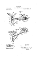
In the drawings: Figurel is a sectional elevation of the device, and Fig. 2 is a general perspective view of the device.
In the drawings like numerals of reference indicate corresponding parts in each figure.
Referring to the drawings, 1 is a conical flamespreader which is secured to the adjusting spindle 2, and adapted to close the orifice 3 in burner 4, when said flame spreader is in its closed position. (shown dotted in the drawing).
5 is a lug extending vertically downward from'burner 4:, and is provided with 'anorifice 6 adapted to receive spindle 2 and allow no perceptible lateral movement or leakage a free vertical movement for it, yet allow of "as between said spindle and said 111 In t e lower extremity of lug 5, is a slot I, adapted to receive the cam 8 which is pivotally secured therein by the pin 9. The cam S is. formed witha heel 10, and an orifice 11 therein adapted to provide means for pivotally securing the adj ustment-rod 12. If found desirable the cam ,8 may be formed with a stop projection 13.
1 1 is a tube connecting the mixing chamber 15 to the burner 4. o
The mixing chamber 15 is of the usual type, having a nozzle '16 supported from the body 15 by a plurality of arms 17, said nozzle being adapted to receive the gas-supply pipe 18.
19 is an arr-regulating battle provided with a clamping arm 20, which may be secured by a knurled nut 21 at any distance found suitable from the back 22 of the mixing chamber. The mixing chamber may be secured to the connecting tube 14:, by the screws 23, or any other convenient means may be utilized for this purpose.
24: is a guide pillar for adjustmentrod 12; and may be secured atone end to the mixing-chamber; the other end is provided with an orifice 25 and a thumb screw 26 respectively adapted to receive and secure the adjustment rod 12.
In the operation of this device, it will readily be followed that by moving the rod 12 backward and forward the size of the flame will be increased or decreased, on account of the cam 8 to which said rod is attached pressing up or allowing to fall by gravity, the spindle 2 with its spreader cone 1, thus opening orclosing the orifice 3 which is the exit of the gas to be burned; it will also be obvious that the arrangementand construction of the baflle 19 is admirably suited for the regulation of air admission to the mixing chamber and-that the combination of these features would produce a burner easy of adjustment and eflicient in operation.
This burner is especially adapted for use in furnaces and in heating stoves, boilers and the like, but I do not wish to limit its application entirely to use in these apparatuses.
\Vhat I claim as my invention is:
In a gas burner, a conical flame spreader, a spindle secured to the flame spreader, a lug provided with an orifice adapted to slidably secure the spindle, and having a slit at one end of said lug, a cam pivot-ally secured in said slit, and adapted to operate said spindle, a rod operating said cam, and means for securing said rod at various posi tions.
In witness whereof I have hereunto set my hand in the presence of two witnesses.
GASTON B. KILLAM.
WVitnesses:
D. R. CRICHTON, H. E. ANDERSON.
Priority Applications (1)
| Application Number | Priority Date | Filing Date | Title |
|---|---|---|---|
| US77817113A US1091663A (en) | 1913-07-09 | 1913-07-09 | Gas-burner. |
Applications Claiming Priority (1)
| Application Number | Priority Date | Filing Date | Title |
|---|---|---|---|
| US77817113A US1091663A (en) | 1913-07-09 | 1913-07-09 | Gas-burner. |
Publications (1)
| Publication Number | Publication Date |
|---|---|
| US1091663A true US1091663A (en) | 1914-03-31 |
Family
ID=3159879
Family Applications (1)
| Application Number | Title | Priority Date | Filing Date |
|---|---|---|---|
| US77817113A Expired - Lifetime US1091663A (en) | 1913-07-09 | 1913-07-09 | Gas-burner. |
Country Status (1)
| Country | Link |
|---|---|
| US (1) | US1091663A (en) |
Cited By (2)
| Publication number | Priority date | Publication date | Assignee | Title |
|---|---|---|---|---|
| US2572675A (en) * | 1947-04-07 | 1951-10-23 | Cleveland Res Corp | Gas burner with modulated flame orifice |
| US3179154A (en) * | 1962-10-30 | 1965-04-20 | Raymond W Sargent | Gas burner construction |
-
1913
- 1913-07-09 US US77817113A patent/US1091663A/en not_active Expired - Lifetime
Cited By (2)
| Publication number | Priority date | Publication date | Assignee | Title |
|---|---|---|---|---|
| US2572675A (en) * | 1947-04-07 | 1951-10-23 | Cleveland Res Corp | Gas burner with modulated flame orifice |
| US3179154A (en) * | 1962-10-30 | 1965-04-20 | Raymond W Sargent | Gas burner construction |
Similar Documents
| Publication | Publication Date | Title |
|---|---|---|
| US1091663A (en) | Gas-burner. | |
| US1272263A (en) | Atmospheric gas-burner. | |
| US1009678A (en) | Liquid-fuel burner. | |
| US599809A (en) | Incandescent gas-burner | |
| US123327A (en) | Improvement in gas-burners | |
| US920914A (en) | Gas-cock. | |
| US295315A (en) | Vapor-burner | |
| US788670A (en) | Gas-burner bracket. | |
| US709830A (en) | Gas-blowpipe. | |
| US615960A (en) | Blowpipe | |
| US968252A (en) | Fluid-hydrocarbon burner. | |
| US163007A (en) | William garland | |
| US347712A (en) | Vapor-burner | |
| US792096A (en) | Automatic gas-regulating apparatus. | |
| US787914A (en) | Gas-stove. | |
| US761924A (en) | Gas-burner. | |
| US397904A (en) | William f | |
| US732981A (en) | Gas-check for bunsen burners. | |
| US1153643A (en) | Automatically-adjustable mixer for gas-burner valves. | |
| US620692A (en) | Gas-bracket | |
| US733160A (en) | Gas-burner. | |
| US58606A (en) | Improvement in gas-burners | |
| US412765A (en) | Lindsay | |
| US746546A (en) | Regulator for gas-burners. | |
| US245711A (en) | Vapor-burner |