US10895833B2 - Sliding sheet and method for manufacturing the same - Google Patents
Sliding sheet and method for manufacturing the same Download PDFInfo
- Publication number
- US10895833B2 US10895833B2 US15/871,143 US201815871143A US10895833B2 US 10895833 B2 US10895833 B2 US 10895833B2 US 201815871143 A US201815871143 A US 201815871143A US 10895833 B2 US10895833 B2 US 10895833B2
- Authority
- US
- United States
- Prior art keywords
- edge
- sliding sheet
- warp yarns
- yarns
- fabric
- Prior art date
- Legal status (The legal status is an assumption and is not a legal conclusion. Google has not performed a legal analysis and makes no representation as to the accuracy of the status listed.)
- Active, expires
Links
- 238000000034 method Methods 0.000 title abstract description 37
- 238000004519 manufacturing process Methods 0.000 title abstract description 25
- 239000004744 fabric Substances 0.000 claims abstract description 221
- 238000010438 heat treatment Methods 0.000 claims description 28
- 238000009941 weaving Methods 0.000 abstract description 39
- 238000005452 bending Methods 0.000 abstract description 15
- 239000000314 lubricant Substances 0.000 description 23
- 238000005520 cutting process Methods 0.000 description 20
- 230000000694 effects Effects 0.000 description 4
- 230000007774 longterm Effects 0.000 description 4
- 239000000463 material Substances 0.000 description 3
- 239000002245 particle Substances 0.000 description 3
- 238000009826 distribution Methods 0.000 description 2
- OKTJSMMVPCPJKN-UHFFFAOYSA-N Carbon Chemical compound [C] OKTJSMMVPCPJKN-UHFFFAOYSA-N 0.000 description 1
- 239000004734 Polyphenylene sulfide Substances 0.000 description 1
- 238000004220 aggregation Methods 0.000 description 1
- 230000002776 aggregation Effects 0.000 description 1
- 229910052799 carbon Inorganic materials 0.000 description 1
- 230000005684 electric field Effects 0.000 description 1
- 238000005516 engineering process Methods 0.000 description 1
- 239000007788 liquid Substances 0.000 description 1
- 108091008695 photoreceptors Proteins 0.000 description 1
- 229920000069 polyphenylene sulfide Polymers 0.000 description 1
- -1 polytetrafluoroethylene Polymers 0.000 description 1
- 229920001343 polytetrafluoroethylene Polymers 0.000 description 1
- 239000004810 polytetrafluoroethylene Substances 0.000 description 1
- 238000003825 pressing Methods 0.000 description 1
Images


Classifications
-
- G—PHYSICS
- G03—PHOTOGRAPHY; CINEMATOGRAPHY; ANALOGOUS TECHNIQUES USING WAVES OTHER THAN OPTICAL WAVES; ELECTROGRAPHY; HOLOGRAPHY
- G03G—ELECTROGRAPHY; ELECTROPHOTOGRAPHY; MAGNETOGRAPHY
- G03G15/00—Apparatus for electrographic processes using a charge pattern
- G03G15/20—Apparatus for electrographic processes using a charge pattern for fixing, e.g. by using heat
- G03G15/2003—Apparatus for electrographic processes using a charge pattern for fixing, e.g. by using heat using heat
- G03G15/2014—Apparatus for electrographic processes using a charge pattern for fixing, e.g. by using heat using heat using contact heat
- G03G15/2053—Structural details of heat elements, e.g. structure of roller or belt, eddy current, induction heating
-
- D—TEXTILES; PAPER
- D03—WEAVING
- D03D—WOVEN FABRICS; METHODS OF WEAVING; LOOMS
- D03D1/00—Woven fabrics designed to make specified articles
-
- D—TEXTILES; PAPER
- D03—WEAVING
- D03D—WOVEN FABRICS; METHODS OF WEAVING; LOOMS
- D03D11/00—Double or multi-ply fabrics not otherwise provided for
-
- D—TEXTILES; PAPER
- D03—WEAVING
- D03D—WOVEN FABRICS; METHODS OF WEAVING; LOOMS
- D03D3/00—Woven fabrics characterised by their shape
- D03D3/08—Arched, corrugated, or like fabrics
-
- D—TEXTILES; PAPER
- D06—TREATMENT OF TEXTILES OR THE LIKE; LAUNDERING; FLEXIBLE MATERIALS NOT OTHERWISE PROVIDED FOR
- D06H—MARKING, INSPECTING, SEAMING OR SEVERING TEXTILE MATERIALS
- D06H7/00—Apparatus or processes for cutting, or otherwise severing, specially adapted for the cutting, or otherwise severing, of textile materials
-
- G—PHYSICS
- G03—PHOTOGRAPHY; CINEMATOGRAPHY; ANALOGOUS TECHNIQUES USING WAVES OTHER THAN OPTICAL WAVES; ELECTROGRAPHY; HOLOGRAPHY
- G03G—ELECTROGRAPHY; ELECTROPHOTOGRAPHY; MAGNETOGRAPHY
- G03G15/00—Apparatus for electrographic processes using a charge pattern
- G03G15/20—Apparatus for electrographic processes using a charge pattern for fixing, e.g. by using heat
- G03G15/2003—Apparatus for electrographic processes using a charge pattern for fixing, e.g. by using heat using heat
- G03G15/2014—Apparatus for electrographic processes using a charge pattern for fixing, e.g. by using heat using heat using contact heat
- G03G15/2017—Structural details of the fixing unit in general, e.g. cooling means, heat shielding means
- G03G15/2025—Structural details of the fixing unit in general, e.g. cooling means, heat shielding means with special means for lubricating and/or cleaning the fixing unit, e.g. applying offset preventing fluid
-
- D—TEXTILES; PAPER
- D10—INDEXING SCHEME ASSOCIATED WITH SUBLASSES OF SECTION D, RELATING TO TEXTILES
- D10B—INDEXING SCHEME ASSOCIATED WITH SUBLASSES OF SECTION D, RELATING TO TEXTILES
- D10B2403/00—Details of fabric structure established in the fabric forming process
- D10B2403/02—Cross-sectional features
-
- D—TEXTILES; PAPER
- D10—INDEXING SCHEME ASSOCIATED WITH SUBLASSES OF SECTION D, RELATING TO TEXTILES
- D10B—INDEXING SCHEME ASSOCIATED WITH SUBLASSES OF SECTION D, RELATING TO TEXTILES
- D10B2505/00—Industrial
Definitions
- the present application relates to fixing technology, and more particularly to sliding sheets and methods for manufacturing the same.
- toner particles are directly adsorbed on a surface of a recording medium, such as a paper, under an electric field or adsorbed on a surface of a photoreceptor drum before being transferred onto the surface of the recording medium to form an unfixed image.
- the recording medium carrying the unfixed image passes a fixing device including a pressure roller as a driving roller and a heating roller as a driven roller, while the toner particles are heated, pressed, and then melted, thereby being fixed to the surface of the recording medium.
- An advanced heating roller includes an endless fixing belt, a heat source and a supporting member disposed inside a loop formed by the endless fixing belt, and a sliding sheet disposed between the supporting member and the endless fixing belt.
- the supporting member is configured for supporting the sliding sheet.
- the endless fixing belt is rotated with the pressure roller and moved relative to the supporting member and the sliding sheet which are stationary.
- a lubricant is provided on the surface of the sliding sheet to reduce a friction between the sliding sheet and the endless fixing belt, thereby alleviating a frictional loss caused by a long-term use of the endless fixing belt and preventing the endless fixing belt from breaking.
- the lubricant is applied on the sliding sheet before the sliding sheet is installed with the endless fixing belt, and no additional lubricant is added during a service life of the sliding sheet.
- the lubricant on the sliding sheet is taken away from the sliding sheet by the endless fixing belt through a surface contact between the sliding sheet and the endless fixing belt. After a round of the rotation of the endless fixing belt, the lubricant is recovered by the sliding sheet. As the lubricant cannot be replenished after assembling of the image forming apparatus, retaining the original amount of the lubricant is important and affects the service life of the fixing device.
- a sliding sheet includes a fabric layer.
- the fabric layer includes a plurality of warp yarns and a plurality of weft yarns.
- the warp yarns are interlaced with the weft yarns.
- the sliding sheet has a first edge extending in a length direction of the sliding sheet. The warp yarns are bent toward a middle portion of the first edge.
- the sliding sheet has a second edge extending in the length direction of the sliding sheet.
- the first edge is opposite to the second edge.
- the weft yarns radially extend from the middle portion of the first edge to the second edge.
- an axis of symmetry is defined in the plane of the fabric layer.
- the axis of symmetry is substantially perpendicular to the first edge and passes through a center of the first edge.
- Each warp yarn is symmetric with respect to the axis of symmetry.
- warp yarns have an arch shape.
- a height of the arch is in a range from about 0.3 millimeters (mm) to about 15 mm.
- two ends of at least one warp yarn are located on the first edge.
- the sliding sheet has a length of about 100 mm to about 500 mm and a width of about 5 mm to about 200 mm.
- the fabric layer further includes a plurality of truncated yarns at the second edge, the truncated yarns are a portion of the warp yarns which are truncated by the second edge, the truncated yarns are cut from the warp yarns along the second edge and located within the fabric layer.
- an axis of symmetry is defined in the plane of the fabric layer.
- the axis of symmetry is substantially perpendicular to the first edge and passes through the center of the first edge.
- the weft yarns are symmetrically distributed with respect to the axis of symmetry.
- an angle between each of the plurality of weft yarns and the axis of symmetry is in a range from 0 degrees to 30 degrees.
- a method for manufacturing the sliding sheet includes:
- auxiliary yarn weaving an auxiliary yarn, a plurality of warp yarns, and a plurality of weft yarns to form a fabric raw layer, the auxiliary yarn being located on one side of the plurality of warp yarns and substantially parallel to the plurality of warp yarns;
- a method for manufacturing the sliding sheet includes:
- auxiliary yarn weaving an auxiliary yarn, a plurality of warp yarns, and a plurality of weft yarns to form a fabric raw layer
- the auxiliary yarn being located on one side of the plurality of warp yarns and substantially parallel to the plurality of warp yarns, the auxiliary yarn has a greater elasticity than the plurality of warp yarns so that the plurality of warp yarns are bent in the fabric raw layer toward the auxiliary yarn;
- a method for manufacturing the sliding sheet includes:
- the method further includes adjusting a weaving direction of the plurality of weft yarns so that the weft yarns are radially extended from the middle portion of a third edge of the fabric raw layer.
- a sliding sheet includes a first fabric layer and a second fabric layer stacked with each other.
- the first fabric layer includes a plurality of first warp yarns and a plurality of first weft yarns.
- the first warp yarns are interlaced with the first weft yarns.
- the second fabric layer includes a plurality of second warp yarns and a plurality of second weft yarns.
- the second warp yarns are interlaced with the second weft yarns.
- the plurality of second warp yarns pass over one or more first weft yarns from a surface of the first fabric layer remote from the second fabric layer, and pass over one or more second weft yarns from a surface of the second fabric layer remote from the first fabric layer.
- the sliding sheet has a first edge extending in a length direction of the sliding sheet. The first warp yarns are bent toward a middle portion of the first edge, and/or the second warp yarns are bent toward the middle portion of the first edge.
- the sliding sheet in the plane of the first fabric layer and the second fabric layer, has a second edge extending in the length direction of the sliding sheet.
- the first edge is opposite to the second edge.
- the first weft yarns radially extend from the middle portion of the first edge to the second edge, and/or the second weft yarns radially extend from the middle portion of the first edge to the second edge.
- an axis of symmetry is defined in the plane of the first fabric layer and the second fabric layer.
- the axis of symmetry is substantially perpendicular to the first edge and passes through a center of the first edge.
- Each first warp yarn is symmetric with respect to the axis of symmetry.
- Each second warp yarn is symmetric with respect to the axis of symmetry.
- the plurality of first warp yarns and/or the plurality of second warp yarns have an arch shape.
- a height of the arch is in a range from about 0.3 mm to about 15 mm.
- two ends of at least one first warp yarn are located on the first edge, and/or two ends of at least one second warp yarn are located on the first edge.
- the sliding sheet in the plane of the first fabric layer and the second fabric layer, has a second edge extending in the length direction of the sliding sheet.
- the first edge is opposite to the second edge.
- the first fabric layer and/or the second fabric layer further includes a plurality of truncated yarns at the second edge.
- the truncated yarns are a portion of the first warp yarns and/or the second warp yarns which are truncated by the second edge.
- the truncated yarns are cut from the first warp yarns along the second edge and located within the first fabric layer and/or from the second warp yarns along the second edge located within the second fabric layer.
- an axis of symmetry is defined in the plane of the first fabric layer and second fabric layer.
- the axis of symmetry is substantially perpendicular to the first edge and passes through the center of the first edge.
- the first weft yarns are symmetrically distributed with respect to the axis of symmetry.
- the second weft yarns are symmetrically distributed with respect to the axis of symmetry.
- an angle between each of the plurality of first weft yarns and/or second weft yarns and the axis of symmetry is in a range from 0 degrees to 30 degrees.
- a method for manufacturing the sliding sheet includes:
- first auxiliary yarn weaving a first auxiliary yarn, a plurality of first warp yarns, and a plurality of first weft yarns to form a first fabric raw layer, the first auxiliary yarn being located on one side of the plurality of first warp yarns and substantially parallel to the plurality of first warp yarns;
- heating the first fabric raw layer and the second fabric raw layer to fix shapes of the plurality of first warp yarns and the plurality of first weft yarns in the first fabric raw layer and to fix shapes of the plurality of second warp yarns and the plurality of second weft yarns in the second fabric raw layer;
- first auxiliary yarn and the second auxiliary yarn are located at a same side of the first fabric raw layer and the second fabric raw layer.
- a method for manufacturing the sliding sheet includes:
- first auxiliary yarn weaving an first auxiliary yarn, a plurality of first warp yarns, and a plurality of first weft yarns to form a first fabric raw layer, the first auxiliary yarn being located on one side of the plurality of first warp yarns and substantially parallel to the plurality of first warp yarns;
- heating the first fabric raw layer and the second fabric raw layer to fix shapes of the plurality of first warp yarns and the plurality of first weft yarns in the first fabric raw layer and to fix shapes of the plurality of second warp yarns and the plurality of second weft yarns in the second fabric raw layer;
- first auxiliary yarn and the second auxiliary yarn are located at a same side of the first fabric raw layer and the second fabric raw layer.
- a method for manufacturing the sliding sheet includes:
- the method further includes adjusting a weaving direction of the plurality of first weft yarns so that the first weft yarns are radially extended from a middle portion of a third edge, and/or adjusting a weaving direction of the plurality of second weft yarns so that the second weft yarns are radially extended from the middle portion of the third edge.
- the warps of the fabric layer of the sliding sheet are bent toward the middle portion of the first edge.
- a lubricant infiltrated in the fabric layer tends to flow toward the middle portion of the first edge during a rotation of the endless fixing belt relative to the sliding sheet, avoiding or reducing a leakage from two ends in a length direction of the sliding sheet, allowing the lubricant left on the surface of the endless fixing belt to be capable of being retrieved by the sliding sheet after a round of rotation of the endless fixing belt.
- the sliding sheet can keep the original amount of the lubricant in a better level during a long-term service life, the service life of the endless fixing belt can be increased, and a cost for maintaining the fixing device and the image forming apparatus can be reduced.
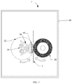
- FIG. 1 is a schematic top view of one embodiment of the present application of a sliding sheet
- FIG. 2 is a flow chart of an embodiment of the present application of a method for manufacturing the sliding sheet
- FIG. 3 is a schematic top view of the embodiment of the present application of the method for manufacturing the sliding sheet
- FIG. 4 is a flow chart of another embodiment of the present application of the method for manufacturing the sliding sheet
- FIG. 5 is a flow chart of yet another embodiment of the present application of the method for manufacturing the sliding sheet
- FIG. 6 is a schematic side view of a fabric layer of another embodiment of the present application of the sliding sheet.
- FIG. 7 is a schematic side view of an embodiment of the present application of a fixing device
- FIG. 8 is a schematic view of an embodiment of the present application of a distribution of a lubricant in a relative movement between the sliding sheet and the endless fixing belt;
- FIG. 9 is a schematic top view of a method for manufacturing a sliding sheet in related art.
- FIG. 10 is a schematic view of a distribution of a lubricant in a relative movement between a sliding sheet and an endless fixing belt in related art
- FIG. 11 is a schematic side view of an embodiment of the present application of an image forming apparatus.
- an embodiment of the present application provides a sliding sheet 10 including one or more fabric layers 100 .
- the sliding sheet 10 has a length direction and a width direction.
- the fabric layer 100 includes a plurality of warp yarns 110 and a plurality of weft yarns 120 .
- the plurality of warp yarns 110 are interlaced with the plurality of weft yarns 120 .
- the sliding sheet 10 has a first edge 12 , the first edge 12 extends in the length direction of the sliding sheet 10 , and the plurality of warp yarns 110 are bent toward a middle portion of the first edge 12 .
- the plurality of warp yarns 110 are substantially parallel to each other.
- the sliding sheet 10 can further have a second edge 14 .
- the second edge 14 extends in the length direction of the sliding sheet 10 , and the first edge 12 is opposite to the second edge 14 .
- the first edge 12 and the second edge 14 can also be the edges of the fabric layer 100 .
- the plurality of weft yarns 120 can diverge (or radially extend) from the middle portion of the first edge 12 to the second edge 14 such that a distance near the first edge 12 is less than the distance near the second edge 14 between adjacent weft yarns 120 .
- An angle between the weft yarn 120 and the first edge 12 can be gradually changed in different weft yarns 120 .
- the angle between the weft yarn 120 located at the middle portion of the first edge 12 and the first edge 12 can be substantially 90 degrees. The closer the weft yarn 120 to the end of the first edge 12 , the smaller the angle between the weft yarn 120 and the first edge 12 .
- the warp yarns 110 refer to the yarns extending substantially along the length direction of the sliding sheet 10
- the weft yarns 120 refer to the yarns substantially extending from the first edge 12 to the second edge 14 of the sliding sheet 10 .
- the warp yarns 110 and/or the weft yarns 120 are not limited to be straight or strictly extended in a certain direction.
- the manner in which the plurality of warp yarns 110 interlace with the plurality of weft yarns 120 can be, but is not limited to, a warp yarn 110 alternatively pass the plurality of weft yarns 120 from the two opposite surfaces of the fabric layer 100 , and a weft yarn 120 alternatively pass the plurality of warp yarns 120 from the two opposite surfaces of the fabric layer 100 , so as to weave the plurality of warp yarns 110 together with the plurality of weft yarns 120 .
- the warp yarn 110 is bent toward the middle portion of the first edge 12 such that a portion of the warp yarn 110 farthest from the first edge 12 is located at the middle portion of the sliding sheet 10 in the length direction, and a portion of the warp yarn 110 closest to the first edge 12 is located at two ends of the sliding sheet 10 in the length direction.
- the sliding sheet 10 can have a length of about 100 mm to about 500 mm and a width of about 5 mm to about 200 mm.
- the middle portion of the first edge 12 can be a center point of the first edge 12 or a central section taking 1% to 10% of the length of the first edge 12 .
- the two ends of the warp yarn 110 are closer to the first edge 12 , and the middle of the warp yarn 110 is farther to the first edge 12 .
- two ends of at least one warp yarn 110 are located on the first edge 12 .
- the plurality of warp yarns 110 can be arcuate (e.g., have an arch shape).
- a height of the arch h is defined as a shortest distance from an apex of the arch to a line connecting the two ends of the warp yarn 110 . In one embodiment, h is in a range from about 0.3 mm to about 15 mm.
- an axis of symmetry x is defined in the plane of the fabric layer 100 .
- the axis of symmetry x is substantially perpendicular to the first edge 12 and passes through the center of the first edge 12 .
- Each warp yarn 110 can have a symmetrical shape about the axis of symmetry x.
- the plurality of weft yarns 120 can be symmetrically distributed about the axis of symmetry.
- An angle between each of the plurality of weft yarns 120 and the axis of symmetry x can be in a range from 0 degrees to 90 degrees, in some embodiments be in a range from 0 degrees to 60 degrees, and in some embodiments be in a range from 0 degrees to 30 degrees. The angle can be gradually getting larger from the center to the two ends of the first edge 120 .
- the fabric layer 100 can further include a plurality of truncated yarns 130 located at the second edge 14 .
- the truncated yarns 130 are a portion of the warp yarns 110 which are truncated by the second edge 14 , the truncated yarns 130 are cut from the warp yarns along the second edge 14 and located within the fabric layer 100 .
- a material of the warp yarns 110 and the weft yarns 120 withstand a working temperature, for example, equal to or greater than 80° C., and in one embodiment in a range of 160° C. to 260° C.
- the material of the warp yarns 110 and the weft yarns 120 can be selected from, but not limited to, at least one of polytetrafluoroethylene and polyphenylene sulfide.
- a thickness of the sliding sheet 10 can be in a range from 0.2 mm to 1 mm.
- the present application further provides an embodiment of a method for manufacturing the sliding sheet 10 , the method includes:
- step S 12 adjusting a tension for weaving the auxiliary yarn 16 into the fabric raw layer 200 during the weaving of step S 11 , so that the tension of the auxiliary yarn 16 is greater than the tension of the plurality of warp yarns 110 , thereby bending the plurality of warp yarns 110 in the fabric raw layer 200 toward the auxiliary yarn 16 ;
- step S 11 all of the warp yarns 110 can have the same material and elasticity.
- step S 12 the tension of the auxiliary yarn 16 can be increased to produce a tightening effect on the plurality of weft yarns 120 , thereby bending the plurality of warp yarns 110 toward the auxiliary yarn 16 so as to result an overall bending effect of the fabric raw layer 200 toward the auxiliary yarn 16 .
- the plurality of weft yarns 120 can be simultaneously divergent or radially extended.
- step S 13 the bent warp yarns 110 and the radially extended weft yarns 120 are fixed in shape by heating the fabric raw layer 200 .
- step S 14 the cutting can remove the auxiliary yarn 16 and form the first edge 12 which is the edge of the fabric layer 110 that near the auxiliary yarn 16 .
- the present application further provides an embodiment of the method for manufacturing the sliding sheet, and the method includes:
- the same pulling force can be used during the weaving of the auxiliary yarn 16 and the warp yarns 110 woven into the fabric raw layer 200 , but the auxiliary yarn 16 has a greater elasticity than the warp yarns 110 , thereby bending the yarns 110 toward the auxiliary yarn 16 , so as to result an overall bending effect of the fabric raw layer 200 toward the auxiliary yarn 16 .
- the plurality of weft yarns 120 can be simultaneously divergent or radially extended.
- the bent warp yarns 110 and the radially extended weft yarns 120 are fixed in shape by heating the fabric raw layer 200 .
- the cutting can remove the auxiliary yarn 16 and form the first edge 12 which is the edge of the fabric layer 110 that near the auxiliary yarn 16 .
- the present application further provides an embodiment of the method for manufacturing the sliding sheet, the method includes:
- all of the warp yarns 110 can have the same elasticity and the same tension during weaving into the fabric original layer, so that the warp yarns 110 and a third edge 16 of the fabric original layer obtained in step S 31 can be substantially straight rather than curved or arcuate.
- the warp yarns 110 are thermally shrunk by locally heating of the fabric original layer. The closer to the heating center, the greater of the shrinkage of the warp yarns 110 , and the greater of the pulling force toward the center. The father from the heating center, the smaller of the shrinkage of the warp yarns 110 , and the smaller of the pulling force toward the center.
- the warp yarns 110 are bent toward the localized area that is heated, so as to result a bending effect of the fabric raw layer 200 toward the localized area that is heated.
- the localized area that is heated can be located at one edge of the fabric original layer that is substantially parallel to the warp yarns 110 .
- the fabric raw layer 200 is bent toward the edge.
- the heating temperature can be greater than a working temperature of the sliding sheet 10 , for example, greater than 80° C. to 260° C.
- the first edge 12 of the fabric layer 110 obtained from the cutting can pass through the localized area that is heated, and the localized area can be located at the middle portion of the first edge 12 .
- the fabric raw layer 200 can have one edge, and the warp yarns 110 can be bent toward the center of the edge.
- the fabric raw layer 200 can be cut into desired shapes of the fabric layer 100 , for example, is cut along a straight line so that the fabric layer 100 has a straight first edge 12 .
- the embodiments of the above-described manufacturing method can further include demarcating a cutting area 18 on the fabric raw layer 200 and cutting along a boundary of the cutting area 18 to obtain the fabric layer 100 .
- the shape of the cutting area 18 corresponds to the shape of the fabric layer 100 .
- the cutting area 18 can be a rectangular area.
- the plurality of weft yarns 120 can diverge.
- the above-described embodiments of the manufacturing method can further include adjusting a weaving direction of the plurality of weft yarns 120 so that the weft yarns 120 are radially extended.
- the present application further provides another embodiment of the sliding sheet 10 including a first fabric layer 102 and a second fabric layer 104 stacked with each other, each having the same structure as the fabric layer 100 .
- the first fabric layer 102 includes a plurality of first warp yarns 112 and a plurality of first weft yarns 122 , and the plurality of first warp yarns 112 are interlaced with the plurality of first weft yarns 122 .
- the second fabric layer 104 includes a plurality of second warp yarns 114 and a plurality of second weft yarns 124 , and the plurality of second warp yarns 114 are interlaced with the plurality of second weft yarns 124 .
- the plurality of second warp yarns 114 pass over one or more first weft yarns 122 from a surface of the first fabric layer 102 remote from the second fabric layer 104 , and pass over one or more second weft yarns 124 from a surface of the second fabric layer 104 remote from the first fabric layer 102 .
- the sliding sheet 10 has a first edge 12 extending along the length direction of the sliding sheet 10 , and the plurality of first warp yarns 112 are bent toward the middle portion of the first edge 12 ; and/or the plurality of second warp yarns 114 are bent toward the middle portion of the first edge 12 .
- the plurality of first warp yarns 112 and/or the plurality of second warp yarns 114 can be arcuate (e.g., have an arch shape).
- the sliding sheet 10 can further have a second edge 14 extending along the length direction of the sliding sheet 10 .
- the first edge 12 is opposite to the second edge 14 .
- the first edge 12 and the second edge 14 can also be the edges of the first fabric layer 102 and the second fabric layer 104 .
- the plurality of first weft yarns 122 can diverge (or radially extend) from the middle portion of the first edge 12 to the second edge 14 and/or the plurality of second weft yarns 124 can diverge (or radially extend) from the middle portion of the first edge 12 to the second edge 14 .
- an axis of symmetry x is defined in the plane of the first fabric layer 102 and the second fabric layer 104 .
- the axis of symmetry x is substantially perpendicular to the first edge 12 and passes through the center of the first edge 12 .
- Each first warp yarn 122 can have a symmetrical shape about the axis of symmetry x.
- Each second warp yarn 124 can have a symmetrical shape about the axis of symmetry x.
- the plurality of first weft yarns 122 can be symmetrically distributed about the axis of symmetry x.
- the plurality of second weft yarns 124 can be symmetrically distributed about the axis of symmetry x.
- An angle between each of the plurality of first weft yarns 122 and/or the plurality of second weft yarns 124 and the axis of symmetry x can be in a range from 0 degrees to 30 degrees.
- the first fabric layer 102 and/or the second fabric layer 104 further includes a plurality of truncated yarns 130 at the second edge 14 .
- the truncated yarns 130 are a portion of the first warp yarns 112 and/or the second warp yarns 114 which are truncated by the second edge 14 , the truncated yarns 130 are cut from the first and/or second warp yarns 112 , 114 along the second edge 14 and located within the first and/or second fabric layers 102 , 104 .
- the present application further provides an embodiment of the method for manufacturing the sliding sheet 10 , the method includes:
- step S 43 in the process of the step S 41 and/or the step S 42 , adjusting a tension for weaving the first auxiliary yarn into the first fabric raw layer so that the tension of the first auxiliary yarn is greater than the tension of the plurality of first warp yarns 112 , thereby bending the plurality of first warp yarns 112 in the first fabric raw layer toward the first auxiliary yarn, and/or adjusting the tension for weaving the second auxiliary yarn into the second fabric raw layer so that the tension of the second auxiliary yarn is greater than the tension of the plurality of second warp yarns 114 , thereby bending the plurality of second warp yarns 114 in the second fabric raw layer toward the second auxiliary yarn;
- the present application further provides another embodiment of the method for manufacturing the sliding sheet 10 , the method includes:
- the present application further provides yet another embodiment of the method for manufacturing the sliding sheet 10 , the method includes:
- the present application further provides an embodiment of a fixing device 50 including the sliding sheet 10 .
- the fixing device 50 can further include a pressure roller 20 as a driving roller and a heating roller 30 as a driven roller.
- the heating roller 30 includes an endless fixing belt 32 , a heat source 34 and a supporting member 36 disposed inside a loop formed by the endless fixing belt 32 .
- the heat source 34 is configured for heating the endless fixing belt 32 .
- the support member 36 is configured for supporting the sliding sheet 10 .
- the sliding sheet 10 is provided between the support member 36 and the endless fixing belt 32 .
- the sliding sheet 10 is provided on a side of a portion of the endless fixing belt 32 that is closest to the pressure roller 20 .
- the sliding sheet 10 is capable of supporting the endless fixing belt 32 so that a pressing force can be applied between the pressure roller 20 and the endless fixing belt 32 .
- a recording medium 1 (for example, paper) carries an unfixed image formed by a toner (for example, carbon particles) is conveyed to the pressure roller 20 and the heating roller 30 of the fixing device.
- the pressure roller 20 rotates and drives the endless fixing belt 32 of the heating roller 30 to rotate therewith such that the recording medium 1 passes between the pressure roller 20 and the endless fixing belt 32 of the heating roller 30 , heated and pressed, thereby having the toner fixed on the surface of the recording medium 1 .
- the endless fixing belt 32 moves relative to the supporting member 36 and the sliding sheet 10 which are stationary.
- a lubricant is provided on the surface of the sliding sheet 10 to reduce a friction resistance between the supporting member 36 and the endless fixing belt 32 , thereby alleviating a frictional loss caused by a long-term use of the endless fixing belt 32 and preventing the endless fixing belt 32 from breaking.
- the length direction of the sliding sheet 10 is perpendicular to the rotating direction of the endless fixing belt 32 , and the endless fixing belt 32 rotates from the second edge 14 to the first edge 12 .
- the lubricant 3 flows out from the first edge 12 and is coated on the inner surface of the endless fixing belt 32 .
- the lubricant 3 infiltrated in the fabric layer tends to be guided by the warp yarns 110 to be aggregated toward the middle portion of the first edge 12 during the rotation of the endless fixing belt 32 relative to the sliding sheet 10 .
- the lubricant 3 coated on the inner surface of the endless fixing belt 32 is capable of being retrieved by the second edge 14 of the sliding sheet 10 after a round of the rotation of the endless fixing belt 32 . Accordingly, the sliding sheet 10 can keep the original amount of lubricant 3 in a better level in a long service life, the service life of the endless fixing belt 32 can be increased.
- the plurality of weft yarns 120 diverging from the middle portion of the first edge 12 to the second edge 14 also contribute to the aggregation of the lubricant 3 toward the middle portion of the first edge 12 .
- the lubricant 3 does not have directivity when flowing out from the first edge 12 and easily leaks from both ends of the sliding sheet 10 in the length direction due to the diffusibility of the liquid.
- the endless fixing belt 32 rotates a round relative to the sliding sheet 10 , the lubricant 3 that are leaked from the ends is hard to be recovered by the second edge 14 of the sliding sheet 10 .
- a problem of gradually losing of the lubricant 3 from the sliding sheet 10 exists in a long-term use.
- the present application further provides an embodiment of an image forming apparatus 1 including a fixing device 50 .
- the image forming apparatus is a printer, a copier, or a facsimile.
Landscapes
- Engineering & Computer Science (AREA)
- Textile Engineering (AREA)
- Physics & Mathematics (AREA)
- General Physics & Mathematics (AREA)
- Woven Fabrics (AREA)
- Fixing For Electrophotography (AREA)
Abstract
Description
Claims (11)
Applications Claiming Priority (1)
| Application Number | Priority Date | Filing Date | Title |
|---|---|---|---|
| CNPCT/CN2017/011364 | 2017-11-29 |
Related Parent Applications (2)
| Application Number | Title | Priority Date | Filing Date |
|---|---|---|---|
| CNPCT/CN2017/011364 Continuation-In-Part | 2017-11-29 | 2017-11-29 | |
| CNPCT/CN2017/011364 Continuation | 2017-11-29 | 2017-11-29 |
Publications (2)
| Publication Number | Publication Date |
|---|---|
| US20190163102A1 US20190163102A1 (en) | 2019-05-30 |
| US10895833B2 true US10895833B2 (en) | 2021-01-19 |
Family
ID=66632291
Family Applications (1)
| Application Number | Title | Priority Date | Filing Date |
|---|---|---|---|
| US15/871,143 Active 2038-12-06 US10895833B2 (en) | 2017-11-29 | 2018-01-15 | Sliding sheet and method for manufacturing the same |
Country Status (1)
| Country | Link |
|---|---|
| US (1) | US10895833B2 (en) |
Families Citing this family (2)
| Publication number | Priority date | Publication date | Assignee | Title |
|---|---|---|---|---|
| JP7069921B2 (en) * | 2018-03-26 | 2022-05-18 | 株式会社リコー | Fixing device and image forming device |
| JP7451979B2 (en) * | 2019-12-10 | 2024-03-19 | 株式会社リコー | Fixing device and image forming device |
Citations (10)
| Publication number | Priority date | Publication date | Assignee | Title |
|---|---|---|---|---|
| US5303008A (en) | 1992-06-08 | 1994-04-12 | Eastman Kodak Company | Seal-forming device for a toner receiving aperture |
| JP2002357960A (en) | 2001-06-01 | 2002-12-13 | Canon Inc | Image forming device |
| US20040198119A1 (en) * | 2001-01-12 | 2004-10-07 | Kiyoyuki Narumi | Spiral woven fabric and high-speed rotating body using it |
| US20070079886A1 (en) * | 2002-04-10 | 2007-04-12 | Rongde Ge | Method for weaving curved warp yarns and a woven fabric |
| JP5395514B2 (en) | 2009-05-27 | 2014-01-22 | 京セラドキュメントソリューションズ株式会社 | Image forming apparatus provided with fixing guide sheet |
| CN103941565A (en) | 2013-01-21 | 2014-07-23 | 富士施乐株式会社 | Sliding member for fixing device, fixing device, and image forming apparatus |
| CN104007644A (en) | 2013-02-25 | 2014-08-27 | 株式会社理光 | Fixing device and image forming apparatus with same |
| JP2015030959A (en) | 2013-08-07 | 2015-02-16 | 株式会社豊田自動織機 | Woven fabric, and fiber bundle and fiber-reinforced composite material for composing woven fabric |
| CN205691942U (en) | 2016-06-15 | 2016-11-16 | 苏州市创怡盛实业有限公司 | Wiper |
| JP2017005662A (en) | 2015-06-16 | 2017-01-05 | 富士通株式会社 | Monitoring device |
-
2018
- 2018-01-15 US US15/871,143 patent/US10895833B2/en active Active
Patent Citations (10)
| Publication number | Priority date | Publication date | Assignee | Title |
|---|---|---|---|---|
| US5303008A (en) | 1992-06-08 | 1994-04-12 | Eastman Kodak Company | Seal-forming device for a toner receiving aperture |
| US20040198119A1 (en) * | 2001-01-12 | 2004-10-07 | Kiyoyuki Narumi | Spiral woven fabric and high-speed rotating body using it |
| JP2002357960A (en) | 2001-06-01 | 2002-12-13 | Canon Inc | Image forming device |
| US20070079886A1 (en) * | 2002-04-10 | 2007-04-12 | Rongde Ge | Method for weaving curved warp yarns and a woven fabric |
| JP5395514B2 (en) | 2009-05-27 | 2014-01-22 | 京セラドキュメントソリューションズ株式会社 | Image forming apparatus provided with fixing guide sheet |
| CN103941565A (en) | 2013-01-21 | 2014-07-23 | 富士施乐株式会社 | Sliding member for fixing device, fixing device, and image forming apparatus |
| CN104007644A (en) | 2013-02-25 | 2014-08-27 | 株式会社理光 | Fixing device and image forming apparatus with same |
| JP2015030959A (en) | 2013-08-07 | 2015-02-16 | 株式会社豊田自動織機 | Woven fabric, and fiber bundle and fiber-reinforced composite material for composing woven fabric |
| JP2017005662A (en) | 2015-06-16 | 2017-01-05 | 富士通株式会社 | Monitoring device |
| CN205691942U (en) | 2016-06-15 | 2016-11-16 | 苏州市创怡盛实业有限公司 | Wiper |
Also Published As
| Publication number | Publication date |
|---|---|
| US20190163102A1 (en) | 2019-05-30 |
Similar Documents
| Publication | Publication Date | Title |
|---|---|---|
| EP2053472A1 (en) | Fusing Device and Image Forming Apparatus Having the Same | |
| US8195072B2 (en) | Sliding sheet for fixing devices, manufacturing method for same, fixing device, and image forming apparatus | |
| US10429782B2 (en) | Fixing device having a preventing member that prevents folding of an end portion of a film | |
| JP6594043B2 (en) | Fixing device | |
| US6792236B2 (en) | Fixing device for an image forming apparatus | |
| US10895833B2 (en) | Sliding sheet and method for manufacturing the same | |
| JP2018116104A (en) | Fixation device and image formation apparatus | |
| JP2005242111A (en) | Fixing device | |
| US20140029995A1 (en) | Sheet cooling apparatus and image forming apparatus | |
| JP7081314B2 (en) | Fixing device and image forming device | |
| JP2010282237A (en) | Electrophotographic system fixing device and image forming apparatus | |
| US11474461B2 (en) | Fixing device with nip forming member having guide portions | |
| CN107991848B (en) | Slide sheet and preparation method thereof | |
| US20230297016A1 (en) | Nip forming device, fixing device, and image forming apparatus | |
| JP7305962B2 (en) | image forming device | |
| JP4577456B2 (en) | Fixing device and image forming apparatus for electrophotographic system | |
| JP4677304B2 (en) | Image heating device | |
| JP2019191248A (en) | Fixation device and image formation apparatus | |
| JP2018097072A (en) | Pressing pad, fixation device and image formation apparatus using the same | |
| WO2019104550A1 (en) | Slider and preparation method therefor | |
| JP4355165B2 (en) | Endless belt | |
| CN207636930U (en) | Sliding sheet | |
| EP4194955A1 (en) | Nip forming device and image forming apparatus | |
| JP2019082733A (en) | Image heating device | |
| JP6402898B2 (en) | Belt device, belt fixing device, and image forming apparatus |
Legal Events
| Date | Code | Title | Description |
|---|---|---|---|
| AS | Assignment |
Owner name: SHENZHEN FANCY CREATION INDUSTRIAL LIMITED, CHINA Free format text: ASSIGNMENT OF ASSIGNORS INTEREST;ASSIGNORS:YANG, MINGFU;JIN, GANG;REEL/FRAME:044616/0366 Effective date: 20180111 |
|
| FEPP | Fee payment procedure |
Free format text: ENTITY STATUS SET TO UNDISCOUNTED (ORIGINAL EVENT CODE: BIG.); ENTITY STATUS OF PATENT OWNER: LARGE ENTITY |
|
| STPP | Information on status: patent application and granting procedure in general |
Free format text: DOCKETED NEW CASE - READY FOR EXAMINATION |
|
| STPP | Information on status: patent application and granting procedure in general |
Free format text: NON FINAL ACTION MAILED |
|
| STPP | Information on status: patent application and granting procedure in general |
Free format text: RESPONSE TO NON-FINAL OFFICE ACTION ENTERED AND FORWARDED TO EXAMINER |
|
| STPP | Information on status: patent application and granting procedure in general |
Free format text: NOTICE OF ALLOWANCE MAILED -- APPLICATION RECEIVED IN OFFICE OF PUBLICATIONS |
|
| STPP | Information on status: patent application and granting procedure in general |
Free format text: PUBLICATIONS -- ISSUE FEE PAYMENT VERIFIED |
|
| STCF | Information on status: patent grant |
Free format text: PATENTED CASE |
|
| MAFP | Maintenance fee payment |
Free format text: PAYMENT OF MAINTENANCE FEE, 4TH YEAR, LARGE ENTITY (ORIGINAL EVENT CODE: M1551); ENTITY STATUS OF PATENT OWNER: LARGE ENTITY Year of fee payment: 4 |