JP7081314B2 - Fixing device and image forming device - Google Patents
Fixing device and image forming device Download PDFInfo
- Publication number
- JP7081314B2 JP7081314B2 JP2018109394A JP2018109394A JP7081314B2 JP 7081314 B2 JP7081314 B2 JP 7081314B2 JP 2018109394 A JP2018109394 A JP 2018109394A JP 2018109394 A JP2018109394 A JP 2018109394A JP 7081314 B2 JP7081314 B2 JP 7081314B2
- Authority
- JP
- Japan
- Prior art keywords
- fixing
- low friction
- base material
- warp
- sliding
- Prior art date
- Legal status (The legal status is an assumption and is not a legal conclusion. Google has not performed a legal analysis and makes no representation as to the accuracy of the status listed.)
- Active
Links
Images


Classifications
-
- G—PHYSICS
- G03—PHOTOGRAPHY; CINEMATOGRAPHY; ANALOGOUS TECHNIQUES USING WAVES OTHER THAN OPTICAL WAVES; ELECTROGRAPHY; HOLOGRAPHY
- G03G—ELECTROGRAPHY; ELECTROPHOTOGRAPHY; MAGNETOGRAPHY
- G03G15/00—Apparatus for electrographic processes using a charge pattern
- G03G15/20—Apparatus for electrographic processes using a charge pattern for fixing, e.g. by using heat
- G03G15/2003—Apparatus for electrographic processes using a charge pattern for fixing, e.g. by using heat using heat
- G03G15/2014—Apparatus for electrographic processes using a charge pattern for fixing, e.g. by using heat using heat using contact heat
- G03G15/2053—Structural details of heat elements, e.g. structure of roller or belt, eddy current, induction heating
- G03G15/2057—Structural details of heat elements, e.g. structure of roller or belt, eddy current, induction heating relating to the chemical composition of the heat element and layers thereof
-
- G—PHYSICS
- G03—PHOTOGRAPHY; CINEMATOGRAPHY; ANALOGOUS TECHNIQUES USING WAVES OTHER THAN OPTICAL WAVES; ELECTROGRAPHY; HOLOGRAPHY
- G03G—ELECTROGRAPHY; ELECTROPHOTOGRAPHY; MAGNETOGRAPHY
- G03G15/00—Apparatus for electrographic processes using a charge pattern
- G03G15/20—Apparatus for electrographic processes using a charge pattern for fixing, e.g. by using heat
- G03G15/2003—Apparatus for electrographic processes using a charge pattern for fixing, e.g. by using heat using heat
- G03G15/2014—Apparatus for electrographic processes using a charge pattern for fixing, e.g. by using heat using heat using contact heat
- G03G15/2017—Structural details of the fixing unit in general, e.g. cooling means, heat shielding means
- G03G15/2028—Structural details of the fixing unit in general, e.g. cooling means, heat shielding means with means for handling the copy material in the fixing nip, e.g. introduction guides, stripping means
-
- G—PHYSICS
- G03—PHOTOGRAPHY; CINEMATOGRAPHY; ANALOGOUS TECHNIQUES USING WAVES OTHER THAN OPTICAL WAVES; ELECTROGRAPHY; HOLOGRAPHY
- G03G—ELECTROGRAPHY; ELECTROPHOTOGRAPHY; MAGNETOGRAPHY
- G03G15/00—Apparatus for electrographic processes using a charge pattern
- G03G15/20—Apparatus for electrographic processes using a charge pattern for fixing, e.g. by using heat
- G03G15/2003—Apparatus for electrographic processes using a charge pattern for fixing, e.g. by using heat using heat
- G03G15/2014—Apparatus for electrographic processes using a charge pattern for fixing, e.g. by using heat using heat using contact heat
- G03G15/2017—Structural details of the fixing unit in general, e.g. cooling means, heat shielding means
- G03G15/2025—Structural details of the fixing unit in general, e.g. cooling means, heat shielding means with special means for lubricating and/or cleaning the fixing unit, e.g. applying offset preventing fluid
-
- G—PHYSICS
- G03—PHOTOGRAPHY; CINEMATOGRAPHY; ANALOGOUS TECHNIQUES USING WAVES OTHER THAN OPTICAL WAVES; ELECTROGRAPHY; HOLOGRAPHY
- G03G—ELECTROGRAPHY; ELECTROPHOTOGRAPHY; MAGNETOGRAPHY
- G03G21/00—Arrangements not provided for by groups G03G13/00 - G03G19/00, e.g. cleaning, elimination of residual charge
- G03G21/16—Mechanical means for facilitating the maintenance of the apparatus, e.g. modular arrangements
- G03G21/1661—Mechanical means for facilitating the maintenance of the apparatus, e.g. modular arrangements means for handling parts of the apparatus in the apparatus
- G03G21/1685—Mechanical means for facilitating the maintenance of the apparatus, e.g. modular arrangements means for handling parts of the apparatus in the apparatus for the fixing unit
-
- G—PHYSICS
- G03—PHOTOGRAPHY; CINEMATOGRAPHY; ANALOGOUS TECHNIQUES USING WAVES OTHER THAN OPTICAL WAVES; ELECTROGRAPHY; HOLOGRAPHY
- G03G—ELECTROGRAPHY; ELECTROPHOTOGRAPHY; MAGNETOGRAPHY
- G03G2215/00—Apparatus for electrophotographic processes
- G03G2215/20—Details of the fixing device or porcess
- G03G2215/2003—Structural features of the fixing device
- G03G2215/2016—Heating belt
- G03G2215/2025—Heating belt the fixing nip having a rotating belt support member opposing a pressure member
- G03G2215/2029—Heating belt the fixing nip having a rotating belt support member opposing a pressure member the belt further entrained around one or more stationary belt support members, the latter not being a cooling device
-
- G—PHYSICS
- G03—PHOTOGRAPHY; CINEMATOGRAPHY; ANALOGOUS TECHNIQUES USING WAVES OTHER THAN OPTICAL WAVES; ELECTROGRAPHY; HOLOGRAPHY
- G03G—ELECTROGRAPHY; ELECTROPHOTOGRAPHY; MAGNETOGRAPHY
- G03G2215/00—Apparatus for electrophotographic processes
- G03G2215/20—Details of the fixing device or porcess
- G03G2215/2003—Structural features of the fixing device
- G03G2215/2016—Heating belt
- G03G2215/2035—Heating belt the fixing nip having a stationary belt support member opposing a pressure member
- G03G2215/2038—Heating belt the fixing nip having a stationary belt support member opposing a pressure member the belt further entrained around one or more rotating belt support members
Description
本発明は、定着装置及び画像形成装置に関する。 The present invention relates to a fixing device and an image forming device.
加圧ローラと、加圧ローラ外表面に接触し従動回転する定着ベルトと、定着ベルト内部に配置されてニップを形成するニップ形成部材とから成るベルト摺動タイプの定着装置において、低摩擦シート(摺動シート)をニップ形成部材に保持させ、ベルト回動時の摺動摩擦を低減する技術が知られている。 In a belt sliding type fixing device consisting of a pressure roller, a fixing belt that comes into contact with the outer surface of the pressure roller and rotates drivenly, and a nip forming member arranged inside the fixing belt to form a nip, a low friction sheet ( A technique is known in which a sliding sheet) is held by a nip forming member to reduce sliding friction when the belt rotates.
しかし、従来のベルト摺動タイプの定着装置においては、ポリイミドなどの樹脂性基材から成る定着ベルトよりもガラスクロス基材から成る低摩擦シートの方が線膨張係数が小さく、熱膨張によって定着ベルトが長手方向に伸びても低摩擦シートは伸びなかった。そして、定着装置が冷えた際に定着ベルトの熱収縮によって低摩擦シートを長手方向中央部に寄せる力が生じ、定着装置の加熱と冷却を繰り返す内に低摩擦シートの中央部にシワが発生することがあった。 However, in the conventional belt sliding type fixing device, the low friction sheet made of a glass cloth base material has a smaller linear expansion coefficient than the fixing belt made of a resin base material such as polyimide, and the fixing belt is formed by thermal expansion. However, the low friction sheet did not stretch even if it stretched in the longitudinal direction. Then, when the fixing device is cooled, the heat shrinkage of the fixing belt causes a force to move the low friction sheet toward the center in the longitudinal direction, and wrinkles are generated in the center of the low friction sheet while the fixing device is repeatedly heated and cooled. There was something.
特許文献1には、定着ベルトの摺動抵抗を低く保ちつつ、潤滑剤漏れを防止するため、ニップ形成部材には潤滑剤を含浸させた織物からなる低摩擦部材を摺動部材として備え、織物の糸は編目を有する糸で構成されることが開示されている。
In
しかしながら、低摩擦部材へのシワの発生や、隣り合う縦糸どうしの距離と幅の関係などについては考慮されておらず、低摩擦部材の剛性について改善の余地がある。 However, the occurrence of wrinkles on the low friction member and the relationship between the distance and the width between adjacent warp threads are not taken into consideration, and there is room for improvement in the rigidity of the low friction member.
そこで本発明は、簡易な構成にて低摩擦部材へのシワの発生を効果的に抑制することを課題とする。 Therefore, it is an object of the present invention to effectively suppress the occurrence of wrinkles on the low friction member with a simple structure.
この課題を解決するため、回転可能に配設された加圧部材と、前記加圧部材に接触して回転する定着部材と、前記定着部材の内部に配置され、前記加圧部材からの押圧によりニップ部を形成するニップ形成部材と、前記ニップ形成部材と前記定着部材の間に設置された低摩擦部材とを備え、記録媒体上の未定着画像を前記ニップ部を通して定着させる定着装置において、前記低摩擦部材は、横糸と縦糸とを網状に編み込んで形成された基材層と、摺動摩擦低減のために前記低摩擦部材の前記定着部材との摺動面に設けられた、前記基材層とは別材質の表層と、補強と前記低摩擦部材の反り防止のために設けられた裏層とを有し、前記基材層を構成する紡績糸は樹脂繊維又は金属繊維から成り、前記定着部材の摺動方向に見た前記低摩擦部材の断面において、隣り合う前記縦糸と前記縦糸との間隔は、前記縦糸の幅方向寸法の0.4倍以下であり、且つ前記定着部材の摺動方向と垂直であって前記低摩擦部材の長手方向に見た断面において、個々の横糸の厚さ方向寸法が幅方向寸法の0.2倍以上であることを特徴とする定着装置を提案する。 In order to solve this problem, a pressurizing member rotatably arranged, a fixing member that rotates in contact with the pressurizing member, and a fixing member arranged inside the fixing member by pressing from the pressurizing member. In a fixing device including a nip forming member forming a nip portion and a low friction member installed between the nip forming member and the fixing member, an unfixed image on a recording medium is fixed through the nip portion. The low-friction member is a base material layer provided on a sliding surface between a base material layer formed by knitting weft and warp yarns in a mesh shape and the fixing member of the low-friction member in order to reduce sliding friction. It has a surface layer made of a different material from the above, and a back layer provided for reinforcement and warpage prevention of the low friction member, and the spun yarn constituting the base material layer is made of resin fiber or metal fiber and is fixed. In the cross section of the low friction member viewed in the sliding direction of the member, the distance between the warp threads adjacent to each other is 0.4 times or less the widthwise dimension of the warp threads , and the fixing member slides. We propose a fixing device characterized in that the thickness direction dimension of each weft is 0.2 times or more the width direction dimension in a cross section perpendicular to the direction and viewed in the longitudinal direction of the low friction member.
本発明によれば、低摩擦部材の基材層を構成する紡績糸と紡績糸との間隔や紡績糸の断面形状を所定の比率の範囲に設定することで、低摩擦部材自体が十分な剛性を有し、シワを生じさせる外力に抗えるため、簡易な構成にて低摩擦部材へのシワの発生を効果的に抑制することができる。 According to the present invention, by setting the distance between the spun yarns constituting the base material layer of the low friction member and the cross-sectional shape of the spun yarn within a predetermined ratio range, the low friction member itself has sufficient rigidity. Since it resists the external force that causes wrinkles, it is possible to effectively suppress the occurrence of wrinkles on the low friction member with a simple configuration.
図1は、本実施形態の画像形成装置の全体構成を示す模式図である。
画像形成装置100は、トナー像が転写された記録紙(記録媒体)Sにトナー像を定着させるための本発明の定着装置80を備えている。なお、画像形成装置100としては、図1に示すタンデム方式のプリンタに限定されず、さらにプリンタだけではなく複写機やファクシミリ装置などを対象とすることも可能である。
FIG. 1 is a schematic diagram showing the overall configuration of the image forming apparatus of the present embodiment.
The
図1に示す画像形成装置100は、イエロー、シアン、マゼンタ、ブラックの各色に色分解された色にそれぞれ対応する像としての画像を形成可能な像担持体としての感光体ドラム20Y,20C,20M,20Bkを並設したタンデム構造が採用されている。
The
各感光体ドラム20Y,20C,20M,20Bkは、A1方向の上流側からこの順で並んでいる。各感光体ドラム20Y,20C,20M,20Bkは、イエロー、シアン、マゼンタ、ブラックの画像をそれぞれ形成するための画像ステーションに備えられている。
The
各感光体ドラム20Y,20C,20M,20Bkに形成された可視像が、各感光体ドラム20Y,20C,20M,20Bkに対峙しながら矢印A1方向に移動可能な無端ベルトが用いられる中間転写体(以下、転写ベルトという)11に対して1次転写行程を実行してそれぞれの画像が重畳転写され、その後、記録シートなどが用いられる記録紙Sに対して2次転写行程を実行することで一括転写されるようになっている。
An intermediate transfer body using an endless belt in which a visible image formed on each
各感光体ドラムの周囲には、感光体ドラムの回転に従い画像形成処理するための装置が配置されている。 A device for performing image forming processing according to the rotation of the photoconductor drum is arranged around each photoconductor drum.
ブラック画像形成を行う感光体ドラム20Bkを対象として説明すると、感光体ドラム20Bkの回転方向に沿って画像形成処理を行う帯電装置30Bk,現像装置40Bk、1次転写ローラ12Bkおよびクリーニング装置50Bkが配置されている。帯電後に行われる書き込みは、光書込装置8が用いられる。
Explaining the photoconductor drum 20Bk that forms a black image as a target, a charging device 30Bk, a developing device 40Bk, a primary transfer roller 12Bk, and a cleaning device 50Bk that perform image forming processing along the rotation direction of the photoconductor drum 20Bk are arranged. ing. The
転写ベルト11に対する重畳転写は、転写ベルト11がA1方向に移動する過程において、各感光体ドラム20Y,20C,20M,20Bkに形成された可視像が、転写ベルト11の同じ位置に重ねて転写されるよう、転写ベルト11を挟んで各感光体ドラム20Y,20C,20M,20Bkに対向して配設された1次転写ローラ12Y,12C,12M,12Bkによる電圧印加によって、A1方向上流側から下流側に向けてタイミングをずらして行われる。
In the superimposed transfer to the
画像形成装置100は、色毎の画像形成処理を行う4つの画像ステーションと、各感光体ドラム20Y,20C,20M,20Bkの上方に対向して配設され、転写ベルト11及び1次転写ローラ12Y,12C,12M,12Bkを備えた転写ベルトユニット10と、転写ベルト11に対向して配設され転写ベルト11に従動し、連れ回りする転写部材としての転写ローラである2次転写ローラ5と、転写ベルト11に対向して配設され転写ベルト11上をクリーニングする中間転写ベルトクリーニング装置13と、これら4つの画像ステーションの下方に対向して配設された光書き込み装置としての光書込装置8とを有している。
The
光書込装置8は、光源としての半導体レーザ、カップリングレンズ、fθレンズ、トロイダルレンズ、折り返しミラーおよび偏向手段としての回転多面鏡などを装備しており、各感光体ドラム20Y,20C,20M,20Bkに対して色毎に対応した書き込み光Lbを出射して感光体ドラム20Y,20C,20M,20Bkに静電潜像を形成する構成とされている。
The
画像形成装置100は、感光体ドラム20Y,20C,20M,20Bkと転写ベルト11との間に向けて搬送される記録紙Sを積載した給紙カセットとしてのシート給送装置61と、シート給送装置61から搬送されてきた記録紙Sを、画像ステーションによるトナー像の形成タイミングに合わせた所定のタイミングで、各感光体ドラム20Y,20C,20M,20Bkと転写ベルト11との間の転写部に向けて繰り出すレジストローラ対4と、記録紙Sの先端がレジストローラ対4に到達したことを検知するセンサとを備えている。
The
画像形成装置100は、さらに、本発明の定着装置80によりトナー像を定着させた定着済みの記録紙Sを画像形成装置100の本体外部に排出する排出ローラ7と、画像形成装置100の本体上部に配設されて排出ローラ7により画像形成装置100の本体外部に排出された記録紙Sを積載する排紙トレイ17と、排紙トレイ17の下側に位置し、イエロー、シアン、マゼンタ、ブラックの各色のトナーを充填されたトナーボトル9Y,9C,9M,9Bkとを備えている。
The
転写ベルトユニット10は、転写ベルト11、1次転写ローラ12Y,12C,12M,12Bkの他に、転写ベルト11が掛け回されている駆動ローラ72及び従動ローラ73を有している。
The
従動ローラ73は、転写ベルト11に対する張力付勢手段としての機能も備えており、このため、従動ローラ73には、バネなどを用いた付勢手段が設けられている。このような転写ベルトユニット10と、1次転写ローラ12Y,12C,12M,12Bkと、2次転写ローラ5と、クリーニング装置13とで転写装置71が構成されている。
The driven
シート給送装置61は、画像形成装置100の本体下部に配設されており、最上位の記録紙Sの上面に当接する給紙ローラとしての給送ローラ3を有しており、給送ローラ3が反時計回り方向に回転駆動されることにより、最上位の記録紙Sをレジストローラ対4に向けて給送するようになっている。
The
転写装置71に装備されているクリーニング装置13は、詳細な図示を省略するが、転写ベルト11に対向、当接するように配設されたクリーニングブラシとクリーニングブレードとを有しており、転写ベルト11上の残留トナー等の異物をクリーニングブラシとクリーニングブレードとにより掻き取り、除去して、転写ベルト11をクリーニングするようになっている。クリーニング装置13は、さらに、転写ベルト11から除去した残留トナーを搬出し廃棄するための排出手段を有している。
Although not shown in detail, the
次に、図2を用いて画像形成装置100に設置される定着装置80の構成について詳述する。
本実施形態の定着装置80は、回転可能に配設された加圧部材であるローラ部材83と、ローラ部材83に接触して従動回転する定着部材である無端ベルト81と、無端ベルト81の内部に配置され、無端ベルト81を介してローラ部材83と圧接してニップ部Nを形成するニップ形成部材86と、ニップ形成部材86と無端ベルト81との間に配設される低摩擦部材である摺動シート90と、を少なくとも備え、記録紙S上の未定着画像をニップ部Nを通して定着させる。
Next, the configuration of the
The
図2に示す例では、定着装置80は、回転可能なローラ部材(「加圧ローラ」ともいう)83と、無端ベルト(「定着ベルト」ともいう)81を有し、無端ベルト81はハロゲンヒータ等の熱源82により内周側から直接加熱される。
In the example shown in FIG. 2, the
図2に示す例では、ニップ部Nの形状は平坦状であるが、凹形状やその他の形状であっても良い。ニップ部Nの形状は、凹形状の方が、記録紙の先端の排出方向がローラ部材83寄りになり、記録紙Sが無端ベルト81から容易に分離されるのでジャムの発生が抑制される。
In the example shown in FIG. 2, the shape of the nip portion N is flat, but it may be concave or other. As for the shape of the nip portion N, in the concave shape, the discharge direction of the tip of the recording paper is closer to the
無端ベルト81は、ニッケルやSUSなどの金属ベルトやポリイミドなどの樹脂材料を用いた無端ベルト(もしくはフィルム)とする。ベルトの表層はPFA(Tetra fluoro ethylene-perfluoro Alkylvinyl ether copolymer)又はPTFE(Poly Tetra Fluoro Ethylene)層などの離型層を有し、トナーが付着しないように離型性を持たせている。ベルトの基材とPFA又はPTFE層の間にはシリコーンゴムの層などで形成する弾性層があっても良い。シリコーンゴム層がない場合は熱容量が小さくなり、定着性が向上するが、未定着画像を押し潰して定着させるときにベルト表面の微小な凹凸が画像に転写されて画像のベタ部にユズ肌状の光沢ムラ(ユズ肌画像)が残るという不具合が生じる。これを改善するにはシリコーンゴム層を100[μm]以上設ける必要がある。シリコーンゴム層の変形により、微小な凹凸が吸収されユズ肌画像が改善する。
The
無端ベルト81の内部には、ニップ部Nを支持するための支持部材(ステー)87を設け、ローラ部材83により圧力を受けるニップ形成部材86の撓みを防止し、軸方向で均一なニップ幅を得られるようにしている。
A support member (stay) 87 for supporting the nip portion N is provided inside the
この支持部材87は、両端部で保持部材(フランジ)88に保持固定され位置決めされている。熱源82と支持部材87の間に反射部材89を備え、熱源82からの輻射熱などにより支持部材87が加熱されてしまうことによる無駄なエネルギー消費を抑制している。反射部材89を備える代わりに支持部材87表面に断熱もしくは鏡面処理を行っても同様の効果を得ることか可能となる。熱源82としては、本実施形態ではハロゲンヒータを用いているが、IH、抵抗発熱体、カーボンヒータ等であっても良い。
The
ローラ部材83は芯金85の外周に弾性層84を有し、離型性を得るために表面に離型層(PFA又はPTFE層)が設けられている。芯金85は、ローラ部材83の中心に配置される部材であり、回転可能となっている。
ローラ部材83は画像形成装置100に設けられたモータなどの駆動源からギヤを介して駆動力が伝達され回転する。
The
The
ローラ部材83は、スプリングなどにより無端ベルト81側に押し付けられており、弾性層84が押し潰されて変形することにより、所定のニップ部Nを形成している。
ローラ部材83は中空のローラであっても良く、内部に熱源82を有していても良い。弾性層84はソリッドゴムでも良いが、ローラ部材83内部に熱源82が無い場合は、スポンジゴムを用いても良い。スポンジゴムの方が、断熱性が高まり定着ベルトの熱が奪われにくくなるので、より好ましい。
The
The
無端ベルト81はローラ部材83により連れ回り回転する。
図2の例では、ローラ部材83が、画像形成装置100に備えられた駆動源により回転し、ニップ部Nでベルトに駆動力が伝達されることにより無端ベルト81が回転する。無端ベルト81はニップ部Nで挟み込まれて回転し、ニップ部N以外では両端部で保持部材88にガイドされて走行する。
このような構成により安価で、昇温が速い定着装置を実現することが可能となる。
The
In the example of FIG. 2, the
With such a configuration, it is possible to realize a fixing device that is inexpensive and has a high temperature rise.
なお、定着装置の構成としては、図2に示すものに限定されず、例えば、ローラ部材が定着部材(定着ローラ)として機能し、無端ベルトが加圧部材として機能する態様であってもよい。この場合においても、摺動シートは無端ベルトの内側に配置され、ニップ形成部材と無端ベルトとの間に設けられる。 The configuration of the fixing device is not limited to that shown in FIG. 2, and for example, a roller member may function as a fixing member (fixing roller) and an endless belt may function as a pressure member. Also in this case, the sliding sheet is arranged inside the endless belt and is provided between the nip forming member and the endless belt.
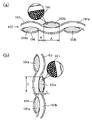
図3は、第1実施形態に係る摺動シートを示す概略斜視図である。図4(a)は、図3の矢印X方向から見た摺動シートの概略断面図、図4(b)は、図3の矢印Y方向から見た摺動シートの概略断面図である。
図3に示すように本実施形態では、ニップ形成部材86は、矢印sで示される無端ベルト81の回転方向及び摺動方向上流側に複数の突起部86aを有している。突起部86aは、ニップ形成部材86の底部から下方に延在した後、ローラ部材83とは反対方向に屈曲しており、断面L形を有している。また、摺動シート90の下部は、これらの突起部86aに対応する位置に設けられた複数の穴90aを有しており、突起部86aがこれらの穴90aに挿入されることで摺動シート90がL形の突起部86aに引っ掛けられている。このような簡単な保持手段により、摺動シート90はニップ部Nを形成するニップ形成部材86の側面86bに当接した状態で保持される。
FIG. 3 is a schematic perspective view showing a sliding sheet according to the first embodiment. 4 (a) is a schematic cross-sectional view of the sliding sheet seen from the arrow X direction of FIG. 3, and FIG. 4 (b) is a schematic cross-sectional view of the sliding sheet seen from the arrow Y direction of FIG.
As shown in FIG. 3, in the present embodiment, the
なお、図3においてニップ形成部材86は5つの突起部86aを有しているが、突起部86aは5箇所に限定されず、設計者が必要な個数の突起部86aを適宜配置することが可能である。摺動シート90の保持構成をこのように簡略化できるのは、摺動シート90自体の剛性が高く、摺動シート90が外力に耐え得る構造を有しているためである。
Although the
図4(a)は、図3の矢印Xの方向から見た摺動シート90の断面図である。
本実施形態においては、1本の糸が、繊維を編まずにガラス繊維101を数十~数百本紡績することで(束ねることで)形成されている。摺動シート90は、横糸102aと縦糸102bとを網状に編み込んで形成された基材層102と、摺動摩擦低減のためにPTFEなどの材質から成る表層103、さらに補強と摺動シート90の反り防止のために設けられた裏層104から成る。ここで、摺動シート90の基材層102は織物から成る(シート状の)基材層であり、特に、繊維を編まずに紡績して得られる紡績糸を製織することで形成された基材層である。編み糸でなく紡績糸を用いることによって、高密度で強度の高い基材層102が形成され、シワが発生しにくい。
FIG. 4A is a cross-sectional view of the sliding
In the present embodiment, one thread is formed by spinning (bunching) tens to hundreds of
また図4(a)の部分拡大図に示すように、紡績糸は複数の細い繊維(本例では、ガラス繊維101)を紡績して形成される。これにより、紡績糸を細い繊維の集合体で成形するため、製織によって、曲率を有する複雑なニップ形状にも倣いやすい、しなやかな摺動シート90が作製される。また、基材層102に他の樹脂材料を含浸させる場合、紡績糸の繊維と繊維の間に空間が多いので、樹脂材料を含浸させやすい。
Further, as shown in the partially enlarged view of FIG. 4A, the spun yarn is formed by spinning a plurality of fine fibers (
前述の摺動シート90のシワは、図4(a)の縦糸102bの左右方向からの圧縮力によって隣り合う縦糸102bどうしの間隔Bの位置において横糸102aが座屈することで発生する。このため本実施形態においては、縦糸102bの幅Aに対する、隣り合う縦糸102bと縦糸102bとの距離Bの比率(B/A)を所定の比率以下となるように構成することで、横糸102aの座屈を抑制できる。
The wrinkles of the sliding
また、図4(b)には図3の矢印Yの方向から見た摺動シート90の断面図を示す。
図4(b)においては横糸102aへの圧縮力が正面方向(紙面垂直方向)に作用するため、圧縮力に抗するためには横糸102aの断面二次半径が大きいほど、シワが寄りにくいと言える。すなわち、横糸102aの幅Cに対する横糸102aの厚さDの比率(D/C)が所定比率以上であればよい。
Further, FIG. 4B shows a cross-sectional view of the sliding
In FIG. 4B, the compressive force on the
図5は、様々なB/A及びD/Cに関する実験結果を示す図である。
本発明者らはA,B,C,Dを様々に変更しながら摺動シート90のシワの発生を検証する実験を重ねた結果、図5に示す実験結果を得ることができた。これによれば、隣り合う縦糸102bどうしの距離Bの寸法は縦糸102bの幅Aの0.4倍以下(B≦0.4A)、且つ横糸102aの厚さ方向寸法Dは横糸102aの幅Cの0.2倍以上(D≧0.2C)である場合に、横糸102aの座屈が発生しにくく、摺動シート90のシワの発生が抑制されることが判明した。すなわち、無端ベルト81の摺動方向(図3の矢印s)に見た摺動シート90の断面において(図4(a))、隣り合う紡績糸(縦糸102b)と紡績糸(縦糸102b)との間隔は、紡績糸(縦糸102b)の幅方向寸法の0.4倍以下であり、且つ無端ベルト81の摺動方向(図3の矢印s)と垂直であって摺動シート90の長手方向に見た断面において(図4(b))、個々の紡績糸(横糸102a)の厚さ方向寸法がその幅方向寸法の0.2倍以上であればよい。
FIG. 5 is a diagram showing experimental results for various B / A and D / C.
As a result of repeating experiments for verifying the occurrence of wrinkles on the sliding
図5において、○は摺動シート90のシワが未発生であったことを示し、×はシワが発生したことを示し、△は軽微なシワが発生したことを示す。図の左上方に太枠で示した範囲、即ちB/A≦0.4且つD/C≧0.2の範囲においては、シワが発生しなかったことが分かる。よって、上記のようなA、B、C、Dの関係性がシワの防止に効果があることが分かった。
In FIG. 5, ◯ indicates that wrinkles were not generated in the sliding
また、図4(a),(b)に示すように、基材層102とは別材質の表層103が、摺動シート90の無端ベルト81との摺動面に設けられてもよい。表層103と基材層102を重ね合わせることで、摺動シート90の剛性が上がり、シワ防止の効果が向上される。またPTFEなどの摺動抵抗の小さな表層103を使用することにより、無端ベルト81との摩擦が小さくなり、無端ベルト81の内周面と摺動シート90の摺動面とが滑りやすくなるため、摺動シート90を座屈させようとする力を緩和することができる。
Further, as shown in FIGS. 4A and 4B, a
なお、本実施形態における摺動シート90は、基材層102、表層103及び裏層104の3層から成るが、表層103や裏層104をPTFEなどの離型性の高い樹脂で構成する場合、基材層102との親和性を上げるために表層103や裏層104と同系統の樹脂材料を基材層102に含浸させることも可能である。このような構成とすることで、基材層102が単独で用いられる場合よりも摺動シート90の剛性がさらに高められる。また表層103を用いる場合に、表層103と基材層102との接着強度を向上させることができる。
The sliding
また、本実施形態では基材層102を構成する紡績糸はガラス繊維から成る。ガラス繊維は耐熱性が高く、強度も高いので、熱や外力が作用しても変形せず、摺動シート90の元の姿勢が維持されやすい。
Further, in the present embodiment, the spun yarn constituting the
一方で、基材層102の材質はガラス繊維に限定されるものではなく、基材層102を構成する紡績糸は、例えばPTFEやPFAなどのフッ素樹脂繊維や金属製繊維等から成ってもよい。このように製織が可能な程度に柔軟性を有する繊維を、求められる材料特性に応じて適宜使用することができる。樹脂繊維又は金属繊維の耐熱性はガラス繊維のそれよりも低いが、弾性力が高くしなやかなため、複雑なニップ形状にも倣いやすい摺動シート90が得られる。
On the other hand, the material of the
図6は、第2実施形態に係る摺動シートを示す概略斜視図である。図7(a)は、図6の矢印X方向から見た摺動シートの概略断面図、図7(b)は、図6の矢印Y方向から見た摺動シートの概略断面図である。
摺動シート90は、横糸102aと縦糸102bとを網状に編み込んで形成された基材層102と、摺動摩擦低減のためにPTFEなどの材質から成る表層103、さらに補強と摺動シート90の反り防止のために設けられた裏層104から成る。ここで、摺動シート90の基材層102は織物から成る(シート状の)基材層であって、特に、繊維を編まずに紡績して得られる紡績糸を製織することで形成された基材層である。編み糸でなく紡績糸を用いることによって、高密度で強度の高い基材層102が形成され、シワが発生しにくい。
FIG. 6 is a schematic perspective view showing a sliding sheet according to the second embodiment. 7 (a) is a schematic cross-sectional view of the sliding sheet seen from the arrow X direction of FIG. 6, and FIG. 7 (b) is a schematic cross-sectional view of the sliding sheet seen from the arrow Y direction of FIG.
The sliding
基材層102のために使用する紡績糸は、複数本の細い繊維を紡績したものに限らず、本実施形態に示すように1本の紡績糸は1本の繊維から成ってもよい。この場合、複数の繊維を紡績した紡績糸と比較して糸の内部には空間が無く高密度なため、剛性の高い糸になるため、糸をシート状に製織した場合により強度の硬い摺動シート90が得られる。
The spun yarn used for the
また、本実施形態においても、様々なB/A及びD/Cに関する実験を行い、第1実施形態と同様の結果が得られた。すなわち、隣り合う縦糸102bどうしの距離Bの寸法は縦糸102bの幅Aの0.4倍以下(B≦0.4A)、かつ横糸102aの厚さ方向寸法Dは横糸102aの幅Cの0.2倍以上(D≧0.2C)である場合に、横糸102aの座屈が発生しにくく、摺動シート90のシワの発生が抑制されることが判明した。すなわち、無端ベルト81の摺動方向(図6の矢印s)に見た摺動シート90の断面において(図7(a))、隣り合う紡績糸(縦糸102b)と紡績糸(縦糸102b)との間隔は、紡績糸(縦糸102b)の幅方向寸法の0.4倍以下であり、且つ無端ベルト81の摺動方向(図6の矢印s)と垂直であって摺動シート90の長手方向に見た断面において(図7(b))、個々の紡績糸(横糸102a)の厚さ方向寸法がその幅方向寸法の0.2倍以上であればよい。
Further, in this embodiment as well, experiments on various B / A and D / C were conducted, and the same results as in the first embodiment were obtained. That is, the dimension of the distance B between the
以上のように、摺動シート90の基材層102を構成する紡績糸と紡績糸との間隔や紡績糸の断面形状を所定の比率の範囲に設定することで、摺動シート90自体が十分な剛性を有し、シワを寄せようとする外力に抗えるため、簡易な構成にて摺動シート90へのシワの発生を効果的に抑制することができる。また従来技術と異なり、例えばばねを摺動シート90の周囲に多数配置するなどの複雑な保持構造を備えずとも、摺動シート90を正常な位置・姿勢に維持することができる。
As described above, the sliding
80 定着装置
81 無端ベルト(定着部材)
83 ローラ部材(加圧部材)
86 ニップ形成部材
90 摺動シート(低摩擦部材)
102 基材層
80
83 Roller member (pressurizing member)
86
102 Base material layer
Claims (5)
前記加圧部材に接触して回転する定着部材と、
前記定着部材の内部に配置され、前記加圧部材からの押圧によりニップ部を形成するニップ形成部材と、
前記ニップ形成部材と前記定着部材の間に設置された低摩擦部材とを備え、記録媒体上の未定着画像を前記ニップ部を通して定着させる定着装置において、
前記低摩擦部材は、横糸と縦糸とを網状に編み込んで形成された基材層と、摺動摩擦低減のために前記低摩擦部材の前記定着部材との摺動面に設けられた、前記基材層とは別材質の表層と、補強と前記低摩擦部材の反り防止のために設けられた裏層とを有し、
前記基材層を構成する紡績糸は樹脂繊維又は金属繊維から成り、
前記定着部材の摺動方向に見た前記低摩擦部材の断面において、隣り合う前記縦糸と前記縦糸との間隔は、前記縦糸の幅方向寸法の0.4倍以下であり、且つ前記定着部材の摺動方向と垂直であって前記低摩擦部材の長手方向に見た断面において、個々の横糸の厚さ方向寸法が幅方向寸法の0.2倍以上であることを特徴とする定着装置。 Pressurizing members arranged rotatably and
A fixing member that rotates in contact with the pressure member and
A nip forming member arranged inside the fixing member and forming a nip portion by pressing from the pressurizing member, and a nip forming member.
In a fixing device provided with a low friction member installed between the nip forming member and the fixing member, and fixing an unfixed image on a recording medium through the nip portion.
The low friction member is a base material provided on a sliding surface between a base material layer formed by knitting weft and warp in a net shape and the fixing member of the low friction member in order to reduce sliding friction. It has a surface layer made of a material different from the layer, and a back layer provided for reinforcement and warpage prevention of the low friction member .
The spun yarn constituting the base material layer is made of resin fiber or metal fiber, and is composed of resin fiber or metal fiber.
In the cross section of the low friction member viewed in the sliding direction of the fixing member, the distance between the warp and the warp adjacent to each other is 0.4 times or less the widthwise dimension of the warp and the fixing member. A fixing device characterized in that the thickness direction dimension of each weft is 0.2 times or more the width direction dimension in a cross section perpendicular to the sliding direction and viewed in the longitudinal direction of the low friction member.
前記加圧部材に接触して回転する定着部材と、
前記定着部材の内部に配置され、前記加圧部材からの押圧によりニップ部を形成するニップ形成部材と、
前記ニップ形成部材と前記定着部材の間に設置された低摩擦部材とを備え、記録媒体上の未定着画像を前記ニップ部を通して定着させる定着装置において、
前記低摩擦部材は、横糸と縦糸とを網状に編み込んで形成された基材層と、摺動摩擦低減のために前記低摩擦部材の前記定着部材との摺動面に設けられた、前記基材層とは別材質の表層と、補強と前記低摩擦部材の反り防止のために設けられた裏層とを有し、
前記基材層を構成する紡績糸はガラス繊維から成り、
前記定着部材の摺動方向に見た前記低摩擦部材の断面において、隣り合う前記縦糸と前記縦糸との間隔は、前記縦糸の幅方向寸法の0.4倍以下であり、且つ前記定着部材の摺動方向と垂直であって前記低摩擦部材の長手方向に見た断面において、個々の横糸の厚さ方向寸法が幅方向寸法の0.2倍以上であることを特徴とする定着装置。 Pressurizing members arranged rotatably and
A fixing member that rotates in contact with the pressure member and
A nip forming member arranged inside the fixing member and forming a nip portion by pressing from the pressurizing member, and a nip forming member.
In a fixing device provided with a low friction member installed between the nip forming member and the fixing member, and fixing an unfixed image on a recording medium through the nip portion.
The low friction member is a base material provided on a sliding surface between a base material layer formed by knitting weft and warp in a net shape and the fixing member of the low friction member in order to reduce sliding friction. It has a surface layer made of a material different from the layer, and a back layer provided for reinforcement and warpage prevention of the low friction member .
The spun yarn constituting the base material layer is made of glass fiber.
In the cross section of the low friction member viewed in the sliding direction of the fixing member, the distance between the warp and the warp adjacent to each other is 0.4 times or less the widthwise dimension of the warp and the fixing member. A fixing device characterized in that the thickness direction dimension of each weft is 0.2 times or more the width direction dimension in a cross section perpendicular to the sliding direction and viewed in the longitudinal direction of the low friction member.
Priority Applications (2)
| Application Number | Priority Date | Filing Date | Title |
|---|---|---|---|
| JP2018109394A JP7081314B2 (en) | 2018-06-07 | 2018-06-07 | Fixing device and image forming device |
| US16/398,896 US10527981B2 (en) | 2018-06-07 | 2019-04-30 | Fixing device and image forming apparatus incorporating same |
Applications Claiming Priority (1)
| Application Number | Priority Date | Filing Date | Title |
|---|---|---|---|
| JP2018109394A JP7081314B2 (en) | 2018-06-07 | 2018-06-07 | Fixing device and image forming device |
Publications (2)
| Publication Number | Publication Date |
|---|---|
| JP2019211687A JP2019211687A (en) | 2019-12-12 |
| JP7081314B2 true JP7081314B2 (en) | 2022-06-07 |
Family
ID=68763821
Family Applications (1)
| Application Number | Title | Priority Date | Filing Date |
|---|---|---|---|
| JP2018109394A Active JP7081314B2 (en) | 2018-06-07 | 2018-06-07 | Fixing device and image forming device |
Country Status (2)
| Country | Link |
|---|---|
| US (1) | US10527981B2 (en) |
| JP (1) | JP7081314B2 (en) |
Families Citing this family (4)
| Publication number | Priority date | Publication date | Assignee | Title |
|---|---|---|---|---|
| JP7275751B2 (en) * | 2019-03-28 | 2023-05-18 | ブラザー工業株式会社 | Fixing device |
| JP7363270B2 (en) * | 2019-09-25 | 2023-10-18 | 富士フイルムビジネスイノベーション株式会社 | Sliding member for image forming device, fixing device, and image forming device |
| JP7378701B2 (en) | 2019-11-29 | 2023-11-14 | 株式会社リコー | Fixing device and image forming device |
| JP2022037552A (en) | 2020-08-25 | 2022-03-09 | 株式会社リコー | Fixing device and image forming apparatus |
Citations (5)
| Publication number | Priority date | Publication date | Assignee | Title |
|---|---|---|---|---|
| JP2004029607A (en) | 2002-06-28 | 2004-01-29 | Hitachi Home & Life Solutions Inc | Image forming and recording device |
| JP2008107464A (en) | 2006-10-24 | 2008-05-08 | Fuji Xerox Co Ltd | Fixing device and image forming apparatus |
| JP2014081399A (en) | 2012-10-12 | 2014-05-08 | Fuji Xerox Co Ltd | Slide sheet, fixing apparatus, and image forming apparatus |
| JP2016009076A (en) | 2014-06-24 | 2016-01-18 | 京セラドキュメントソリューションズ株式会社 | Fixing apparatus and image forming apparatus |
| JP2017107154A (en) | 2015-12-08 | 2017-06-15 | 株式会社リコー | Fixing device and image forming apparatus |
Family Cites Families (25)
| Publication number | Priority date | Publication date | Assignee | Title |
|---|---|---|---|---|
| JP4543670B2 (en) | 2002-12-12 | 2010-09-15 | 富士ゼロックス株式会社 | Fixing device |
| JP4574319B2 (en) * | 2004-10-20 | 2010-11-04 | キヤノン株式会社 | Fixing device |
| JP5201478B2 (en) | 2009-02-09 | 2013-06-05 | 株式会社リコー | Fixing apparatus and image forming apparatus |
| JP5233837B2 (en) | 2009-05-18 | 2013-07-10 | コニカミノルタビジネステクノロジーズ株式会社 | Fixing apparatus and image forming apparatus |
| JP5796714B2 (en) | 2012-01-13 | 2015-10-21 | 株式会社リコー | Fixing apparatus and image forming apparatus |
| JP5943231B2 (en) | 2012-01-26 | 2016-07-05 | 株式会社リコー | Fixing apparatus and image forming apparatus |
| JP5974909B2 (en) | 2012-03-08 | 2016-08-23 | 富士ゼロックス株式会社 | Fixing apparatus and image forming apparatus |
| JP2013218175A (en) * | 2012-04-10 | 2013-10-24 | Nok Corp | Pressing member for fixing and method for manufacturing the same |
| US9316976B1 (en) * | 2015-04-23 | 2016-04-19 | Kabushiki Kaisha Toshiba | Induction fixing device with magnetic member including a mesh part |
| US10222732B2 (en) | 2016-03-03 | 2019-03-05 | Ricoh Company, Ltd. | Fixing device having a lateral end heater and image forming apparatus incorporating same |
| US10025247B2 (en) | 2016-03-11 | 2018-07-17 | Ricoh Company, Ltd. | Fixing device including a pressure pad with at least one mouth, and image forming apparatus incorporating same |
| JP6642292B2 (en) | 2016-06-15 | 2020-02-05 | 株式会社リコー | Fixing device and image forming device |
| JP6772602B2 (en) | 2016-07-07 | 2020-10-21 | 株式会社リコー | Fixing device and image forming device |
| JP6778411B2 (en) | 2016-07-15 | 2020-11-04 | 株式会社リコー | Fixing device and image forming device |
| US10295937B2 (en) | 2016-09-01 | 2019-05-21 | Ricoh Company, Ltd. | Fixing device and image forming apparatus |
| US10331062B2 (en) | 2016-10-27 | 2019-06-25 | Ricoh Company, Ltd. | Image forming apparatus and image forming method |
| JP2018092074A (en) | 2016-12-06 | 2018-06-14 | 株式会社リコー | Fixation device and image formation apparatus |
| JP6794815B2 (en) | 2016-12-16 | 2020-12-02 | 株式会社リコー | Fixing device and image forming device |
| JP6979164B2 (en) | 2017-03-17 | 2021-12-08 | 株式会社リコー | Fixing device, image forming device |
| JP6907635B2 (en) | 2017-03-28 | 2021-07-21 | 株式会社リコー | Fixing device and image forming device |
| JP6897293B2 (en) | 2017-05-11 | 2021-06-30 | 株式会社リコー | Fixing device and image forming device |
| JP6860854B2 (en) | 2017-05-22 | 2021-04-21 | 株式会社リコー | Fixing device, image forming device |
| JP6891643B2 (en) | 2017-06-05 | 2021-06-18 | 株式会社リコー | Control method of fixing device, image forming device and fixing device |
| JP6922452B2 (en) | 2017-06-09 | 2021-08-18 | 株式会社リコー | Fixing device and image forming device |
| JP6992286B2 (en) * | 2017-06-20 | 2022-01-13 | コニカミノルタ株式会社 | Fixing device and image forming device |
-
2018
- 2018-06-07 JP JP2018109394A patent/JP7081314B2/en active Active
-
2019
- 2019-04-30 US US16/398,896 patent/US10527981B2/en active Active
Patent Citations (5)
| Publication number | Priority date | Publication date | Assignee | Title |
|---|---|---|---|---|
| JP2004029607A (en) | 2002-06-28 | 2004-01-29 | Hitachi Home & Life Solutions Inc | Image forming and recording device |
| JP2008107464A (en) | 2006-10-24 | 2008-05-08 | Fuji Xerox Co Ltd | Fixing device and image forming apparatus |
| JP2014081399A (en) | 2012-10-12 | 2014-05-08 | Fuji Xerox Co Ltd | Slide sheet, fixing apparatus, and image forming apparatus |
| JP2016009076A (en) | 2014-06-24 | 2016-01-18 | 京セラドキュメントソリューションズ株式会社 | Fixing apparatus and image forming apparatus |
| JP2017107154A (en) | 2015-12-08 | 2017-06-15 | 株式会社リコー | Fixing device and image forming apparatus |
Also Published As
| Publication number | Publication date |
|---|---|
| US10527981B2 (en) | 2020-01-07 |
| US20190377286A1 (en) | 2019-12-12 |
| JP2019211687A (en) | 2019-12-12 |
Similar Documents
| Publication | Publication Date | Title |
|---|---|---|
| JP7081314B2 (en) | Fixing device and image forming device | |
| CN108931907B (en) | Fixing device and image forming apparatus | |
| JP4774769B2 (en) | Sheet member and image forming apparatus | |
| CN106569399B (en) | Fixing device, image forming apparatus, and sliding member | |
| US9519251B2 (en) | Fixing device and image forming apparatus comprising a multilayered twill fabric slide sheet | |
| JP6432326B2 (en) | Fixing apparatus and image forming apparatus | |
| JP2014174358A (en) | Fixing device and image forming apparatus including the same | |
| JP7069921B2 (en) | Fixing device and image forming device | |
| JP2017083520A (en) | Fixing device and image forming apparatus | |
| JP7147332B2 (en) | Fixing device and image forming device | |
| JP5063267B2 (en) | Fixing apparatus and image forming apparatus | |
| JP6578754B2 (en) | Fixing apparatus and image forming apparatus | |
| JP7293734B2 (en) | Fixing device and image forming device | |
| JP7147315B2 (en) | Fixing device and image forming device | |
| JP2017125935A (en) | Fixing device and image forming apparatus | |
| JP7451979B2 (en) | Fixing device and image forming device | |
| JP6693268B2 (en) | Fixing device, image forming device | |
| JP7139891B2 (en) | Fixing device and image forming device | |
| JP7467920B2 (en) | Fixing device and image forming apparatus | |
| JP2012189704A (en) | Fixing device and image forming device having the same | |
| JP2016177078A (en) | Fixing device and image formation apparatus | |
| CN112558450A (en) | Sliding member for image forming apparatus, fixing device, and image forming apparatus | |
| JP2014178523A (en) | Fixing device and image forming apparatus | |
| JP2020086404A (en) | Fixing device and image forming device | |
| JP2016142743A (en) | Nip forming member, fixing device, and image forming apparatus |
Legal Events
| Date | Code | Title | Description |
|---|---|---|---|
| A621 | Written request for application examination |
Free format text: JAPANESE INTERMEDIATE CODE: A621 Effective date: 20210208 |
|
| A977 | Report on retrieval |
Free format text: JAPANESE INTERMEDIATE CODE: A971007 Effective date: 20211203 |
|
| A131 | Notification of reasons for refusal |
Free format text: JAPANESE INTERMEDIATE CODE: A131 Effective date: 20211214 |
|
| A521 | Request for written amendment filed |
Free format text: JAPANESE INTERMEDIATE CODE: A523 Effective date: 20220124 |
|
| TRDD | Decision of grant or rejection written | ||
| A01 | Written decision to grant a patent or to grant a registration (utility model) |
Free format text: JAPANESE INTERMEDIATE CODE: A01 Effective date: 20220426 |
|
| A61 | First payment of annual fees (during grant procedure) |
Free format text: JAPANESE INTERMEDIATE CODE: A61 Effective date: 20220509 |
|
| R151 | Written notification of patent or utility model registration |
Ref document number: 7081314 Country of ref document: JP Free format text: JAPANESE INTERMEDIATE CODE: R151 |