US10866411B2 - Cleaning device - Google Patents

Cleaning device Download PDF

Info

Publication number
US10866411B2
US10866411B2 US16/373,932 US201916373932A US10866411B2 US 10866411 B2 US10866411 B2 US 10866411B2 US 201916373932 A US201916373932 A US 201916373932A US 10866411 B2 US10866411 B2 US 10866411B2
Authority
US
United States
Prior art keywords
lens cover
motor
machining state
camera
rotational speed
Prior art date
Legal status (The legal status is an assumption and is not a legal conclusion. Google has not performed a legal analysis and makes no representation as to the accuracy of the status listed.)
Expired - Fee Related, expires
Application number
US16/373,932
Other versions
US20190310471A1 (en
Inventor
Hideaki Adachi
Yasuhiko KUROSUMI
Yoshihiko TARUI
Current Assignee (The listed assignees may be inaccurate. Google has not performed a legal analysis and makes no representation or warranty as to the accuracy of the list.)
Fanuc Corp
Original Assignee
Fanuc Corp
Priority date (The priority date is an assumption and is not a legal conclusion. Google has not performed a legal analysis and makes no representation as to the accuracy of the date listed.)
Filing date
Publication date
Application filed by Fanuc Corp filed Critical Fanuc Corp
Assigned to FANUC CORPORATION reassignment FANUC CORPORATION ASSIGNMENT OF ASSIGNORS INTEREST (SEE DOCUMENT FOR DETAILS). Assignors: ADACHI, HIDEAKI, KUROSUMI, YASUHIKO, TARUI, YOSHIHIKO
Publication of US20190310471A1 publication Critical patent/US20190310471A1/en
Application granted granted Critical
Publication of US10866411B2 publication Critical patent/US10866411B2/en
Expired - Fee Related legal-status Critical Current
Adjusted expiration legal-status Critical

Links

Images

Classifications

    • BPERFORMING OPERATIONS; TRANSPORTING
    • B08CLEANING
    • B08BCLEANING IN GENERAL; PREVENTION OF FOULING IN GENERAL
    • B08B1/00Cleaning by methods involving the use of tools
    • B08B1/10Cleaning by methods involving the use of tools characterised by the type of cleaning tool
    • B08B1/14Wipes; Absorbent members, e.g. swabs or sponges
    • B08B1/143Wipes
    • BPERFORMING OPERATIONS; TRANSPORTING
    • B23MACHINE TOOLS; METAL-WORKING NOT OTHERWISE PROVIDED FOR
    • B23QDETAILS, COMPONENTS, OR ACCESSORIES FOR MACHINE TOOLS, e.g. ARRANGEMENTS FOR COPYING OR CONTROLLING; MACHINE TOOLS IN GENERAL CHARACTERISED BY THE CONSTRUCTION OF PARTICULAR DETAILS OR COMPONENTS; COMBINATIONS OR ASSOCIATIONS OF METAL-WORKING MACHINES, NOT DIRECTED TO A PARTICULAR RESULT
    • B23Q17/00Arrangements for observing, indicating or measuring on machine tools
    • B23Q17/24Arrangements for observing, indicating or measuring on machine tools using optics or electromagnetic waves
    • B23Q17/2409Arrangements for indirect observation of the working space using image recording means, e.g. a camera
    • BPERFORMING OPERATIONS; TRANSPORTING
    • B08CLEANING
    • B08BCLEANING IN GENERAL; PREVENTION OF FOULING IN GENERAL
    • B08B1/00Cleaning by methods involving the use of tools
    • B08B1/10Cleaning by methods involving the use of tools characterised by the type of cleaning tool
    • B08B1/16Rigid blades, e.g. scrapers; Flexible blades, e.g. wipers
    • B08B1/165Scrapers
    • BPERFORMING OPERATIONS; TRANSPORTING
    • B08CLEANING
    • B08BCLEANING IN GENERAL; PREVENTION OF FOULING IN GENERAL
    • B08B1/00Cleaning by methods involving the use of tools
    • B08B1/20Cleaning of moving articles, e.g. of moving webs or of objects on a conveyor
    • BPERFORMING OPERATIONS; TRANSPORTING
    • B08CLEANING
    • B08BCLEANING IN GENERAL; PREVENTION OF FOULING IN GENERAL
    • B08B1/00Cleaning by methods involving the use of tools
    • B08B1/30Cleaning by methods involving the use of tools by movement of cleaning members over a surface
    • B08B1/32Cleaning by methods involving the use of tools by movement of cleaning members over a surface using rotary cleaning members
    • BPERFORMING OPERATIONS; TRANSPORTING
    • B23MACHINE TOOLS; METAL-WORKING NOT OTHERWISE PROVIDED FOR
    • B23QDETAILS, COMPONENTS, OR ACCESSORIES FOR MACHINE TOOLS, e.g. ARRANGEMENTS FOR COPYING OR CONTROLLING; MACHINE TOOLS IN GENERAL CHARACTERISED BY THE CONSTRUCTION OF PARTICULAR DETAILS OR COMPONENTS; COMBINATIONS OR ASSOCIATIONS OF METAL-WORKING MACHINES, NOT DIRECTED TO A PARTICULAR RESULT
    • B23Q11/00Accessories fitted to machine tools for keeping tools or parts of the machine in good working condition or for cooling work; Safety devices specially combined with or arranged in, or specially adapted for use in connection with, machine tools
    • GPHYSICS
    • G02OPTICS
    • G02BOPTICAL ELEMENTS, SYSTEMS OR APPARATUS
    • G02B27/00Optical systems or apparatus not provided for by any of the groups G02B1/00 - G02B26/00, G02B30/00
    • G02B27/0006Optical systems or apparatus not provided for by any of the groups G02B1/00 - G02B26/00, G02B30/00 with means to keep optical surfaces clean, e.g. by preventing or removing dirt, stains, contamination, condensation
    • GPHYSICS
    • G03PHOTOGRAPHY; CINEMATOGRAPHY; ANALOGOUS TECHNIQUES USING WAVES OTHER THAN OPTICAL WAVES; ELECTROGRAPHY; HOLOGRAPHY
    • G03BAPPARATUS OR ARRANGEMENTS FOR TAKING PHOTOGRAPHS OR FOR PROJECTING OR VIEWING THEM; APPARATUS OR ARRANGEMENTS EMPLOYING ANALOGOUS TECHNIQUES USING WAVES OTHER THAN OPTICAL WAVES; ACCESSORIES THEREFOR
    • G03B11/00Filters or other obturators specially adapted for photographic purposes
    • G03B11/04Hoods or caps for eliminating unwanted light from lenses, viewfinders or focusing aids
    • G03B11/043Protective lens closures or lens caps built into cameras
    • GPHYSICS
    • G03PHOTOGRAPHY; CINEMATOGRAPHY; ANALOGOUS TECHNIQUES USING WAVES OTHER THAN OPTICAL WAVES; ELECTROGRAPHY; HOLOGRAPHY
    • G03BAPPARATUS OR ARRANGEMENTS FOR TAKING PHOTOGRAPHS OR FOR PROJECTING OR VIEWING THEM; APPARATUS OR ARRANGEMENTS EMPLOYING ANALOGOUS TECHNIQUES USING WAVES OTHER THAN OPTICAL WAVES; ACCESSORIES THEREFOR
    • G03B17/00Details of cameras or camera bodies; Accessories therefor
    • G03B17/56Accessories
    • B08B1/006
    • B08B1/04

Definitions

  • the present invention relates to a cleaning device that cleans a lens cover provided for preventing an adhering substance from adhering to an object lens of a camera provided in a machining area of a machine tool.
  • Japanese Laid-Open Patent Publication No. 2010-158726 discloses a machine tool being provided with a camera that takes an image inside a machining area of the machine tool.
  • an adhering substance such as a cutting fluid or a cutting chip ends up adhering to an object lens of the camera.
  • the adhering substance ends up being photographed in an image imaged by the camera, so a clean and clear image cannot be obtained.
  • an amount of the adhering substance is large, a state in the machining area cannot be understood from the image obtained by imaging.
  • the object lens may also conceivably be covered by a transparent lens cover in order to prevent the adhering substance from adhering to the object lens, ultimately, the adhering substance adheres to the lens cover, so the above-mentioned problems cannot be solved.
  • the present invention has an object of providing a cleaning device that removes an adhering substance adhering to a lens cover covering an object lens of a camera.
  • An aspect of the present invention is a cleaning device including: a lens cover configured to cover an object lens of a camera provided in a machining area of a machine tool, the lens cover being transparent; a motor configured to rotate the lens cover; and a wiping member configured to, when the lens cover rotates, wipe at least an adhering substance that has adhered to a region of the lens cover in an angle-of-view of the camera.
  • FIG. 1 is a perspective view of a cleaning mechanical unit configuring a cleaning device of the present embodiment
  • FIG. 2 is a cross-sectional view of the cleaning mechanical unit shown in FIG. 1 ;
  • FIG. 3 is a view showing one example of a shape of a wiping member and a relative positional relationship of the wiping member and a camera, shown in FIG. 1 ;
  • FIG. 4 is an overall configuration diagram of the cleaning device
  • FIG. 5 is a view for describing a cleaning mechanical unit in modified example 3.
  • FIG. 6 is a view for describing modified example 5.
  • FIG. 1 is a perspective view of a cleaning mechanical unit 12 configuring a cleaning device 10 of the present embodiment
  • FIG. 2 is a cross-sectional view of the cleaning mechanical unit 12
  • the cleaning device 10 is a device that cleans a lens cover 14 provided for preventing an adhering substance (for example, a cutting fluid or a cutting chip) from adhering to an object lens Cl of a camera Ca provided in a machining area of a machine tool.
  • an adhering substance for example, a cutting fluid or a cutting chip
  • the housing 16 is illustrated transparently in FIG. 1 .
  • the camera Ca includes at least an imaging element and a lens (including the object lens Cl).
  • the cleaning mechanical unit 12 includes the lens cover 14 , the housing 16 , a seal member 18 , a motor 20 , a wiping member 22 , and a bracket 24 .
  • the housing 16 includes an opening section 14 a , and houses the motor 20 and the camera Ca.
  • the housing 16 has its cross section formed in a concave shape.
  • the lens cover 14 is attached to the housing 16 so as to cover the whole of the opening section 14 a of the housing 16 .
  • This lens cover 14 is transparent and covers the object lens Cl of the camera Ca. In other words, the lens cover 14 is disposed so as to face the object lens Cl.
  • the motor 20 and the camera Ca are provided in a space 21 formed by the lens cover 14 and the housing 16 , and are supported by the housing 16 .
  • a radius of the circular-shaped lens cover 14 is larger than a diameter of the object lens Cl.
  • the camera Ca is provided such that the object lens Cl is positioned between a central position of the lens cover 14 and an outer circumference of the lens cover 14 .
  • the camera Ca and the motor 20 are provided in the space 21 formed by the lens cover 14 and the housing 16 in this way, the camera Ca and the motor 20 can be protected from the adhering substance. Moreover, the adhering substance can be prevented from adhering to a surface of the lens cover 14 on a camera Ca side (a back surface of the lens cover).
  • the seal member 18 is provided between the lens cover 14 and the housing 16 .
  • the motor 20 is a drive source rotating the lens cover 14 .
  • the lens cover 14 rotates around a rotating shaft 20 a of the motor 20 by drive of the motor 20 .
  • the lens cover 14 is attached to the rotating shaft 20 a of the motor 20 , such that the central position of the disk-shaped lens cover 14 and a central position of the rotating shaft 20 a of the motor 20 substantially coincide.
  • the wiping member 22 is provided so as to abut on a front surface of the lens cover 14 on an opposite side to a housing 16 side of the lens cover 14 .
  • the wiping member 22 is fixed to the housing 16 via a bracket 24 .
  • the wiping member 22 may be a wiper made of a rubber resin, for example.
  • the wiping member 22 is provided so as to abut on the lens cover 14 at least from a rotational center position of the lens cover 14 to an outer circumferential end of the lens cover 14 . Hence, the wiping member 22 is able to wipe the adhering substance that has adhered to an entire surface of the lens cover 14 .
  • FIG. 3 is a view showing one example of a shape of the wiping member 22 and a relative positional relationship of the wiping member 22 and the camera Ca.
  • the wiping member 22 may have a shape that is crooked in an opposite direction to a rotational direction of the lens cover 14 .
  • the wiping member 22 has a shape that is bent toward the rotational direction of the lens cover 14 .
  • the wiping member 22 may be provided more downwardly (in a gravity acting direction) than the central position of the lens cover 14 . As a result, it becomes easier for the adhering substance that has been wiped by the wiping member 22 to move to the outer circumferential side of the lens cover 14 due to gravity, and the adhering substance that has adhered to the lens cover 14 can be more effectively removed.
  • the camera Ca and the wiping member 22 may be disposed such that when viewed from a side facing the object lens Cl of the camera Ca, a distance between the object lens Cl and the wiping member 22 is a certain distance or less, and the object lens Cl is positioned on a rotational direction side of the wiping member 22 .
  • the camera Ca can image the object-to-be-photographed via the lens cover 14 immediately after the adhering substance has been removed, hence a more clear and clean image can be obtained.
  • FIG. 4 is an overall configuration diagram of the cleaning device 10 .
  • the cleaning device 10 includes the above-mentioned cleaning mechanical unit 12 and a control device 30 .
  • the control device 30 is a computer including at least a processor such as a CPU and a memory.
  • the control device 30 includes an information acquisition unit 32 , an image recognition unit 34 , and a motor control unit 36 .
  • the information acquisition unit 32 acquires machining state information indicating a machining state of a machine tool M.
  • the information acquisition unit 32 acquires the machining state information from a control device (for example, a numerical control device) NC of the machine tool M.
  • a control device for example, a numerical control device
  • the machining state there is included at least one of an ejection amount of a cutting fluid ejected in the machining area of the machine tool M, a spindle rotational speed of a spindle for rotating a tool, a cutting feed rate of the tool, and a cutting depth of the tool. Therefore, the machining state information acquired by the information acquisition unit 32 includes information indicating at least one of the ejection amount, the spindle rotational speed, the cutting feed rate, and the cutting depth.
  • the information acquisition unit 32 outputs the acquired machining state information to the motor control unit 36 .
  • the machining state information should include information helpful in estimating the amount of the adhering substance adhering to the lens cover 14 .
  • the image recognition unit 34 acquires an image imaged by the camera Ca and recognizes the amount of the adhering substance that has adhered to the lens cover 14 based on the acquired image.
  • the image recognition unit 34 can recognize an amount of the cutting fluid by recognizing the number of drops of the cutting fluid that have adhered to the lens cover 14 , for example.
  • the image recognition unit 34 can recognize an amount of cutting chips depending on an area of the cutting chips that have adhered to the lens cover 14 , for example.
  • the image recognition unit 34 outputs the recognized amount of the adhering substance to the motor control unit 36 .
  • the motor control unit 36 controls the rotational speed of the motor 20 (the rotational speed of the rotating shaft 20 a ) based on at least one of the machining state information acquired by the information acquisition unit 32 and the amount of the adhering substance recognized by the image recognition unit 34 .
  • the motor control unit 36 may control the motor 20 such that the larger the ejection amount of the cutting fluid included in the machining state information acquired by the information acquisition unit 32 is, the higher the rotational speed of the motor 20 will be.
  • the motor control unit 36 may control the motor 20 such that the higher the spindle rotational speed included in the machining state information acquired by the information acquisition unit 32 is, the higher the rotational speed of the motor 20 will be.
  • the motor control unit 36 may control the motor 20 such that the faster the cutting feed rate included in the machining state information acquired by the information acquisition unit 32 is, the higher the rotational speed of the motor 20 will be.
  • the motor control unit 36 may control the motor 20 such that the greater the cutting depth included in the machining state information acquired by the information acquisition unit 32 is, the higher the rotational speed of the motor 20 will be. Since the larger the ejection amount of the cutting fluid is, the higher the spindle rotational speed is, the faster the cutting feed rate is, and the greater the cutting depth is, the more easily the amount of the adhering substance adhering to the lens cover 14 will increase, then in these cases, the rotational speed of the motor 20 is increased.
  • the motor control unit 36 may control the motor 20 such that the larger the amount of the adhering substance that has adhered to the lens cover 14 recognized by the image recognition unit 34 is, the higher the rotational speed of the motor 20 will be.
  • the information acquisition unit 32 prior to the machining state of the machine tool M changing, acquires the machining state information indicating the machining state after change.
  • the motor control unit 36 prior to the machining state of the machine tool M changing, antecedently changes the rotational speed of the motor 20 based on the machining state information after change.
  • the machine tool M may be provided with a supply device for supplying compressed air or a cleaning fluid to at least one of the lens cover 14 and the wiping member 22 .
  • a supply device for supplying compressed air or a cleaning fluid to at least one of the lens cover 14 and the wiping member 22 .
  • FIG. 5 is a view for describing a cleaning mechanical unit 12 in modified example 3. Note that configurations similar to in the above-described embodiment will be assigned with the same reference symbols as in the above-described embodiment, and only differing portions will be described. Note that in FIG. 5 , the number of cameras Ca is assumed to be two, and that, sometimes, one of the cameras Ca will be called Ca 1 and the other of the cameras Ca will be called Ca 2 .
  • the lens cover 14 covers the object lenses Cl of two cameras Ca (Ca 1 , Ca 2 ). In other words, the lens cover 14 is disposed so as to face the object lenses Cl of the two cameras Ca (Ca 1 , Ca 2 ).
  • the motor 20 and the two cameras Ca (Ca 1 , Ca 2 ) are provided in the space 21 formed by the lens cover 14 and the housing 16 .
  • two of the wiping members 22 are also provided correspondingly to the two cameras Ca (Ca 1 , Ca 2 ).
  • the wiping member 22 corresponding to the camera Ca 1 will be called 22 a
  • the wiping member 22 corresponding to the camera Ca 2 will be called 22 b .
  • these two wiping members 22 may each have a shape that is crooked in an opposite direction to the rotational direction of the lens cover 14 (i.e., bent toward the rotational direction).
  • the camera Ca 1 and the wiping member 22 a may be disposed such that when viewed from a side facing the object lens Cl, a distance between the object lens Cl of the camera Ca 1 and the wiping member 22 a is a certain distance or less, and the object lens Cl of the camera Ca 1 is positioned on a rotational direction side of the wiping member 22 a .
  • the camera Ca 2 and the wiping member 22 b may be disposed such that when viewed from a side facing the object lens Cl, a distance between the object lens Cl of the camera Ca 2 and the wiping member 22 b is a certain distance or less, and the object lens Cl of the camera Ca 2 is positioned on a rotational direction side of the wiping member 22 b.
  • the two wiping members 22 may be provided more downwardly (more in a gravity acting direction) than the central position of the lens cover 14 .
  • the two wiping members 22 22 a , 22 b ) may be integrally formed.
  • the number of cameras Ca and the number of wiping members 22 were made the same, the number of wiping members 22 may be larger than the number of cameras Ca.
  • one cleaning device 10 cleaning mechanical unit 12 and control device 30
  • cleaning mechanical unit 12 and control device 30 was provided correspondingly to one machine tool M.
  • multiple cleaning mechanical units 12 may be provided respectively to a plurality of the machine tools M, and the control device 30 may control the plurality of cleaning mechanical units 12 .
  • the cleaning device 10 being configured by the plurality of cleaning mechanical units 12 and the control device 30 .
  • the control device 30 may change the rotational speed of the motor 20 for each of the machine tools M.
  • the rotational speed of the motor 20 may be changed for each of the machine tools M depending on the amount of the adhering substance. This amount of the adhering substance can be estimated based on the machining state information sent from the control device NC of the machine tool M and the image sent from the camera Ca provided correspondingly to the machine tool M.
  • control device 30 of the cleaning device 10 was provided separately from the control device NC of the machine tool M, the control device 30 of the cleaning device 10 may be the control device NC of the machine tool M.
  • the cleaning device ( 10 ) includes: a lens cover ( 14 ) configured to cover an object lens (Cl) of a camera (Ca) provided in a machining area of a machine tool (M), the lens cover being transparent; a motor ( 20 ) configured to rotate the lens cover ( 14 ); and a wiping member ( 22 ) configured to, when the lens cover ( 14 ) rotates, wipe at least an adhering substance that has adhered to a region of the lens cover ( 14 ) in an angle-of-view of the camera (Ca).
  • the cleaning device ( 10 ) may further include: a housing ( 16 ) including an opening section ( 14 a ) and configured to house the camera (Ca) and the motor ( 20 ); a seal member ( 18 ) provided between the housing ( 16 ) and the lens cover ( 14 ) covering the opening section ( 14 a ); and a bracket ( 24 ) configured to fix the wiping member ( 22 ) to the housing ( 16 ), the wiping member being provided on an opposite side to a housing ( 16 ) side of the lens cover ( 14 ).
  • the camera (Ca) and the motor ( 20 ) can be protected from the adhering substance, and the adhering substance can be prevented from adhering to a surface of the lens cover ( 14 ) on a camera (Ca) side.
  • the cleaning device ( 10 ) may further include: an information acquisition unit ( 32 ) configured to acquire machining state information indicating a machining state of the machine tool (M); and a motor control unit ( 36 ) configured to control a rotational speed of the motor ( 20 ) based on the machining state information acquired by the information acquisition unit ( 32 ).
  • the machining state may include at least one of an ejection amount of a cutting fluid ejected in the machining area, a spindle rotational speed of a spindle for rotating a tool, a cutting feed rate of the tool, and a cutting depth of the tool.
  • the information acquisition unit ( 32 ), prior to the machining state of the machine tool (M) changing may acquire the machining state information indicating the machining state after change
  • the motor control unit ( 36 ), prior to the machining state of the machine tool (M) changing may antecedently change the rotational speed of the motor ( 20 ) based on the machining state information after change.
  • a difference (a time lag) between a timing when the machining state actually changes and a timing when the rotational speed of the motor ( 20 ) actually changes can be reduced.
  • the cleaning device ( 10 ) may further include: an image recognition unit ( 34 ) configured to acquire an image imaged by the camera (Ca) and thereby recognize an amount of the adhering substance that has adhered to the lens cover ( 14 ); and a motor control unit ( 36 ) configured to control a rotational speed of the motor ( 20 ) based on the amount of the adhering substance recognized by the image recognition unit ( 34 ).
  • an image recognition unit ( 34 ) configured to acquire an image imaged by the camera (Ca) and thereby recognize an amount of the adhering substance that has adhered to the lens cover ( 14 )
  • a motor control unit ( 36 ) configured to control a rotational speed of the motor ( 20 ) based on the amount of the adhering substance recognized by the image recognition unit ( 34 ).

Landscapes

  • Physics & Mathematics (AREA)
  • General Physics & Mathematics (AREA)
  • Optics & Photonics (AREA)
  • Engineering & Computer Science (AREA)
  • Mechanical Engineering (AREA)
  • Camera Bodies And Camera Details Or Accessories (AREA)
  • Studio Devices (AREA)
  • Structure And Mechanism Of Cameras (AREA)
  • Accessories Of Cameras (AREA)

Abstract

A cleaning device includes: a lens cover configured to cover an object lens of a camera provided in a machining area of a machine tool, the lens cover being transparent; a motor configured to rotate the lens cover; and a wiping member configured to, when the lens cover rotates, wipe at least an adhering substance that has adhered to a region of the lens cover in an angle-of-view of the camera.

Description

CROSS-REFERENCE TO RELATED APPLICATION
This application is based upon and claims the benefit of priority from Japanese Patent Application No. 2018-072047 filed on Apr. 4, 2018, the contents of which are incorporated herein by reference.
BACKGROUND OF THE INVENTION Field of the Invention
The present invention relates to a cleaning device that cleans a lens cover provided for preventing an adhering substance from adhering to an object lens of a camera provided in a machining area of a machine tool.
Description of the Related Art
Japanese Laid-Open Patent Publication No. 2010-158726 discloses a machine tool being provided with a camera that takes an image inside a machining area of the machine tool.
SUMMARY OF THE INVENTION
However, due to the camera taking images inside the machining area, an adhering substance such as a cutting fluid or a cutting chip ends up adhering to an object lens of the camera. As a result, there is a problem that the adhering substance ends up being photographed in an image imaged by the camera, so a clean and clear image cannot be obtained. Moreover, there is also a problem that if an amount of the adhering substance is large, a state in the machining area cannot be understood from the image obtained by imaging. Although the object lens may also conceivably be covered by a transparent lens cover in order to prevent the adhering substance from adhering to the object lens, ultimately, the adhering substance adheres to the lens cover, so the above-mentioned problems cannot be solved.
Accordingly, the present invention has an object of providing a cleaning device that removes an adhering substance adhering to a lens cover covering an object lens of a camera.
An aspect of the present invention is a cleaning device including: a lens cover configured to cover an object lens of a camera provided in a machining area of a machine tool, the lens cover being transparent; a motor configured to rotate the lens cover; and a wiping member configured to, when the lens cover rotates, wipe at least an adhering substance that has adhered to a region of the lens cover in an angle-of-view of the camera.
According to the present invention, it is possible to obtain a clear and clean image.
The above and other objects, features, and advantages of the present invention will become more apparent from the following description when taken in conjunction with the accompanying drawings, in which a preferred embodiment of the present invention is shown by way of illustrative example.
BRIEF DESCRIPTION OF THE DRAWINGS
FIG. 1 is a perspective view of a cleaning mechanical unit configuring a cleaning device of the present embodiment;
FIG. 2 is a cross-sectional view of the cleaning mechanical unit shown in FIG. 1;
FIG. 3 is a view showing one example of a shape of a wiping member and a relative positional relationship of the wiping member and a camera, shown in FIG. 1;
FIG. 4 is an overall configuration diagram of the cleaning device;
FIG. 5 is a view for describing a cleaning mechanical unit in modified example 3; and
FIG. 6 is a view for describing modified example 5.
DESCRIPTION OF THE PREFERRED EMBODIMENTS
A preferred embodiment of a cleaning device according to the present invention will be presented and described in detail below with reference to the accompanying drawings.
Embodiment
FIG. 1 is a perspective view of a cleaning mechanical unit 12 configuring a cleaning device 10 of the present embodiment, and FIG. 2 is a cross-sectional view of the cleaning mechanical unit 12. The cleaning device 10 is a device that cleans a lens cover 14 provided for preventing an adhering substance (for example, a cutting fluid or a cutting chip) from adhering to an object lens Cl of a camera Ca provided in a machining area of a machine tool. In order to illustrate constituent elements provided in a housing 16 of the cleaning mechanical unit 12, the housing 16 is illustrated transparently in FIG. 1. Note that the camera Ca includes at least an imaging element and a lens (including the object lens Cl).
The cleaning mechanical unit 12 includes the lens cover 14, the housing 16, a seal member 18, a motor 20, a wiping member 22, and a bracket 24.
The housing 16 includes an opening section 14 a, and houses the motor 20 and the camera Ca. In the present embodiment, the housing 16 has its cross section formed in a concave shape.
The lens cover 14 is attached to the housing 16 so as to cover the whole of the opening section 14 a of the housing 16. This lens cover 14 is transparent and covers the object lens Cl of the camera Ca. In other words, the lens cover 14 is disposed so as to face the object lens Cl. The motor 20 and the camera Ca are provided in a space 21 formed by the lens cover 14 and the housing 16, and are supported by the housing 16. A radius of the circular-shaped lens cover 14 is larger than a diameter of the object lens Cl. The camera Ca is provided such that the object lens Cl is positioned between a central position of the lens cover 14 and an outer circumference of the lens cover 14.
Since the camera Ca and the motor 20 are provided in the space 21 formed by the lens cover 14 and the housing 16 in this way, the camera Ca and the motor 20 can be protected from the adhering substance. Moreover, the adhering substance can be prevented from adhering to a surface of the lens cover 14 on a camera Ca side (a back surface of the lens cover).
In order to prevent the adhering substance such as the cutting fluid and the cutting chip from infiltrating into the space 21 formed by the lens cover 14 and the housing 16, the seal member (for example, an O ring, or the like) 18 is provided between the lens cover 14 and the housing 16.
The motor 20 is a drive source rotating the lens cover 14. The lens cover 14 rotates around a rotating shaft 20 a of the motor 20 by drive of the motor 20. The lens cover 14 is attached to the rotating shaft 20 a of the motor 20, such that the central position of the disk-shaped lens cover 14 and a central position of the rotating shaft 20 a of the motor 20 substantially coincide.
The wiping member 22 is provided so as to abut on a front surface of the lens cover 14 on an opposite side to a housing 16 side of the lens cover 14. The wiping member 22 is fixed to the housing 16 via a bracket 24. The wiping member 22 may be a wiper made of a rubber resin, for example. When the lens cover 14 rotates, the wiping member 22 wipes at least the adhering substance that has adhered to a region of the lens cover 14 in an angle-of-view of the camera Ca. Due to the lens cover 14 rotating, the wiping member 22 slides over the lens cover 14, and is thereby able to wipe at least the adhering substance that has adhered to the region of the lens cover 14 in the angle-of-view of the camera Ca. As a result, at least the adhering substance on the region of the lens cover 14 in the angle-of-view of the camera Ca is removed, and a clear and clean image can be obtained.
Note that in the present embodiment, the wiping member 22 is provided so as to abut on the lens cover 14 at least from a rotational center position of the lens cover 14 to an outer circumferential end of the lens cover 14. Hence, the wiping member 22 is able to wipe the adhering substance that has adhered to an entire surface of the lens cover 14.
FIG. 3 is a view showing one example of a shape of the wiping member 22 and a relative positional relationship of the wiping member 22 and the camera Ca. The wiping member 22 may have a shape that is crooked in an opposite direction to a rotational direction of the lens cover 14. In other words, the wiping member 22 has a shape that is bent toward the rotational direction of the lens cover 14. As a result, it becomes easier for the adhering substance that has been wiped by the wiping member 22 to move to an outer circumferential side of the lens cover 14, and the adhering substance that has adhered to the lens cover 14 can be more effectively removed.
As shown in FIG. 3, when the camera Ca is provided so as to image an object-to-be-photographed along a direction intersecting a gravity direction, the wiping member 22 may be provided more downwardly (in a gravity acting direction) than the central position of the lens cover 14. As a result, it becomes easier for the adhering substance that has been wiped by the wiping member 22 to move to the outer circumferential side of the lens cover 14 due to gravity, and the adhering substance that has adhered to the lens cover 14 can be more effectively removed.
Even if the adhering substance that has adhered to the lens cover 14 is wiped by the wiping member 22, with passage of time, the adhering substance again ends up adhering to the lens cover 14. Therefore, the camera Ca and the wiping member 22 may be disposed such that when viewed from a side facing the object lens Cl of the camera Ca, a distance between the object lens Cl and the wiping member 22 is a certain distance or less, and the object lens Cl is positioned on a rotational direction side of the wiping member 22. As a result, the camera Ca can image the object-to-be-photographed via the lens cover 14 immediately after the adhering substance has been removed, hence a more clear and clean image can be obtained.
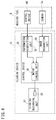
FIG. 4 is an overall configuration diagram of the cleaning device 10. The cleaning device 10 includes the above-mentioned cleaning mechanical unit 12 and a control device 30. The control device 30 is a computer including at least a processor such as a CPU and a memory. The control device 30 includes an information acquisition unit 32, an image recognition unit 34, and a motor control unit 36.
The information acquisition unit 32 acquires machining state information indicating a machining state of a machine tool M. The information acquisition unit 32 acquires the machining state information from a control device (for example, a numerical control device) NC of the machine tool M. As the machining state, there is included at least one of an ejection amount of a cutting fluid ejected in the machining area of the machine tool M, a spindle rotational speed of a spindle for rotating a tool, a cutting feed rate of the tool, and a cutting depth of the tool. Therefore, the machining state information acquired by the information acquisition unit 32 includes information indicating at least one of the ejection amount, the spindle rotational speed, the cutting feed rate, and the cutting depth. The information acquisition unit 32 outputs the acquired machining state information to the motor control unit 36.
There is a tendency that the larger the ejection amount is, the higher the spindle rotational speed is, the faster the cutting feed rate is, and the greater the cutting depth is, the more an amount of the adhering substance adhering to the lens cover 14 will increase. Therefore, the machining state information should include information helpful in estimating the amount of the adhering substance adhering to the lens cover 14.
The image recognition unit 34 acquires an image imaged by the camera Ca and recognizes the amount of the adhering substance that has adhered to the lens cover 14 based on the acquired image. The image recognition unit 34 can recognize an amount of the cutting fluid by recognizing the number of drops of the cutting fluid that have adhered to the lens cover 14, for example. Moreover, the image recognition unit 34 can recognize an amount of cutting chips depending on an area of the cutting chips that have adhered to the lens cover 14, for example. The image recognition unit 34 outputs the recognized amount of the adhering substance to the motor control unit 36.
The motor control unit 36 controls the rotational speed of the motor 20 (the rotational speed of the rotating shaft 20 a) based on at least one of the machining state information acquired by the information acquisition unit 32 and the amount of the adhering substance recognized by the image recognition unit 34. The motor control unit 36 may control the motor 20 such that the larger the ejection amount of the cutting fluid included in the machining state information acquired by the information acquisition unit 32 is, the higher the rotational speed of the motor 20 will be. The motor control unit 36 may control the motor 20 such that the higher the spindle rotational speed included in the machining state information acquired by the information acquisition unit 32 is, the higher the rotational speed of the motor 20 will be. The motor control unit 36 may control the motor 20 such that the faster the cutting feed rate included in the machining state information acquired by the information acquisition unit 32 is, the higher the rotational speed of the motor 20 will be. The motor control unit 36 may control the motor 20 such that the greater the cutting depth included in the machining state information acquired by the information acquisition unit 32 is, the higher the rotational speed of the motor 20 will be. Since the larger the ejection amount of the cutting fluid is, the higher the spindle rotational speed is, the faster the cutting feed rate is, and the greater the cutting depth is, the more easily the amount of the adhering substance adhering to the lens cover 14 will increase, then in these cases, the rotational speed of the motor 20 is increased.
Moreover, the motor control unit 36 may control the motor 20 such that the larger the amount of the adhering substance that has adhered to the lens cover 14 recognized by the image recognition unit 34 is, the higher the rotational speed of the motor 20 will be. The higher the rotational speed of the motor 20 is, the faster the adhering substance can be wiped, and the greater the amount of the adhering substance that can be wiped will be. Note that the rotational speed of the motor 20 never wastefully increases when the amount of the adhering substance adhering to the lens cover 14 is estimated (predicted) to be small, so electric power consumption can be suppressed.
MODIFIED EXAMPLES
The above-described embodiment may also be modified as follows.
Modified Example 1
It is possible that the information acquisition unit 32, prior to the machining state of the machine tool M changing, acquires the machining state information indicating the machining state after change. In this case, it is possible that the motor control unit 36, prior to the machining state of the machine tool M changing, antecedently changes the rotational speed of the motor 20 based on the machining state information after change.
Now, when the rotational speed of the motor 20 is changed, there occurs a time lag from control for changing the rotational speed of the motor 20 being performed by the motor control unit 36 to the rotational speed of the motor 20 actually changing. Occurrence of this time lag is caused by communication equipment interposing between the motor control unit 36 and the motor 20, inertia of the rotating shaft 20 a of the motor 20, rotation resistance due to friction, and so on. Therefore, if, in the case where the amount of the adhering substance adhering to the lens cover 14 will increase due to the machining state after change, control for changing the rotational speed of the motor 20 is performed after the machining state has changed, then sometimes removal of the adhering substance will be too late, and a clear and clean image will be unable to be photographed.
However, in present modified example 1, prior to the machining state of the machine tool M changing, the rotational speed of the motor 20 is antecedently changed based on the machining state information after change, so a difference (the time lag) between a timing when the machining state actually changes and a timing when the rotational speed of the motor 20 actually changes, can be reduced.
Modified Example 2
The machine tool M may be provided with a supply device for supplying compressed air or a cleaning fluid to at least one of the lens cover 14 and the wiping member 22. As a result, at least one of the lens cover 14 and the wiping member 22 can be cleaned by the compressed air or the cleaning fluid.
Modified Example 3
Although, in the above-described embodiment and modified examples 1 and 2, the case where there is one camera Ca has been described as an example, there may be a plurality of the cameras Ca. Providing a plurality of the cameras Ca makes it possible to, for example, generate a three-dimensional image from a plurality of images obtained.
FIG. 5 is a view for describing a cleaning mechanical unit 12 in modified example 3. Note that configurations similar to in the above-described embodiment will be assigned with the same reference symbols as in the above-described embodiment, and only differing portions will be described. Note that in FIG. 5, the number of cameras Ca is assumed to be two, and that, sometimes, one of the cameras Ca will be called Ca1 and the other of the cameras Ca will be called Ca2.
As shown in FIG. 5, the lens cover 14 covers the object lenses Cl of two cameras Ca (Ca1, Ca2). In other words, the lens cover 14 is disposed so as to face the object lenses Cl of the two cameras Ca (Ca1, Ca2). The motor 20 and the two cameras Ca (Ca1, Ca2) are provided in the space 21 formed by the lens cover 14 and the housing 16.
Moreover, two of the wiping members 22 are also provided correspondingly to the two cameras Ca (Ca1, Ca2). Now, in some cases, the wiping member 22 corresponding to the camera Ca1 will be called 22 a, and the wiping member 22 corresponding to the camera Ca2 will be called 22 b. As described in the above-described embodiment, these two wiping members 22 (22 a, 22 b) may each have a shape that is crooked in an opposite direction to the rotational direction of the lens cover 14 (i.e., bent toward the rotational direction).
Moreover, the camera Ca1 and the wiping member 22 a may be disposed such that when viewed from a side facing the object lens Cl, a distance between the object lens Cl of the camera Ca1 and the wiping member 22 a is a certain distance or less, and the object lens Cl of the camera Ca1 is positioned on a rotational direction side of the wiping member 22 a. Similarly, the camera Ca2 and the wiping member 22 b may be disposed such that when viewed from a side facing the object lens Cl, a distance between the object lens Cl of the camera Ca2 and the wiping member 22 b is a certain distance or less, and the object lens Cl of the camera Ca2 is positioned on a rotational direction side of the wiping member 22 b.
As shown in FIG. 5, when the two cameras Ca1, Ca2 are provided so as to image an object-to-be-photographed along a direction intersecting the gravity direction, at least one of the wiping members 22 may be provided more downwardly (more in a gravity acting direction) than the central position of the lens cover 14. Moreover, the two wiping members 22 (22 a, 22 b) may be integrally formed.
Modified Example 4
Although in the above-described embodiment and modified examples 1 to 3, the number of cameras Ca and the number of wiping members 22 were made the same, the number of wiping members 22 may be larger than the number of cameras Ca.
Modified Example 5
In the above-described embodiment and modified examples 1 to 4, one cleaning device 10 (cleaning mechanical unit 12 and control device 30) was provided correspondingly to one machine tool M. In the present modified example 5, as shown in FIG. 6, multiple cleaning mechanical units 12 may be provided respectively to a plurality of the machine tools M, and the control device 30 may control the plurality of cleaning mechanical units 12. In this case, it results in the cleaning device 10 being configured by the plurality of cleaning mechanical units 12 and the control device 30.
The control device 30 may change the rotational speed of the motor 20 for each of the machine tools M. In other words, since the amount of the adhering substance adhering to the lens cover 14 of the cleaning mechanical unit 12 will sometimes differ for each of the machine tools M, the rotational speed of the motor 20 may be changed for each of the machine tools M depending on the amount of the adhering substance. This amount of the adhering substance can be estimated based on the machining state information sent from the control device NC of the machine tool M and the image sent from the camera Ca provided correspondingly to the machine tool M.
Modified Example 6
Although in the above-described embodiment and modified examples 1 to 4, the control device 30 of the cleaning device 10 was provided separately from the control device NC of the machine tool M, the control device 30 of the cleaning device 10 may be the control device NC of the machine tool M.
Technical Ideas Obtained from Embodiment
Technical ideas understandable from the above-described embodiment and modified examples 1 to 6 will be described below.
The cleaning device (10) includes: a lens cover (14) configured to cover an object lens (Cl) of a camera (Ca) provided in a machining area of a machine tool (M), the lens cover being transparent; a motor (20) configured to rotate the lens cover (14); and a wiping member (22) configured to, when the lens cover (14) rotates, wipe at least an adhering substance that has adhered to a region of the lens cover (14) in an angle-of-view of the camera (Ca).
As a result, at least the adhering substance that has adhered to the region of the lens cover (14) in the angle-of-view of the camera (Ca) can be removed, so a clear and clean image can be obtained.
The cleaning device (10) may further include: a housing (16) including an opening section (14 a) and configured to house the camera (Ca) and the motor (20); a seal member (18) provided between the housing (16) and the lens cover (14) covering the opening section (14 a); and a bracket (24) configured to fix the wiping member (22) to the housing (16), the wiping member being provided on an opposite side to a housing (16) side of the lens cover (14). As a result, the camera (Ca) and the motor (20) can be protected from the adhering substance, and the adhering substance can be prevented from adhering to a surface of the lens cover (14) on a camera (Ca) side.
The cleaning device (10) may further include: an information acquisition unit (32) configured to acquire machining state information indicating a machining state of the machine tool (M); and a motor control unit (36) configured to control a rotational speed of the motor (20) based on the machining state information acquired by the information acquisition unit (32). The machining state may include at least one of an ejection amount of a cutting fluid ejected in the machining area, a spindle rotational speed of a spindle for rotating a tool, a cutting feed rate of the tool, and a cutting depth of the tool. As a result, even when an amount of the adhering substance adhering to the lens cover (14) increases, a larger amount of the adhering substance can be quickly removed, and a clear and clean image can be obtained. Moreover, when the amount of the adhering substance decreases, the rotational speed of the motor (20) never wastefully increases, so electric power consumption can be suppressed.
In the cleaning device, the information acquisition unit (32), prior to the machining state of the machine tool (M) changing, may acquire the machining state information indicating the machining state after change, and the motor control unit (36), prior to the machining state of the machine tool (M) changing, may antecedently change the rotational speed of the motor (20) based on the machining state information after change. As a result, a difference (a time lag) between a timing when the machining state actually changes and a timing when the rotational speed of the motor (20) actually changes, can be reduced.
The cleaning device (10) may further include: an image recognition unit (34) configured to acquire an image imaged by the camera (Ca) and thereby recognize an amount of the adhering substance that has adhered to the lens cover (14); and a motor control unit (36) configured to control a rotational speed of the motor (20) based on the amount of the adhering substance recognized by the image recognition unit (34). As a result, even when an amount of the adhering substance adhering to the lens cover (14) increases, a larger amount of the adhering substance can be quickly removed, and a clear and clean image can be obtained. Moreover, when the amount of the adhering substance decreases, the rotational speed of the motor (20) is never wastefully increased, so electric power consumption can be suppressed.
While the invention has been particularly shown and described with reference to the preferred embodiments, it will be understood that variations and modifications can be effected thereto by those skilled in the art without departing from the scope of the invention as defined by the appended claims.

Claims (4)

What is claimed is:
1. A cleaning device comprising:
a lens cover configured to cover an object lens of a camera provided in a machining area of a machine tool, the lens cover being transparent;
a motor configured to rotate the lens cover; and
a wiping member configured to, when the lens cover rotates, wipe at least an adhering substance that has adhered to a region of the lens cover in an angle-of-view of the camera,
an information acquisition unit configured to acquire machining state information indicating a machining state of the machine tool; and
a motor control unit configured to control a rotational speed of the motor based on the machining state information acquired by the information acquisition unit,
wherein the machining state includes at least one of an ejection amount of a cutting fluid ejected in the machining area, a spindle rotational speed of a spindle for rotating a tool, a cutting feed rate of the tool, and a cutting depth of the tool.
2. The cleaning device according to claim 1, further comprising:
a housing including an opening section and configured to house the camera and the motor;
a seal member provided between the housing and the lens cover covering the opening section; and
a bracket configured to fix the wiping member to the housing, the wiping member being provided on an opposite side to a housing side of the lens cover.
3. The cleaning device according to claim 1, wherein
the information acquisition unit, prior to the machining state of the machine tool changing, acquires the machining state information indicating the machining state after change, and
the motor control unit, prior to the machining state of the machine tool changing, antecedently changes the rotational speed of the motor based on the machining state information after change.
4. The cleaning device according to claim 1, further comprising:
an image recognition unit configured to acquire an image imaged by the camera and thereby recognize an amount of the adhering substance that has adhered to the lens cover,
wherein the motor control unit is configured to control the rotational speed of the motor based on the machining state information acquired by the information acquisition unit and the amount of the adhering substance recognized by the image recognition unit.
US16/373,932 2018-04-04 2019-04-03 Cleaning device Expired - Fee Related US10866411B2 (en)

Applications Claiming Priority (2)

Application Number Priority Date Filing Date Title
JP2018-072047 2018-04-04
JP2018072047A JP6740275B2 (en) 2018-04-04 2018-04-04 Cleaning device

Publications (2)

Publication Number Publication Date
US20190310471A1 US20190310471A1 (en) 2019-10-10
US10866411B2 true US10866411B2 (en) 2020-12-15

Family

ID=67991535

Family Applications (1)

Application Number Title Priority Date Filing Date
US16/373,932 Expired - Fee Related US10866411B2 (en) 2018-04-04 2019-04-03 Cleaning device

Country Status (4)

Country Link
US (1) US10866411B2 (en)
JP (1) JP6740275B2 (en)
CN (2) CN110340718B (en)
DE (1) DE102019002406B4 (en)

Cited By (1)

* Cited by examiner, † Cited by third party
Publication number Priority date Publication date Assignee Title
TWI800433B (en) * 2022-07-28 2023-04-21 劉哲安 Embedded camera unit with self-cleaning function

Families Citing this family (11)

* Cited by examiner, † Cited by third party
Publication number Priority date Publication date Assignee Title
JP6740275B2 (en) * 2018-04-04 2020-08-12 ファナック株式会社 Cleaning device
US12269437B2 (en) * 2019-12-10 2025-04-08 Nuro, Inc Sensor cleaning mechanism for an autonomous vehicle
CN111147814B (en) * 2019-12-10 2021-05-11 陕西铭泊停车服务有限公司 Monitoring device with protection function for parking lot
CN111011050B (en) * 2019-12-31 2022-02-22 江苏翰雅有机农场有限公司 Cultivate household utensils cleaning device
KR102124996B1 (en) * 2020-02-17 2020-06-19 (주)유한프리젠 Camera lens automatic cleaning device
KR20220055618A (en) 2020-10-27 2022-05-04 한화디펜스 주식회사 Apparatus for cleaning sensors
CN112738369A (en) * 2020-12-24 2021-04-30 丽水市卓纳建筑设计有限公司 Artificial intelligence system
CN113976503B (en) * 2021-12-03 2023-03-14 沧州职业技术学院 Bioengineering image analysis input device
CN115199858B (en) * 2022-06-23 2023-07-21 武汉盛永智杰科技有限公司 Metal pipe section detection equipment
CN115379103B (en) * 2022-10-25 2022-12-20 合肥岭雁科技有限公司 Security monitoring camera
CN116045733B (en) * 2022-12-22 2024-11-26 江苏缪斯光电科技有限公司 A high-precision sight with a reflective optical system

Citations (13)

* Cited by examiner, † Cited by third party
Publication number Priority date Publication date Assignee Title
US20020002885A1 (en) * 2000-04-25 2002-01-10 Ilmar Luik Combined video camera and toolholder
JP2002018680A (en) 2000-07-10 2002-01-22 Mitsubishi Electric Corp Machine Tools
US6358115B1 (en) * 1998-12-09 2002-03-19 Taiyo Yuden Co. Ltd. Dicing apparatus
US20020139394A1 (en) * 2001-04-03 2002-10-03 Barry Bronson Self-cleaning lens shield
JP2007110665A (en) 2005-10-13 2007-04-26 For-A Co Ltd Camera housing device
JP2008288720A (en) 2007-05-15 2008-11-27 Hitachi Information & Communication Engineering Ltd Cleaning apparatus of camera dome
JP2010158726A (en) 2009-01-06 2010-07-22 Mitsubishi Heavy Ind Ltd Tooling washing device for machine tool
US20110181725A1 (en) * 2010-01-27 2011-07-28 Nippon Soken, Inc. Optical sensor device for vehicle
JP2015182656A (en) * 2014-03-25 2015-10-22 三菱自動車工業株式会社 Lens cover cleaning device of electronic mirror
JP2017076933A (en) 2015-10-16 2017-04-20 株式会社東京アールアンドデー Wiper device for optical equipment
US20170192226A1 (en) * 2012-07-02 2017-07-06 Agricam Ab Self-cleaning camera housings, self-cleaning camera modules, and monitoring systems comprising self-cleaning camera modules
JP2017119480A (en) 2015-12-28 2017-07-06 富士通テン株式会社 Deposit removal device
JP2017165287A (en) 2016-03-16 2017-09-21 三菱自動車工業株式会社 Water drop remover for in-vehicle imaging device

Family Cites Families (6)

* Cited by examiner, † Cited by third party
Publication number Priority date Publication date Assignee Title
DE10360283B3 (en) 2003-12-20 2005-04-14 Piller Entgrattechnik Gmbh Viewing device for object contained in dust- and moisture-laden environment using transparent disc rotated past radial wiper blade for removal of deposited dust and moisture
US9774768B1 (en) * 2016-05-31 2017-09-26 GM Global Technology Operations LLC Wipeable camera system and device
CN205996976U (en) * 2016-09-09 2017-03-08 常州信息职业技术学院 A kind of wireless environment parameter sampling robot control system
CN206533442U (en) * 2017-01-28 2017-09-29 青岛福鼎数码科技有限公司 Can automatic cleaning type monitoring camera in real time
CN207010813U (en) * 2017-08-10 2018-02-13 杭州敏坤电子科技有限公司 A kind of automatic cleaning type high-definition camera component
JP6740275B2 (en) * 2018-04-04 2020-08-12 ファナック株式会社 Cleaning device

Patent Citations (16)

* Cited by examiner, † Cited by third party
Publication number Priority date Publication date Assignee Title
US6358115B1 (en) * 1998-12-09 2002-03-19 Taiyo Yuden Co. Ltd. Dicing apparatus
US20020002885A1 (en) * 2000-04-25 2002-01-10 Ilmar Luik Combined video camera and toolholder
JP2002018680A (en) 2000-07-10 2002-01-22 Mitsubishi Electric Corp Machine Tools
US20020139394A1 (en) * 2001-04-03 2002-10-03 Barry Bronson Self-cleaning lens shield
JP2007110665A (en) 2005-10-13 2007-04-26 For-A Co Ltd Camera housing device
JP2008288720A (en) 2007-05-15 2008-11-27 Hitachi Information & Communication Engineering Ltd Cleaning apparatus of camera dome
JP2010158726A (en) 2009-01-06 2010-07-22 Mitsubishi Heavy Ind Ltd Tooling washing device for machine tool
US20110265835A1 (en) * 2009-01-06 2011-11-03 Mitsubishi Heavy Industries, Ltd. Tool cleaning device for machine tool
JP2011155468A (en) 2010-01-27 2011-08-11 Nippon Soken Inc Optical sensor device for vehicle
US20110181725A1 (en) * 2010-01-27 2011-07-28 Nippon Soken, Inc. Optical sensor device for vehicle
US20170192226A1 (en) * 2012-07-02 2017-07-06 Agricam Ab Self-cleaning camera housings, self-cleaning camera modules, and monitoring systems comprising self-cleaning camera modules
JP2015182656A (en) * 2014-03-25 2015-10-22 三菱自動車工業株式会社 Lens cover cleaning device of electronic mirror
JP2017076933A (en) 2015-10-16 2017-04-20 株式会社東京アールアンドデー Wiper device for optical equipment
JP2017119480A (en) 2015-12-28 2017-07-06 富士通テン株式会社 Deposit removal device
US20180246322A1 (en) * 2015-12-28 2018-08-30 Fujitsu Ten Limited Extraneous-matter removing apparatus
JP2017165287A (en) 2016-03-16 2017-09-21 三菱自動車工業株式会社 Water drop remover for in-vehicle imaging device

Non-Patent Citations (13)

* Cited by examiner, † Cited by third party
Title
English Abstract and Machine Translation for Japanese Publication No. 2015-182656 A, published Oct. 22, 2015, 11 pgs.
English Abstract and Machine Translation for Japanese Publication No. 2017-076933 A, published Apr. 20, 2017, 8 pgs.
English Abstract and Machine Translation for Japanese Publication No. 2017-165287 A, published Sep. 21, 2017, 7 pgs.
English Abstract and Machine Translation for Japanese Publication No. JP2002-018680A, published Jan. 22, 2002, 17 pgs.
English Abstract and Machine Translation for Japanese Publication No. JP2007-110665A, published Apr. 26, 2007, 11 pgs.
English Abstract and Machine Translation for Japanese Publication No. JP2008-288720A, published Nov. 27, 2008, 10 pgs.
English Abstract for Japanese Publication No. 2010158726 A, published Jul. 22, 2010, 1 pg.
English Abstract for Japanese Publication No. 2011155468 A, published Aug. 11, 2011, 2 pgs.
English Abstract for Japanese Publication No. 2017119480 A, published Jul. 6, 2017, 1 pg.
English Machine Translation of Decision to Grant a Patent mailed by Japan Patent Office (JPO) for Application No. JP2018-072047, dated Jun. 23, 2020, 2 pages.
English Machine Translation of Notification of Reasons for Refusal mailed by Japan Patent Office (JPO) for Application No. JP2018-072047, dated Apr. 7, 2020, 4 pages.
Untranslated Decision to Grant a Patent mailed by Japan Patent Office (JPO) for Application No. JP2018-072047, dated Jun. 23, 2020, 3 pages.
Untranslated Notification of Reasons for Refusal mailed by Japan Patent Office (JPO) for Application No. JP2018-072047, dated Apr. 7, 2020, 4 pages.

Cited By (1)

* Cited by examiner, † Cited by third party
Publication number Priority date Publication date Assignee Title
TWI800433B (en) * 2022-07-28 2023-04-21 劉哲安 Embedded camera unit with self-cleaning function

Also Published As

Publication number Publication date
CN110340718B (en) 2021-06-01
JP6740275B2 (en) 2020-08-12
JP2019186632A (en) 2019-10-24
US20190310471A1 (en) 2019-10-10
DE102019002406B4 (en) 2024-08-14
CN110340718A (en) 2019-10-18
CN209919429U (en) 2020-01-10
DE102019002406A1 (en) 2019-10-10

Similar Documents

Publication Publication Date Title
US10866411B2 (en) Cleaning device
US10843668B2 (en) Device for protecting an optical sensor, and associated driver assistance system and cleaning method
US10859818B2 (en) Cleaning system for a camera lens
US9348196B1 (en) System including a seamless lens cover and related methods
JP6412185B2 (en) Machine tool system
US11079592B2 (en) Device for protecting an optical sensor and driving aid system comprising an optical sensor
KR102124996B1 (en) Camera lens automatic cleaning device
US10969478B2 (en) Vehicle object-detection sensor system
US20220234545A1 (en) Rotating blade mechanism for cleaning cylindrical sensors
US10730449B2 (en) Device for protecting an optical sensor, driving assistance system and corresponding assembly method
US20160304029A1 (en) Vehicle camera enclosure
JP2019131097A (en) Vehicle shooting device
US11285921B2 (en) Device for protecting an optical sensor of a driving assistance system for a motor vehicle
US20080181600A1 (en) Photographing Device in Particular For Video Surveillance and Working Methods of Same
KR20230019255A (en) Security camera system
JP6649984B2 (en) Viewing window dirt remover
CN204928999U (en) Camera device and install camera device's car
CN112958494A (en) Vehicle-mounted vision acquisition module, active cleaning device thereof and unmanned vehicle
US20240012315A1 (en) Mount and camera system
CN217484678U (en) Camera module with droplet removal device
CN214070013U (en) Vehicle-mounted vision acquisition module, active cleaning device thereof and unmanned vehicle
KR20240137867A (en) Cleaning System for of Sensor Unit
US11022862B2 (en) Imaging system
JP6638147B2 (en) Imaging system and moving object
CN211014897U (en) Glasses with three cameras

Legal Events

Date Code Title Description
AS Assignment

Owner name: FANUC CORPORATION, JAPAN

Free format text: ASSIGNMENT OF ASSIGNORS INTEREST;ASSIGNORS:ADACHI, HIDEAKI;KUROSUMI, YASUHIKO;TARUI, YOSHIHIKO;REEL/FRAME:048781/0428

Effective date: 20190315

FEPP Fee payment procedure

Free format text: ENTITY STATUS SET TO UNDISCOUNTED (ORIGINAL EVENT CODE: BIG.); ENTITY STATUS OF PATENT OWNER: LARGE ENTITY

STPP Information on status: patent application and granting procedure in general

Free format text: DOCKETED NEW CASE - READY FOR EXAMINATION

STPP Information on status: patent application and granting procedure in general

Free format text: PUBLICATIONS -- ISSUE FEE PAYMENT RECEIVED

STPP Information on status: patent application and granting procedure in general

Free format text: PUBLICATIONS -- ISSUE FEE PAYMENT VERIFIED

STCF Information on status: patent grant

Free format text: PATENTED CASE

FEPP Fee payment procedure

Free format text: MAINTENANCE FEE REMINDER MAILED (ORIGINAL EVENT CODE: REM.); ENTITY STATUS OF PATENT OWNER: LARGE ENTITY

LAPS Lapse for failure to pay maintenance fees

Free format text: PATENT EXPIRED FOR FAILURE TO PAY MAINTENANCE FEES (ORIGINAL EVENT CODE: EXP.); ENTITY STATUS OF PATENT OWNER: LARGE ENTITY

STCH Information on status: patent discontinuation

Free format text: PATENT EXPIRED DUE TO NONPAYMENT OF MAINTENANCE FEES UNDER 37 CFR 1.362

FP Lapsed due to failure to pay maintenance fee

Effective date: 20241215