US10862759B2 - Communication network determination apparatus, communication network determination method, and recording medium having communication network determination program recorded therein - Google Patents
Communication network determination apparatus, communication network determination method, and recording medium having communication network determination program recorded therein Download PDFInfo
- Publication number
- US10862759B2 US10862759B2 US16/312,428 US201716312428A US10862759B2 US 10862759 B2 US10862759 B2 US 10862759B2 US 201716312428 A US201716312428 A US 201716312428A US 10862759 B2 US10862759 B2 US 10862759B2
- Authority
- US
- United States
- Prior art keywords
- communication network
- communication
- information processing
- processing apparatus
- identifier
- Prior art date
- Legal status (The legal status is an assumption and is not a legal conclusion. Google has not performed a legal analysis and makes no representation as to the accuracy of the status listed.)
- Active, expires
Links
Images


Classifications
-
- H—ELECTRICITY
- H04—ELECTRIC COMMUNICATION TECHNIQUE
- H04L—TRANSMISSION OF DIGITAL INFORMATION, e.g. TELEGRAPHIC COMMUNICATION
- H04L41/00—Arrangements for maintenance, administration or management of data switching networks, e.g. of packet switching networks
- H04L41/08—Configuration management of networks or network elements
- H04L41/085—Retrieval of network configuration; Tracking network configuration history
- H04L41/0853—Retrieval of network configuration; Tracking network configuration history by actively collecting configuration information or by backing up configuration information
-
- H—ELECTRICITY
- H04—ELECTRIC COMMUNICATION TECHNIQUE
- H04L—TRANSMISSION OF DIGITAL INFORMATION, e.g. TELEGRAPHIC COMMUNICATION
- H04L41/00—Arrangements for maintenance, administration or management of data switching networks, e.g. of packet switching networks
- H04L41/12—Discovery or management of network topologies
-
- H—ELECTRICITY
- H04—ELECTRIC COMMUNICATION TECHNIQUE
- H04L—TRANSMISSION OF DIGITAL INFORMATION, e.g. TELEGRAPHIC COMMUNICATION
- H04L41/00—Arrangements for maintenance, administration or management of data switching networks, e.g. of packet switching networks
- H04L41/06—Management of faults, events, alarms or notifications
- H04L41/0631—Management of faults, events, alarms or notifications using root cause analysis; using analysis of correlation between notifications, alarms or events based on decision criteria, e.g. hierarchy, tree or time analysis
- H04L41/0636—Management of faults, events, alarms or notifications using root cause analysis; using analysis of correlation between notifications, alarms or events based on decision criteria, e.g. hierarchy, tree or time analysis based on a decision tree analysis
-
- H—ELECTRICITY
- H04—ELECTRIC COMMUNICATION TECHNIQUE
- H04L—TRANSMISSION OF DIGITAL INFORMATION, e.g. TELEGRAPHIC COMMUNICATION
- H04L41/00—Arrangements for maintenance, administration or management of data switching networks, e.g. of packet switching networks
- H04L41/06—Management of faults, events, alarms or notifications
- H04L41/0677—Localisation of faults
-
- H—ELECTRICITY
- H04—ELECTRIC COMMUNICATION TECHNIQUE
- H04L—TRANSMISSION OF DIGITAL INFORMATION, e.g. TELEGRAPHIC COMMUNICATION
- H04L43/00—Arrangements for monitoring or testing data switching networks
- H04L43/08—Monitoring or testing based on specific metrics, e.g. QoS, energy consumption or environmental parameters
- H04L43/0823—Errors, e.g. transmission errors
-
- H—ELECTRICITY
- H04—ELECTRIC COMMUNICATION TECHNIQUE
- H04L—TRANSMISSION OF DIGITAL INFORMATION, e.g. TELEGRAPHIC COMMUNICATION
- H04L43/00—Arrangements for monitoring or testing data switching networks
- H04L43/12—Network monitoring probes
-
- H—ELECTRICITY
- H04—ELECTRIC COMMUNICATION TECHNIQUE
- H04L—TRANSMISSION OF DIGITAL INFORMATION, e.g. TELEGRAPHIC COMMUNICATION
- H04L43/00—Arrangements for monitoring or testing data switching networks
- H04L43/04—Processing captured monitoring data, e.g. for logfile generation
- H04L43/045—Processing captured monitoring data, e.g. for logfile generation for graphical visualisation of monitoring data
Definitions
- the present invention relates to a communication network determination apparatus and the like that determine a state of a communication network.
- the fault detection apparatus includes a trap acquisition unit, a configuration acquisition unit, a configuration prediction unit, and a fault probability table management unit.
- the trap acquisition unit acquires notification information indicating that a configuration of a communication network has changed.
- the configuration acquisition unit acquires, based on the notification information and the configuration of the communication network, a configuration of a communication network after the change.
- the configuration prediction unit determines a prediction configuration based on a redundancy configuration relating to the configuration. The redundancy configuration has been acquired from equipment included in the communication network.
- the fault probability table management unit estimates a fault point where a fault has occurred in the communication network based on a fault occurrence notification indicating a content of a fault, the configuration information, and a fault probability table indicating a probability of a cause point with respect to each content of the fault.
- PTL 2 discloses a monitor apparatus that monitors facility equipment and information processing equipment in an energy management system.
- the monitor apparatus communicably connects to an energy system including information processing equipment, facility equipment, and a control apparatus that controls the facility equipment.
- the monitor apparatus acquires path information indicating a path in a first communication network to which the information processing equipment and the control apparatus connect.
- the monitor apparatus acquires path information indicating a path in a second communication network to which the facility equipment and the control apparatus connect.
- the first communication network is different from the second communication network in communication method.
- the monitor apparatus specifies, based on two pieces of path information, a connection relation among the information processing equipment, the facility equipment, and the control apparatus and outputs display information indicating the identified relation.
- One of objectives of the present invention is to provide a communication network determination apparatus and the like capable of accurately specifying a communication network monitorable by a monitor apparatus even when it is difficult to necessarily and sufficiently acquire configuration information relating to a configuration of a communication network.
- a communication network determination apparatus including:
- calculation means for calculating a number of types of communication identifier associated with an apparatus identifier of a second information apparatus in monitoring information where a communication identifier allocated to a first information apparatus in a second communication network and an apparatus identifier of a second information apparatus that relays a communication in a first communication network, the monitoring information generated based on communication network via the first communication network;
- determination means for determining that the first communication network is the same as the second communication network when the calculated number of types is one, and determining that the first communication network is different from the second communication network when the calculated number of types is two or more.
- a communication network determination method including:
- the first communication network is the same as the second communication network when the calculated number of types is one, and determining that the first communication network is different from the second communication network when the calculated number of types is two or more.
- a communication network determination program makes a computer achieve:
- a calculation function for calculating a number of types of communication identifier associated with an apparatus identifier of a second information apparatus in monitoring information where a communication identifier allocated to a first information apparatus in a second communication network and an apparatus identifier of a second information apparatus that relays a communication in a first communication network, the monitoring information generated based on communication network via the first communication network;
- a determination function for determining that the first communication network is the same as the second communication network when the calculated number of types is one, and determining that the first communication network is different from the second communication network when the calculated number of types is two or more.
- the object is also achieved by a computer-readable recording medium that records the program.
- a communication network monitorable by a monitor apparatus can be accurately specified even when it is difficult to necessarily and sufficiently acquire configuration information relating to a configuration of a communication network.
- FIG. 1 is a block diagram illustrating a configuration of a communication network determination apparatus according to a first example embodiment of the present invention.
- FIG. 2 is a flowchart illustrating a processing flow in the communication network determination apparatus according to the first example embodiment.
- FIG. 3 is a diagram conceptually illustrating an example of monitoring information stored in a monitoring information storage unit.
- FIG. 4 is a block diagram illustrating a configuration of a communication network determination apparatus according to a second example embodiment of the present invention.
- FIG. 5 is a flowchart illustrating a processing flow in the communication network determination apparatus according to the second example embodiment.
- FIG. 6 is a diagram conceptually illustrating an example of monitoring information stored in a monitoring information storage unit.
- FIG. 7 is a block diagram illustrating a configuration of a communication network determination apparatus according to a third example embodiment of the present invention.
- FIG. 8 is a flowchart illustrating a processing flow in the communication network determination apparatus according to the third example embodiment.
- FIG. 9 is a block diagram illustrating a configuration of a communication network determination apparatus according to a fourth example embodiment of the present invention.
- FIG. 10 is a flowchart illustrating a processing flow in the communication network determination apparatus according to the fourth example embodiment.
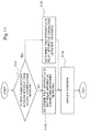
- FIG. 11 is a flowchart illustrating a processing flow in the communication network determination apparatus according to the fourth example embodiment.
- FIG. 12 is a diagram conceptually illustrating an example of function information stored in a function information storage unit.
- FIG. 13 is a diagram conceptually illustrating an example of display information.
- FIG. 14 is a diagram illustrating an example of a user interface.
- FIG. 15 is a diagram illustrating an example of a user interface.
- FIG. 16 is a block diagram schematically illustrating a hardware configuration of a calculation processing apparatus capable of achieving communication network determination apparatus according to each example embodiments of the present invention.
- FIG. 1 is a block diagram illustrating a configuration of the communication network determination apparatus 101 according to the first example embodiment of the present invention.
- the communication network determination apparatus 101 includes a calculation unit (calculator) 102 and a determination unit (determiner) 103 .
- the communication network determination apparatus 101 can refer to a monitoring information storage unit 201 that stores monitoring information (to be described later with reference to FIG. 3 ).
- a monitor apparatus 207 reads communication information (communication data) communicated through a first communication network 208 and reads, from the read communication information, an apparatus ID capable of identifying an information processing apparatus having relayed the communication, a communication ID allocated to an information processing apparatus 211 having communicated the information, and the like. It is assumed that the monitor apparatus 207 generates monitoring information (to be described later with reference to FIG. 3 ) in which the read apparatus ID, the read communication ID, and the like are associated with one another and stores the generated monitoring information in the monitoring information storage unit 201 .
- FIG. 3 is a diagram conceptually illustrating an example of monitoring information stored in the monitoring information storage unit 201 .
- Monitoring information associates the following items 1 to 3 with one another with regard to a communication performed through the first communication network 208 .
- these items are
- Monitoring information may further include content information indicating processing relating to performed communication.
- the information processing apparatus 211 and the relay apparatus 209 may be one information processing apparatus or may be separated information processing apparatuses.
- a time “11:12:13”, a communication ID “192.168.7.5”, and an apparatus ID “44:55:66:77:88:99” are associated with one another.
- the monitor apparatus 207 detects that a communication has been performed at a time “11:12:13”.
- a communication ID allocated to the information processing apparatus 211 in the second communication network 210 is “192.168.7.5”.
- an apparatus ID of the relay apparatus 209 is “44:55:66:77:88:99”.
- Communication information may not necessarily include the above-described items.
- the above-described apparatus ID is described in a hexadecimal number.
- the monitor apparatus 207 reads an apparatus ID and a communication ID from communication information (communication data) communicated through the first communication network 208 , generates monitoring information (exemplified in FIG. 3 ) in which the read apparatus ID and communication ID are associated with each other, and stores the generated monitoring information in the monitoring information storage unit 201 .
- the monitor apparatus 207 may generate monitoring information in which the apparatus ID is further associated with a time at which the communication has been detected.
- FIG. 2 is a flowchart illustrating a processing flow in the communication network determination apparatus 101 according to the first example embodiment.
- the monitoring information storage unit 201 stores monitoring information as described with reference to FIG. 3 .
- the communication network determination apparatus 101 may receive monitoring information generated by the monitor apparatus 207 monitoring the first communication network 208 .
- the calculation unit 102 reads monitoring information stored in the monitoring information storage unit 201 .
- the calculation unit 102 may read all monitoring information stored in the monitoring information storage unit 201 or may read monitoring information generated during a predetermined period.
- the calculation unit 102 reads a communication ID relating to a certain communication and an apparatus ID relating to the communication from the read monitoring information (exemplified in FIG. 3 ).
- the calculation unit 102 calculates the number of types of communication IDs associated with the read apparatus ID (step S 101 ).
- the determination unit 103 determines whether or not the number of types calculated by the calculation unit 102 is equal to or more than 2 (step S 102 ).
- the determination unit 103 determines that the first communication network 208 and the second communication network 210 are the same (step S 103 ).
- the first communication network 208 communicably connects to the monitor apparatus 207 .
- the second communication network 210 communicably connects to the information processing apparatus 211 identified by a communication ID.
- the determination unit 103 determines that the monitor apparatus 207 monitoring communication in the first communication network 208 and the information processing apparatus 211 having performed a communication in the second communication network 210 communicably connect to the same communication network.
- the determination unit 103 determines that the first communication network 208 and the second communication network 210 are different from each other (step S 104 ).
- the first communication network 208 communicably connects to the monitor apparatus 207 .
- the second communication network 210 communicably connects to the information processing apparatus 211 identified by a communication ID.
- the determination unit 103 determines that the monitor apparatus 207 monitoring communication in the first communication network 208 and the information processing apparatus 211 having performed a communication in the second communication network 210 communicably connect to different communication networks.
- the processing illustrated in FIG. 2 may be executed for all apparatus IDs included in monitoring information (exemplified in FIG. 3 ) stored in the monitoring information storage unit 201 .
- the communication network determination apparatus 101 can accurately specify a communication network monitorable by the monitor apparatus 207 even when it is difficult to necessarily and sufficiently acquire configuration information relating to a configuration of a communication network.
- the reason is that the communication network determination apparatus 101 determines whether or not the monitor apparatus 207 monitoring the first communication network 208 and the information processing apparatus 211 having performed a communication through the communication network communicably connect to the same communication network. The reason will be described in more detail.
- the monitor apparatus when a monitor apparatus and an information processing apparatus communicably connect to a common communication network, the monitor apparatus can monitor an information processing apparatus through the communication network.
- the monitor apparatus when a monitor apparatus and an information processing apparatus communicably connect to different communication networks, the monitor apparatus has a difficulty of monitoring an information processing apparatus through the communication network.
- the information processing apparatus 211 communicates communication information through the relay apparatus 209 (e.g. a gateway) and the first communication network 208 .
- the relay apparatus 209 is configured to perform the relaying between the first communication network 208 and the second communication network 210 .
- Monitoring information (exemplified in FIG. 3 ) generated by the monitor apparatus 207 includes an apparatus ID of the relay apparatus 209 and a communication ID allocated, in the second communication network 210 , to the information processing apparatus 211 .
- the monitor apparatus 207 when a plurality of information processing apparatuses 211 communicably connect to the second communication network 210 , the monitor apparatus 207 generates monitoring information in which an apparatus ID of the relay apparatus 209 with a communication ID allocated, in the second communication network 210 , to each information processing apparatus are associated with each other. Therefore, in this case, the monitoring information generated during a given period associates an apparatus ID of the relay apparatus 209 with a plurality of types of communication IDs.
- the communication network determination apparatus 101 determines, when one apparatus ID is associated with a plurality of types of communication IDs, that the first communication network 208 communicably connecting to the monitor apparatus 207 and the second communication network 210 where each communication ID is allocated are different from each other.
- the relay apparatus 209 and the information processing apparatus 211 indicate one information processing apparatus.
- the monitoring information monitored during a given period associates an apparatus ID capable of identifying the relay apparatus 209 (in this case, the information processing apparatus 211 ) with one type of a communication ID (i.e. one communication ID allocated to the information processing apparatus 211 ). Therefore, in this case, the monitoring information monitored during a given period associates an apparatus ID indicating the relay apparatus 209 with one communication ID.
- the communication network determination apparatus 101 determines, when one apparatus ID is associated with one communication ID, that the first communication network communicably connecting to the monitor apparatus 207 and the second communication network 210 communicably connecting to the information processing apparatus 211 are the same.
- the communication network determination apparatus 101 can specify a communication network monitorable by the monitor apparatus 207 .
- FIG. 4 is a block diagram illustrating a configuration of the communication network determination apparatus 111 according to the second example embodiment of the present invention.
- the communication network determination apparatus 111 includes a calculation unit (calculator) 102 and a determination unit (determiner) 113 .
- the communication network determination apparatus 111 can refer to a monitoring information storage unit 202 configured to store monitoring information (to be described later with reference to FIG. 6 ).
- a monitor apparatus 207 reads communication information (communication data) communicated through a first communication network 208 and reads, from the read communication information, an apparatus ID of an information processing apparatus (represented as a “relay apparatus 209 ” in this case) having relayed the communication, a communication ID allocated to an information processing apparatus 211 , content information indicating processing executed in the communication, and the like.
- the monitor apparatus 207 generates monitoring information (to be described later with reference to FIG. 6 ) in which the read apparatus ID, the read communication ID, and the like are associated with one another and stores the generated monitoring information in a monitoring information storage unit 202 .
- FIG. 6 is a diagram conceptually illustrating an example of monitoring information stored in the monitoring information storage unit 202 .
- the monitoring information associates the following items 4 to 8 with regard to communication transmitted through the first communication network 208 .
- these items are
- item 1 indicates information similar to item 4.
- Item 2 indicates information similar to item 5 or item 8.
- Item 3 indicates information similar to item 6 or item 7.
- Monitoring information may further include content information indicating processing for a performed communication.
- a transmission source information processing apparatus and a transmission source relay apparatus may be one information processing apparatus or may be individual information processing apparatuses.
- a destination information processing apparatus and a destination relay apparatus may be one information processing apparatus or may be individual information processing apparatuses.
- the monitoring information exemplified in FIG. 6 associates a time “11:12:13”, a communication ID of a transmission source “192.168.7.5:137”, and an apparatus ID of a transmission source “44:55:66:77:88:99” with one another.
- the communication information further, associates a communication ID of a destination “192.168.7.255”, an apparatus ID of a destination “FF:FF:FF:FF:FF”, and content information “NetBIOS NameService” with the above-described information.
- a transmitted communication is detected by the monitor apparatus 207 at a time “11:12:13”, a communication ID of a transmission source allocated, in the second communication network 210 , to the transmission source information processing apparatus is “192.168.7.5”, and an apparatus ID of a transmission source indicating a transmission source relay apparatus is “44:55:66:77:88:99”.
- a communication ID a communication ID of a transmission source or a communication ID of a destination
- a numerical value e.g. “137” described after “:” indicates a port number.
- the monitoring information indicates that a transmission source information processing apparatus transmits communication information to a destination information processing apparatus identified by an apparatus ID of a destination “192.168.7.255” through a destination relay apparatus identified by an apparatus ID of a destination “FF:FF:FF:FF:FF”. Further, this indicates that the communication information includes content information “NetBIOS NameService”.
- the above-described apparatus ID (the apparatus ID of a transmission source and the apparatus ID of a destination) is described in a hexadecimal number.
- content information “ARP Which has 192.168.7.254” indicates communication processing for determining an apparatus ID allocated to a communication ID “192.168.7.254”.
- Content information “ARP 192.168.7.254 is EA:34:56:78:E0:53” indicates a communication for notifying that an apparatus ID allocated to a communication ID “192.168.7.254” is EA:34:56:78:E0:53′′.
- Content information “GET/HTTP/1.1” indicates a communication for requiring data to a Web server from a Web client in accordance with HTTP version 1.1.
- content information “OK 200 ⁇ HTML> ⁇ BODY>” indicates a communication for, for example, for notifying, for example, that the Web server has successfully received a request transmitted from a Web client and transmits information in accordance with the request to the Web client.
- HTTP is an abbreviation of Hypertext Transfer Protocol.
- HTML is an abbreviation of Hypertext Markup Language.
- Communication information may not necessarily include the above-described items.
- communication information relating to a communication detected at a time “11:12:15” does not include a communication ID of a transmission source or a communication ID of a destination.
- information (data) communicated through a communication network does not include a communication ID of a transmission source or a communication ID of a destination.
- the communication information is not limited to the above-described example.
- a packet communicated in accordance with IP protocol includes items 5 to 8 as described above.
- processing to be described with reference to FIG. 5 is executed for the IP address.
- ARP is an abbreviation of Address Resolution Protocol.
- IP is an abbreviation of Internet Protocol.
- the monitor apparatus 207 reads an apparatus ID of a transmission source and an apparatus ID of a destination from communication information (communication data) communicated through the first communication network 208 , generates monitoring information in which the read apparatus ID of a transmission source and the read apparatus ID of a destination are associated with each other, and stores the generated monitoring information in the monitoring information storage unit 202 .
- the monitor apparatus 207 may further read a communication ID of a transmission source and a communication ID of a destination from the communication information and generate monitoring information in which the read communication ID of a transmission source, the read communication ID of a destination, and a time at which the communication is detected are further associated with one another.
- FIG. 5 is a flowchart illustrating a processing flow in the communication network determination apparatus 111 according to the second example embodiment.
- the monitoring information storage unit 202 has stored the monitoring information exemplified in FIG. 6 .
- the communication network determination apparatus 111 may receive monitoring information generated by the monitor apparatus 207 .
- the calculation unit 102 reads monitoring information stored in the monitoring information storage unit 202 .
- the calculation unit 102 may read all monitoring information stored in the monitoring information storage unit 202 or may read monitoring information generated during a predetermined period (i.e. monitoring information associated with a time during the predetermined period).
- the calculation unit 102 reads the apparatus ID of a destination relating to the certain communication from the read monitoring information (exemplified in FIG. 6 ).
- the calculation unit 102 determines whether or not the read apparatus ID of a destination is an apparatus ID indicating a plurality of information processing apparatuses (step S 111 ).
- the calculation unit 102 determines whether or not the read apparatus ID of a destination is an apparatus ID indicating a plurality of information processing apparatuses, for example, depending on whether or not the apparatus ID of a destination is a predetermined apparatus ID (e.g. “FF:FF:FF:FF:FF”).
- the determination unit 113 determines that the first communication network 208 and the second communication network 210 are the same (step S 103 ). For more specific description, in this case, the determination unit 113 determines that the first communication network 208 where communication information that is a base of monitoring information (exemplified in FIG. 6 ) has been communicated and the second communication network 210 communicably connecting to a first information processing apparatus identified by a communication ID of a transmission source associated with the apparatus ID of a destination in the monitoring information are the same.
- the determination unit 113 determines that the first information processing apparatus and a second information processing apparatus identified by an apparatus ID of a transmission source associated with the communication ID of a destination communicably connect to the same communication network. In this case, the determination unit 113 may further determine that the first information processing apparatus and the second information processing apparatus are one information processing apparatus.
- the communication network determination apparatus 111 executes the processing described in step S 101 to step S 104 as described with reference to FIG. 2 .
- the communication network determination apparatus 111 can accurately specify a communication network monitorable by the monitor apparatus 207 even when it is difficult to necessarily and sufficiently acquire configuration information relating to a configuration of a communication network.
- the reason is similar to the reason described in the first example embodiment.
- the communication network determination apparatus 111 may execute processing similar to the processing illustrated in FIG. 2 for a communication ID of a destination and an apparatus ID of a destination. In this case, the communication network determination apparatus 111 can determine whether or not the first communication network 208 communicably connecting to the monitor apparatus 207 and a third communication network communicably connecting to a destination information processing apparatus are the same.
- the communication network determination apparatus 111 can accurately specify a communication network monitorable by the monitor apparatus 207 .
- the reason is that received communication information in which an apparatus ID of a destination indicates a plurality of information processing apparatuses represents that an information processing apparatus having transmitted the communication information and an information processing apparatus having received the communication information communicably connect to one communication network.
- an information processing apparatus connecting to one communication network cannot receive communication information where an apparatus ID of a destination indicates a plurality of information processing apparatuses in another communication network. Therefore, the second communication network 210 communicably connecting a first information processing apparatus having transmitted the communication information and the first communication network 208 where the communication information has been measured are the same. Therefore, when receiving communication information in which an apparatus ID of a destination indicates a plurality of information processing apparatuses, the communication network determination apparatus 111 determines that the first communication network 208 and the second communication network 210 are the same.
- FIG. 7 is a block diagram illustrating a configuration of the communication network determination apparatus 121 according to the third example embodiment of the present invention.
- the communication network determination apparatus 121 includes a calculation unit (calculator) 102 , a determination unit (determiner) 123 , and an identifier calculation unit (identifier calculator) 124 .
- the communication network determination apparatus 121 can refer to a monitoring information storage unit 202 that stores monitoring information (exemplified in FIG. 6 ).
- a monitor apparatus 207 reads communication information (communication data) communicated through a first communication network 208 and reads, from the read communication information, an apparatus ID capable of identifying a second information processing apparatus (a “relay apparatus 209 ” in this case) having performed the communication, a communication ID allocated to a first information processing apparatus (an “information processing apparatus 211 ” in this case), content information indicating processing executed in the communication, and the like.
- the monitor apparatus 207 generates monitoring information (exemplified in FIG. 6 ) in which the read apparatus ID, the read communication ID, and the like are associated with one another and stores the generated monitoring information in the monitoring information storage unit 202 .
- FIG. 8 is a flowchart illustrating a processing flow in the communication network determination apparatus 121 according to the third example embodiment.
- the identifier calculation unit 124 When an apparatus ID of a destination is an apparatus ID indicating a plurality of information processing apparatuses (YES in step S 111 ), the identifier calculation unit 124 generates a network ID capable of identifying a communication network where communication information has been communicated, based on a communication ID of a destination associated with the apparatus ID of a destination in monitoring information (exemplified in FIG. 6 ) (step S 121 ).
- the identifier calculation unit 124 specifies, for example, a predetermined code string indicating a plurality of information processing apparatuses in a code string configuring the communication ID of a destination and specifies, as a network ID, a code string other than the specified predetermined code string.
- the identifier calculation unit 124 specifies, as a network ID, a code string “192.168.7” other than a predetermined code string “255” from a code string “192.168.7.255” configuring a communication ID of a destination, with respect to the monitoring information exemplified in FIG. 6 .
- a first information processing apparatus having transmitted the communication information communicably connects to the first communication network 208 , and therefore the network ID indicates the first communication network 208 .
- the calculation unit 102 executes the processing described in step S 101 and step S 102 .
- the determination unit 123 compares the network ID generated in step S 121 and a communication ID in the case of NO in step S 102 (step S 122 ). For more specific description, the determination unit 123 determines whether or not, for example, a code string configuring the apparatus ID includes a code string configuring a network ID.
- a code string configuring the communication ID includes a code string configuring a network ID
- an information processing apparatus identified by the communication ID communicably connects to a communication network identified by the network ID.
- a code string configuring the communication ID does not include a code string configuring a network ID
- an information processing apparatus identified by the communication ID communicably connects to a communication network other than a communication network identified by the network ID.
- a code string configuring the communication ID includes a code string configuring a network ID (YES in step S 122 )
- the determination unit 123 determines that the first communication network 208 and the second communication network 210 are the same communication network (step S 103 ).
- the determination unit 123 determines that the first communication network 208 and the second communication network 210 are different communication networks (step S 104 ).
- the communication network determination apparatus 121 When a network ID is not generated, the communication network determination apparatus 121 does not execute the processing described in step S 122 .
- the communication network determination apparatus 121 can accurately specify a communication network monitorable by the monitor apparatus 207 even when it is difficult to necessarily and sufficiently acquire configuration information relating to a configuration of a communication network.
- the reason is similar to the reason described in the second example embodiment.
- the communication network determination apparatus 121 can more accurately specify a communication network monitorable by the monitor apparatus 207 .
- the reason is that a network ID defines a communication network, and when an apparatus ID of a destination in communication information indicates a plurality of information processing apparatuses, a network ID can be estimated based on the communication ID of a destination.
- the communication network determination apparatus 121 determines whether or not a portion other than an ID indicating an information processing apparatus within the communication network in a communication ID indicating an information processing apparatus matches a network ID indicating the communication network with respect to a certain communication network. Based on the determination result, the communication network determination apparatus 121 can determine whether or not the information processing apparatus communicably connects to the communication network.
- a communication ID that is a target for which the above-described processing is executed by the communication network determination apparatus 121 may be either a communication ID of a transmission source or a communication ID of a destination in monitoring information (exemplified in FIG. 6 ).
- FIG. 9 is a block diagram illustrating a configuration of the communication network determination apparatus 131 according to the fourth example embodiment of the present invention.
- the communication network determination apparatus 131 includes a calculation unit (calculator) 102 , a determination unit (determiner) 133 , and a function specification unit (function specifier) 134 .
- the communication network determination apparatus 131 further includes a display control unit (display controller) 135 .
- the communication network determination apparatus 131 can refer to a monitoring information storage unit 201 that stores monitoring information (exemplified in FIG. 3 ).
- a monitor apparatus 207 reads communication information (communication data) communicated through a communication network and reads, from the read communication information, an apparatus ID indicating an information processing apparatus (represented as a “relay apparatus 209 ” in this case) having performed the communication and a communication ID allocated to an information processing apparatus 211 .
- the monitor apparatus 207 generates monitoring information (exemplified in FIG. 3 ) in which the read apparatus ID and communication ID are associated with each other and stores the generated monitoring information in the monitoring information storage unit 201 .
- the communication network determination apparatus 131 can further refer to a function information storage unit 203 that stores function information (to be described later with reference to FIG. 12 ).
- the communication network determination apparatus 131 may connect to a display apparatus 206 or may display a determination result and the like on the display apparatus 206 , for example, in accordance with a user interface exemplified in FIG
- FIG. 10 is a flowchart illustrating a processing flow in the communication network determination apparatus 131 according to the fourth example embodiment.
- the function specification unit 134 executes processing illustrated in FIG. 10 after execution of processing as described with reference to FIG. 2 , FIG. 5 , or FIG. 8 .
- the function specification unit 134 determines that an information processing apparatus (i.e. a relay apparatus 209 ) identified by an apparatus ID is a relay apparatus communicably connecting the two different communication networks (step S 133 ).
- an information processing apparatus i.e. a relay apparatus 209
- the function specification unit 134 determines that an information processing apparatus (i.e. a relay apparatus 209 ) identified by an apparatus ID is a relay apparatus communicably connecting the two different communication networks (step S 133 ).
- the function specification unit 134 determines that an information processing apparatus (i.e.
- the relay apparatus 209 ) identified by an apparatus ID is not a relay apparatus communicably connecting the two different communication networks (step S 132 ).
- the function specification unit 134 determines whether or not an information processing apparatus identified by an apparatus ID is a relay apparatus communicably connecting two different communication networks depending on a difference between the first communication network 208 and the second communication network 210 .
- the function specification unit 134 may also executes the processing described with reference to FIG. 10 with respect to the processing described in FIG. 5 or FIG. 8 .
- the function specification unit 134 may specify a function of an information processing apparatus identified by a communication ID or a function of an information processing apparatus identified by an apparatus ID based on the function information exemplified in FIG. 12 .
- the communication network determination apparatus 131 specifies the function based on the monitoring information exemplified in FIG. 6 .
- Function information will be described with reference to FIG. 12 and then processing of specifying a function of an information processing apparatus will be described with reference to FIG. 11 .
- FIG. 12 is a diagram conceptually illustrating an example of function information stored in the function information storage unit 203 .
- FIG. 11 is a flowchart illustrating a processing flow in the communication network determination apparatus 131 according to the fourth example embodiment.
- the function information exemplified in FIG. 12 associates target information that is a target to be referred to upon specifying a function relating to an information processing apparatus, information indicating determination criteria for the target information, and information indicating a function to be specified when the target information satisfies the determination criteria with one another.
- the function information exemplified in FIG. 12 associates, for example, a target “a port number of a destination”, determination criteria “8080”, and a function (a transmission source “Web proxy client” and a destination “Web proxy server”) with one another. This indicates that when a port number of a destination included in a communication ID of a destination in monitoring information (exemplified in FIG.
- the function specification unit 134 specifies that a first information processing apparatus identified by a communication ID of a transmission source includes a function of “Web proxy client” and a third information processing apparatus identified by a communication ID of a destination includes a function of “Web proxy server”.
- a target “content information”, determination criteria “GET”, and a function are associated with one another.
- content information included in monitoring information includes a code string of “GET” at a top
- a first information processing apparatus identified by a communication ID of a transmission source includes a function of “Web client”
- a third information processing apparatus identified by a communication ID of a destination includes a function of “Web server”.
- SSH represents Secure Shell.
- SSH is, for example, an instruction for login into an SSH server from an SSH client.
- the function information is not limited to the above-described example
- the function specification unit 134 specifies a function relating to an information processing apparatus based on the function information (exemplified in FIG. 12 ) stored in the function information storage unit 203 (step S 134 ).
- Step S 134 may be processed before step S 131 .
- the function specification unit 134 reads function information in which, for example, a target “a port number of a destination”, determination criteria “8080”, and a function (a transmission source “Web proxy client” and a destination “Web proxy server”) are associated with one another.
- the function specification unit 134 reads a port number included in a communication ID of a destination from the monitoring information exemplified in FIG. 6 and determines whether or not the read port number matches the determination criteria “8080”.
- the function specification unit 134 specifies that a first information processing apparatus identified by a communication ID of a transmission source associated with the communication ID of a destination includes a function of “Web proxy client” and a third information processing apparatus identified by a communication ID of a destination includes a function of “Web proxy server”. Also when a target is “content information”, the function specification unit 134 specifies a function by executing processing similar to the above-described processing.
- the display control unit 135 may show display information (exemplified in FIG. 13 ) indicating a function specified by the function specification unit 134 on the display apparatus 206 .
- FIG. 13 is a diagram conceptually illustrating an example of the display information.
- a communication ID “192.168.7.1” and a function “Web proxy client” are associated with each other. This indicates that an information processing apparatus identified by the communication ID “192.168.7.1” includes a function of “Web proxy client”.
- the display information is not limited to the above-described example.
- the display control unit 135 executes control in such a way as to generate display information in which a communication ID allocated to an information processing apparatus and a function specified by the function specification unit 134 for the information processing apparatus are associated with each other and display the generated display information on the display apparatus 206 .
- the display control unit 135 may display a determination result acquired by the determination unit 133 or a function specified by the function specification unit 134 , through a user interface as exemplified in FIG. 14 or FIG. 15 .
- FIG. 14 and FIG. 15 each are a diagram illustrating an example of a user interface.
- a communication ID identifying an information processing apparatus communicably connecting to a communication network determined as being one and a communication ID identifying an information processing apparatus communicably connecting to a communication network determined as being another are displayed.
- information indicating a certain communication network and a communication ID identifying an information processing apparatus communicably connecting to the certain communication network are displayed in accordance with a display mode capable of making an association.
- “one network” and a communication ID “192.168.7.252” are displayed in such a way as to be able to be associated with each other, for example, in accordance with a display mode making a connection with a line.
- an information processing apparatus identified by the communication ID “192.168.7.252” communicably connects to a communication network indicated by “one network”.
- an “another network” and a communication ID “1.2.3.4” are displayed in such a way as to be able to be associated with each other, for example, in accordance with a display mode making a connection with a line.
- an information processing apparatus identified by the communication ID “1.2.3.4” communicably connects to a communication network indicated by the “another network”.
- “one network” and an “another network” are further displayed in accordance with a display mode capable of making an association by using a line.
- pieces of information indicating two communication networks are displayed in such a way as to be able to be associated with each other, it is indicated that a communication has been performed between the two communication networks.
- a communication ID and a function specified for an information processing apparatus identified by the communication ID are displayed in accordance with a display mode capable of making an association.
- the communication ID and the function are displayed in accordance with a display mode capable of making an association. This indicates that an information processing apparatus identified the communication ID “192.168.7.252” has been specified as including the function “Web server”.
- a user interface 205 exemplified in FIG. 15 further, “one network” and an “another network” are displayed in accordance with a display mode capable of making an association through a communication ID “192.168.7.254”.
- display is performed in accordance with a display mode where a communication ID “192.168.7.254” and “one network” are connected with a line and the communication ID “192.168.7.254” and an “another network” are connected with a line.
- an information processing apparatus including a function relating to a relay apparatus that relays a communication between two different communication networks
- display is performed in accordance with a display mode where a communication ID identifying the information processing apparatus and information indicating each communication network are associated with each other.
- a communication ID identifying the information processing apparatus and information indicating each communication network are associated with each other.
- “one network” and “192.168.7.254” are associated with each other and a “another network” and “192.168.7.254” are associated with each other.
- an information processing apparatus may be displayed in accordance with a display mode where a communication ID allocated to the information processing apparatus and an apparatus ID indicating the information processing apparatus are displayed.
- the communication network determination apparatus 131 can accurately specify a communication network monitorable by the monitor apparatus 207 even when it is difficult to necessarily and sufficiently acquire configuration information relating to a configuration of a communication network.
- the reason is similar to the reason described in the first example embodiment.
- the communication network determination apparatus 131 can further specify a function of an information processing apparatus communicably connecting to a communication network.
- the reason is that the function specification unit 134 determines whether or not to be a relay apparatus communicably connecting two communication networks. Therefore, the function specification unit 134 specifies whether or not an information processing apparatus is a relay apparatus communicably connecting two different communication networks and thereby can specify a function of the information processing apparatus communicably connecting to a communication network.
- the communication network determination apparatus 131 can specify a function of an information processing apparatus communicably connecting to a communication network in more detail.
- the reason is that a program using a port number may already be determined according to the port number.
- a port number is managed, for example, by Internet Assigned Numbers Authority (IANA) that manages a port number relating to a communication network.
- IANA Internet Assigned Numbers Authority
- the communication network determination apparatus 131 specifies a function of an information processing apparatus that executes a communication in accordance with the program by using the port number.
- the communication network determination apparatus 131 enables easy specification of a range being monitored by the monitor apparatus 207 .
- the reason is that a display mode depending on a difference between the first communication network 208 and the second communication network 210 is displayed.
- a relay apparatus communicably connecting two different communication networks can be easily specified. The reason is that an information processing apparatus communicably connecting two communication networks is displayed.
- a function of an information processing apparatus can be easily specified.
- the reason is that the display control unit 135 displays, on the display apparatus 206 , a function specified as being included in an information processing apparatus, in accordance with a display mode associated with a communication ID allocated to the information processing apparatus.
- the communication network determination apparatus may be achieved using physically or functionally at least two calculation processing apparatuses. Further, the communication network determination apparatus may be achieved as a dedicated apparatus.
- FIG. 16 is a block diagram schematically illustrating a hardware configuration of a calculation processing apparatus capable of achieving communication network determination apparatus according to the first to fourth example embodiments of the present invention.
- a calculation processing apparatus 20 includes a central processing unit (CPU) 21 , a memory 22 , a disk 23 , a non-transitory recording medium 24 , and a communication interface (hereinafter, expressed as. “communication I/F”) 27 .
- the calculation processing apparatus 20 may connect an input apparatus 25 and an output apparatus 26 .
- the calculation processing apparatus 20 can execute transmission/reception of information to/from another calculation processing apparatus and a communication apparatus via the communication I/F 27 .
- the non-transitory recording medium 24 is, for example, a computer-readable Compact Disc or Digital Versatile Disc.
- the non-transitory recording medium 24 may be Universal Serial Bus (USB) memory, Solid State Drive or the like.
- USB Universal Serial Bus
- the non-transitory recording medium 24 allows a related program to be holdable and portable without power supply.
- the non-transitory recording medium 24 is not limited to the above-described media. Further, a related program can be carried via a communication network by way of the communication I/F 27 instead of the non-transitory recording medium 24 .
- the CPU 21 copies, on the memory 22 , a software program (a computer program: hereinafter, referred to simply as a “program”) stored in the disk 23 when executing the program and executes arithmetic processing.
- the CPU 21 reads data necessary for program execution from the memory 22 .
- the CPU 21 displays an output result on the output apparatus 26 .
- the CPU 21 reads the program from the input apparatus 25 .
- the CPU 21 interprets and executes a communication network determination program ( FIG. 2 , FIG. 5 , FIG. 8 , FIG. 10 , or FIG. 11 ) present on the memory 22 corresponding to a function (processing) indicated by each unit illustrated in FIG. 1 , FIG. 4 , FIG. 7 , or FIG. 9 described above.
- the CPU 21 sequentially executes the processing described in each example embodiment of the present invention.
- the present invention can also be made using the communication network determination program. Further, it is conceivable that the present invention can also be made using a computer-readable, non-transitory recording medium storing the communication network determination program.
- a communication network determination apparatus comprising:
- calculation means for calculating a number of types of communication identifier associated with an apparatus identifier of a second information apparatus in monitoring information where a communication identifier allocated to a first information apparatus in a second communication network and an apparatus identifier of a second information apparatus that relays a communication in a first communication network, the monitoring information generated based on communication network via the first communication network;
- determination means for determining that the first communication network is the same as the second communication network when the calculated number of types is one, and determining that the first communication network is different from the second communication network when the calculated number of types is two or more.
- the monitoring information includes a destination communication identifier of a third information apparatus in a third communication network and a determination apparatus identifier of a fourth information apparatus that relays communication to the third information processing apparatus in association with each other, the third information apparatus being a destination communicated by the first information apparatus, and
- the determination means determines that the first communication network is the same as the second communication network when the destination apparatus identifier indicates a plurality of information apparatuses.
- the communication network determination apparatus further comprising:
- identifier generation means for generating a network identifier configured to determine communicably connectability to the first communication network based on the destination communication identifier when the destination apparatus identifier indicates a plurality of information processing apparatuses, wherein
- the determination means determines whether or not the first information processing apparatus identified by the communication identifier in the monitoring information is able to communicably connect to the first communication network, determines that the first communication network is the same as the second communication network when determining that the first information apparatus is able to communicably connect to the first communication network, and determines that the first communication network and the second communication network are different from each other, otherwise.
- the communication network determination apparatus further comprising:
- identifier generation means for generating network identifier to determine communicable connectability to the first communication network based on the destination communication identifier when the determination apparatus identifier indicates a plurality of information processing apparatuses, wherein
- the determination means determines whether or not the third information apparatus identified by the destination communication identifier in the monitoring information is able to communicably connect to the first communication network, determines that the third communication network is the same as the second communication network when determining communicably connection is possible, and determine that the third communication network is different from the second communication network, otherwise.
- the communication network determination apparatus according to any one of supplementary notes 1 to 4 further comprising:
- function specification means for specifying the second information processing apparatus as a relay apparatus communicably connecting between the first communication network and the second communication network different from the first communication network.
- the communication network determination apparatus according to any one of supplementary notes 2 to 4 further comprising:
- function specification means for specifying the fourth information processing apparatus as a relay apparatus connecting between the second communication network and the third communication network different from the second communication network when determining that the third communication network is different from the second communication network.
- the monitoring information includes a port number for identifying a program executed in the third information processing apparatus in association with the communication identifier allocated to the first information apparatus, wherein
- the function specification means specifies a function of the first information apparatus or a function of the third information apparatus based on the port number.
- the monitoring information includes processing content indicating processing for the communication in association with the communication identifier allocated to the first information apparatus, and
- the function specification means specifies a function of the first information processing apparatus or a function of the third information processing apparatus based on code sequence included in the processing content.
- the communication network determination apparatus according to any one of supplementary notes 1 to 7 further comprising:
- display control means for controlling a user interface to display the communication identifier included in the monitoring information in accordance with a display mode depending on determined difference between the first communication network and the second communication network.
- the communication network determination apparatus according to any one of supplementary notes 5 to 8 further comprising:
- display control means for controlling a user interface to display the communication identifier in the monitoring information in accordance with a display mode depending on the determined difference between the first communication network and the second communication network, the display mode being a mode where a communication network determined to be the same, a communication network determined to be different, and the communication identifier allocated to information apparatus determined to be a relay apparatus connecting communication networks are connected with each other.
- the communication network determination apparatus according to supplementary note 7 or supplementary note 8 further comprising
- display control means for controlling a user interface to display the communication identifier in the monitoring information in accordance with a display mode depending on the determined difference between the first communication network and the second communication network, the display mode associating the specified function for an information processing apparatus identified by the communication identifier with the communication identifier.
- a communication network determination method comprising:
- the first communication network is the same as the second communication network when the calculated number of types is one, and determining that the first communication network is different from the second communication network when the calculated number of types is two or more.
- a recording medium storing a communication network determination program, the program making a computer achieve:
- a calculation function for calculating a number of types of communication identifier associated with an apparatus identifier of a second information apparatus in monitoring information where a communication identifier allocated to a first information apparatus in a second communication network and an apparatus identifier of a second information apparatus that relays a communication in a first communication network, the monitoring information generated based on communication network via the first communication network;
- a determination function for determining that the first communication network is the same as the second communication network when the calculated number of types is one, and determining that the first communication network is different from the second communication network when the calculated number of types is two or more.
Landscapes
- Engineering & Computer Science (AREA)
- Computer Networks & Wireless Communication (AREA)
- Signal Processing (AREA)
- Environmental & Geological Engineering (AREA)
- Computer Vision & Pattern Recognition (AREA)
- Data Exchanges In Wide-Area Networks (AREA)
- Luminescent Compositions (AREA)
Applications Claiming Priority (3)
| Application Number | Priority Date | Filing Date | Title |
|---|---|---|---|
| JP2016124736A JP6350602B2 (ja) | 2016-06-23 | 2016-06-23 | 通信ネットワーク判定装置、通信ネットワーク判定方法、及び、通信ネットワーク判定プログラム |
| JP2016-124736 | 2016-06-23 | ||
| PCT/JP2017/022815 WO2017221969A1 (fr) | 2016-06-23 | 2017-06-21 | Dispositif de détermination de réseau de communication, procédé de détermination de réseau de communication et support d'enregistrement dans lequel un programme de détermination de réseau de communication est enregistré |
Publications (2)
| Publication Number | Publication Date |
|---|---|
| US20190245752A1 US20190245752A1 (en) | 2019-08-08 |
| US10862759B2 true US10862759B2 (en) | 2020-12-08 |
Family
ID=60784606
Family Applications (1)
| Application Number | Title | Priority Date | Filing Date |
|---|---|---|---|
| US16/312,428 Active 2037-07-20 US10862759B2 (en) | 2016-06-23 | 2017-06-21 | Communication network determination apparatus, communication network determination method, and recording medium having communication network determination program recorded therein |
Country Status (6)
| Country | Link |
|---|---|
| US (1) | US10862759B2 (fr) |
| JP (1) | JP6350602B2 (fr) |
| CN (1) | CN109417506A (fr) |
| CA (1) | CA3029148A1 (fr) |
| SG (1) | SG11201810677YA (fr) |
| WO (1) | WO2017221969A1 (fr) |
Families Citing this family (1)
| Publication number | Priority date | Publication date | Assignee | Title |
|---|---|---|---|---|
| US11307949B2 (en) * | 2017-11-15 | 2022-04-19 | American Express Travel Related Services Company, Inc. | Decreasing downtime of computer systems using predictive detection |
Citations (11)
| Publication number | Priority date | Publication date | Assignee | Title |
|---|---|---|---|---|
| US5917808A (en) * | 1997-01-17 | 1999-06-29 | Fluke Corporation | Method of identifying device types on a local area network using passive monitoring |
| US20040057385A1 (en) * | 2002-09-24 | 2004-03-25 | Roshko Michael E | Methods for discovering network address and port translators |
| US6793307B2 (en) | 2000-06-02 | 2004-09-21 | Eastman Kodak Company | Printer capable of forming an image on a receiver substrate according to type of receiver substrate and a method of assembling the printer |
| US20060146792A1 (en) * | 2004-12-31 | 2006-07-06 | Sridhar Ramachandran | Voice over IP (VOIP) network infrastructure components and method |
| US20060187912A1 (en) * | 2005-02-01 | 2006-08-24 | Kayote Networks Inc. | Method and apparatus for server-side NAT detection |
| CN101494833A (zh) | 2009-02-20 | 2009-07-29 | 飞拓无限信息技术(北京)有限公司 | 网络消息发送的方法、装置和系统 |
| CN101548515A (zh) | 2006-08-28 | 2009-09-30 | 高通股份有限公司 | 用于在通信系统中传送网络标识符的方法和装置 |
| JP2010068152A (ja) | 2008-09-09 | 2010-03-25 | Nippon Telegr & Teleph Corp <Ntt> | ネットワークトポロジ推定システム、ネットワークトポロジ推定方法及び記録媒体 |
| JP2013046372A (ja) | 2011-08-26 | 2013-03-04 | Mitsubishi Electric Corp | 障害検出装置、ネットワーク構成推定装置および障害検出方法 |
| JP2014068293A (ja) | 2012-09-27 | 2014-04-17 | Hitachi Systems Ltd | 監視装置、監視システム、プログラム、及び監視方法 |
| CN104052751A (zh) | 2014-06-25 | 2014-09-17 | 北京奇艺世纪科技有限公司 | 建立通信连接的方法及装置 |
-
2016
- 2016-06-23 JP JP2016124736A patent/JP6350602B2/ja active Active
-
2017
- 2017-06-21 US US16/312,428 patent/US10862759B2/en active Active
- 2017-06-21 CN CN201780039066.3A patent/CN109417506A/zh active Pending
- 2017-06-21 SG SG11201810677YA patent/SG11201810677YA/en unknown
- 2017-06-21 WO PCT/JP2017/022815 patent/WO2017221969A1/fr active Application Filing
- 2017-06-21 CA CA3029148A patent/CA3029148A1/fr not_active Abandoned
Patent Citations (11)
| Publication number | Priority date | Publication date | Assignee | Title |
|---|---|---|---|---|
| US5917808A (en) * | 1997-01-17 | 1999-06-29 | Fluke Corporation | Method of identifying device types on a local area network using passive monitoring |
| US6793307B2 (en) | 2000-06-02 | 2004-09-21 | Eastman Kodak Company | Printer capable of forming an image on a receiver substrate according to type of receiver substrate and a method of assembling the printer |
| US20040057385A1 (en) * | 2002-09-24 | 2004-03-25 | Roshko Michael E | Methods for discovering network address and port translators |
| US20060146792A1 (en) * | 2004-12-31 | 2006-07-06 | Sridhar Ramachandran | Voice over IP (VOIP) network infrastructure components and method |
| US20060187912A1 (en) * | 2005-02-01 | 2006-08-24 | Kayote Networks Inc. | Method and apparatus for server-side NAT detection |
| CN101548515A (zh) | 2006-08-28 | 2009-09-30 | 高通股份有限公司 | 用于在通信系统中传送网络标识符的方法和装置 |
| JP2010068152A (ja) | 2008-09-09 | 2010-03-25 | Nippon Telegr & Teleph Corp <Ntt> | ネットワークトポロジ推定システム、ネットワークトポロジ推定方法及び記録媒体 |
| CN101494833A (zh) | 2009-02-20 | 2009-07-29 | 飞拓无限信息技术(北京)有限公司 | 网络消息发送的方法、装置和系统 |
| JP2013046372A (ja) | 2011-08-26 | 2013-03-04 | Mitsubishi Electric Corp | 障害検出装置、ネットワーク構成推定装置および障害検出方法 |
| JP2014068293A (ja) | 2012-09-27 | 2014-04-17 | Hitachi Systems Ltd | 監視装置、監視システム、プログラム、及び監視方法 |
| CN104052751A (zh) | 2014-06-25 | 2014-09-17 | 北京奇艺世纪科技有限公司 | 建立通信连接的方法及装置 |
Non-Patent Citations (5)
| Title |
|---|
| "How to identify and resolve double-NAT problems." Posted at https://www.pcworld.com/article/3175739/how-to-identify-and-resolve-double-nat-problems.html on Mar. 1, 2017 (Year: 2017). * |
| First Office Action dated Sep. 22, 2020 from the China National Intellectual Property Administration in Application No. 201780039066.3. |
| International Search Report for PCT/JP2017/022815 dated Sep. 26, 2017 [PCT/ISA/210]. |
| JPO Office Action for Application No. 2016-124736 dated Mar. 6, 2018. |
| Written Opinion for PCT/JP2017/022815 dated Sep. 26, 2017 [PCT/ISA/237]. |
Also Published As
| Publication number | Publication date |
|---|---|
| US20190245752A1 (en) | 2019-08-08 |
| SG11201810677YA (en) | 2019-01-30 |
| CA3029148A1 (fr) | 2017-12-28 |
| CN109417506A (zh) | 2019-03-01 |
| WO2017221969A1 (fr) | 2017-12-28 |
| JP6350602B2 (ja) | 2018-07-04 |
| JP2017228976A (ja) | 2017-12-28 |
Similar Documents
| Publication | Publication Date | Title |
|---|---|---|
| CN106998265B (zh) | 一种监控方法及其装置 | |
| JP6279938B2 (ja) | 接続管理装置、通信システム、接続管理方法およびプログラム | |
| US20110099273A1 (en) | Monitoring apparatus, monitoring method, and a computer-readable recording medium storing a monitoring program | |
| US20180343550A1 (en) | Non-transitory computer-readable storage medium, transmission control method, and information processing device | |
| JP2017129935A (ja) | サーバシステム、サーバシステムを制御する方法およびプログラム。 | |
| US20140189103A1 (en) | System for monitoring servers and method thereof | |
| CN109273045B (zh) | 存储设备在线检测方法、装置、设备及可读存储介质 | |
| US10862759B2 (en) | Communication network determination apparatus, communication network determination method, and recording medium having communication network determination program recorded therein | |
| US10735440B2 (en) | Communication destination determination device, communication destination determination method, and recording medium | |
| US20200326952A1 (en) | Modification procedure generation device, modification procedure generation method and storage medium for storing modification procedure generation program | |
| US9456046B2 (en) | Dynamic generation of proxy connections | |
| JP6294741B2 (ja) | 制御システム、中継装置、および制御方法 | |
| JP2007335960A (ja) | 情報提供装置及び情報提供方法及びプログラム | |
| JP2012208736A (ja) | フィルタリング装置、フィルタリング方法、フィルタリングプログラム | |
| US10459816B2 (en) | Communication setting notification apparatus | |
| US9699215B2 (en) | Computer devices and security management device communicationally-connected to the same | |
| JP6213239B2 (ja) | パケットモニタシステムおよびパケットモニタ方法 | |
| JP2018011214A (ja) | 演算装置 | |
| JP2017063253A (ja) | 通信情報算出装置、通信情報算出方法、通信情報算出プログラム、及び、通信管理システム | |
| US20170257259A1 (en) | Computer system, gateway apparatus, and server apparatus | |
| JP6038326B2 (ja) | データ処理装置及びデータ通信装置及び通信システム及びデータ処理方法及びデータ通信方法及びプログラム | |
| KR102350208B1 (ko) | 리던던트 난방, 환기, 및 공조 제어 시스템 | |
| JP6369255B2 (ja) | 情報処理システム、情報処理装置、情報処理方法、及び、プログラム | |
| CN105580321A (zh) | 转发日志行 | |
| JP6066796B2 (ja) | エンジニアリング装置およびエンジニアリング方法 |
Legal Events
| Date | Code | Title | Description |
|---|---|---|---|
| AS | Assignment |
Owner name: NEC CORPORATION, JAPAN Free format text: ASSIGNMENT OF ASSIGNORS INTEREST;ASSIGNORS:YAMANE, MASATO;ASHINO, YUKI;REEL/FRAME:047841/0063 Effective date: 20181116 |
|
| FEPP | Fee payment procedure |
Free format text: ENTITY STATUS SET TO UNDISCOUNTED (ORIGINAL EVENT CODE: BIG.); ENTITY STATUS OF PATENT OWNER: LARGE ENTITY |
|
| STPP | Information on status: patent application and granting procedure in general |
Free format text: DOCKETED NEW CASE - READY FOR EXAMINATION |
|
| STPP | Information on status: patent application and granting procedure in general |
Free format text: NON FINAL ACTION MAILED |
|
| STPP | Information on status: patent application and granting procedure in general |
Free format text: NOTICE OF ALLOWANCE MAILED -- APPLICATION RECEIVED IN OFFICE OF PUBLICATIONS |
|
| STPP | Information on status: patent application and granting procedure in general |
Free format text: PUBLICATIONS -- ISSUE FEE PAYMENT VERIFIED |
|
| STCF | Information on status: patent grant |
Free format text: PATENTED CASE |
|
| CC | Certificate of correction |