US10856440B2 - Apparatus and method for cooling an electronic assembly - Google Patents
Apparatus and method for cooling an electronic assembly Download PDFInfo
- Publication number
- US10856440B2 US10856440B2 US16/563,343 US201916563343A US10856440B2 US 10856440 B2 US10856440 B2 US 10856440B2 US 201916563343 A US201916563343 A US 201916563343A US 10856440 B2 US10856440 B2 US 10856440B2
- Authority
- US
- United States
- Prior art keywords
- cooling medium
- electronic assembly
- condenser
- reservoir
- evaporator
- Prior art date
- Legal status (The legal status is an assumption and is not a legal conclusion. Google has not performed a legal analysis and makes no representation as to the accuracy of the status listed.)
- Active
Links
Images


Classifications
-
- F—MECHANICAL ENGINEERING; LIGHTING; HEATING; WEAPONS; BLASTING
- F01—MACHINES OR ENGINES IN GENERAL; ENGINE PLANTS IN GENERAL; STEAM ENGINES
- F01K—STEAM ENGINE PLANTS; STEAM ACCUMULATORS; ENGINE PLANTS NOT OTHERWISE PROVIDED FOR; ENGINES USING SPECIAL WORKING FLUIDS OR CYCLES
- F01K25/00—Plants or engines characterised by use of special working fluids, not otherwise provided for; Plants operating in closed cycles and not otherwise provided for
- F01K25/08—Plants or engines characterised by use of special working fluids, not otherwise provided for; Plants operating in closed cycles and not otherwise provided for using special vapours
-
- H—ELECTRICITY
- H05—ELECTRIC TECHNIQUES NOT OTHERWISE PROVIDED FOR
- H05K—PRINTED CIRCUITS; CASINGS OR CONSTRUCTIONAL DETAILS OF ELECTRIC APPARATUS; MANUFACTURE OF ASSEMBLAGES OF ELECTRICAL COMPONENTS
- H05K7/00—Constructional details common to different types of electric apparatus
- H05K7/20—Modifications to facilitate cooling, ventilating, or heating
- H05K7/2029—Modifications to facilitate cooling, ventilating, or heating using a liquid coolant with phase change in electronic enclosures
- H05K7/20309—Evaporators
-
- F—MECHANICAL ENGINEERING; LIGHTING; HEATING; WEAPONS; BLASTING
- F01—MACHINES OR ENGINES IN GENERAL; ENGINE PLANTS IN GENERAL; STEAM ENGINES
- F01K—STEAM ENGINE PLANTS; STEAM ACCUMULATORS; ENGINE PLANTS NOT OTHERWISE PROVIDED FOR; ENGINES USING SPECIAL WORKING FLUIDS OR CYCLES
- F01K25/00—Plants or engines characterised by use of special working fluids, not otherwise provided for; Plants operating in closed cycles and not otherwise provided for
- F01K25/08—Plants or engines characterised by use of special working fluids, not otherwise provided for; Plants operating in closed cycles and not otherwise provided for using special vapours
- F01K25/14—Plants or engines characterised by use of special working fluids, not otherwise provided for; Plants operating in closed cycles and not otherwise provided for using special vapours using industrial or other waste gases
-
- H—ELECTRICITY
- H05—ELECTRIC TECHNIQUES NOT OTHERWISE PROVIDED FOR
- H05K—PRINTED CIRCUITS; CASINGS OR CONSTRUCTIONAL DETAILS OF ELECTRIC APPARATUS; MANUFACTURE OF ASSEMBLAGES OF ELECTRICAL COMPONENTS
- H05K7/00—Constructional details common to different types of electric apparatus
- H05K7/20—Modifications to facilitate cooling, ventilating, or heating
- H05K7/2089—Modifications to facilitate cooling, ventilating, or heating for power electronics, e.g. for inverters for controlling motor
- H05K7/20936—Liquid coolant with phase change
-
- H—ELECTRICITY
- H10—SEMICONDUCTOR DEVICES; ELECTRIC SOLID-STATE DEVICES NOT OTHERWISE PROVIDED FOR
- H10W—GENERIC PACKAGES, INTERCONNECTIONS, CONNECTORS OR OTHER CONSTRUCTIONAL DETAILS OF DEVICES COVERED BY CLASS H10
- H10W40/00—Arrangements for thermal protection or thermal control
- H10W40/40—Arrangements for thermal protection or thermal control involving heat exchange by flowing fluids
- H10W40/47—Arrangements for thermal protection or thermal control involving heat exchange by flowing fluids by flowing liquids, e.g. forced water cooling
-
- H—ELECTRICITY
- H10—SEMICONDUCTOR DEVICES; ELECTRIC SOLID-STATE DEVICES NOT OTHERWISE PROVIDED FOR
- H10W—GENERIC PACKAGES, INTERCONNECTIONS, CONNECTORS OR OTHER CONSTRUCTIONAL DETAILS OF DEVICES COVERED BY CLASS H10
- H10W40/00—Arrangements for thermal protection or thermal control
- H10W40/70—Fillings or auxiliary members in containers or in encapsulations for thermal protection or control
- H10W40/73—Fillings or auxiliary members in containers or in encapsulations for thermal protection or control for cooling by change of state
Definitions
- the present invention relates to an apparatus and to a method for cooling an electronic assembly and in particular to a cooling system with an integrated power generation.
- Modern electronic systems exhibit an increasing power consumption resulting in a significant heating of these systems. This heating may deteriorate not only the performance, but limits also the reliability and functionality of the corresponding electronic assembly.
- the present invention relates to an apparatus for cooling an electronic assembly.
- the apparatus comprises: an evaporator for evaporating a cooling medium using heat of the electronic assembly, and a power transformer for transforming energy stored in the evaporated cooling medium (as latent heat) into electric power.
- the cooling medium comprises an evaporating temperature at atmospheric pressure within a temperature range of 50° C. to 80° C. (or about 65° C.).
- the evaporator and the power transformer are sufficiently small to employ the apparatus in combination with an electronic assembly (for example, a microprocessor or the fan of at least one processor). Therefore, the evaporator as well as the power transformer may be formed as a microsystem that can be integrated, for example, on a corresponding circuit board or directly on the processors.
- the phase transition provides likewise an efficient mechanism to absorb a large amount of heat which is stored in the cooling medium as latent heat, because the evaporation temperature defines a temperature limitation that can be exceeded only after evaporation of the complete cooling medium. Hence, the system will not surpass this temperature.
- the apparatus further comprises a feedback line for supplying the electric power to the electronic assembly for reusing the energy generated by cooling the electronic assembly.
- a feedback line for supplying the electric power to the electronic assembly for reusing the energy generated by cooling the electronic assembly.
- the power transformer includes at least one of the following: a generator, a condenser, and a turbine.
- the turbine is driven by the pressurized evaporated cooling medium.
- a turbine wheel is driven to rotate by the gaseous cooling medium. This rotation is transferred to the generator to generate electric power.
- the gaseous cooling medium cools down and the subsequently condensation lowers further the pressure, thereby providing an addition driving force for the turbine.
- the apparatus further comprises a reservoir for the cooling medium which is formed upstream from the evaporator to store liquid cooling medium.
- This reservoir may be formed large enough to store a sufficient amount of cooling medium for maintaining the cooling even if the electronic assembly is under a high load.
- the cooling medium comprises suitable liquid, for example, one or more of the following: ammonia, ethanol, n-butane, b-pentane, HFC-245fa, HFC-245ca, n-perfluoropentane, water or a mixture thereof.
- suitable liquid for example, one or more of the following: ammonia, ethanol, n-butane, b-pentane, HFC-245fa, HFC-245ca, n-perfluoropentane, water or a mixture thereof.
- the cooling medium may be any suitable medium that has the desired evaporation temperature.
- the invention shall not be limited on particular liquids.
- the present invention relates also to an electronic assembly with at least one electronic circuitry, and an apparatus as descripted before, which is configured to provide electric power to the electronic circuitry.
- the electric circuitry includes at least one high power amplifier or comprises any other electronic component with high-power consumption.
- the present invention relates further to a method for cooling an electronic assembly comprising: evaporating a cooling medium using heat of the electronic assembly and transforming energy stored in the evaporated cooling medium into electric power.
- the evaporating temperature is again at atmospheric pressure within a temperature range of 50° C. to 80° C.
- Embodiments of the present invention are thus based on a phase change cooling system which may operate like a conventional heat pipe.
- a phase change cooling system which may operate like a conventional heat pipe.
- embodiments use the energy extracted from the phase change to transform it into another type of energy.
- the heat stored as latent energy in the evaporated cooling medium can be transformed into electricity using a microturbine.
- the heat energy can be recycled in the same system or could be used in other fields.
- cooling medium a material that can store through the phase change a significant amount of energy as latent heat. Since the evaporation results in an expansion of the cooling medium, this increases the pressure that can be used to drive the turbine to generate electric power thereof.
- a particular advantage of embodiments relates to the fact that the cooling system is combined with an electronic system that can reuse the recycled energy which is not wasted as in conventional air-conditioned systems used for high power electronic assemblies.
- FIG. 1 depicts an apparatus for cooling an electronic assembly according to an embodiment of the present invention.
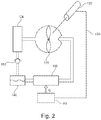
- FIG. 2 illustrates further details the power transformer according to embodiments of the present invention.
- FIG. 1 depicts an apparatus 100 which is suitable for cooling an electronic assembly 50 .
- the apparatus 100 comprises: an evaporator 110 for evaporating a cooling medium using heat Q of the electronic assembly 50 and a power transformer 120 for transforming energy stored in the evaporated cooling medium into electric power.
- the cooling medium comprises an evaporating temperature at atmospheric pressure within a temperature range of 50° C. to 80° C. or within 60° C. and 70° C. or about 65° C.
- the evaporator may provide the evaporated cooling medium under high pressure (higher than atmospheric pressure) to the power transformer 120 .
- FIG. 2 depicts further details for the apparatus 100 according to another embodiment of the present invention, wherein the power transformer 120 comprises a generator 122 , a turbine 126 and a condenser 124 .
- a reservoir 140 for the cooling medium is arranged between the condenser 124 and the evaporator 110 to store the liquid cooling medium.
- the embodiment of FIG. 2 comprises an optional feedback line 130 which provides the electricity generated by the generator 122 to the electronic assembly 50 .
- the electronic assembly 50 is, for example, a high-power amplifier that generates a significant amount of heat used to evaporate the cooling medium in the evaporator 110 .
- the pressurized evaporated cooling medium is fed from the evaporator 110 to the turbine 126 .
- the pressure of the evaporated cooling medium is decreased, thereby driving the turbine 126 and transporting the at least partially de-pressured cooling medium to the condenser 124 .
- the condenser 124 the evaporated cooling medium is condensed to change its phase back to the liquid phase.
- a check valve 150 may be provided between the condenser 124 and the reservoir 140 to prevent any back flow of cooling medium into the condenser 124 from the reservoir 140 (e.g. driven by the pressure generated by the evaporator 110 ).
- the rotating turbine 126 drives the generator 122 which generates electricity which then is fed back via the line 130 to the electronic assembly 50 .
- the turbine 126 comprises, for example, a channel for the cooling medium with a diameter of 5 mm . . . 15 mm or within a range of 3 mm to 20 mm so that it may be a microturbine that can be integrated into the electronic assembly. It is understood that the dimensions of the turbine 126 or the evaporator 110 will be adapted to the particular electronic assembly 50 , e.g. to achieve a compact design.
- the evaporator 110 can, for example, be placed directly on a fan plate of the electronic assembly 50 , thereby absorbing the heat energy generated by the electronic assembly 50 .
- the turbine 126 may be formed as MEMS turbine.
- the overall system with the evaporator 110 and the power transformer 120 may be integrated together into one unit so that the resulting cooling system may be easily placed directly on the electronic assembly.
- the whole cooling system may be formed as small as a couple of centimeters.
- Embodiments may include only the turbine 126 as a MEMS device, but no pumps or compressors.
- the circulation of the cooling medium may only be gravity driven (in the liquid phase) or thermally driven (in the gaseous phase). Therefore, there is no need for any active device that enables the circulation and which would need further energy.
- embodiments do not need any additional heat source to drive the circulation.
- the heat of the electronic assembly 50 may suffice to drive the circulation. Therefore, embodiments are of particular advantage for power electronic assemblies 50 that generate sufficient heat.
- the fluid line from the evaporator 100 is not in thermal contact—or at least not in direct thermal contact—to the fluid line from condenser 124 to the reservoir 140 or to the evaporator 110 (like in vortex devices). This increases the efficiency, because the fluid (cooling medium) is not reheated during the transport from the condenser 124 to the evaporator 110 .
- the reservoir 140 may be on the same level as the evaporation 110 to provide a continuous cool liquid flow to the evaporator 110 , without the need of a pump.
- cooling medium it is of advantage to use a medium that evaporates at a temperature of about 65° C. or within a range between 50° C. and 80° C.
- a possible material would be, for example, methanol or any other mixture of an alcohol with a certain amount of water.
Landscapes
- Engineering & Computer Science (AREA)
- Microelectronics & Electronic Packaging (AREA)
- Physics & Mathematics (AREA)
- Thermal Sciences (AREA)
- Chemical & Material Sciences (AREA)
- Combustion & Propulsion (AREA)
- Mechanical Engineering (AREA)
- General Engineering & Computer Science (AREA)
- Cooling Or The Like Of Electrical Apparatus (AREA)
- Cooling Or The Like Of Semiconductors Or Solid State Devices (AREA)
- Micromachines (AREA)
- Engine Equipment That Uses Special Cycles (AREA)
Applications Claiming Priority (3)
| Application Number | Priority Date | Filing Date | Title |
|---|---|---|---|
| EP18193184.1A EP3620621B1 (fr) | 2018-09-07 | 2018-09-07 | Appareil et procédé de refroidissement d'un ensemble électronique |
| EP18193184 | 2018-09-07 | ||
| EP18193184.1 | 2018-09-07 |
Publications (2)
| Publication Number | Publication Date |
|---|---|
| US20200084916A1 US20200084916A1 (en) | 2020-03-12 |
| US10856440B2 true US10856440B2 (en) | 2020-12-01 |
Family
ID=63528602
Family Applications (1)
| Application Number | Title | Priority Date | Filing Date |
|---|---|---|---|
| US16/563,343 Active US10856440B2 (en) | 2018-09-07 | 2019-09-06 | Apparatus and method for cooling an electronic assembly |
Country Status (3)
| Country | Link |
|---|---|
| US (1) | US10856440B2 (fr) |
| EP (1) | EP3620621B1 (fr) |
| JP (1) | JP7349854B2 (fr) |
Families Citing this family (1)
| Publication number | Priority date | Publication date | Assignee | Title |
|---|---|---|---|---|
| US20230400263A1 (en) * | 2022-06-13 | 2023-12-14 | Hamilton Sundstrand Corporation | Cold plate thermal storage for high load short duration cooling |
Citations (10)
| Publication number | Priority date | Publication date | Assignee | Title |
|---|---|---|---|---|
| US5419780A (en) * | 1994-04-29 | 1995-05-30 | Ast Research, Inc. | Method and apparatus for recovering power from semiconductor circuit using thermoelectric device |
| US20030093995A1 (en) | 2001-11-16 | 2003-05-22 | Intel Corporation | Electrical energy-generating heat sink system and method of using same to recharge an energy storage device |
| US6989989B2 (en) * | 2003-06-17 | 2006-01-24 | Utc Power Llc | Power converter cooling |
| US20090120618A1 (en) * | 2007-11-06 | 2009-05-14 | Christoph Konig | Cooling apparatus for a computer system |
| US20090242174A1 (en) | 2008-03-31 | 2009-10-01 | Mccutchen Co. | Vapor vortex heat sink |
| US20100018207A1 (en) * | 2007-03-02 | 2010-01-28 | Victor Juchymenko | Controlled Organic Rankine Cycle System for Recovery and Conversion of Thermal Energy |
| US20100064682A1 (en) * | 2008-04-25 | 2010-03-18 | Dean Kamen | Thermal Energy Recovery System |
| US20130133868A1 (en) * | 2009-11-30 | 2013-05-30 | Matthew Alexander Lehar | Direct evaporator system and method for organic rankine cycle systems |
| US20130286591A1 (en) | 2012-04-30 | 2013-10-31 | General Electric Company | Power Electronics Cooling |
| US20180252120A1 (en) * | 2015-09-08 | 2018-09-06 | Atlas Copco Airpower, Naamloze Vennootschap | Orc for transforming waste heat from a heat source into mechanical energy and cooling system making use of such an orc |
Family Cites Families (1)
| Publication number | Priority date | Publication date | Assignee | Title |
|---|---|---|---|---|
| JPS58102547A (ja) * | 1981-12-14 | 1983-06-18 | Mitsubishi Electric Corp | サイリスタの冷却装置 |
-
2018
- 2018-09-07 EP EP18193184.1A patent/EP3620621B1/fr active Active
-
2019
- 2019-09-06 JP JP2019162652A patent/JP7349854B2/ja active Active
- 2019-09-06 US US16/563,343 patent/US10856440B2/en active Active
Patent Citations (11)
| Publication number | Priority date | Publication date | Assignee | Title |
|---|---|---|---|---|
| US5419780A (en) * | 1994-04-29 | 1995-05-30 | Ast Research, Inc. | Method and apparatus for recovering power from semiconductor circuit using thermoelectric device |
| US20030093995A1 (en) | 2001-11-16 | 2003-05-22 | Intel Corporation | Electrical energy-generating heat sink system and method of using same to recharge an energy storage device |
| US6989989B2 (en) * | 2003-06-17 | 2006-01-24 | Utc Power Llc | Power converter cooling |
| US7289325B2 (en) * | 2003-06-17 | 2007-10-30 | Utc Power Corporation | Power converter cooling |
| US20100018207A1 (en) * | 2007-03-02 | 2010-01-28 | Victor Juchymenko | Controlled Organic Rankine Cycle System for Recovery and Conversion of Thermal Energy |
| US20090120618A1 (en) * | 2007-11-06 | 2009-05-14 | Christoph Konig | Cooling apparatus for a computer system |
| US20090242174A1 (en) | 2008-03-31 | 2009-10-01 | Mccutchen Co. | Vapor vortex heat sink |
| US20100064682A1 (en) * | 2008-04-25 | 2010-03-18 | Dean Kamen | Thermal Energy Recovery System |
| US20130133868A1 (en) * | 2009-11-30 | 2013-05-30 | Matthew Alexander Lehar | Direct evaporator system and method for organic rankine cycle systems |
| US20130286591A1 (en) | 2012-04-30 | 2013-10-31 | General Electric Company | Power Electronics Cooling |
| US20180252120A1 (en) * | 2015-09-08 | 2018-09-06 | Atlas Copco Airpower, Naamloze Vennootschap | Orc for transforming waste heat from a heat source into mechanical energy and cooling system making use of such an orc |
Non-Patent Citations (1)
| Title |
|---|
| European Search Report issued in European counterpart application No. 18193184.1-1008 dated Mar. 19, 2019 (Seven (7) pages). |
Also Published As
| Publication number | Publication date |
|---|---|
| US20200084916A1 (en) | 2020-03-12 |
| JP2020053682A (ja) | 2020-04-02 |
| JP7349854B2 (ja) | 2023-09-25 |
| EP3620621A1 (fr) | 2020-03-11 |
| EP3620621B1 (fr) | 2022-10-26 |
Similar Documents
| Publication | Publication Date | Title |
|---|---|---|
| US10753236B2 (en) | Fuel vaporization using data center waste heat | |
| US20090120618A1 (en) | Cooling apparatus for a computer system | |
| JP6093856B2 (ja) | オーガニックランキンサイクルの循環流れを用いて電気エネルギーを生成する装置 | |
| EP1985946B1 (fr) | Système de pompe à chaleur et procédé d'opération d'un système de pompe à chaleur | |
| US20120048514A1 (en) | Cooling systems and methods | |
| US12181193B2 (en) | Vapor cycle cooling system for high powered devices | |
| US9801311B2 (en) | Cooling device and electronic device system | |
| US10386091B2 (en) | Water evaporative cooled refrigerant condensing radiator upgrade | |
| CN106628276A (zh) | 一种航天器自驱动两相循环热控制系统 | |
| EP3191773B1 (fr) | Conditionnement d'huile de compresseur de refroidisseur | |
| US10856440B2 (en) | Apparatus and method for cooling an electronic assembly | |
| JP2011210776A (ja) | 液冷式冷却装置 | |
| CN111918535B (zh) | 星载及地面单相流体回路散热系统 | |
| CN105992862A (zh) | 用于运行体积膨胀机的设备和方法 | |
| CN106848478A (zh) | 用于电池的冷却系统及其冷却方法 | |
| CN105115329A (zh) | 一种适应于小空间、多点热源的高效散热系统 | |
| JPH05283571A (ja) | 熱輸送装置 | |
| CN205209305U (zh) | 一种适应于小空间、多点热源的高效散热系统 | |
| JPS6017232A (ja) | ガスタ−ビン式駆動装置 | |
| JP2015035335A (ja) | バッテリの暖機装置 | |
| US20160231032A1 (en) | Piezo Electric and High Voltage Absorption Cooling System | |
| KR20250039302A (ko) | 우회 라인을 포함하는 2상 냉각 시스템을 구비하는 연료 전지 시스템 | |
| CN116625021A (zh) | 无源有机朗肯循环和集成压力模块提供冷却 | |
| CN114440490A (zh) | 一种冷水机组 |
Legal Events
| Date | Code | Title | Description |
|---|---|---|---|
| FEPP | Fee payment procedure |
Free format text: ENTITY STATUS SET TO UNDISCOUNTED (ORIGINAL EVENT CODE: BIG.); ENTITY STATUS OF PATENT OWNER: LARGE ENTITY |
|
| AS | Assignment |
Owner name: HENSOLDT SENSORS GMBH, GERMANY Free format text: ASSIGNMENT OF ASSIGNORS INTEREST;ASSIGNORS:SANDER, JEORG;MOSER, TIM;SIGNING DATES FROM 20190910 TO 20190918;REEL/FRAME:050507/0238 |
|
| STPP | Information on status: patent application and granting procedure in general |
Free format text: RESPONSE TO NON-FINAL OFFICE ACTION ENTERED AND FORWARDED TO EXAMINER |
|
| STPP | Information on status: patent application and granting procedure in general |
Free format text: NOTICE OF ALLOWANCE MAILED -- APPLICATION RECEIVED IN OFFICE OF PUBLICATIONS |
|
| STPP | Information on status: patent application and granting procedure in general |
Free format text: PUBLICATIONS -- ISSUE FEE PAYMENT RECEIVED |
|
| STCF | Information on status: patent grant |
Free format text: PATENTED CASE |
|
| FEPP | Fee payment procedure |
Free format text: MAINTENANCE FEE REMINDER MAILED (ORIGINAL EVENT CODE: REM.); ENTITY STATUS OF PATENT OWNER: LARGE ENTITY |
|
| FEPP | Fee payment procedure |
Free format text: SURCHARGE FOR LATE PAYMENT, LARGE ENTITY (ORIGINAL EVENT CODE: M1554); ENTITY STATUS OF PATENT OWNER: LARGE ENTITY |
|
| MAFP | Maintenance fee payment |
Free format text: PAYMENT OF MAINTENANCE FEE, 4TH YEAR, LARGE ENTITY (ORIGINAL EVENT CODE: M1551); ENTITY STATUS OF PATENT OWNER: LARGE ENTITY Year of fee payment: 4 |