US10843678B2 - Control system having at least one electronic control unit for controlling an internal combustion engine in a hybrid vehicle - Google Patents
Control system having at least one electronic control unit for controlling an internal combustion engine in a hybrid vehicle Download PDFInfo
- Publication number
- US10843678B2 US10843678B2 US15/988,123 US201815988123A US10843678B2 US 10843678 B2 US10843678 B2 US 10843678B2 US 201815988123 A US201815988123 A US 201815988123A US 10843678 B2 US10843678 B2 US 10843678B2
- Authority
- US
- United States
- Prior art keywords
- combustion engine
- situation
- traffic light
- power
- control unit
- Prior art date
- Legal status (The legal status is an assumption and is not a legal conclusion. Google has not performed a legal analysis and makes no representation as to the accuracy of the status listed.)
- Active
Links
- 238000002485 combustion reaction Methods 0.000 title claims abstract description 76
- 230000003993 interaction Effects 0.000 claims abstract description 29
- 230000008859 change Effects 0.000 claims abstract description 26
- 230000007704 transition Effects 0.000 claims description 15
- 230000001133 acceleration Effects 0.000 claims description 11
- 230000009467 reduction Effects 0.000 claims description 7
- 230000003044 adaptive effect Effects 0.000 abstract description 2
- 238000000034 method Methods 0.000 description 9
- 238000006243 chemical reaction Methods 0.000 description 7
- 238000004393 prognosis Methods 0.000 description 7
- 230000001419 dependent effect Effects 0.000 description 5
- 230000006870 function Effects 0.000 description 5
- 238000011017 operating method Methods 0.000 description 4
- 230000008569 process Effects 0.000 description 4
- 230000006399 behavior Effects 0.000 description 3
- 230000008901 benefit Effects 0.000 description 3
- 238000009434 installation Methods 0.000 description 3
- 230000004044 response Effects 0.000 description 3
- 238000011156 evaluation Methods 0.000 description 2
- 238000012546 transfer Methods 0.000 description 2
- 102100034112 Alkyldihydroxyacetonephosphate synthase, peroxisomal Human genes 0.000 description 1
- 101000799143 Homo sapiens Alkyldihydroxyacetonephosphate synthase, peroxisomal Proteins 0.000 description 1
- 238000000848 angular dependent Auger electron spectroscopy Methods 0.000 description 1
- 230000000779 depleting effect Effects 0.000 description 1
- 238000001514 detection method Methods 0.000 description 1
- 238000010586 diagram Methods 0.000 description 1
- 230000000694 effects Effects 0.000 description 1
- 238000004519 manufacturing process Methods 0.000 description 1
- 238000012986 modification Methods 0.000 description 1
- 230000004048 modification Effects 0.000 description 1
- 238000005457 optimization Methods 0.000 description 1
- 238000011084 recovery Methods 0.000 description 1
- 230000000717 retained effect Effects 0.000 description 1
- 230000000630 rising effect Effects 0.000 description 1
- 239000000126 substance Substances 0.000 description 1
- 230000002123 temporal effect Effects 0.000 description 1
Images


Classifications
-
- B—PERFORMING OPERATIONS; TRANSPORTING
- B60—VEHICLES IN GENERAL
- B60W—CONJOINT CONTROL OF VEHICLE SUB-UNITS OF DIFFERENT TYPE OR DIFFERENT FUNCTION; CONTROL SYSTEMS SPECIALLY ADAPTED FOR HYBRID VEHICLES; ROAD VEHICLE DRIVE CONTROL SYSTEMS FOR PURPOSES NOT RELATED TO THE CONTROL OF A PARTICULAR SUB-UNIT
- B60W10/00—Conjoint control of vehicle sub-units of different type or different function
- B60W10/04—Conjoint control of vehicle sub-units of different type or different function including control of propulsion units
- B60W10/06—Conjoint control of vehicle sub-units of different type or different function including control of propulsion units including control of combustion engines
-
- B—PERFORMING OPERATIONS; TRANSPORTING
- B60—VEHICLES IN GENERAL
- B60K—ARRANGEMENT OR MOUNTING OF PROPULSION UNITS OR OF TRANSMISSIONS IN VEHICLES; ARRANGEMENT OR MOUNTING OF PLURAL DIVERSE PRIME-MOVERS IN VEHICLES; AUXILIARY DRIVES FOR VEHICLES; INSTRUMENTATION OR DASHBOARDS FOR VEHICLES; ARRANGEMENTS IN CONNECTION WITH COOLING, AIR INTAKE, GAS EXHAUST OR FUEL SUPPLY OF PROPULSION UNITS IN VEHICLES
- B60K6/00—Arrangement or mounting of plural diverse prime-movers for mutual or common propulsion, e.g. hybrid propulsion systems comprising electric motors and internal combustion engines ; Control systems therefor, i.e. systems controlling two or more prime movers, or controlling one of these prime movers and any of the transmission, drive or drive units Informative references: mechanical gearings with secondary electric drive F16H3/72; arrangements for handling mechanical energy structurally associated with the dynamo-electric machine H02K7/00; machines comprising structurally interrelated motor and generator parts H02K51/00; dynamo-electric machines not otherwise provided for in H02K see H02K99/00
- B60K6/20—Arrangement or mounting of plural diverse prime-movers for mutual or common propulsion, e.g. hybrid propulsion systems comprising electric motors and internal combustion engines ; Control systems therefor, i.e. systems controlling two or more prime movers, or controlling one of these prime movers and any of the transmission, drive or drive units Informative references: mechanical gearings with secondary electric drive F16H3/72; arrangements for handling mechanical energy structurally associated with the dynamo-electric machine H02K7/00; machines comprising structurally interrelated motor and generator parts H02K51/00; dynamo-electric machines not otherwise provided for in H02K see H02K99/00 the prime-movers consisting of electric motors and internal combustion engines, e.g. HEVs
- B60K6/22—Arrangement or mounting of plural diverse prime-movers for mutual or common propulsion, e.g. hybrid propulsion systems comprising electric motors and internal combustion engines ; Control systems therefor, i.e. systems controlling two or more prime movers, or controlling one of these prime movers and any of the transmission, drive or drive units Informative references: mechanical gearings with secondary electric drive F16H3/72; arrangements for handling mechanical energy structurally associated with the dynamo-electric machine H02K7/00; machines comprising structurally interrelated motor and generator parts H02K51/00; dynamo-electric machines not otherwise provided for in H02K see H02K99/00 the prime-movers consisting of electric motors and internal combustion engines, e.g. HEVs characterised by apparatus, components or means specially adapted for HEVs
- B60K6/24—Arrangement or mounting of plural diverse prime-movers for mutual or common propulsion, e.g. hybrid propulsion systems comprising electric motors and internal combustion engines ; Control systems therefor, i.e. systems controlling two or more prime movers, or controlling one of these prime movers and any of the transmission, drive or drive units Informative references: mechanical gearings with secondary electric drive F16H3/72; arrangements for handling mechanical energy structurally associated with the dynamo-electric machine H02K7/00; machines comprising structurally interrelated motor and generator parts H02K51/00; dynamo-electric machines not otherwise provided for in H02K see H02K99/00 the prime-movers consisting of electric motors and internal combustion engines, e.g. HEVs characterised by apparatus, components or means specially adapted for HEVs characterised by the combustion engines
-
- B—PERFORMING OPERATIONS; TRANSPORTING
- B60—VEHICLES IN GENERAL
- B60K—ARRANGEMENT OR MOUNTING OF PROPULSION UNITS OR OF TRANSMISSIONS IN VEHICLES; ARRANGEMENT OR MOUNTING OF PLURAL DIVERSE PRIME-MOVERS IN VEHICLES; AUXILIARY DRIVES FOR VEHICLES; INSTRUMENTATION OR DASHBOARDS FOR VEHICLES; ARRANGEMENTS IN CONNECTION WITH COOLING, AIR INTAKE, GAS EXHAUST OR FUEL SUPPLY OF PROPULSION UNITS IN VEHICLES
- B60K6/00—Arrangement or mounting of plural diverse prime-movers for mutual or common propulsion, e.g. hybrid propulsion systems comprising electric motors and internal combustion engines ; Control systems therefor, i.e. systems controlling two or more prime movers, or controlling one of these prime movers and any of the transmission, drive or drive units Informative references: mechanical gearings with secondary electric drive F16H3/72; arrangements for handling mechanical energy structurally associated with the dynamo-electric machine H02K7/00; machines comprising structurally interrelated motor and generator parts H02K51/00; dynamo-electric machines not otherwise provided for in H02K see H02K99/00
- B60K6/20—Arrangement or mounting of plural diverse prime-movers for mutual or common propulsion, e.g. hybrid propulsion systems comprising electric motors and internal combustion engines ; Control systems therefor, i.e. systems controlling two or more prime movers, or controlling one of these prime movers and any of the transmission, drive or drive units Informative references: mechanical gearings with secondary electric drive F16H3/72; arrangements for handling mechanical energy structurally associated with the dynamo-electric machine H02K7/00; machines comprising structurally interrelated motor and generator parts H02K51/00; dynamo-electric machines not otherwise provided for in H02K see H02K99/00 the prime-movers consisting of electric motors and internal combustion engines, e.g. HEVs
- B60K6/22—Arrangement or mounting of plural diverse prime-movers for mutual or common propulsion, e.g. hybrid propulsion systems comprising electric motors and internal combustion engines ; Control systems therefor, i.e. systems controlling two or more prime movers, or controlling one of these prime movers and any of the transmission, drive or drive units Informative references: mechanical gearings with secondary electric drive F16H3/72; arrangements for handling mechanical energy structurally associated with the dynamo-electric machine H02K7/00; machines comprising structurally interrelated motor and generator parts H02K51/00; dynamo-electric machines not otherwise provided for in H02K see H02K99/00 the prime-movers consisting of electric motors and internal combustion engines, e.g. HEVs characterised by apparatus, components or means specially adapted for HEVs
- B60K6/26—Arrangement or mounting of plural diverse prime-movers for mutual or common propulsion, e.g. hybrid propulsion systems comprising electric motors and internal combustion engines ; Control systems therefor, i.e. systems controlling two or more prime movers, or controlling one of these prime movers and any of the transmission, drive or drive units Informative references: mechanical gearings with secondary electric drive F16H3/72; arrangements for handling mechanical energy structurally associated with the dynamo-electric machine H02K7/00; machines comprising structurally interrelated motor and generator parts H02K51/00; dynamo-electric machines not otherwise provided for in H02K see H02K99/00 the prime-movers consisting of electric motors and internal combustion engines, e.g. HEVs characterised by apparatus, components or means specially adapted for HEVs characterised by the motors or the generators
-
- B—PERFORMING OPERATIONS; TRANSPORTING
- B60—VEHICLES IN GENERAL
- B60W—CONJOINT CONTROL OF VEHICLE SUB-UNITS OF DIFFERENT TYPE OR DIFFERENT FUNCTION; CONTROL SYSTEMS SPECIALLY ADAPTED FOR HYBRID VEHICLES; ROAD VEHICLE DRIVE CONTROL SYSTEMS FOR PURPOSES NOT RELATED TO THE CONTROL OF A PARTICULAR SUB-UNIT
- B60W10/00—Conjoint control of vehicle sub-units of different type or different function
- B60W10/04—Conjoint control of vehicle sub-units of different type or different function including control of propulsion units
- B60W10/08—Conjoint control of vehicle sub-units of different type or different function including control of propulsion units including control of electric propulsion units, e.g. motors or generators
-
- B—PERFORMING OPERATIONS; TRANSPORTING
- B60—VEHICLES IN GENERAL
- B60W—CONJOINT CONTROL OF VEHICLE SUB-UNITS OF DIFFERENT TYPE OR DIFFERENT FUNCTION; CONTROL SYSTEMS SPECIALLY ADAPTED FOR HYBRID VEHICLES; ROAD VEHICLE DRIVE CONTROL SYSTEMS FOR PURPOSES NOT RELATED TO THE CONTROL OF A PARTICULAR SUB-UNIT
- B60W20/00—Control systems specially adapted for hybrid vehicles
- B60W20/10—Controlling the power contribution of each of the prime movers to meet required power demand
- B60W20/12—Controlling the power contribution of each of the prime movers to meet required power demand using control strategies taking into account route information
-
- B—PERFORMING OPERATIONS; TRANSPORTING
- B60—VEHICLES IN GENERAL
- B60W—CONJOINT CONTROL OF VEHICLE SUB-UNITS OF DIFFERENT TYPE OR DIFFERENT FUNCTION; CONTROL SYSTEMS SPECIALLY ADAPTED FOR HYBRID VEHICLES; ROAD VEHICLE DRIVE CONTROL SYSTEMS FOR PURPOSES NOT RELATED TO THE CONTROL OF A PARTICULAR SUB-UNIT
- B60W50/00—Details of control systems for road vehicle drive control not related to the control of a particular sub-unit, e.g. process diagnostic or vehicle driver interfaces
- B60W50/0097—Predicting future conditions
-
- F—MECHANICAL ENGINEERING; LIGHTING; HEATING; WEAPONS; BLASTING
- F02—COMBUSTION ENGINES; HOT-GAS OR COMBUSTION-PRODUCT ENGINE PLANTS
- F02N—STARTING OF COMBUSTION ENGINES; STARTING AIDS FOR SUCH ENGINES, NOT OTHERWISE PROVIDED FOR
- F02N11/00—Starting of engines by means of electric motors
- F02N11/08—Circuits or control means specially adapted for starting of engines
- F02N11/0814—Circuits or control means specially adapted for starting of engines comprising means for controlling automatic idle-start-stop
- F02N11/0818—Conditions for starting or stopping the engine or for deactivating the idle-start-stop mode
- F02N11/0822—Conditions for starting or stopping the engine or for deactivating the idle-start-stop mode related to action of the driver
-
- F—MECHANICAL ENGINEERING; LIGHTING; HEATING; WEAPONS; BLASTING
- F02—COMBUSTION ENGINES; HOT-GAS OR COMBUSTION-PRODUCT ENGINE PLANTS
- F02N—STARTING OF COMBUSTION ENGINES; STARTING AIDS FOR SUCH ENGINES, NOT OTHERWISE PROVIDED FOR
- F02N11/00—Starting of engines by means of electric motors
- F02N11/08—Circuits or control means specially adapted for starting of engines
- F02N11/0814—Circuits or control means specially adapted for starting of engines comprising means for controlling automatic idle-start-stop
- F02N11/0818—Conditions for starting or stopping the engine or for deactivating the idle-start-stop mode
- F02N11/0833—Vehicle conditions
- F02N11/0837—Environmental conditions thereof, e.g. traffic, weather or road conditions
-
- B—PERFORMING OPERATIONS; TRANSPORTING
- B60—VEHICLES IN GENERAL
- B60K—ARRANGEMENT OR MOUNTING OF PROPULSION UNITS OR OF TRANSMISSIONS IN VEHICLES; ARRANGEMENT OR MOUNTING OF PLURAL DIVERSE PRIME-MOVERS IN VEHICLES; AUXILIARY DRIVES FOR VEHICLES; INSTRUMENTATION OR DASHBOARDS FOR VEHICLES; ARRANGEMENTS IN CONNECTION WITH COOLING, AIR INTAKE, GAS EXHAUST OR FUEL SUPPLY OF PROPULSION UNITS IN VEHICLES
- B60K6/00—Arrangement or mounting of plural diverse prime-movers for mutual or common propulsion, e.g. hybrid propulsion systems comprising electric motors and internal combustion engines ; Control systems therefor, i.e. systems controlling two or more prime movers, or controlling one of these prime movers and any of the transmission, drive or drive units Informative references: mechanical gearings with secondary electric drive F16H3/72; arrangements for handling mechanical energy structurally associated with the dynamo-electric machine H02K7/00; machines comprising structurally interrelated motor and generator parts H02K51/00; dynamo-electric machines not otherwise provided for in H02K see H02K99/00
- B60K6/20—Arrangement or mounting of plural diverse prime-movers for mutual or common propulsion, e.g. hybrid propulsion systems comprising electric motors and internal combustion engines ; Control systems therefor, i.e. systems controlling two or more prime movers, or controlling one of these prime movers and any of the transmission, drive or drive units Informative references: mechanical gearings with secondary electric drive F16H3/72; arrangements for handling mechanical energy structurally associated with the dynamo-electric machine H02K7/00; machines comprising structurally interrelated motor and generator parts H02K51/00; dynamo-electric machines not otherwise provided for in H02K see H02K99/00 the prime-movers consisting of electric motors and internal combustion engines, e.g. HEVs
- B60K6/22—Arrangement or mounting of plural diverse prime-movers for mutual or common propulsion, e.g. hybrid propulsion systems comprising electric motors and internal combustion engines ; Control systems therefor, i.e. systems controlling two or more prime movers, or controlling one of these prime movers and any of the transmission, drive or drive units Informative references: mechanical gearings with secondary electric drive F16H3/72; arrangements for handling mechanical energy structurally associated with the dynamo-electric machine H02K7/00; machines comprising structurally interrelated motor and generator parts H02K51/00; dynamo-electric machines not otherwise provided for in H02K see H02K99/00 the prime-movers consisting of electric motors and internal combustion engines, e.g. HEVs characterised by apparatus, components or means specially adapted for HEVs
- B60K6/26—Arrangement or mounting of plural diverse prime-movers for mutual or common propulsion, e.g. hybrid propulsion systems comprising electric motors and internal combustion engines ; Control systems therefor, i.e. systems controlling two or more prime movers, or controlling one of these prime movers and any of the transmission, drive or drive units Informative references: mechanical gearings with secondary electric drive F16H3/72; arrangements for handling mechanical energy structurally associated with the dynamo-electric machine H02K7/00; machines comprising structurally interrelated motor and generator parts H02K51/00; dynamo-electric machines not otherwise provided for in H02K see H02K99/00 the prime-movers consisting of electric motors and internal combustion engines, e.g. HEVs characterised by apparatus, components or means specially adapted for HEVs characterised by the motors or the generators
- B60K2006/268—Electric drive motor starts the engine, i.e. used as starter motor
-
- B—PERFORMING OPERATIONS; TRANSPORTING
- B60—VEHICLES IN GENERAL
- B60W—CONJOINT CONTROL OF VEHICLE SUB-UNITS OF DIFFERENT TYPE OR DIFFERENT FUNCTION; CONTROL SYSTEMS SPECIALLY ADAPTED FOR HYBRID VEHICLES; ROAD VEHICLE DRIVE CONTROL SYSTEMS FOR PURPOSES NOT RELATED TO THE CONTROL OF A PARTICULAR SUB-UNIT
- B60W50/00—Details of control systems for road vehicle drive control not related to the control of a particular sub-unit, e.g. process diagnostic or vehicle driver interfaces
- B60W2050/0062—Adapting control system settings
- B60W2050/007—Switching between manual and automatic parameter input, and vice versa
- B60W2050/0073—Driver overrides controller
-
- B—PERFORMING OPERATIONS; TRANSPORTING
- B60—VEHICLES IN GENERAL
- B60W—CONJOINT CONTROL OF VEHICLE SUB-UNITS OF DIFFERENT TYPE OR DIFFERENT FUNCTION; CONTROL SYSTEMS SPECIALLY ADAPTED FOR HYBRID VEHICLES; ROAD VEHICLE DRIVE CONTROL SYSTEMS FOR PURPOSES NOT RELATED TO THE CONTROL OF A PARTICULAR SUB-UNIT
- B60W2510/00—Input parameters relating to a particular sub-units
- B60W2510/24—Energy storage means
- B60W2510/242—Energy storage means for electrical energy
- B60W2510/244—Charge state
-
- B—PERFORMING OPERATIONS; TRANSPORTING
- B60—VEHICLES IN GENERAL
- B60W—CONJOINT CONTROL OF VEHICLE SUB-UNITS OF DIFFERENT TYPE OR DIFFERENT FUNCTION; CONTROL SYSTEMS SPECIALLY ADAPTED FOR HYBRID VEHICLES; ROAD VEHICLE DRIVE CONTROL SYSTEMS FOR PURPOSES NOT RELATED TO THE CONTROL OF A PARTICULAR SUB-UNIT
- B60W2520/00—Input parameters relating to overall vehicle dynamics
- B60W2520/10—Longitudinal speed
-
- B—PERFORMING OPERATIONS; TRANSPORTING
- B60—VEHICLES IN GENERAL
- B60W—CONJOINT CONTROL OF VEHICLE SUB-UNITS OF DIFFERENT TYPE OR DIFFERENT FUNCTION; CONTROL SYSTEMS SPECIALLY ADAPTED FOR HYBRID VEHICLES; ROAD VEHICLE DRIVE CONTROL SYSTEMS FOR PURPOSES NOT RELATED TO THE CONTROL OF A PARTICULAR SUB-UNIT
- B60W2540/00—Input parameters relating to occupants
- B60W2540/10—Accelerator pedal position
-
- B—PERFORMING OPERATIONS; TRANSPORTING
- B60—VEHICLES IN GENERAL
- B60W—CONJOINT CONTROL OF VEHICLE SUB-UNITS OF DIFFERENT TYPE OR DIFFERENT FUNCTION; CONTROL SYSTEMS SPECIALLY ADAPTED FOR HYBRID VEHICLES; ROAD VEHICLE DRIVE CONTROL SYSTEMS FOR PURPOSES NOT RELATED TO THE CONTROL OF A PARTICULAR SUB-UNIT
- B60W2555/00—Input parameters relating to exterior conditions, not covered by groups B60W2552/00, B60W2554/00
- B60W2555/60—Traffic rules, e.g. speed limits or right of way
-
- B—PERFORMING OPERATIONS; TRANSPORTING
- B60—VEHICLES IN GENERAL
- B60W—CONJOINT CONTROL OF VEHICLE SUB-UNITS OF DIFFERENT TYPE OR DIFFERENT FUNCTION; CONTROL SYSTEMS SPECIALLY ADAPTED FOR HYBRID VEHICLES; ROAD VEHICLE DRIVE CONTROL SYSTEMS FOR PURPOSES NOT RELATED TO THE CONTROL OF A PARTICULAR SUB-UNIT
- B60W2720/00—Output or target parameters relating to overall vehicle dynamics
- B60W2720/10—Longitudinal speed
- B60W2720/103—Speed profile
-
- F—MECHANICAL ENGINEERING; LIGHTING; HEATING; WEAPONS; BLASTING
- F02—COMBUSTION ENGINES; HOT-GAS OR COMBUSTION-PRODUCT ENGINE PLANTS
- F02N—STARTING OF COMBUSTION ENGINES; STARTING AIDS FOR SUCH ENGINES, NOT OTHERWISE PROVIDED FOR
- F02N2200/00—Parameters used for control of starting apparatus
- F02N2200/08—Parameters used for control of starting apparatus said parameters being related to the vehicle or its components
- F02N2200/0801—Vehicle speed
-
- F—MECHANICAL ENGINEERING; LIGHTING; HEATING; WEAPONS; BLASTING
- F02—COMBUSTION ENGINES; HOT-GAS OR COMBUSTION-PRODUCT ENGINE PLANTS
- F02N—STARTING OF COMBUSTION ENGINES; STARTING AIDS FOR SUCH ENGINES, NOT OTHERWISE PROVIDED FOR
- F02N2200/00—Parameters used for control of starting apparatus
- F02N2200/10—Parameters used for control of starting apparatus said parameters being related to driver demands or status
- F02N2200/101—Accelerator pedal position
-
- F—MECHANICAL ENGINEERING; LIGHTING; HEATING; WEAPONS; BLASTING
- F02—COMBUSTION ENGINES; HOT-GAS OR COMBUSTION-PRODUCT ENGINE PLANTS
- F02N—STARTING OF COMBUSTION ENGINES; STARTING AIDS FOR SUCH ENGINES, NOT OTHERWISE PROVIDED FOR
- F02N2200/00—Parameters used for control of starting apparatus
- F02N2200/12—Parameters used for control of starting apparatus said parameters being related to the vehicle exterior
- F02N2200/125—Information about other vehicles, traffic lights or traffic congestion
-
- F—MECHANICAL ENGINEERING; LIGHTING; HEATING; WEAPONS; BLASTING
- F02—COMBUSTION ENGINES; HOT-GAS OR COMBUSTION-PRODUCT ENGINE PLANTS
- F02N—STARTING OF COMBUSTION ENGINES; STARTING AIDS FOR SUCH ENGINES, NOT OTHERWISE PROVIDED FOR
- F02N2300/00—Control related aspects of engine starting
- F02N2300/20—Control related aspects of engine starting characterised by the control method
- F02N2300/2006—Control related aspects of engine starting characterised by the control method using prediction of future conditions
-
- Y—GENERAL TAGGING OF NEW TECHNOLOGICAL DEVELOPMENTS; GENERAL TAGGING OF CROSS-SECTIONAL TECHNOLOGIES SPANNING OVER SEVERAL SECTIONS OF THE IPC; TECHNICAL SUBJECTS COVERED BY FORMER USPC CROSS-REFERENCE ART COLLECTIONS [XRACs] AND DIGESTS
- Y02—TECHNOLOGIES OR APPLICATIONS FOR MITIGATION OR ADAPTATION AGAINST CLIMATE CHANGE
- Y02T—CLIMATE CHANGE MITIGATION TECHNOLOGIES RELATED TO TRANSPORTATION
- Y02T10/00—Road transport of goods or passengers
- Y02T10/60—Other road transportation technologies with climate change mitigation effect
- Y02T10/62—Hybrid vehicles
-
- Y02T10/6291—
Definitions
- the invention relates to a control system having at least one electronic control unit for controlling a combustion engine in a hybrid vehicle.
- Hybrid vehicles of this sort have control systems with at least one electronic control unit which carry out various operating procedures for selecting an operating mode appropriate for the respective current driving situation, in particular using appropriately programmed functional modules.
- Selectable operating modes are, in particular, purely electric driving (only the electric motor provides propulsion; “E-mode”, “E-driving”), driving purely with the combustion engine (only the combustion engine provides propulsion) and/or driving with hybrid drive (both the electric motor and the combustion engine provide propulsion).
- Known operating methods prioritize consideration of the charge state of the battery or of another electric store (e.g. a supercap) to select the operating mode.
- Parameters such as the current vehicle speed, the current driving behavior, or particular currently set customer functions are also partially taken into account here.
- a control system with at least one electronic control unit for controlling a combustion engine in a hybrid vehicle, wherein the control unit is designed in such a way that it evaluates input signals for detecting data for identifying a current situation and for identifying at least one situation forecast in the near future with regard to an expected speed curve and/or power curve, and that it controls the restarting or shutting off of the combustion engine on the occurrence of a power-related driver interaction in the current situation independently of a currently specified E-travel speed limit and/or power limit when it identifies a traffic light phase and its duration as a situation forecast in the near future.
- control unit for controlling a combustion engine in a hybrid vehicle
- the control unit is designed in such a way that it evaluates input signals for detecting data for identifying a current situation and for identifying at least one situation prevailing in the near future with regard to an expected speed curve and a predicted traffic light phase change and, depending thereon and on a power-related driver interaction, controls, in a manner that is adaptive to the situation, the restart and shut-off of the combustion engine independently of a currently predefined E-travel speed limit and/or power limit.
- the invention comprises a method for controlling the restart and the shut-off of a combustion engine in a hybrid vehicle, wherein by way of an evaluation of the current situation and of forthcoming situations, preferably in a defined forecast range, in view of an expected speed curve and preferably also of a power curve depending on a driver interaction and/or on the charge state of the high-voltage store, the restart and shut-off behavior is optimized in a defined manner which will be considered further in more detail below.
- fundamentally data is detected for identifying a current situation and for identifying at least one situation prevailing in the near future (e.g. a defined forecast horizon ⁇ 5 km) and evaluated in relation to the expected speed curve.
- data for forecasting the speed curve comprise, in particular:
- map data about the surroundings and/or traffic guidance information from navigation systems e.g. ADAS with RTTI
- navigation systems e.g. ADAS with RTTI
- driver-specific learning systems for the prognosis of the most probable forthcoming route, for the prognosis of speeds in forthcoming curves, for detecting forthcoming and current speed limits, for the prognosis of the forthcoming gradient curve of the route, for the prognosis of the average speed depending on the traffic density on the forthcoming route etc.
- sign recognition systems e.g.
- KAFAS KAFAS
- camera systems for detecting the current state of the forthcoming and relevant signal light installation (identification of the traffic light state) as well as (learning) systems in the vehicle or via a backend for the temporal prognosis of the relevant signal light installations (forecast of the traffic light state)
- vehicle sensors e.g. radar and KAFAS
- all further systems that could contribute to a prognosis of the expected speed curve.
- At least one power-related driver interaction is determined, in particular through the detection of the accelerator pedal position of the respective current wanted power.
- the restart and shut-off of the combustion engine is controlled primarily depending on the expected speed curve in the predefined forecast horizon and on the current power-related driver interaction.
- the restart and shut-off behavior can be optimized depending on the operating state of the vehicle, such as in particular the charge state of the high high-voltage store.
- the expected speed curve and power curve are in particular considered, and not only the current speed and the current power in view of these limits which formerly were set rigidly.
- the new situation(s) prevailing in the near future can lead according to the invention to the (continuously variable) shift upwards and downwards and/or to ignoring these formerly situation-independent predetermined restart limits.
- control by way of the control system according to the invention, or the method according to the invention for controlling the restart or the shut-off of a combustion engine, is carried out in a defined manner, namely preferably in such a way that
- the control system according to the invention focuses on the application of a traffic light phase prediction system which is known per se (cf. e.g. the applicant's unpublished DE 10 2016 210071.8), but which can, likewise, be developed further.
- a traffic light phase prediction system it is possible, for example, by means of traffic light phases whose times have been learned, or by means of a transmitting infrastructure (in particular traffic light installations) for the duration before a change of the traffic light phase to be predetermined.
- the system according to the invention is fitted with a receiving and evaluation unit for such infrastructure data of a usual type known per se.
- the electronic control unit accesses this infrastructure data.
- input signals for detecting data, for identifying a current situation and for identifying at least one situation prevailing in the near future in respect of an expected speed curve are evaluated, in particular by an appropriately designed and programmed control unit.
- the restart or shut-off of the combustion engine is controlled on the occurrence of a power(load)-related driver interaction (e.g. on releasing the accelerator pedal or pushing the accelerator pedal down) in the current situation, independently of a currently predetermined E-driving speed limit, if a traffic light phase change is identified or expected as a situation prevailing in the near future by a traffic light phase prediction system.
- FIG. 1 is a schematic diagram of the important necessary functional components for carrying out the operating method underlying the control system.
- FIG. 2 graphically illustrates an Example 1: shows the current situation assuming the combustion engine is running and the traffic light phase is red; first situation in the near future: change to a green traffic light phase after a long deceleration (if the duration of the deceleration is long enough); second situation with an expected speed (e.g. speed limit) above the maximum E-travel speed.
- an expected speed e.g. speed limit
- FIG. 3 graphically illustrates an Example 2: shows the current situation assuming the combustion engine is running and the traffic light phase is red; first situation in the near future: change to a green traffic light phase after a short deceleration (if the duration of the deceleration is not long enough); second situation with an expected speed above the maximum E-travel speed.
- FIG. 4 graphically illustrates an Example 3: shows the current situation assuming the combustion engine is running and the traffic light phase is red; first situation in the near future: Case 1 with change to a green traffic light phase after a long deceleration (if the duration of the deceleration is long enough), e.g. because of a reaction of the driver to a phased traffic light assistant, and case 2 with change to a green traffic light phase after a short deceleration (if the duration of the deceleration is not long enough), because there is no reaction of the driver to the phased traffic light assistant; second situation with an expected speed above the maximum E-travel speed.
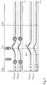
- FIG. 5 graphically illustrates an Example 4: shows the current situation assuming the combustion engine is running and the traffic light phase is red; first situation in the near future: Case 1 (above) with change to a green traffic light phase and case 2 (below) with remaining in a red traffic light phase—both cases with comparatively long decelerations and accelerations with only achieving a new target speed above the maximum E-travel speed in the second situation (S 2 ) in the near future.
- FIG. 6 graphically illustrates an Example 5: shows the current situation assuming the combustion engine is running and the traffic light phase is amber; first situation in the near future: change to red traffic light phase of sufficient duration, in which operation of the combustion engine is not necessary (total of deceleration and stationary time).
- FIG. 7 graphically illustrates an Example 6: shows the current situation assuming the combustion engine is shut off and the traffic light phase is green; first situation in the near future: change to (red traffic light phase above) amber traffic light phase—leads to a short power increase.
- FIG. 8 graphically illustrates an Example 7: shows the current situation assuming combustion engine is running; first situation, entering into an E-travel zone with early shut-off when power is removed (F ⁇ ), since after the traffic light (situation 2 ) is definitively known, the target speed lies below the maximum E-travel speed.
- FIG. 9 graphically illustrates an Example 8: shows the current situation assuming combustion engine switched off (i.e. travel at a speed below the maximum E-travel speed); first situation is a journey out of the city after a green traffic light with early restart at increased power (F+) or start of the acceleration.
- a sensor system 1 of the vehicle itself consisting for example of a camera and a front radar for identifying traffic signs and vehicles in front, as well as a navigation system 2 for identifying traffic guidance and predicted traffic jams, are illustrated in FIG. 1 .
- the sensor system 1 also comprises sensors for traffic light identification and/or traffic light prognosis.
- the traffic light forecast can also be implemented or supported by a learning back-end system.
- a traffic light forecast can be included in the determination of the expected speed curve.
- the data of these two systems 1 and 2 are input signals of a forecast module 3 .
- the forecast module 3 is designed to determine an expected speed curve v e and/or a power curve on the basis of this data, and can be a function module of an electronic control unit not illustrated here in more detail.
- an accelerator pedal sensor 4 is, for example, provided here, whose output signal FP reflects the current wanted power, or the wanted power curve, of the driver. Changes of power-reducing and power-increasing driver interactions via the accelerator pedal 4 are in particular relevant here for the invention.
- the output signal FP and the expected speed curve v e determined in the forecast module 3 are input signals of a control function module 5 which is also part of the control unit.
- a software program product is preferably contained in the control function module 5 , through which the operating strategy of the control system according to the invention is realized.
- the operating strategy is built on the following prior art: If the actual speed falls below the currently valid E-travel speed limit eV Max , the combustion engine is shut off according to the prior art. If the actual speed exceeds the currently valid E-travel speed limit eV Max , the combustion engine is immediately restarted according to the prior art. The same applies when exceeding or falling below the speed-dependent and charge-state-dependent defined restart or shut-off limits through power wishes on the part of the driver.
- the expected speed curve v e and/or, similarly, the expected power curve are taken into consideration by the invention in view of these limits which formerly were rigidly set.
- expected speed curves v e for a first situation S 1 in the near future and, possibly, also for a second situation S 2 in the near future, are illustrated in FIGS. 2 to 9 . These three situations lie in a defined forecast horizon of, for example, about 2 km.
- the operating strategy according to the prior art is shown above using the speed curves v e , with the overlaid illustration of a combustion engine that is restarted or shut off.
- the operating strategy according to the invention is respectively shown similarly below.
- the speed v e with the combustion engine restarted is shown by the solid line
- the speed v e with the combustion engine shut off is shown by the dashed line.
- steady travel in each case with 100 km/h as the upper example, and in each case 70 km/h as the lower example
- the combustion engine switched on is illustrated first as the current situation S 0 .
- the driver performs a power-reducing driver interaction FP ⁇ (e.g. releasing the accelerator pedal), since, for example, he himself or, optionally, a phased traffic light assistant in the vehicle, has currently sighted a red traffic light.
- FP ⁇ power-reducing driver interaction
- the at least one control unit which can also be composed of a plurality of control units ( 3 and 5 in this case), also receives input signals from a traffic light prediction system, known per se, for identifying at least one situation S 1 prevailing in the near future with respect to an expected speed curve v e and a forthcoming change of the traffic light phase.
- a traffic light prediction system known per se
- a change in the traffic light phase to green of which the control unit 3 , 5 can predict the time, takes place at the transfer to the situation S 1 prevailing in the near future.
- duration dt of the reduction of the expected speed curve v e following the driver interaction FP ⁇ until the entry to the first situation S 1 prevailing in the near future is greater than a predetermined minimum duration dt_min, the combustion engine will be shut off straight away with the occurrence of the driver interaction FP ⁇ in the current situation S 0 independently of a currently specified E-travel speed limit eV Max,CD or eV Max,CS (dashed lines).
- FIG. 3 shows an example similar to FIG. 2 , where in this case the duration dt of the reduction of the expected speed curve v e after the driver interaction FP ⁇ until entry to the first situation S 1 prevailing in the near future is smaller than a predetermined minimum duration dt_min, for example because a change in the traffic light phase to green is forthcoming in the near future.
- the combustion engine is not shut off, independently of the maximum E-travel speeds defined according to the prior art. The reason for this is that after the traffic light the expected speed again lies above the maximum E-travel speed, and therefore restarting the combustion engine is necessary in any case. Briefly shutting off the combustion engine is prevented if the specifications through the maximum E-travel speeds are ignored in a manner that depends on the situation and with a forecast consisting of the duration of the traffic light phases and the expected speed after the traffic light.
- FIG. 4 Two cases related to the reaction or the absence of reaction of the driver to a phased traffic light assistant that may be activated are illustrated in FIG. 4 .
- the power-reducing driver interaction F ⁇ 1 according to the invention leads to the combustion engine being shut off, since a change to a green traffic light phase in situation S 1 still lasts sufficiently long that a deceleration starting now will exceed the minimum duration dt_min. This is because the driver reacts promptly here to a phased traffic light assistant which can disclose the green traffic light already in the current situation S 0 .
- case 2 there is no reaction of the driver to the phased traffic light assistant, and the change of the traffic light phase to green also takes place relatively promptly.
- the power-reducing driver interaction F ⁇ 2 does not lead to the combustion engine being shut down, since a change to a green traffic light phase in situation S 1 is soon imminent, and the predetermined minimum duration dt_min is thus not achievable by the power-free deceleration.
- the traffic light phase prediction it is possible to determine the deceleration time, and in particular the power-free time including the stationary time at the traffic light, and thus to decide whether shutting the combustion engine off with the removal of power by the driver is worthwhile from the efficiency point of view.
- the consumption caused by starting the combustion engine is here to be compared with the idling consumption throughout the power-free time (less the time in propulsion operation).
- the length of the power-free period in which the combustion engine can be switched off for efficiency reasons is thus critical. If this time exceeds a minimum duration, it is worth switching off the combustion engine, otherwise it should remain activated.
- FIG. 5 A situation similar to that of FIG. 2 is illustrated in FIG. 5 , wherein in case 1 (above) a change takes place to a green traffic light phase in situation S 1 , and in case 2 (below) the traffic light phase remains red in situation S 1 . Both cases comprise comparatively long decelerations and accelerations with the new target speed only reached in the second situation S 2 .
- the efficiency and the response are increased by considering an approximate, known target speed at the traffic light or at the transition to situation S 1 .
- a change to a red traffic light phase takes place, or the traffic light continues to be red, at the transition to situation S 1 .
- the expected speed curve v e ends at zero at the transition to situation S 1 .
- the combustion engine is shut off at both of the power-reducing driver interactions F ⁇ 1 and F ⁇ 2 , since in both cases no immediate acceleration is expected at the traffic light or at the transition to situation S 1 .
- the efficiency and the E-driving experience are improved by this early shut-off of the combustion engine as a result of the expected deceleration.
- FIG. 7 starts from an E-travel mode in the current situation S 0 .
- the combustion engine which is switched off, is switched on without delay with the power-increasing driver interaction FP+ in the current situation S 0 if a forthcoming change to a red traffic light phase is expected at the transition to the future situation S 1 and, for example, at the same time a larger speed difference, including exceeding the maximum E-travel speed is necessary to pass the traffic light before reaching the red phase and/or the current speed is sufficiently far below the permitted speed limit; it is then assumed that the driver will accelerate in the amber traffic light phase, and will not stop at the red traffic light.
- the operating strategy function implements a restart robustness depending on the current power and speed.
- a power-dependent and ultimately unnecessary and brief restarting of the combustion engine as soon as the driver accelerates does not result.
- the efficiency is increased according to the invention by considering an approximate, known target speed at the traffic light or at the transition to situation S 1 .
- the combustion engine is switched on with the driver interaction FP+, since the speed curve v e to be expected significantly exceeds a specified threshold (here, for example, the upper E-travel speed limit) at the traffic light or at the transition to the situation S 1 , and thus the power is prioritized.
- a specified threshold here, for example, the upper E-travel speed limit
- the combustion engine is not switched on with the driver interaction FP+, since the speed curve v e to be expected does not exceed a specified threshold (here, for example, the lower E-travel speed limit) at the traffic light or at the transition to the situation S 1 , or only does so to an insignificant extent, nor is a large increase in speed expected, and thus the restart robustness is prioritized.
- a specified threshold here, for example, the lower E-travel speed limit
- the current speed before the traffic light is above the maximum E-travel speed, and the predicted speed after the traffic light is below the maximum E-travel speed.
- the state of the traffic light is not relevant—it is only necessary to know that a traffic light is present.
- the engine should immediately be shut off in the target state. At present, this does not take place until falling below the maximum E-travel speed.
- the example illustrates an advantageous measure for improving the efficiency and the E-driving experience, since the full deceleration is driven electrically, and an increased potential recovery is thus also set up.
- the example 8 according to FIG. 9 describes the converse case, when the current speed before the traffic light lies below and the predicted speed after the traffic light lies above the maximum E-travel speed.
- restarting only takes place when the maximum E-travel speed or the E-driving power limit is exceeded.
- the control unit already starts up the combustion engine shortly after the beginning of the acceleration, provided the traffic light changes or has changed to green.
- the traffic light state cannot simply be directly detected by the camera, for which reason a traffic light phase prediction system is needed in order to react appropriately.
- This measure gives rise to the advantage that the response for the acceleration and the restart comfort are increased.
- electric energy of the high-voltage store is saved for later travel segments in which the purely electric travel mode is significantly more efficient than the travel mode with the combustion engine.
Landscapes
- Engineering & Computer Science (AREA)
- Combustion & Propulsion (AREA)
- Chemical & Material Sciences (AREA)
- Mechanical Engineering (AREA)
- Transportation (AREA)
- Automation & Control Theory (AREA)
- General Engineering & Computer Science (AREA)
- Health & Medical Sciences (AREA)
- Atmospheric Sciences (AREA)
- Environmental & Geological Engineering (AREA)
- Toxicology (AREA)
- Life Sciences & Earth Sciences (AREA)
- Human Computer Interaction (AREA)
- Control Of Vehicle Engines Or Engines For Specific Uses (AREA)
- Hybrid Electric Vehicles (AREA)
Abstract
Description
(ii) sign recognition systems (e.g. KAFAS), in particular for identifying traffic signs with effects on the speed to be expected,
(iii) camera systems for detecting the current state of the forthcoming and relevant signal light installation (identification of the traffic light state) as well as (learning) systems in the vehicle or via a backend for the temporal prognosis of the relevant signal light installations (forecast of the traffic light state),
(iv) vehicle sensors (e.g. radar and KAFAS) for detecting other road users in front (in particular the speed and acceleration of the vehicle in front), and/or
(v) all further systems that could contribute to a prognosis of the expected speed curve.
-
- phases in which the combustion engine is only briefly shut-off or only briefly restarted are avoided,
- the E-mode is retained as long as possible when the power is comparatively low, or is avoided with a comparatively high or rising power,
- a restart of the combustion engine is preferably performed at the beginning of acceleration procedures, and not during acceleration procedures and not during steady travel,
- decelerations that are expected to be long are preferably handled with the combustion engine shut-off, and/or
- the number of restart and shut-off procedures while the customer is driving is reduced.
-
- 1) improving the drive experience in E-mode through:
- extending the driving phase in the E-mode (by means of reducing power-dependent restart in an expected low-power situation)
- energy optimization
- restart robustness
- 2) improving comfort, acoustics and customer appreciation of the operating strategy through:
- avoiding brief shut-offs or restarts of the combustion engine
- reduction of shut-off fluctuations
- restart robustness (in the lower speed range)
- reduction of restarting and shut down processes in customer operation
- avoidance of restart processes during steady travel (in part by hiding in accelerations)
- favoring restarts before high-power situations (avoiding high coupling-up speed)
- 3) consumption reduction or range increase through:
- avoiding unnecessary E-mode driving when high power is expected
- reduction of restart losses by avoiding unnecessary shut-off processes
- increased use of recovered energy by shutting the combustion engine off promptly
- 4) improved sportiness or response through:
- avoiding shut-off processes that are only brief before high-power situations
- prompt restarting of the combustion engine before high power requirement
- 1) improving the drive experience in E-mode through:
Claims (6)
Applications Claiming Priority (4)
| Application Number | Priority Date | Filing Date | Title |
|---|---|---|---|
| DE102015223588.2A DE102015223588A1 (en) | 2015-11-27 | 2015-11-27 | Control system with at least one electronic control unit for controlling an internal combustion engine in a hybrid vehicle |
| DE102015223588.2 | 2015-11-27 | ||
| DE102015223588 | 2015-11-27 | ||
| PCT/EP2016/078856 WO2017089569A1 (en) | 2015-11-27 | 2016-11-25 | Control system having at least one electronic control unit for controlling an internal combustion engine in a hybrid vehicle |
Related Parent Applications (1)
| Application Number | Title | Priority Date | Filing Date |
|---|---|---|---|
| PCT/EP2016/078856 Continuation WO2017089569A1 (en) | 2015-11-27 | 2016-11-25 | Control system having at least one electronic control unit for controlling an internal combustion engine in a hybrid vehicle |
Publications (2)
| Publication Number | Publication Date |
|---|---|
| US20180265069A1 US20180265069A1 (en) | 2018-09-20 |
| US10843678B2 true US10843678B2 (en) | 2020-11-24 |
Family
ID=57396453
Family Applications (2)
| Application Number | Title | Priority Date | Filing Date |
|---|---|---|---|
| US15/988,123 Active US10843678B2 (en) | 2015-11-27 | 2018-05-24 | Control system having at least one electronic control unit for controlling an internal combustion engine in a hybrid vehicle |
| US15/988,154 Active US10513252B2 (en) | 2015-11-27 | 2018-05-24 | Control system having at least one electronic control unit for controlling an internal combustion engine in a hybrid vehicle |
Family Applications After (1)
| Application Number | Title | Priority Date | Filing Date |
|---|---|---|---|
| US15/988,154 Active US10513252B2 (en) | 2015-11-27 | 2018-05-24 | Control system having at least one electronic control unit for controlling an internal combustion engine in a hybrid vehicle |
Country Status (5)
| Country | Link |
|---|---|
| US (2) | US10843678B2 (en) |
| EP (2) | EP3380379B1 (en) |
| CN (2) | CN108290575B (en) |
| DE (1) | DE102015223588A1 (en) |
| WO (2) | WO2017089565A1 (en) |
Families Citing this family (12)
| Publication number | Priority date | Publication date | Assignee | Title |
|---|---|---|---|---|
| DE102015223588A1 (en) * | 2015-11-27 | 2017-06-01 | Bayerische Motoren Werke Aktiengesellschaft | Control system with at least one electronic control unit for controlling an internal combustion engine in a hybrid vehicle |
| DE102016200605A1 (en) * | 2016-01-19 | 2017-07-20 | Bayerische Motoren Werke Aktiengesellschaft | Control system with at least one electronic control unit for controlling an internal combustion engine in a hybrid vehicle |
| DE102017202315B4 (en) | 2017-02-14 | 2020-09-03 | Bayerische Motoren Werke Aktiengesellschaft | Method, control unit and control system with at least one electronic control unit for controlling an internal combustion engine in a hybrid vehicle |
| KR102355425B1 (en) * | 2017-09-29 | 2022-01-26 | 현대자동차주식회사 | Hybrid vehicle and method of controlling engine for the same |
| GB2569351B (en) * | 2017-12-14 | 2020-07-29 | Jaguar Land Rover Ltd | Whole journey predictive energy optimisation |
| KR102451896B1 (en) * | 2017-12-18 | 2022-10-06 | 현대자동차 주식회사 | Method for controlling driving of hybrid vehicle using dynamic traffic information |
| US10640104B2 (en) * | 2018-01-30 | 2020-05-05 | GM Global Technology Operations LLC | Anticipatory control for hybrid vehicle propulsion system |
| IT201800003414A1 (en) * | 2018-03-09 | 2019-09-09 | Fpt Motorenforschung Ag | METHOD OF MANAGING A LUBRICATION OF AN INTERNAL COMBUSTION ENGINE AND INTERNAL COMBUSTION ENGINE IMPLEMENTING THE METHOD |
| DE102018212519A1 (en) * | 2018-07-26 | 2020-01-30 | Bayerische Motoren Werke Aktiengesellschaft | Longitudinal driver assistance system in a hybrid vehicle |
| US11650067B2 (en) | 2019-07-08 | 2023-05-16 | Toyota Motor North America, Inc. | System and method for reducing route time using big data |
| DE102021113798B4 (en) | 2021-05-28 | 2023-03-30 | Schaeffler Technologies AG & Co. KG | Electrically operable powertrain, method for controlling an electrically operable powertrain, computer program product and control unit |
| FR3137641A1 (en) * | 2022-07-08 | 2024-01-12 | Vitesco Technologies | METHOD FOR OPTIMIZING THE ENERGY CONSUMPTION OF A VEHICLE |
Citations (20)
| Publication number | Priority date | Publication date | Assignee | Title |
|---|---|---|---|---|
| DE19831487C1 (en) | 1998-07-14 | 2000-03-16 | Daimler Chrysler Ag | Method of operating hybrid vehicle drive with battery involves computing anticipated power requirements over route, determining time plan regulating drives or operating modes accordingly |
| DE10035027A1 (en) | 2000-07-19 | 2002-01-31 | Daimler Chrysler Ag | Method for controlling the operating mode of vehicles with hybrid drives detects a route profile covered by a vehicle while invoking an additional criterion for selecting the operating mode |
| US20030006076A1 (en) | 2000-10-11 | 2003-01-09 | Tamor Michael Alan | Control system for a hybrid electric vehicle to anticipate the need for a mode change |
| FR2863953A1 (en) | 2003-12-23 | 2005-06-24 | Renault Sas | Motor vehicle controlling process, involves utilizing electronic control unit of thermal engine for executing acceleration forecast of vehicle, and transmitting sequence of disconnection or starting operations of engine |
| DE102008015046A1 (en) | 2007-03-20 | 2008-09-25 | Continental Teves Ag & Co. Ohg | Method and device for the predictive control and / or regulation of a hybrid drive in a motor vehicle and hybrid vehicle |
| CN101367381A (en) | 2007-08-17 | 2009-02-18 | 奇瑞汽车股份有限公司 | Weak hybrid power automobile motor control method |
| DE102008064018A1 (en) | 2008-12-19 | 2010-07-01 | Daimler Ag | Method and device for changing an operating state of an internal combustion engine of a vehicle |
| CN101857022A (en) | 2009-04-13 | 2010-10-13 | 杨铭域 | Power control method and system |
| WO2012069580A1 (en) | 2010-11-25 | 2012-05-31 | Continental Automotive Gmbh | Device and method for operating a hybrid vehicle |
| DE102010062379A1 (en) | 2010-12-03 | 2012-06-06 | Robert Bosch Gmbh | Method and device for driving a motor vehicle |
| DE102011077656A1 (en) | 2011-06-16 | 2012-12-20 | Bayerische Motoren Werke Aktiengesellschaft | Method for deciding about switching off drive motor of motor vehicle when approaching to traffic light lying ahead, involves estimating period, in which no positive drive torque is requested or only positive driving torque is requested |
| CN103381808A (en) | 2012-05-04 | 2013-11-06 | 福特环球技术公司 | Method for improving fuel economy and safety by using stop sign or traffic light detection |
| US20130297124A1 (en) * | 2012-05-04 | 2013-11-07 | Ford Global Technologies, Llc | Methods for utilizing stop sign and traffic light detections to enhance fuel economy and safety |
| CN104044574A (en) | 2013-03-11 | 2014-09-17 | 福特全球技术公司 | Control for stop/start vehicle when approaching controlled intersections |
| EP2781722A1 (en) | 2011-11-14 | 2014-09-24 | Toyota Jidosha Kabushiki Kaisha | Driving assistance device |
| DE102013104055A1 (en) | 2013-04-22 | 2014-10-23 | Rogers Germany Gmbh | A base substrate, a metal-ceramic substrate made of a base substrate and a method for producing a base substrate |
| DE102013016569A1 (en) | 2013-10-04 | 2015-04-09 | Man Truck & Bus Ag | Operating method for a hybrid drive, in particular for selecting optimal operating modes of the hybrid drive along a route |
| CN104554233A (en) | 2013-10-15 | 2015-04-29 | 福特全球技术公司 | Vehicle auto-stop control of an automatic stop/start vehicle in the vicinity of an emergency vehicle |
| CN104791381A (en) | 2015-04-27 | 2015-07-22 | 张永斌 | Concentric centripetal sliding bearing formed by using interface slippage |
| US20150314775A1 (en) | 2012-12-10 | 2015-11-05 | Jaguar Land Rover Limited | Hybrid electric vehicle control system and method |
Family Cites Families (36)
| Publication number | Priority date | Publication date | Assignee | Title |
|---|---|---|---|---|
| US6554088B2 (en) * | 1998-09-14 | 2003-04-29 | Paice Corporation | Hybrid vehicles |
| KR100747796B1 (en) * | 2005-11-17 | 2007-08-08 | 현대자동차주식회사 | Controller and controlling method for Hybrid Electric Vehicle's slope driving |
| JP4796400B2 (en) * | 2006-02-01 | 2011-10-19 | クラリオン株式会社 | Vehicle speed control device, target speed setting method and program in the same |
| JP4927016B2 (en) * | 2008-03-31 | 2012-05-09 | トヨタ自動車株式会社 | Navigation system and hybrid vehicle equipped with the same |
| JP5330812B2 (en) * | 2008-11-20 | 2013-10-30 | トヨタ自動車株式会社 | Hybrid vehicle |
| US8392105B2 (en) * | 2010-01-07 | 2013-03-05 | General Electric Company | Method, system, and apparatus for operating a vehicle |
| US8892339B2 (en) * | 2010-06-01 | 2014-11-18 | GM Global Technology Operations LLC | Transmission load predicting system for a stop-start system and a hybrid electric vehicle |
| US8960132B2 (en) * | 2011-01-27 | 2015-02-24 | Toyota Jidosha Kabushiki Kaisha | Vehicle and control method for vehicle |
| DE102011005803A1 (en) * | 2011-03-18 | 2012-09-20 | Bayerische Motoren Werke Aktiengesellschaft | Method for operating a hybrid vehicle |
| DE102011079079A1 (en) * | 2011-07-13 | 2013-01-17 | Zf Friedrichshafen Ag | Method for controlling a hybrid drive train of a motor vehicle |
| JP5478572B2 (en) * | 2011-08-23 | 2014-04-23 | 日立オートモティブシステムズ株式会社 | Control device for hybrid vehicle |
| CN104125902B (en) * | 2011-12-02 | 2018-04-06 | 电力科技控股有限责任公司 | System and method for the fuel optimization in hybrid vehicle |
| WO2014103960A1 (en) * | 2012-12-25 | 2014-07-03 | 日産自動車株式会社 | Hybrid vehicle control device |
| US20140277971A1 (en) * | 2013-03-14 | 2014-09-18 | Paccar Inc | In-truck fuel economy estimator |
| CN105102285B (en) * | 2013-04-04 | 2017-10-24 | 日产自动车株式会社 | The control device of motor vehicle driven by mixed power |
| FR3005296B1 (en) * | 2013-05-03 | 2016-10-07 | Renault Sa | METHOD FOR OPTIMIZING THE ENERGY CONSUMPTION OF A HYBRID VEHICLE |
| JP6140534B2 (en) * | 2013-05-31 | 2017-05-31 | 株式会社Subaru | Vehicle control device |
| GB2519158A (en) * | 2013-10-14 | 2015-04-15 | Gm Global Tech Operations Inc | Method of controlling an automatic engine stop during coasting phase |
| DE102014200528A1 (en) * | 2014-01-14 | 2015-07-16 | Ford Global Technologies, Llc | A method of operating an electric steering assistance for a motor vehicle and electric steering assistance and correspondingly equipped motor vehicle |
| US9174655B2 (en) * | 2014-01-27 | 2015-11-03 | General Electric Company | System and method for vehicle engine control |
| JP2015202727A (en) * | 2014-04-11 | 2015-11-16 | トヨタ自動車株式会社 | vehicle |
| JP5924366B2 (en) * | 2014-04-23 | 2016-05-25 | トヨタ自動車株式会社 | Control device for hybrid vehicle |
| US9714027B2 (en) * | 2014-08-18 | 2017-07-25 | Ford Global Technologies, Llc | Methods and systems for starting an engine |
| FR3028236B1 (en) * | 2014-11-07 | 2016-12-16 | Valeo Systemes De Controle Moteur | ENGINE CONTROL SYSTEM |
| KR101655609B1 (en) * | 2014-12-11 | 2016-09-07 | 현대자동차주식회사 | Method for controlling battery state of charge in hybrid electric vehicle |
| JP6024734B2 (en) * | 2014-12-18 | 2016-11-16 | トヨタ自動車株式会社 | Driving assistance device |
| US9758149B2 (en) * | 2015-01-23 | 2017-09-12 | Ford Global Technologies, Llc | Hybrid vehicle and downshifting strategy in a hybrid vehicle |
| JP5962799B2 (en) * | 2015-03-05 | 2016-08-03 | 日産自動車株式会社 | Vehicle travel control device |
| GB2539676B (en) * | 2015-06-23 | 2020-11-25 | Bentley Motors Ltd | A method of controlling speed of a vehicle |
| JP6406215B2 (en) * | 2015-11-06 | 2018-10-17 | 株式会社デンソー | Vehicle control device |
| DE102015223588A1 (en) * | 2015-11-27 | 2017-06-01 | Bayerische Motoren Werke Aktiengesellschaft | Control system with at least one electronic control unit for controlling an internal combustion engine in a hybrid vehicle |
| EP3386804B1 (en) * | 2015-12-10 | 2023-07-26 | Cummins, Inc. | Systems and methods of energy management and control of vehicle accessories |
| DE102016200605A1 (en) * | 2016-01-19 | 2017-07-20 | Bayerische Motoren Werke Aktiengesellschaft | Control system with at least one electronic control unit for controlling an internal combustion engine in a hybrid vehicle |
| US10435023B2 (en) * | 2016-12-19 | 2019-10-08 | Continental Automotive Systems, Inc. | Predictive powertrain limits strategy for autonomous/automated driving vehicle |
| US10207717B2 (en) * | 2017-01-11 | 2019-02-19 | Toyota Motor Engineering & Manufacturing North America, Inc. | Coasting timer for predictive acceleration |
| KR101838512B1 (en) * | 2017-04-04 | 2018-03-14 | 현대자동차주식회사 | Hybrid vehicle and method of controlling charge mode |
-
2015
- 2015-11-27 DE DE102015223588.2A patent/DE102015223588A1/en active Pending
-
2016
- 2016-11-25 CN CN201680067133.8A patent/CN108290575B/en active Active
- 2016-11-25 WO PCT/EP2016/078852 patent/WO2017089565A1/en active Application Filing
- 2016-11-25 EP EP16801489.2A patent/EP3380379B1/en active Active
- 2016-11-25 WO PCT/EP2016/078856 patent/WO2017089569A1/en active Application Filing
- 2016-11-25 CN CN201680067115.XA patent/CN108349371B/en active Active
- 2016-11-25 EP EP16801487.6A patent/EP3380353A1/en not_active Withdrawn
-
2018
- 2018-05-24 US US15/988,123 patent/US10843678B2/en active Active
- 2018-05-24 US US15/988,154 patent/US10513252B2/en active Active
Patent Citations (21)
| Publication number | Priority date | Publication date | Assignee | Title |
|---|---|---|---|---|
| DE19831487C1 (en) | 1998-07-14 | 2000-03-16 | Daimler Chrysler Ag | Method of operating hybrid vehicle drive with battery involves computing anticipated power requirements over route, determining time plan regulating drives or operating modes accordingly |
| DE10035027A1 (en) | 2000-07-19 | 2002-01-31 | Daimler Chrysler Ag | Method for controlling the operating mode of vehicles with hybrid drives detects a route profile covered by a vehicle while invoking an additional criterion for selecting the operating mode |
| US20030006076A1 (en) | 2000-10-11 | 2003-01-09 | Tamor Michael Alan | Control system for a hybrid electric vehicle to anticipate the need for a mode change |
| DE10149905B4 (en) | 2000-10-11 | 2005-04-07 | Ford Global Technologies, LLC (n.d.Ges.d. Staates Delaware), Dearborn | Control system for a hybrid electric vehicle |
| FR2863953A1 (en) | 2003-12-23 | 2005-06-24 | Renault Sas | Motor vehicle controlling process, involves utilizing electronic control unit of thermal engine for executing acceleration forecast of vehicle, and transmitting sequence of disconnection or starting operations of engine |
| DE102008015046A1 (en) | 2007-03-20 | 2008-09-25 | Continental Teves Ag & Co. Ohg | Method and device for the predictive control and / or regulation of a hybrid drive in a motor vehicle and hybrid vehicle |
| CN101367381A (en) | 2007-08-17 | 2009-02-18 | 奇瑞汽车股份有限公司 | Weak hybrid power automobile motor control method |
| DE102008064018A1 (en) | 2008-12-19 | 2010-07-01 | Daimler Ag | Method and device for changing an operating state of an internal combustion engine of a vehicle |
| CN101857022A (en) | 2009-04-13 | 2010-10-13 | 杨铭域 | Power control method and system |
| WO2012069580A1 (en) | 2010-11-25 | 2012-05-31 | Continental Automotive Gmbh | Device and method for operating a hybrid vehicle |
| DE102010062379A1 (en) | 2010-12-03 | 2012-06-06 | Robert Bosch Gmbh | Method and device for driving a motor vehicle |
| DE102011077656A1 (en) | 2011-06-16 | 2012-12-20 | Bayerische Motoren Werke Aktiengesellschaft | Method for deciding about switching off drive motor of motor vehicle when approaching to traffic light lying ahead, involves estimating period, in which no positive drive torque is requested or only positive driving torque is requested |
| EP2781722A1 (en) | 2011-11-14 | 2014-09-24 | Toyota Jidosha Kabushiki Kaisha | Driving assistance device |
| CN103381808A (en) | 2012-05-04 | 2013-11-06 | 福特环球技术公司 | Method for improving fuel economy and safety by using stop sign or traffic light detection |
| US20130297124A1 (en) * | 2012-05-04 | 2013-11-07 | Ford Global Technologies, Llc | Methods for utilizing stop sign and traffic light detections to enhance fuel economy and safety |
| US20150314775A1 (en) | 2012-12-10 | 2015-11-05 | Jaguar Land Rover Limited | Hybrid electric vehicle control system and method |
| CN104044574A (en) | 2013-03-11 | 2014-09-17 | 福特全球技术公司 | Control for stop/start vehicle when approaching controlled intersections |
| DE102013104055A1 (en) | 2013-04-22 | 2014-10-23 | Rogers Germany Gmbh | A base substrate, a metal-ceramic substrate made of a base substrate and a method for producing a base substrate |
| DE102013016569A1 (en) | 2013-10-04 | 2015-04-09 | Man Truck & Bus Ag | Operating method for a hybrid drive, in particular for selecting optimal operating modes of the hybrid drive along a route |
| CN104554233A (en) | 2013-10-15 | 2015-04-29 | 福特全球技术公司 | Vehicle auto-stop control of an automatic stop/start vehicle in the vicinity of an emergency vehicle |
| CN104791381A (en) | 2015-04-27 | 2015-07-22 | 张永斌 | Concentric centripetal sliding bearing formed by using interface slippage |
Non-Patent Citations (6)
| Title |
|---|
| Chinese Office Action issued in Chinese application No. 201680067133.8 dated Jul. 27, 2020, with English translation (Nineteen (19) pages). |
| German-language Search Report issued in counterpart German Application No. 102015223588.2 dated Sep. 8, 2016 with English translation (thirteen (13) pages). |
| German-language Written Opinion (PCT/ISA/237) issued in PCT Application No. PCT/EP2016/078852 dated Mar. 7, 2017 (six (6) pages). |
| German-language Written Opinion (PCT/ISA/237) issued in PCT Application No. PCT/EP2016/078856 dated Mar. 9, 2017 (seven (7) pages). |
| International Search Report (PCT/ISA/210) issued in PCT Application No. PCT/EP2016/078852 dated Mar. 7, 2017 with English translation (six (6) pages). |
| International Search Report (PCT/ISA/210) issued in PCT Application No. PCT/EP2016/078856 dated Mar. 9, 2017 with English translation (six (6) pages). |
Also Published As
| Publication number | Publication date |
|---|---|
| CN108290575A (en) | 2018-07-17 |
| US20180265069A1 (en) | 2018-09-20 |
| CN108349371B (en) | 2021-09-03 |
| CN108349371A (en) | 2018-07-31 |
| EP3380379A1 (en) | 2018-10-03 |
| EP3380353A1 (en) | 2018-10-03 |
| EP3380379B1 (en) | 2022-09-07 |
| US10513252B2 (en) | 2019-12-24 |
| DE102015223588A1 (en) | 2017-06-01 |
| US20180265070A1 (en) | 2018-09-20 |
| WO2017089565A1 (en) | 2017-06-01 |
| WO2017089569A1 (en) | 2017-06-01 |
| CN108290575B (en) | 2021-08-27 |
Similar Documents
| Publication | Publication Date | Title |
|---|---|---|
| US10843678B2 (en) | Control system having at least one electronic control unit for controlling an internal combustion engine in a hybrid vehicle | |
| US11590974B2 (en) | Method for assisting a driver in the driving of a motor vehicle | |
| CN108725425B (en) | Hybrid vehicle and method of controlling engine start | |
| KR101765635B1 (en) | System and method for driving mode conversion of hybrid vehicle | |
| KR20180070289A (en) | Hybrid vehicle and method of controlling mode transition | |
| JP2010093947A (en) | Vehicle running control method | |
| US11981319B2 (en) | Method and system for improving fuel economy of a hybrid powertrain in a vehicle | |
| CN107532528B (en) | Control unit for alternator, method for controlling drive of alternator, and power management system for engine vehicle | |
| JP4281746B2 (en) | Hybrid vehicle operation control system | |
| JP2014173454A (en) | Control device of idle stop vehicle | |
| CN111194286B (en) | Vehicle control method and control device | |
| US9783069B2 (en) | Battery voltage control device and battery voltage control method | |
| KR101738818B1 (en) | Method for controlling the engine of a hybrid vehicle | |
| JP2006288071A (en) | Vehicle control device and vehicle control method | |
| JP2010216626A (en) | Gear ratio control device and gear ratio control method for vehicle | |
| KR20180039445A (en) | Apparatus and method for controlling regenerative braking in coasting of hybrid vehicle | |
| CN112959996B (en) | Vehicle control method and device and vehicle | |
| JP2013147233A (en) | Control apparatus for electric vehicle | |
| EP3252347B1 (en) | Coast-stop control device | |
| KR102439628B1 (en) | Driving control method for hybrid vhicle | |
| CN113968148A (en) | Charging control method and system of extended range electric vehicle and electric vehicle | |
| US11338811B2 (en) | Mode selector module for a vehicle component | |
| JP2017140962A (en) | Energy saving slowdown travel assisting method | |
| JP5024125B2 (en) | Fuel efficiency improvement device | |
| EP4371836A1 (en) | Engine-torque suppression apparatus of vehicle |
Legal Events
| Date | Code | Title | Description |
|---|---|---|---|
| AS | Assignment |
Owner name: BAYERISCHE MOTOREN WERKE AKTIENGESELLSCHAFT, GERMANY Free format text: ASSIGNMENT OF ASSIGNORS INTEREST;ASSIGNORS:WIESBECK, FERDINAND;VAN GELIKUM, MARK;SMAJLOVIC, NORDIN, DR.;SIGNING DATES FROM 20180514 TO 20180515;REEL/FRAME:045894/0428 Owner name: BAYERISCHE MOTOREN WERKE AKTIENGESELLSCHAFT, GERMA Free format text: ASSIGNMENT OF ASSIGNORS INTEREST;ASSIGNORS:WIESBECK, FERDINAND;VAN GELIKUM, MARK;SMAJLOVIC, NORDIN, DR.;SIGNING DATES FROM 20180514 TO 20180515;REEL/FRAME:045894/0428 |
|
| FEPP | Fee payment procedure |
Free format text: ENTITY STATUS SET TO UNDISCOUNTED (ORIGINAL EVENT CODE: BIG.); ENTITY STATUS OF PATENT OWNER: LARGE ENTITY |
|
| STPP | Information on status: patent application and granting procedure in general |
Free format text: DOCKETED NEW CASE - READY FOR EXAMINATION |
|
| STPP | Information on status: patent application and granting procedure in general |
Free format text: NON FINAL ACTION MAILED |
|
| STPP | Information on status: patent application and granting procedure in general |
Free format text: RESPONSE TO NON-FINAL OFFICE ACTION ENTERED AND FORWARDED TO EXAMINER |
|
| STPP | Information on status: patent application and granting procedure in general |
Free format text: FINAL REJECTION MAILED |
|
| STPP | Information on status: patent application and granting procedure in general |
Free format text: DOCKETED NEW CASE - READY FOR EXAMINATION |
|
| STPP | Information on status: patent application and granting procedure in general |
Free format text: NOTICE OF ALLOWANCE MAILED -- APPLICATION RECEIVED IN OFFICE OF PUBLICATIONS |
|
| STPP | Information on status: patent application and granting procedure in general |
Free format text: PUBLICATIONS -- ISSUE FEE PAYMENT VERIFIED |
|
| STCF | Information on status: patent grant |
Free format text: PATENTED CASE |
|
| MAFP | Maintenance fee payment |
Free format text: PAYMENT OF MAINTENANCE FEE, 4TH YEAR, LARGE ENTITY (ORIGINAL EVENT CODE: M1551); ENTITY STATUS OF PATENT OWNER: LARGE ENTITY Year of fee payment: 4 |