JP5924366B2 - Control device for hybrid vehicle - Google Patents
Control device for hybrid vehicle Download PDFInfo
- Publication number
- JP5924366B2 JP5924366B2 JP2014089359A JP2014089359A JP5924366B2 JP 5924366 B2 JP5924366 B2 JP 5924366B2 JP 2014089359 A JP2014089359 A JP 2014089359A JP 2014089359 A JP2014089359 A JP 2014089359A JP 5924366 B2 JP5924366 B2 JP 5924366B2
- Authority
- JP
- Japan
- Prior art keywords
- output
- vehicle
- internal combustion
- combustion engine
- engine
- Prior art date
- Legal status (The legal status is an assumption and is not a legal conclusion. Google has not performed a legal analysis and makes no representation as to the accuracy of the status listed.)
- Expired - Fee Related
Links
- 238000002485 combustion reaction Methods 0.000 claims description 74
- 238000010248 power generation Methods 0.000 claims description 14
- 210000004196 psta Anatomy 0.000 description 30
- 238000000034 method Methods 0.000 description 22
- 230000006866 deterioration Effects 0.000 description 7
- 239000000446 fuel Substances 0.000 description 6
- 230000001172 regenerating effect Effects 0.000 description 6
- 230000005540 biological transmission Effects 0.000 description 5
- 230000000052 comparative effect Effects 0.000 description 4
- 238000004364 calculation method Methods 0.000 description 2
- 238000010586 diagram Methods 0.000 description 2
- 230000005611 electricity Effects 0.000 description 2
- 230000002123 temporal effect Effects 0.000 description 2
- 238000007599 discharging Methods 0.000 description 1
- 230000000694 effects Effects 0.000 description 1
- 230000002093 peripheral effect Effects 0.000 description 1
Images


Classifications
-
- B—PERFORMING OPERATIONS; TRANSPORTING
- B60—VEHICLES IN GENERAL
- B60W—CONJOINT CONTROL OF VEHICLE SUB-UNITS OF DIFFERENT TYPE OR DIFFERENT FUNCTION; CONTROL SYSTEMS SPECIALLY ADAPTED FOR HYBRID VEHICLES; ROAD VEHICLE DRIVE CONTROL SYSTEMS FOR PURPOSES NOT RELATED TO THE CONTROL OF A PARTICULAR SUB-UNIT
- B60W20/00—Control systems specially adapted for hybrid vehicles
- B60W20/10—Controlling the power contribution of each of the prime movers to meet required power demand
-
- B—PERFORMING OPERATIONS; TRANSPORTING
- B60—VEHICLES IN GENERAL
- B60K—ARRANGEMENT OR MOUNTING OF PROPULSION UNITS OR OF TRANSMISSIONS IN VEHICLES; ARRANGEMENT OR MOUNTING OF PLURAL DIVERSE PRIME-MOVERS IN VEHICLES; AUXILIARY DRIVES FOR VEHICLES; INSTRUMENTATION OR DASHBOARDS FOR VEHICLES; ARRANGEMENTS IN CONNECTION WITH COOLING, AIR INTAKE, GAS EXHAUST OR FUEL SUPPLY OF PROPULSION UNITS IN VEHICLES
- B60K6/00—Arrangement or mounting of plural diverse prime-movers for mutual or common propulsion, e.g. hybrid propulsion systems comprising electric motors and internal combustion engines ; Control systems therefor, i.e. systems controlling two or more prime movers, or controlling one of these prime movers and any of the transmission, drive or drive units Informative references: mechanical gearings with secondary electric drive F16H3/72; arrangements for handling mechanical energy structurally associated with the dynamo-electric machine H02K7/00; machines comprising structurally interrelated motor and generator parts H02K51/00; dynamo-electric machines not otherwise provided for in H02K see H02K99/00
- B60K6/20—Arrangement or mounting of plural diverse prime-movers for mutual or common propulsion, e.g. hybrid propulsion systems comprising electric motors and internal combustion engines ; Control systems therefor, i.e. systems controlling two or more prime movers, or controlling one of these prime movers and any of the transmission, drive or drive units Informative references: mechanical gearings with secondary electric drive F16H3/72; arrangements for handling mechanical energy structurally associated with the dynamo-electric machine H02K7/00; machines comprising structurally interrelated motor and generator parts H02K51/00; dynamo-electric machines not otherwise provided for in H02K see H02K99/00 the prime-movers consisting of electric motors and internal combustion engines, e.g. HEVs
- B60K6/42—Arrangement or mounting of plural diverse prime-movers for mutual or common propulsion, e.g. hybrid propulsion systems comprising electric motors and internal combustion engines ; Control systems therefor, i.e. systems controlling two or more prime movers, or controlling one of these prime movers and any of the transmission, drive or drive units Informative references: mechanical gearings with secondary electric drive F16H3/72; arrangements for handling mechanical energy structurally associated with the dynamo-electric machine H02K7/00; machines comprising structurally interrelated motor and generator parts H02K51/00; dynamo-electric machines not otherwise provided for in H02K see H02K99/00 the prime-movers consisting of electric motors and internal combustion engines, e.g. HEVs characterised by the architecture of the hybrid electric vehicle
- B60K6/44—Series-parallel type
- B60K6/445—Differential gearing distribution type
-
- B—PERFORMING OPERATIONS; TRANSPORTING
- B60—VEHICLES IN GENERAL
- B60W—CONJOINT CONTROL OF VEHICLE SUB-UNITS OF DIFFERENT TYPE OR DIFFERENT FUNCTION; CONTROL SYSTEMS SPECIALLY ADAPTED FOR HYBRID VEHICLES; ROAD VEHICLE DRIVE CONTROL SYSTEMS FOR PURPOSES NOT RELATED TO THE CONTROL OF A PARTICULAR SUB-UNIT
- B60W10/00—Conjoint control of vehicle sub-units of different type or different function
- B60W10/04—Conjoint control of vehicle sub-units of different type or different function including control of propulsion units
- B60W10/06—Conjoint control of vehicle sub-units of different type or different function including control of propulsion units including control of combustion engines
-
- B—PERFORMING OPERATIONS; TRANSPORTING
- B60—VEHICLES IN GENERAL
- B60W—CONJOINT CONTROL OF VEHICLE SUB-UNITS OF DIFFERENT TYPE OR DIFFERENT FUNCTION; CONTROL SYSTEMS SPECIALLY ADAPTED FOR HYBRID VEHICLES; ROAD VEHICLE DRIVE CONTROL SYSTEMS FOR PURPOSES NOT RELATED TO THE CONTROL OF A PARTICULAR SUB-UNIT
- B60W10/00—Conjoint control of vehicle sub-units of different type or different function
- B60W10/04—Conjoint control of vehicle sub-units of different type or different function including control of propulsion units
- B60W10/08—Conjoint control of vehicle sub-units of different type or different function including control of propulsion units including control of electric propulsion units, e.g. motors or generators
-
- B—PERFORMING OPERATIONS; TRANSPORTING
- B60—VEHICLES IN GENERAL
- B60W—CONJOINT CONTROL OF VEHICLE SUB-UNITS OF DIFFERENT TYPE OR DIFFERENT FUNCTION; CONTROL SYSTEMS SPECIALLY ADAPTED FOR HYBRID VEHICLES; ROAD VEHICLE DRIVE CONTROL SYSTEMS FOR PURPOSES NOT RELATED TO THE CONTROL OF A PARTICULAR SUB-UNIT
- B60W10/00—Conjoint control of vehicle sub-units of different type or different function
- B60W10/24—Conjoint control of vehicle sub-units of different type or different function including control of energy storage means
- B60W10/26—Conjoint control of vehicle sub-units of different type or different function including control of energy storage means for electrical energy, e.g. batteries or capacitors
-
- B—PERFORMING OPERATIONS; TRANSPORTING
- B60—VEHICLES IN GENERAL
- B60W—CONJOINT CONTROL OF VEHICLE SUB-UNITS OF DIFFERENT TYPE OR DIFFERENT FUNCTION; CONTROL SYSTEMS SPECIALLY ADAPTED FOR HYBRID VEHICLES; ROAD VEHICLE DRIVE CONTROL SYSTEMS FOR PURPOSES NOT RELATED TO THE CONTROL OF A PARTICULAR SUB-UNIT
- B60W20/00—Control systems specially adapted for hybrid vehicles
- B60W20/10—Controlling the power contribution of each of the prime movers to meet required power demand
- B60W20/13—Controlling the power contribution of each of the prime movers to meet required power demand in order to stay within battery power input or output limits; in order to prevent overcharging or battery depletion
-
- B—PERFORMING OPERATIONS; TRANSPORTING
- B60—VEHICLES IN GENERAL
- B60W—CONJOINT CONTROL OF VEHICLE SUB-UNITS OF DIFFERENT TYPE OR DIFFERENT FUNCTION; CONTROL SYSTEMS SPECIALLY ADAPTED FOR HYBRID VEHICLES; ROAD VEHICLE DRIVE CONTROL SYSTEMS FOR PURPOSES NOT RELATED TO THE CONTROL OF A PARTICULAR SUB-UNIT
- B60W20/00—Control systems specially adapted for hybrid vehicles
- B60W20/10—Controlling the power contribution of each of the prime movers to meet required power demand
- B60W20/15—Control strategies specially adapted for achieving a particular effect
- B60W20/16—Control strategies specially adapted for achieving a particular effect for reducing engine exhaust emissions
-
- B—PERFORMING OPERATIONS; TRANSPORTING
- B60—VEHICLES IN GENERAL
- B60W—CONJOINT CONTROL OF VEHICLE SUB-UNITS OF DIFFERENT TYPE OR DIFFERENT FUNCTION; CONTROL SYSTEMS SPECIALLY ADAPTED FOR HYBRID VEHICLES; ROAD VEHICLE DRIVE CONTROL SYSTEMS FOR PURPOSES NOT RELATED TO THE CONTROL OF A PARTICULAR SUB-UNIT
- B60W2510/00—Input parameters relating to a particular sub-units
- B60W2510/24—Energy storage means
- B60W2510/242—Energy storage means for electrical energy
- B60W2510/244—Charge state
-
- B—PERFORMING OPERATIONS; TRANSPORTING
- B60—VEHICLES IN GENERAL
- B60W—CONJOINT CONTROL OF VEHICLE SUB-UNITS OF DIFFERENT TYPE OR DIFFERENT FUNCTION; CONTROL SYSTEMS SPECIALLY ADAPTED FOR HYBRID VEHICLES; ROAD VEHICLE DRIVE CONTROL SYSTEMS FOR PURPOSES NOT RELATED TO THE CONTROL OF A PARTICULAR SUB-UNIT
- B60W2530/00—Input parameters relating to vehicle conditions or values, not covered by groups B60W2510/00 or B60W2520/00
-
- B—PERFORMING OPERATIONS; TRANSPORTING
- B60—VEHICLES IN GENERAL
- B60W—CONJOINT CONTROL OF VEHICLE SUB-UNITS OF DIFFERENT TYPE OR DIFFERENT FUNCTION; CONTROL SYSTEMS SPECIALLY ADAPTED FOR HYBRID VEHICLES; ROAD VEHICLE DRIVE CONTROL SYSTEMS FOR PURPOSES NOT RELATED TO THE CONTROL OF A PARTICULAR SUB-UNIT
- B60W2540/00—Input parameters relating to occupants
- B60W2540/10—Accelerator pedal position
-
- B—PERFORMING OPERATIONS; TRANSPORTING
- B60—VEHICLES IN GENERAL
- B60W—CONJOINT CONTROL OF VEHICLE SUB-UNITS OF DIFFERENT TYPE OR DIFFERENT FUNCTION; CONTROL SYSTEMS SPECIALLY ADAPTED FOR HYBRID VEHICLES; ROAD VEHICLE DRIVE CONTROL SYSTEMS FOR PURPOSES NOT RELATED TO THE CONTROL OF A PARTICULAR SUB-UNIT
- B60W2710/00—Output or target parameters relating to a particular sub-units
- B60W2710/06—Combustion engines, Gas turbines
- B60W2710/0677—Engine power
-
- B—PERFORMING OPERATIONS; TRANSPORTING
- B60—VEHICLES IN GENERAL
- B60W—CONJOINT CONTROL OF VEHICLE SUB-UNITS OF DIFFERENT TYPE OR DIFFERENT FUNCTION; CONTROL SYSTEMS SPECIALLY ADAPTED FOR HYBRID VEHICLES; ROAD VEHICLE DRIVE CONTROL SYSTEMS FOR PURPOSES NOT RELATED TO THE CONTROL OF A PARTICULAR SUB-UNIT
- B60W2710/00—Output or target parameters relating to a particular sub-units
- B60W2710/08—Electric propulsion units
- B60W2710/086—Power
-
- Y—GENERAL TAGGING OF NEW TECHNOLOGICAL DEVELOPMENTS; GENERAL TAGGING OF CROSS-SECTIONAL TECHNOLOGIES SPANNING OVER SEVERAL SECTIONS OF THE IPC; TECHNICAL SUBJECTS COVERED BY FORMER USPC CROSS-REFERENCE ART COLLECTIONS [XRACs] AND DIGESTS
- Y02—TECHNOLOGIES OR APPLICATIONS FOR MITIGATION OR ADAPTATION AGAINST CLIMATE CHANGE
- Y02T—CLIMATE CHANGE MITIGATION TECHNOLOGIES RELATED TO TRANSPORTATION
- Y02T10/00—Road transport of goods or passengers
- Y02T10/10—Internal combustion engine [ICE] based vehicles
- Y02T10/40—Engine management systems
-
- Y—GENERAL TAGGING OF NEW TECHNOLOGICAL DEVELOPMENTS; GENERAL TAGGING OF CROSS-SECTIONAL TECHNOLOGIES SPANNING OVER SEVERAL SECTIONS OF THE IPC; TECHNICAL SUBJECTS COVERED BY FORMER USPC CROSS-REFERENCE ART COLLECTIONS [XRACs] AND DIGESTS
- Y02—TECHNOLOGIES OR APPLICATIONS FOR MITIGATION OR ADAPTATION AGAINST CLIMATE CHANGE
- Y02T—CLIMATE CHANGE MITIGATION TECHNOLOGIES RELATED TO TRANSPORTATION
- Y02T10/00—Road transport of goods or passengers
- Y02T10/60—Other road transportation technologies with climate change mitigation effect
- Y02T10/62—Hybrid vehicles
-
- Y—GENERAL TAGGING OF NEW TECHNOLOGICAL DEVELOPMENTS; GENERAL TAGGING OF CROSS-SECTIONAL TECHNOLOGIES SPANNING OVER SEVERAL SECTIONS OF THE IPC; TECHNICAL SUBJECTS COVERED BY FORMER USPC CROSS-REFERENCE ART COLLECTIONS [XRACs] AND DIGESTS
- Y10—TECHNICAL SUBJECTS COVERED BY FORMER USPC
- Y10S—TECHNICAL SUBJECTS COVERED BY FORMER USPC CROSS-REFERENCE ART COLLECTIONS [XRACs] AND DIGESTS
- Y10S903/00—Hybrid electric vehicles, HEVS
- Y10S903/902—Prime movers comprising electrical and internal combustion motors
- Y10S903/903—Prime movers comprising electrical and internal combustion motors having energy storing means, e.g. battery, capacitor
- Y10S903/93—Conjoint control of different elements
Description
本発明は、内燃機関及び少なくとも一つのモータ・ジェネレータを走行用動力源として備えたハイブリッド車両に適用され、車両要求出力が所定の始動閾値以上になった場合に内燃機関を始動し、車両要求出力が所定の停止閾値以下になった場合に内燃機関を停止させる制御装置に関する。 The present invention is applied to a hybrid vehicle equipped with an internal combustion engine and at least one motor / generator as a driving power source, and starts the internal combustion engine when the vehicle required output exceeds a predetermined start threshold, and the vehicle required output The present invention relates to a control device that stops an internal combustion engine when the value becomes equal to or less than a predetermined stop threshold.
内燃機関及び少なくとも一つのモータ・ジェネレータを走行用動力源として備えたハイブリッド車両が知られている。このようなハイブリッド車両として、車両要求出力が所定の始動閾値以上になった場合には内燃機関を始動して主に内燃機関で車両を走行させ、車両要求出力が所定の停止閾値以下になった場合には内燃機関を停止させてモータ・ジェネレータで車両を走行させるものが知られている。また、内燃機関で車両を走行させる際に、バッテリの充電状態が所定値未満かつ内燃機関への要求パワーが所定パワー未満の場合には、内燃機関への要求パワーにバッテリの端子間電圧に基づいて算出されるかさ上げパワーを加えたパワーが内燃機関から出力されるように内燃機関を制御するものが知られている(特許文献1参照)。その他、本発明に関連する先行技術文献として特許文献2、3が存在する。
A hybrid vehicle including an internal combustion engine and at least one motor / generator as a driving power source is known. As such a hybrid vehicle, when the vehicle required output is equal to or higher than a predetermined start threshold, the internal combustion engine is started and the vehicle is mainly driven by the internal combustion engine, and the vehicle required output is equal to or lower than the predetermined stop threshold. In some cases, the internal combustion engine is stopped and the vehicle is driven by a motor / generator. Further, when the vehicle is driven by the internal combustion engine, if the state of charge of the battery is less than a predetermined value and the required power to the internal combustion engine is less than the predetermined power, the required power to the internal combustion engine is based on the voltage across the terminals of the battery. It is known that the internal combustion engine is controlled so that the power obtained by adding the calculated raising power is output from the internal combustion engine (see Patent Document 1). In addition,
特許文献1に示されている制御では、内燃機関への要求パワーと所定パワーとの差がかさ上げパワーより大きい場合でも、内燃機関の出力パワーがかさ上げパワー分しか上昇しない。そのため、この場合には、運転効率が悪い運転領域で内燃機関が運転されるおそれがある。 In the control disclosed in Patent Document 1, even when the difference between the required power to the internal combustion engine and the predetermined power is larger than the raising power, the output power of the internal combustion engine increases only by the raising power. Therefore, in this case, the internal combustion engine may be operated in an operation region where the operation efficiency is poor.
そこで、本発明は、内燃機関の熱効率を向上させて燃費を向上させることが可能なハイブリッド車両の制御装置を提供することを目的とする。 Accordingly, an object of the present invention is to provide a hybrid vehicle control device capable of improving the thermal efficiency of an internal combustion engine and improving the fuel efficiency.
本発明の制御装置は、内燃機関及びモータ・ジェネレータを走行用動力源として備え、前記内燃機関の出力軸に前記モータ・ジェネレータ又は発電機が動力伝達可能に接続されているハイブリッド車両に適用され、前記車両に要求されている出力パワーである車両要求出力が予め設定された所定の始動閾値以上になった場合に前記内燃機関を始動し、前記車両要求出力が前記始動閾値より小さい所定の停止閾値以下になった場合に前記内燃機関を停止させる制御装置において、前記車両要求出力が前記始動閾値以上になってから前記車両要求出力が前記停止閾値以下になるまでの間、所定の出力下限値以上の出力パワーが前記内燃機関から出力されるように前記内燃機関を制御する出力制御手段を備え、前記出力下限値には、前記停止閾値より大きい出力パワーが設定され、前記出力制御手段は、前記車両要求出力が前記始動閾値以上になってから前記車両要求出力が前記停止閾値以下になるまでの間、前記車両要求出力が前記始動閾値未満であり、かつ前記内燃機関の出力パワーが前記出力下限値になるように前記内燃機関を制御する場合に、前記車両要求出力と前記出力下限値の差に相当する出力パワーが前記モータ・ジェネレータ又は前記発電機で発電に消費されてバッテリに充電されるように前記モータ・ジェネレータ又は前記発電機を制御し、前記車両要求出力が前記始動閾値未満であり、かつ前記内燃機関から前記出力下限値以上の出力パワーが出力されるように前記内燃機関が連続して運転された時間が、予め設定された所定の判定時間以上になった場合には、前記出力制御手段による前記内燃機関の制御を禁止して前記車両要求出力で前記内燃機関が運転されるように前記内燃機関を制御する時間禁止手段をさらに備えている(請求項1)。
The control device of the present invention is applied to a hybrid vehicle that includes an internal combustion engine and a motor / generator as a driving power source, and the motor / generator or generator is connected to an output shaft of the internal combustion engine so that power can be transmitted, The internal combustion engine is started when a vehicle request output, which is an output power required for the vehicle, exceeds a predetermined start threshold value set in advance, and a predetermined stop threshold value where the vehicle request output is smaller than the start threshold value In the control device that stops the internal combustion engine when the following condition is satisfied, the vehicle output is equal to or higher than a predetermined output lower limit value until the vehicle required output becomes equal to or lower than the stop threshold after the vehicle required output becomes equal to or higher than the start threshold. Output control means for controlling the internal combustion engine so that the output power of the engine is output from the internal combustion engine. Large output power is set, the output control means, between the said required vehicle output is equal to or greater than the triggering threshold to the vehicle request output falls below the stop threshold value, the vehicle request output is below the triggering threshold And when the internal combustion engine is controlled so that the output power of the internal combustion engine becomes the output lower limit value, the output power corresponding to the difference between the vehicle required output and the output lower limit value is the motor generator or The motor / generator or the generator is controlled so that the battery is consumed by the power generation and charged to the battery, the vehicle required output is less than the start threshold value, and is equal to or greater than the output lower limit value from the internal combustion engine. When the time during which the internal combustion engine is continuously operated so that the output power of the output is equal to or longer than a predetermined determination time set in advance, Wherein further comprising a time prohibiting unit for controlling an internal combustion engine as the internal combustion engine in the vehicle request output prohibits control of the internal combustion engine by the force control means is operated (claim 1).
本発明の制御装置によれば、車両要求出力が始動閾値以上になってから停止閾値以下になるまでの間、内燃機関は出力下限値以上の出力パワーを出力するように制御される。そのため、出力下限値を適切に設定することにより、出力パワーが低く熱効率が悪くなる運転領域で内燃機関を運転することを抑制できる。これにより内燃機関の熱効率を向上させることができるので、燃費を向上させることができる。また、車両要求出力と出力下限値の差に相当する出力パワーがモータ・ジェネレータ又は発電機で発電に消費されてバッテリに充電されるようにモータ・ジェネレータ又は発電機を制御することにより、前記車両要求出力と前記出力下限値の差に相当する出力パワーをバッテリに電気として蓄えることができる。周知のようにバッテリに長時間連続してバッテリの充電を行うとバッテリの劣化を早める。そのため、本発明の制御装置のように出力制御手段による内燃機関の制御を禁止することにより、バッテリの劣化を抑制できる。したがって、バッテリの寿命を延ばすことができる。
According to the control device of the present invention, the internal combustion engine is controlled so as to output the output power equal to or higher than the output lower limit value until the vehicle required output becomes equal to or higher than the start threshold value and becomes equal to or lower than the stop threshold value. Therefore, by appropriately setting the output lower limit value, it is possible to suppress the operation of the internal combustion engine in the operation region where the output power is low and the thermal efficiency is deteriorated. As a result, the thermal efficiency of the internal combustion engine can be improved, and the fuel efficiency can be improved. Further, the vehicle is controlled by controlling the motor / generator or the generator so that the output power corresponding to the difference between the vehicle required output and the output lower limit value is consumed by the motor / generator or the generator to be charged to the battery. Output power corresponding to the difference between the required output and the output lower limit value can be stored as electricity in the battery. As is well known, when a battery is continuously charged for a long time, the battery is quickly deteriorated. Therefore, the battery deterioration can be suppressed by prohibiting the control of the internal combustion engine by the output control means as in the control device of the present invention. Therefore, the battery life can be extended.
本発明の制御装置の一形態において、前記出力下限値は、前記車両要求出力が前記始動閾値以上になったときの当該始動閾値に基づいて設定されてもよい(請求項2)。また、前記出力下限値には、前記車両要求出力が前記始動閾値以上になったときの当該始動閾値が設定されてもよい(請求項3)。一般的に、始動閾値には、この始動閾値以上の出力パワーで運転すれば内燃機関を熱効率が良い運転領域で運転できる出力パワーが設定される。そのため、このように出力下限値を設定することにより、熱効率が悪い運転領域で内燃機関を運転することを抑制できる。 In one form of the control device of the present invention, the output lower limit value may be set based on the start threshold value when the vehicle request output becomes equal to or greater than the start threshold value (Claim 2). Further, the start threshold value when the vehicle required output becomes equal to or greater than the start threshold value may be set as the output lower limit value (Claim 3). Generally, the output power that can operate the internal combustion engine in an operation region with good thermal efficiency when the engine is operated with an output power equal to or higher than the start threshold is set as the start threshold. Therefore, by setting the output lower limit value in this way, it is possible to suppress the operation of the internal combustion engine in the operation region where the thermal efficiency is poor.
本発明の制御装置の一形態において、前記出力制御手段は、前記車両要求出力が前記始動閾値以上になってから前記車両要求出力が前記停止閾値以下になるまでの間、前記車両要求出力が前記始動閾値未満の場合には前記内燃機関の出力パワーが前記出力下限値になるように前記内燃機関を制御してもよい(請求項4)。このように内燃機関を制御することにより、内燃機関を熱効率が良い運転領域で運転しつつ内燃機関の出力パワーを車両要求出力に近付けることができる。 In one aspect of the control device of the present invention, the output control means is configured to output the vehicle request output from the time when the vehicle request output becomes equal to or greater than the start threshold until the vehicle request output becomes equal to or less than the stop threshold. The internal combustion engine may be controlled so that the output power of the internal combustion engine becomes the output lower limit value when it is less than the start threshold (Claim 4). By controlling the internal combustion engine in this way, it is possible to bring the output power of the internal combustion engine closer to the vehicle required output while operating the internal combustion engine in an operating region with good thermal efficiency.
前記車両要求出力が前記始動閾値未満であり、かつ前記内燃機関から前記出力下限値以上の出力パワーが出力されるように前記内燃機関が運転されて前記バッテリに充電された充電量の積算値が、予め設定された所定の判定充電量以上になった場合には、前記出力制御手段による前記内燃機関の制御を禁止して前記車両要求出力で前記内燃機関が運転されるように前記内燃機関を制御する充電量禁止手段をさらに備えていてもよい(請求項5)。周知のようにバッテリが充電過多になるとバッテリの劣化を早める。そのため、このように出力制御手段による内燃機関の制御を禁止することにより、バッテリの劣化を抑制できる、バッテリの寿命を延ばすことができる。 An integrated value of the amount of charge charged in the battery when the internal combustion engine is operated so that the vehicle required output is less than the start threshold and the output power equal to or higher than the output lower limit value is output from the internal combustion engine. The internal combustion engine is operated so that the internal combustion engine is operated with the vehicle request output by prohibiting the control of the internal combustion engine by the output control means when a predetermined determination charge amount set in advance is reached. You may further provide the charge amount prohibition means to control (Claim 5 ). As is well known, when a battery is overcharged, the battery is quickly deteriorated. Therefore, by prohibiting the control of the internal combustion engine by the output control means in this way, it is possible to suppress the deterioration of the battery and extend the life of the battery.
以上に説明したように、本発明の制御装置によれば、車両要求出力が始動閾値以上になってから停止閾値以下になるまでの間、内燃機関は出力下限値以上の出力パワーを出力するように制御される。そのため、出力下限値を適切に設定することにより、内燃機関の熱効率を向上させることができるので、燃費を向上させることができる。 As described above, according to the control device of the present invention, the internal combustion engine outputs output power that is equal to or greater than the output lower limit value until the vehicle request output is equal to or greater than the start threshold value and is equal to or less than the stop threshold value. Controlled. Therefore, since the thermal efficiency of the internal combustion engine can be improved by appropriately setting the output lower limit value, the fuel consumption can be improved.
(第1の形態)
以下、本発明の第1の形態に係る制御装置が組み込まれたハイブリッド車両を概略的に示している。車両1Aは、内燃機関(以下、エンジンと称することがある。)11と、第1モータ・ジェネレータ(以下、第1MGと略称することがある。)12と、第2モータ・ジェネレータ(以下、第2MGと略称することがある。)13とを備えている。エンジン11は、複数の気筒を有する周知の火花点火式内燃機関である。第1MG12及び第2MG13は、ハイブリッド車両に搭載されて電動機及び発電機として機能する周知のモータ・ジェネレータである。そのため、これらに関する詳細な説明を省略する。第1MG12は、インバータ14を介してバッテリ15と電気的に接続されている。第2MG13は、インバータ16を介してバッテリ15と電気的に接続されている。
(First form)
Hereinafter, a hybrid vehicle in which the control device according to the first embodiment of the present invention is incorporated is schematically shown. The
エンジン11の出力軸11a及び第1MG12の出力軸12aは、動力分割機構17と接続されている。動力分割機構17には、車両1Aの駆動輪2に動力を伝達するための出力部18も接続されている。出力部18は、第1ドライブギヤ19と、第1ドライブギヤ19と噛み合うとともにカウンタ軸20に固定されたカウンタギヤ21と、カウンタ軸20に固定された出力ギヤ22とを備えている。出力ギヤ22は、デファレンシャル機構23のケースに設けられたリングギヤ23aと噛み合っている。デファレンシャル機構23は、リングギヤ23aに伝達された動力を左右の駆動輪2に分配する周知の機構である。なお、この図では左右の駆動輪2のうちの一方のみを示す。
The
動力分割機構17は、差動機構としての遊星歯車機構24を備えている。遊星歯車機構24は、シングルピニオン型の遊星歯車機構であり、サンギヤSと、リングギヤRと、ピニオンギヤPと、キャリアCとを備えている。サンギヤSは、外歯歯車である。リングギヤRは、サンギヤSに対して同軸的に配置された内歯歯車である。ピニオンギヤPは、サンギヤS及びリングギヤRのそれぞれと噛み合っている。キャリアCは、ピニオンギヤPを自転可能かつサンギヤSの周囲を公転可能に保持している。サンギヤSは、第1MG12の出力軸12aと連結されている。キャリアCは、エンジン11のクランク軸11aと連結されている。リングギヤRは、第1ドライブギヤ19と連結されている。
The
第2MG13の出力軸13aには、第2ドライブギヤ25が設けられている。第2ドライブギヤ25は、カウンタギヤ21と噛み合っている。
A
エンジン11、第1MG12、及び第2MG13の動作は、車両制御装置30にて制御される。車両制御装置30は、マイクロプロセッサ及びその動作に必要なRAM、ROM等の周辺機器を含んだコンピュータユニットとして構成されている。車両制御装置30は、車両1Aを適切に走行させるための各種制御プログラムを保持している。車両制御装置30は、これらのプログラムを実行することによりエンジン11及び各MG12、13等の制御対象に対する制御を行っている。なお、車両制御装置30は、各インバータ14、16を制御することにより各MG12、13を制御する。車両制御装置30には、車両1Aに係る情報を取得するための種々のセンサが接続されている。車両制御装置30には、例えば車速センサ31、クランク角センサ32、アクセル開度センサ33、及びSOCセンサ34が接続されている。車速センサ31は、車両1Aの速度(車速)に対応した信号を出力する。クランク角センサ32は、エンジン11の出力軸11aの回転数に対応した信号を出力する。アクセル開度センサ33は、アクセルペダルの踏み込み量すなわちアクセル開度に対応した信号を出力する。SOCセンサ34は、バッテリ15の充電状態(State of Charge)に対応した信号を出力する。なお、以下ではこの充電状態をSOCと称することがある。この他にも車両制御装置30には種々のセンサが接続されているが、それらの図示は省略した。
Operations of the
次に車両制御装置30が実行する制御について説明する。車両制御装置30は、車両1Aの減速時に第2MG13を発電機として機能させて回生発電を行い、これによりエネルギを回収する。車両1Aには複数の走行モードが設けられており、車両制御装置30は車両1Aに要求されている出力パワー(以下、車両要求出力と称することがある。)Pvに応じてこれらの走行モードを切り替える。車両要求出力Pvは、運転者が車両1Aに要求している出力パワー(ドライバ要求パワー)に、バッテリ15を充電するために要求されるパワーを加算した値である。複数の走行モードとしては、例えばEV(Electric Vehicle)モード及びHV(Hybrid Vehicle)モードが設けられている。EVモードは、第2MG13のみで駆動輪2を駆動する走行モードである。そのため、車両要求出力Pvは第2MG13から出力される。HVモードは、主にエンジン11で駆動輪2を駆動する走行モードである。ただし、HVモードでは、車両要求出力Pvに対してエンジン11の出力パワーが不足する場合には、第2MG13で駆動輪2の駆動をアシストする。すなわち、エンジン11の出力パワーが不足しない場合には車両要求出力Pvはエンジン11から出力される。また、HVモードでは、必要に応じて第1MG12を電動機として機能させ、エンジン11の出力パワーの一部で第1MG12を駆動して発電を行う。
Next, control executed by the
車両制御装置30は、車両要求出力Pvが予め設定された所定の始動閾値Psta以上になった場合にエンジン11を始動して走行モードをHVモードに切り替える。一方、車両制御装置30は、車両要求出力Pvが予め設定された所定の停止閾値Pstp以下になった場合にはエンジン11を停止させて走行モードをEVモードに切り替える。始動閾値Pstaには、この始動閾値Psta以上のパワーを出力するようにエンジン11を運転すればエンジン11を熱効率が高い運転領域で運転可能な出力パワーが設定される。停止閾値Pstpには、始動閾値Pstaより小さい値が設定される。このように始動閾値Pstaと停止閾値Pstpとを異ならせることにより、エンジン11の始動及び停止の頻度を低減する。
The
また、車両制御装置30は、車両要求出力Pvが始動閾値Psta以上になったときの始動閾値Pstaを出力下限値PLに設定する。そして、車両制御装置30は、車両要求出力Pvが始動閾値Psta以上になってから車両要求出力Pvが停止閾値Pstp以下になるまでの間、すなわちHVモードの間、その設定した出力下限値PL以上の出力でエンジン11が運転されるようにエンジン11を制御する。具体的には、車両制御装置30は、車両要求出力Pvが始動閾値Psta(=出力下限値PL)未満の場合にはエンジン11の出力が出力下限値PLになるようにエンジン11を制御する。なお、このようにエンジン11を制御する場合には、車両要求出力Pvより大きいパワーがエンジン11から出力される。この場合、車両制御装置30は、第1MG12を発電機として機能させ、余剰分のパワーを用いて発電を行う。発生した電気はバッテリ15に充電される。
Moreover, the
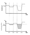
図2を参照してこれらの制御を具体的に説明する。この図の上の図は、車両要求出力Pv及びドライバ要求パワーの時間変化の一例を示している。なお、実線L1が車両要求出力Pvの時間変化を示し、実線L2がドライバ要求パワーの時間変化を示している。上述したように車両要求出力Pvは、バッテリ15を充電するために要求されるパワーをドライバ要求パワーに加算した値である。この図に示した例では、バッテリ15を充電する必要があるため、車両要求出力Pvがドライバ要求パワーより大きくなっている。なお、この図において車両要求出力Pvとドライバ要求パワーとの差が、バッテリ15を充電するために要求されるパワーである。この図の下の図は、エンジン11の出力パワーの時間変化の一例を示している。実線L3が上述したようにエンジン11を制御したときのエンジン11の出力パワーの時間変化を示している。なお、この図には、比較例として、車両要求出力Pvのパワーがエンジン11から出力されるようにエンジン11を制御した場合のエンジン11の出力パワーの時間変化を破線L4で示した。
These controls will be specifically described with reference to FIG. The upper part of this figure shows an example of the time change of the vehicle request output Pv and the driver request power. In addition, the continuous line L1 has shown the time change of the vehicle request | requirement output Pv, and the continuous line L2 has shown the time change of the driver request | requirement power. As described above, the vehicle request output Pv is a value obtained by adding the power required for charging the
図2に示した例では、時刻t1において車両要求出力Pvが始動閾値Psta以上になっている。そのため、エンジン11を始動している。また、走行モードをHVモードに切り替える。そして、車両要求出力Pvがエンジン11から出力されるようにエンジン11を制御する。その後、時刻t2において車両要求出力Pvが始動閾値Psta未満になると、出力下限値PLのパワーがエンジン11から出力されるようにエンジン11を制御する。その後、時刻t3において車両要求出力Pvが停止閾値Pstp以下になるとエンジン11を停止している。そして、走行モードをEVモードに切り替える。このように制御することにより、破線L4の比較例と比較して斜線を付した領域A1のパワーが余剰に発生する。上述したように、この余剰分のパワーは発電に用いられ、バッテリ15に充電される。
In the example shown in FIG. 2, the vehicle request output Pv is equal to or greater than the start threshold value Psta at time t1. Therefore, the
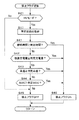
図3及び図4は、このような制御を実現するために車両制御装置30が実行する制御ルーチンを示している。図3は、車両制御装置30が車両1Aの走行モードを切り替えるために実行するモード切替制御ルーチンを示している。図4は、HVモードにおいて車両制御装置30がエンジン11を制御するために実行するエンジン制御ルーチンを示している。これらの制御ルーチンは、車両1Aの走行中に所定の周期で繰り返し実行される。
3 and 4 show a control routine executed by the
まず、図3の制御ルーチンを説明する。この制御ルーチンにおいて車両制御装置30は、まずステップS11で車両1Aの状態を取得する。車両1Aの状態としては、例えば車速、エンジン11の回転数、アクセル開度、及びバッテリ15の充電状態等が取得される。この他に、この処理ではアクセル開度に基づいてドライバ要求パワーを算出する。また、バッテリ15の充電状態に基づいてバッテリ15の充電が必要か否か判定し、充電が必要な場合には充電状態に応じてバッテリ15の充電に必要な要求パワーを算出する。なお、これらの要求パワーはいずれも周知の算出方法で算出すればよいため、詳細な説明を省略する。そして、これら算出した要求パワーから車両要求出力Pvを算出する。
First, the control routine of FIG. 3 will be described. In this control routine, the
次のステップS12において車両制御装置30は、車両要求出力Pvが始動閾値Psta以上か否か判定する。車両要求出力Pvが始動閾値Psta以上と判定した場合はステップS13に進み、車両制御装置30は出力下限値PLが設定済みであることを示す設定フラグがオンの状態か否か判定する。設定フラグがオンの状態であると判定した場合は今回の制御ルーチンを終了する。一方、設定フラグがオフの状態であると判定した場合はステップS14に進み、車両制御装置30は出力下限値PLを設定する。上述したように出力下限値PLには、車両要求出力Pvが始動閾値Psta以上になったときの始動閾値Pstaが設定される。また、この処理において、車両制御装置30は設定フラグをオンの状態に切り替える。続くステップS15において、車両制御装置30はエンジン11を始動する。次のステップS16において、車両制御装置30は車両1Aの走行モードをHVモードに切り替える。なお、既に走行モードがHVモードであった場合には、HVモードを維持する。その後、今回の制御ルーチンを終了する。
In the next step S12, the
一方、車両要求出力Pvが始動閾値Psta未満と判定した場合はステップS17に進み、車両制御装置30は車両要求出力Pvが停止閾値Pstp以下か否か判定する。車両要求出力Pvが停止閾値Pstpより大きいと判定した場合は、今回の制御ルーチンを終了する。一方、車両要求出力Pvが停止閾値Pstp以下と判定した場合はステップS18に進み、車両制御装置30は設定フラグがオフの状態か否か判定する。設定フラグがオフの状態であると判定した場合は今回の制御ルーチンを終了する。一方、設定フラグがオンの状態であると判定した場合はステップS19に進み、車両制御装置30はエンジン11を停止する。なお、既にエンジン11が停止していた場合はその状態を維持する。また、この処理において、車両制御装置30は設定フラグをオフの状態に切り替える。次のステップS20において車両制御装置30は車両1Aの走行モードをEVモードに切り替える。なお、既に走行モードがEVモードであった場合には、EVモードを維持する。その後、今回の制御ルーチンを終了する。
On the other hand, when it determines with vehicle request | requirement output Pv being less than start threshold value Psta, it progresses to step S17, and
次に図4の制御ルーチンについて説明する。なお、図4において図3と共通の部分には同一の符号を付して説明を省略する。この制御ルーチンにおいて車両制御装置30は、まずステップS21で車両1Aの走行モードがHVモードであるか否か判定する。走行モードがEVモードと判定した場合は、今回の制御ルーチンを終了する。一方、走行モードがHVモードと判定した場合はステップS11に進み、車両制御装置30は車両1Aの状態を取得する。次のステップS22において、車両制御装置30は要求エンジン出力Peを設定する。車両要求出力Pvに対してエンジン11の出力パワーが不足する場合には、エンジン11から出力可能なパワーの最大値が要求エンジン出力Peに設定される。一方、車両要求出力Pvをエンジン11から出力可能な場合には、車両要求出力Pvが要求エンジン出力Peに設定される。続くステップS23において車両制御装置30は、要求エンジン出力Peが出力下限値PLより大きいか否か判定する。要求エンジン出力Peが出力下限値PLより大きいと判定した場合はステップS24に進み、車両制御装置30はエンジン11から出力すべき目標出力Ptに要求エンジン出力Peを設定する。一方、要求エンジン出力Peが出力下限値PL以下と判定した場合はステップS25に進み、車両制御装置30は目標出力Ptに出力下限値PLを設定する。
Next, the control routine of FIG. 4 will be described. 4 that are the same as those in FIG. 3 are given the same reference numerals, and descriptions thereof are omitted. In this control routine, the
ステップS24又はステップS25にて目標出力Ptを設定した後はステップS26に進み、車両制御装置30はエンジン出力制御を実行する。このエンジン出力制御では、設定した目標出力Ptがエンジン11から出力されるようにエンジン11を制御する。次のステップS27において、車両制御装置30は発電制御を実行する。この発電制御では、目標出力Ptからドライバ要求パワーを減算したパワーが発電で消費されるように第1MG12の発電量を制御する。なお、目標出力Ptからドライバ要求パワーを減算したパワーがゼロ以下になる場合には、発電量をゼロにする。その後、今回の制御ルーチンを終了する。
After the target output Pt is set in step S24 or step S25, the process proceeds to step S26, and the
以上に説明したように、第1の形態では、HVモードにおいて要求エンジン出力Peが出力下限値PL以下の場合には目標出力Ptに出力下限値PLが設定される。すなわち、エンジン11は、出力下限値PL以上のパワーを出力するように制御される。そのため、出力が低く熱効率が悪くなる運転領域でエンジン11を運転することを抑制できる。これによりエンジン11の熱効率を向上させることができるので、燃費を向上させることができる。また、第1の形態では、要求エンジン出力Peが出力下限値PL以下の場合には目標出力Ptに出力下限値PLが設定されるので、運転者に与える違和感を抑制できる。
As described above, in the first embodiment, when the required engine output Pe is equal to or lower than the output lower limit PL in the HV mode, the output lower limit PL is set as the target output Pt. That is, the
図5及び図6を参照してこれらの作用効果について説明する。図5は、上述した図4のエンジン制御でエンジン11を制御した場合の車両要求出力Pvとエンジン11の出力パワーの時間変化の一例を示している。図6は、要求エンジン出力Peが出力下限値PL以下のときには予め設定した所定の嵩上げパワーPaddを要求エンジン出力Peに加算する制御(以下、比較例の制御と称することがある。)でエンジン11を制御した場合の車両要求出力Pvとエンジン11の出力パワーの時間変化の一例を示している。なお、図5及び図6における車両要求出力Pvの時間変化は同じである。すなわち、図5の上の図と図6の上の図とは同じである。図5及び図6で共通の部分には、同一の符号を付している。これらの図に示した例では、時刻t11〜t12の期間及び時刻t13〜t14の期間において運転者が車両1Aに減速を要求している。そのため、これらの期間において要求エンジン出力Peが出力下限値PL以下に低下している。
These functions and effects will be described with reference to FIGS. FIG. 5 shows an example of a time change of the vehicle request output Pv and the output power of the
図6に示すように、比較例の制御でエンジン11を制御した場合、要求エンジン出力Peが出力下限値PL以下になると所定の嵩上げパワーPaddが加算される。そのため、例えば時刻t11〜t12の期間のように、出力下限値PLと要求エンジン出力Peとの差が嵩上げパワーPaddより小さい場合には、エンジン出力パワーが減速前より大きくなる。そのため、運転者が減速を要求しているにも拘わらずエンジン11の回転数が増加したりエンジン音が大きくなったりする。したがって、運転者に違和感を与える。また、時刻t13〜t14の期間のように、出力下限値PLと要求エンジン出力Peとの差が嵩上げパワーPaddより大きい場合には、嵩上げパワーPaddを加算した後のエンジン出力パワーが出力下限値PLに達しない。そのため、熱効率が悪い運転領域でエンジン11を運転することになる。したがって、エンジン11の熱効率が低下する。
As shown in FIG. 6, when the
これに対して、第1の形態の制御でエンジン11を制御した場合には、図5に示すように、時刻t11〜t12の期間及び時刻t13〜t14の期間においてエンジン出力パワーが出力下限値PLになるようにエンジン11を制御する。そのため、時刻t11〜t12の期間においてはエンジン出力パワーが小さくなるので、運転者に与える違和感を抑制できる。そして、時刻t13〜t14の期間では、エンジン11の出力パワーが出力下限値PLになるので、熱効率が良い運転領域でエンジン11を運転できる。これによりエンジン11の熱効率を向上させることができるので、燃費を向上させることができる。
On the other hand, when the
なお、図1の車両1Aでは、第1MG12が本発明の発電機に相当する。図4の制御ルーチンを実行することにより、車両制御装置30が本発明の出力制御手段として機能する。
In the
(第2の形態)
次に図7〜図9を参照して本発明の第2の形態に係る制御装置を説明する。なお、この形態においても車両1Aについては図1が参照される。また、この形態においても車両制御装置30は図3のモード切替制御ルーチンを実行する。図7は、第2の形態において車両制御装置30が実行するエンジン制御ルーチンを示している。図7のルーチンでは、図4のステップS11とステップS22の間にステップS31が設けられている点が異なり、それ以外は図4と同じである。そのため、図7において図4と同一の処理には同一の符号を付して説明を省略する。
(Second form)
Next, a control device according to a second embodiment of the present invention will be described with reference to FIGS. In this embodiment as well, FIG. 1 is referred to for the
図7の制御ルーチンでは、ステップS22で要求エンジン出力Peを設定した後ステップS31に進み、車両制御装置30は要求エンジン出力Peが出力下限値PL以下であっても目標出力Ptに出力下限値PLを設定することを禁止する禁止フラグがオンの状態か否か判定する。この禁止フラグは、図8に示す禁止フラグ切替ルーチンにて設定される。禁止フラグがオフの状態であると判定した場合はステップS23に進み、以降は図4と同様に処理を進める。
In the control routine of FIG. 7, after setting the required engine output Pe in step S22, the process proceeds to step S31, and the
一方、禁止フラグがオンの状態であると判定した場合はステップS23をスキップしてステップS24に進み、以降は図4と同様に処理を進める。 On the other hand, if it is determined that the prohibition flag is in the on state, step S23 is skipped and the process proceeds to step S24. Thereafter, the process proceeds in the same manner as in FIG.
図8の禁止フラグ切替ルーチンについて説明する。このルーチンは車両1Aの走行中に所定の周期で繰り返し実行される。なお、このルーチンにおいて図3又は図4と同一の処理には同一の符号を付して説明を省略する。
The prohibition flag switching routine of FIG. 8 will be described. This routine is repeatedly executed at a predetermined cycle while the
このルーチンにおいて車両制御装置30は、まずステップS21で車両1Aの走行モードがHVモードか否か判定する。走行モードがEVモードと判定した場合は、ステップS11及びステップS41〜S44をスキップしてステップS45に進む。一方、走行モードがHVモードと判定した場合はステップS11に進み、車両制御装置30は車両1Aの状態を取得する。次のステップS41において車両制御装置30は、エンジン11を出力下限値PLの出力パワーで連続して運転した時間(以下、継続時間と称することがある。)が予め設定した所定の判定時間以上か否か判定する。継続時間は、例えば図7のステップS26の処理においてカウントすればよい。そして、例えば要求エンジン出力Peが下限値より大きくなった場合又はエンジン11を停止させた場合にそのカウントをゼロにリセットすればよい。なお、このようなカウント方法は周知の方法を用いればよいため、詳細な説明は省略する。判定時間は、例えばバッテリ15の仕様に応じて適宜に設定すればよい。周知のように、長時間連続してバッテリ15の充電を行うとバッテリ15の劣化を早める。そこで、判定時間には、例えばバッテリ15の劣化を抑制可能な時間が設定される。
In this routine, the
継続時間が判定時間未満と判定した場合はステップS42に進み、車両制御装置30は積算充電量が予め設定した所定の判定充電量以上か否か判定する。積算充電量は、車両要求出力Pvが始動閾値Psta以上になってからバッテリ15に充電された充電量の積算値である。この積算充電量は、例えば図7のステップS27にてバッテリ15に充電した充電量に基づいて算出すればよい。そして、例えばエンジン11を停止させた場合に積算充電量をゼロにリセットすればよい。なお、この積算充電量の算出方法は周知の方法を用いればよいため、詳細な説明は省略する。判定充電量は、例えばバッテリ15の仕様に応じて適宜に設定すればよい。周知のように、バッテリ15が充電過多になるとバッテリ15の劣化を早める。そこで、判定充電量には、例えばバッテリ15の劣化を抑制可能な積算充電量が設定される。
When it is determined that the duration time is less than the determination time, the process proceeds to step S42, and the
積算充電量が判定充電量未満と判定した場合はステップS43に進み、車両制御装置30は車速が予め設定した所定の判定車速以上か否か判定する。上述したように車両1Aでは、減速時に第2MG13にて回生発電を行う。周知のように車速が高くなるほど、減速時に回生発電で発生する電気エネルギの量が多くなる。そのため、バッテリ15が充電過多になるおそれがある。そこで、判定車速には、例えば回生発電時にバッテリ15の充電過多を回避可能な車速が設定される。なお、このような車速は、バッテリ15の容量などに応じて適宜に設定すればよい。
When it determines with integrated charge amount being less than determination charge amount, it progresses to step S43 and the
車速が判定車速未満と判定した場合はステップS44に進み、車両制御装置30はバッテリ15のSOCが予め設定した所定の判定SOC以上か否か判定する。バッテリ15のSOCが高すぎると減速時に回生発電で充電過多になるおそれがある。そこで、判定SOCには、例えば回生発電時にバッテリ15の充電過多を回避可能なSOCが設定される。なお、このようなSOCは、バッテリ15の容量などに応じて適宜に設定すればよい。
When it is determined that the vehicle speed is less than the determination vehicle speed, the process proceeds to step S44, and the
バッテリ15のSOCが判定SOC未満と判定した場合はステップS45に進み、車両制御装置30は禁止フラグをオフに切り替える。その後、今回のルーチンを終了する。
When it determines with SOC of the
一方、ステップS41にて継続時間が判定時間以上と判定した場合、ステップS42にて積算充電量が判定充電量以上と判定した場合、ステップS43にて車速が判定車速以上と判定した場合、又はステップS44にてバッテリ15のSOCが判定SOC以上と判定した場合はステップS46に進み、車両制御装置30は禁止フラグをオンの状態に切り替える。その後、今回のルーチンを終了する。
On the other hand, if it is determined in step S41 that the duration is equal to or greater than the determination time, if it is determined in step S42 that the integrated charge amount is equal to or greater than the determination charge amount, if it is determined in step S43 that the vehicle speed is equal to or greater than the determination vehicle speed, When it determines with SOC of the
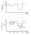
図9は、図7及び図8に示したルーチンでエンジン11を制御したときのバッテリ15のSOC、バッテリ15の入出力、エンジン11の出力パワー、及びエンジン11の熱効率の時間変化の一例を示している。なお、バッテリ15の入出力に関しては、正(+)がバッテリ15への充電(入力)を示し、負(−)がバッテリ15からの放電(出力)を示している。また、実線L11がこの入出力の時間変化を示し、実線L12がバッテリ15への入力の時間変化を示している。この図に示した例では、破線で囲んだ期間P11、P12においてバッテリ15のSOCが判定SOC以上になってエンジン11の出力パワーがほぼゼロになっている。また、破線で囲んだ期間P13においては、継続時間が判定時間以上になったり積算充電量が判定充電量以上になったりしてエンジン11の出力パワーが数回一時的にほぼゼロになっている。
FIG. 9 shows an example of changes over time in the SOC of the
以上に説明したように、この形態では、継続時間が判定時間以上になったり積算充電量が判定充電量以上になったりした場合には、要求エンジン出力Peが出力下限値PL以下であっても目標出力Ptに出力下限値PLを設定することを禁止する。そのため、バッテリ15の劣化を抑制できる。また、車速が判定車速以上になったりバッテリ15のSOCが判定SOC以上になったりした場合にも目標出力Ptに出力下限値PLを設定することを禁止するので、さらにバッテリ15の劣化を抑制できる。
As described above, in this embodiment, even when the requested engine output Pe is equal to or less than the output lower limit PL when the duration time is equal to or greater than the determination time or the accumulated charge amount is equal to or greater than the determination charge amount. Setting the output lower limit PL to the target output Pt is prohibited. Therefore, deterioration of the
なお、図8に示した例では、継続時間、積算充電量、車速、及びバッテリ15のSOCの全てを用いて目標出力Ptに出力下限値PLを設定することを禁止するか否か判定したが、この判定はこれらのうちの少なくとも1つを用いて行えばよい。すなわち、ステップS41のみを用いて禁止するか否か判定してもよいし、ステップS42のみを用いて禁止するか否か判定してもよい。さらに、これらのうちの2つ以上を適宜に組み合わせて禁止するか否か判定してもよい。
In the example illustrated in FIG. 8, it is determined whether to prohibit setting the output lower limit value PL to the target output Pt using all of the duration time, the accumulated charge amount, the vehicle speed, and the SOC of the
なお、図8のステップS41及び図7のステップS31を実行することにより、車両制御装置30が本発明の時間禁止手段として機能する。また、図8のステップS42及び図7のステップS31を実行することにより、車両制御装置30が本発明の充電量禁止手段として機能する。
In addition, by performing step S41 of FIG. 8 and step S31 of FIG. 7, the
本発明は、上述した各形態に限定されることなく、種々の形態にて実施することができる。例えば、本発明の制御装置が適用される車両は、図1に示した車両1Aに限定されない。例えば、図10に示したハイブリッド車両1Bに本発明を適用してもよい。なお、図10において図1と共通の部分には同一の符号を付して説明を省略する。この車両1Bは、エンジン11及び1つのモータ・ジェネレータ40を走行用動力源として備えている。この図に示すようにエンジン11の出力軸11aは、モータ・ジェネレータ40の出力軸40aと接続されている。そして、モータ・ジェネレータ40の出力軸40aは、変速機41の入力軸41aと接続されている。変速機41としては、例えば周知の自動変速機や無段変速機が設けられる。変速機41の出力軸41aは、デファレンシャル機構23と接続されている。この車両1Bでは、エンジン11で駆動輪2を駆動できる。また、エンジン11を停止させ、モータ・ジェネレータ40のみで駆動輪2を駆動できる。
This invention is not limited to each form mentioned above, It can implement with a various form. For example, the vehicle to which the control device of the present invention is applied is not limited to the
このような車両1Bにも上述した各形態の制御を適用することにより、熱効率が悪い運転領域でエンジン11が運転されることを抑制できる。そのため、エンジン11の熱効率を向上させることができる。したがって、燃費を向上させることができる。
By applying the control of each embodiment described above to such a
上述した各形態では、出力下限値PLに始動閾値Pstaを設定したが、出力下限値PLに設定される出力パワーはこの値に限定されない。例えば、出力下限値PLには、車両要求出力Pvが始動閾値Psta以上になったときの始動閾値Pstaに基づいて適宜の値を設定してよい。例えば、始動閾値Pstaより若干小さい出力パワーを設定してもよい。また、出力下限値PLには、エンジン11を熱効率が良い運転領域で運転可能なように停止閾値Pstpより大きい適宜の出力パワーを予め設定しておいてもよい。
In each form mentioned above, although starting threshold value Psta was set to output lower limit PL, the output power set to output lower limit PL is not limited to this value. For example, the output lower limit value PL may be set to an appropriate value based on the start threshold value Psta when the vehicle request output Pv becomes equal to or greater than the start threshold value Psta. For example, an output power slightly smaller than the start threshold value Psta may be set. Further, the output lower limit value PL may be set in advance with an appropriate output power that is larger than the stop threshold value Pstp so that the
上述した各形態では、車両要求出力Pvが始動閾値Psta未満の場合には、エンジン11の出力パワーを出力下限値PLに制御したが、この際のエンジン11の出力パワーはこの出力下限値PLに限定されない。例えば、エンジン11の出力パワーが出力下限値PLより若干大きい値になるようにエンジン11を制御してもよい。
In each embodiment described above, when the vehicle required output Pv is less than the start threshold value Psta, the output power of the
さらに、始動閾値Pstaが車速等に応じて変化する場合には、出力下限値PLも車速に応じて変化させてもよい。例えば、車速が速くなるほど始動閾値Pstaが大きくなる場合には、車両要求出力Pvが始動閾値Psta以上になってから車両要求出力Pvが停止閾値Pstp以下になるまでの間、車速が速くなるほど出力下限値PLを大きくなるように車速に応じて出力下限値PLを変化させてもよい。ただし、この場合であっても、出力下限値PLは、車両要求出力Pvが始動閾値Psta以上になったとき、すなわち走行モードをHVモードに切り替えたときの始動閾値Psta未満に変更しない。これにより、車両要求出力Pvが始動閾値Psta以上になってから車両要求出力Pvが停止閾値Pstp以下になるまでの間、エンジン11からは走行モードをHVモードに切り替えたときの始動閾値Psta以上の出力パワーが出力される。そのため、熱効率が悪い運転領域でエンジン11が運転されることを抑制できる。
Furthermore, when the starting threshold value Psta changes according to the vehicle speed or the like, the output lower limit value PL may also be changed according to the vehicle speed. For example, when the start threshold value Psta increases as the vehicle speed increases, the output lower limit is increased as the vehicle speed increases from when the vehicle request output Pv becomes equal to or greater than the start threshold value Psta until the vehicle request output Pv becomes equal to or less than the stop threshold value Pstp. The output lower limit value PL may be changed according to the vehicle speed so as to increase the value PL. However, even in this case, the output lower limit PL is not changed to be less than the start threshold Psta when the vehicle request output Pv is equal to or greater than the start threshold Psta, that is, when the travel mode is switched to the HV mode. Thus, from the time when the vehicle required output Pv becomes equal to or higher than the start threshold Psta to the time when the vehicle required output Pv becomes equal to or lower than the stop threshold Pstp, the
本発明が適用される車両の内燃機関は、火花点火式の内燃機関に限定されず、ディーゼル内燃機関であってもよい。上述した各形態では、動力分割機構としてシングルピニオン型の遊星歯車機構を用いたが、ダブルピニオン型の遊星歯車機構を動力分割機構として使用してもよい。 The internal combustion engine of the vehicle to which the present invention is applied is not limited to a spark ignition type internal combustion engine, and may be a diesel internal combustion engine. In each embodiment described above, a single pinion type planetary gear mechanism is used as the power split mechanism, but a double pinion type planetary gear mechanism may be used as the power split mechanism.
1A、1B ハイブリッド車両
11 内燃機関
11a 出力軸
12 第1モータ・ジェネレータ(発電機)
13 第2モータ・ジェネレータ
15 バッテリ
30 車両制御装置(出力制御手段、時間禁止手段、充電量禁止手段)
40 モータ・ジェネレータ
Pv 車両要求出力
Psta 始動閾値
Pstp 停止閾値
PL 出力下限値
1A,
13 Second motor /
40 Motor generator Pv Required vehicle output Psta Start threshold Pstp Stop threshold PL Output lower limit
Claims (5)
前記車両に要求されている出力パワーである車両要求出力が予め設定された所定の始動閾値以上になった場合に前記内燃機関を始動し、前記車両要求出力が前記始動閾値より小さい所定の停止閾値以下になった場合に前記内燃機関を停止させる制御装置において、
前記車両要求出力が前記始動閾値以上になってから前記車両要求出力が前記停止閾値以下になるまでの間、所定の出力下限値以上の出力パワーが前記内燃機関から出力されるように前記内燃機関を制御する出力制御手段を備え、
前記出力下限値には、前記停止閾値より大きい出力パワーが設定され、
前記出力制御手段は、前記車両要求出力が前記始動閾値以上になってから前記車両要求出力が前記停止閾値以下になるまでの間、前記車両要求出力が前記始動閾値未満であり、かつ前記内燃機関の出力パワーが前記出力下限値になるように前記内燃機関を制御する場合に、前記車両要求出力と前記出力下限値の差に相当する出力パワーが前記モータ・ジェネレータ又は前記発電機で発電に消費されてバッテリに充電されるように前記モータ・ジェネレータ又は前記発電機を制御し、
前記車両要求出力が前記始動閾値未満であり、かつ前記内燃機関から前記出力下限値以上の出力パワーが出力されるように前記内燃機関が連続して運転された時間が、予め設定された所定の判定時間以上になった場合には、前記出力制御手段による前記内燃機関の制御を禁止して前記車両要求出力で前記内燃機関が運転されるように前記内燃機関を制御する時間禁止手段をさらに備えている制御装置。 Applied to a hybrid vehicle comprising an internal combustion engine and a motor / generator as a motive power source for travel, wherein the motor / generator or generator is connected to the output shaft of the internal combustion engine so that power can be transmitted,
The internal combustion engine is started when a vehicle request output, which is an output power required for the vehicle, exceeds a predetermined start threshold value set in advance, and a predetermined stop threshold value where the vehicle request output is smaller than the start threshold value In the control device for stopping the internal combustion engine when
The internal combustion engine is configured such that output power equal to or higher than a predetermined output lower limit value is output from the internal combustion engine until the vehicle required output becomes equal to or lower than the stop threshold after the vehicle required output becomes equal to or higher than the start threshold. Output control means for controlling
The output lower limit value is set to an output power greater than the stop threshold ,
The output control means is configured such that the vehicle request output is less than the start threshold and the internal combustion engine from when the vehicle request output becomes equal to or greater than the start threshold until the vehicle request output becomes equal to or less than the stop threshold. When the internal combustion engine is controlled so that the output power of the engine becomes the output lower limit value, the output power corresponding to the difference between the vehicle required output and the output lower limit value is consumed for power generation by the motor generator or the generator. And controlling the motor generator or the generator so that the battery is charged,
The time during which the internal combustion engine is continuously operated so that the vehicle required output is less than the start threshold and the output power equal to or higher than the output lower limit value is output from the internal combustion engine is a predetermined value set in advance. And a time prohibiting unit that controls the internal combustion engine so that the internal combustion engine is operated with the vehicle required output by prohibiting the control of the internal combustion engine by the output control unit when the determination time is exceeded. Control unit.
Priority Applications (5)
| Application Number | Priority Date | Filing Date | Title |
|---|---|---|---|
| JP2014089359A JP5924366B2 (en) | 2014-04-23 | 2014-04-23 | Control device for hybrid vehicle |
| DE102015106028.0A DE102015106028B4 (en) | 2014-04-23 | 2015-04-20 | Control system of a hybrid vehicle |
| KR1020150055185A KR101660636B1 (en) | 2014-04-23 | 2015-04-20 | Control system of hybrid vehicle |
| US14/692,208 US9522670B2 (en) | 2014-04-23 | 2015-04-21 | Control system of hybrid vehicle |
| CN201510195124.4A CN105035077B (en) | 2014-04-23 | 2015-04-23 | The control system of motor vehicle driven by mixed power |
Applications Claiming Priority (1)
| Application Number | Priority Date | Filing Date | Title |
|---|---|---|---|
| JP2014089359A JP5924366B2 (en) | 2014-04-23 | 2014-04-23 | Control device for hybrid vehicle |
Publications (2)
| Publication Number | Publication Date |
|---|---|
| JP2015205673A JP2015205673A (en) | 2015-11-19 |
| JP5924366B2 true JP5924366B2 (en) | 2016-05-25 |
Family
ID=54261894
Family Applications (1)
| Application Number | Title | Priority Date | Filing Date |
|---|---|---|---|
| JP2014089359A Expired - Fee Related JP5924366B2 (en) | 2014-04-23 | 2014-04-23 | Control device for hybrid vehicle |
Country Status (5)
| Country | Link |
|---|---|
| US (1) | US9522670B2 (en) |
| JP (1) | JP5924366B2 (en) |
| KR (1) | KR101660636B1 (en) |
| CN (1) | CN105035077B (en) |
| DE (1) | DE102015106028B4 (en) |
Families Citing this family (8)
| Publication number | Priority date | Publication date | Assignee | Title |
|---|---|---|---|---|
| DE102015223588A1 (en) * | 2015-11-27 | 2017-06-01 | Bayerische Motoren Werke Aktiengesellschaft | Control system with at least one electronic control unit for controlling an internal combustion engine in a hybrid vehicle |
| DE102017218855A1 (en) | 2017-10-23 | 2019-04-25 | Audi Ag | Dynamically determined auxiliary power for an internal combustion engine of a hybrid vehicle |
| JP2019081413A (en) * | 2017-10-30 | 2019-05-30 | 本田技研工業株式会社 | Vehicle control system, vehicle control method, and program |
| CN112412638B (en) * | 2019-08-23 | 2022-02-08 | 比亚迪股份有限公司 | Vehicle, and control method and control device thereof |
| US11702059B2 (en) | 2020-07-22 | 2023-07-18 | Cummins Inc. | Systems and methods for online power management for hybrid powertrains |
| CN111959485B (en) * | 2020-09-17 | 2024-04-05 | 山东临工工程机械有限公司 | Power control method and device for hybrid excavator |
| DE102020128730B4 (en) * | 2020-11-02 | 2024-03-14 | Audi Aktiengesellschaft | Method for operating a motor vehicle and corresponding motor vehicle |
| EP4249302A1 (en) * | 2022-03-21 | 2023-09-27 | Iveco S.p.A. | System and method of configuration of a control processing unit of a hybrid transmission |
Family Cites Families (10)
| Publication number | Priority date | Publication date | Assignee | Title |
|---|---|---|---|---|
| JP3812134B2 (en) | 1998-04-08 | 2006-08-23 | トヨタ自動車株式会社 | Charge control method for hybrid vehicle |
| BR9913684A (en) | 1998-09-14 | 2001-11-27 | Paice Corp | Hybrid vehicles |
| JP3945370B2 (en) | 2002-10-25 | 2007-07-18 | トヨタ自動車株式会社 | Car |
| JP4967737B2 (en) | 2007-03-22 | 2012-07-04 | トヨタ自動車株式会社 | Control device for internal combustion engine |
| JP5556280B2 (en) | 2010-03-18 | 2014-07-23 | アイシン精機株式会社 | Control device for hybrid vehicle |
| JP2011240757A (en) * | 2010-05-17 | 2011-12-01 | Toyota Motor Corp | Hybrid vehicle |
| JP2011255824A (en) | 2010-06-10 | 2011-12-22 | Mitsubishi Motors Corp | Device for control of hybrid vehicle |
| JP2012106672A (en) * | 2010-11-18 | 2012-06-07 | Toyota Motor Corp | Hybrid vehicle |
| JP5703716B2 (en) | 2010-11-26 | 2015-04-22 | トヨタ自動車株式会社 | Hybrid car |
| JP2013154666A (en) | 2012-01-26 | 2013-08-15 | Nissan Motor Co Ltd | Hybrid vehicle control apparatus |
-
2014
- 2014-04-23 JP JP2014089359A patent/JP5924366B2/en not_active Expired - Fee Related
-
2015
- 2015-04-20 DE DE102015106028.0A patent/DE102015106028B4/en not_active Expired - Fee Related
- 2015-04-20 KR KR1020150055185A patent/KR101660636B1/en active IP Right Grant
- 2015-04-21 US US14/692,208 patent/US9522670B2/en active Active
- 2015-04-23 CN CN201510195124.4A patent/CN105035077B/en active Active
Also Published As
| Publication number | Publication date |
|---|---|
| KR101660636B1 (en) | 2016-09-27 |
| US9522670B2 (en) | 2016-12-20 |
| CN105035077A (en) | 2015-11-11 |
| CN105035077B (en) | 2017-10-20 |
| US20150307080A1 (en) | 2015-10-29 |
| KR20150122591A (en) | 2015-11-02 |
| JP2015205673A (en) | 2015-11-19 |
| DE102015106028A1 (en) | 2015-10-29 |
| DE102015106028B4 (en) | 2019-05-16 |
Similar Documents
| Publication | Publication Date | Title |
|---|---|---|
| JP5924366B2 (en) | Control device for hybrid vehicle | |
| KR101742397B1 (en) | Hybrid vehicle | |
| US9884619B2 (en) | Selective electric mode for electric vehicle | |
| JP6156303B2 (en) | Hybrid vehicle | |
| JP6179504B2 (en) | Hybrid vehicle | |
| US9868448B2 (en) | Hybrid vehicle | |
| JP5825287B2 (en) | Hybrid vehicle | |
| US9868434B2 (en) | Vehicle and control method for vehicle | |
| JP2007185986A (en) | Controller for vehicle | |
| US9050902B2 (en) | Hybrid vehicle and method for controlling hybrid vehicle | |
| JP2015154534A (en) | storage battery control device | |
| US9682695B2 (en) | Vehicle control apparatus and vehicle control method | |
| JP6149814B2 (en) | Hybrid vehicle | |
| RU2625401C2 (en) | Vehicle control device and vehicle control method | |
| JP6213498B2 (en) | Hybrid vehicle | |
| JP2013006430A (en) | Hybrid vehicle and control method therefor | |
| JP6361299B2 (en) | Hybrid vehicle | |
| US11059374B2 (en) | Hybrid vehicle control apparatus and hybrid vehicle | |
| JP5974796B2 (en) | Hybrid vehicle and control method of hybrid vehicle | |
| JP2015009746A (en) | Control device for hybrid vehicle | |
| JP2019111969A (en) | Hybrid automobile | |
| JP2021095034A (en) | Electric vehicle | |
| JP2016010981A (en) | Hybrid-vehicular control apparatus | |
| JP2015168385A (en) | hybrid vehicle |
Legal Events
| Date | Code | Title | Description |
|---|---|---|---|
| A131 | Notification of reasons for refusal |
Free format text: JAPANESE INTERMEDIATE CODE: A131 Effective date: 20151104 |
|
| A521 | Request for written amendment filed |
Free format text: JAPANESE INTERMEDIATE CODE: A523 Effective date: 20151217 |
|
| TRDD | Decision of grant or rejection written | ||
| A01 | Written decision to grant a patent or to grant a registration (utility model) |
Free format text: JAPANESE INTERMEDIATE CODE: A01 Effective date: 20160322 |
|
| A61 | First payment of annual fees (during grant procedure) |
Free format text: JAPANESE INTERMEDIATE CODE: A61 Effective date: 20160404 |
|
| R151 | Written notification of patent or utility model registration |
Ref document number: 5924366 Country of ref document: JP Free format text: JAPANESE INTERMEDIATE CODE: R151 |
|
| LAPS | Cancellation because of no payment of annual fees |