EP4249302A1 - System and method of configuration of a control processing unit of a hybrid transmission - Google Patents
System and method of configuration of a control processing unit of a hybrid transmission Download PDFInfo
- Publication number
- EP4249302A1 EP4249302A1 EP23161313.4A EP23161313A EP4249302A1 EP 4249302 A1 EP4249302 A1 EP 4249302A1 EP 23161313 A EP23161313 A EP 23161313A EP 4249302 A1 EP4249302 A1 EP 4249302A1
- Authority
- EP
- European Patent Office
- Prior art keywords
- task
- transmission
- execution
- microprocessor
- sequence
- Prior art date
- Legal status (The legal status is an assumption and is not a legal conclusion. Google has not performed a legal analysis and makes no representation as to the accuracy of the status listed.)
- Pending
Links
- 230000005540 biological transmission Effects 0.000 title claims description 47
- 238000012545 processing Methods 0.000 title claims description 20
- 238000000034 method Methods 0.000 title claims description 11
- 230000015654 memory Effects 0.000 claims abstract description 20
- 230000007704 transition Effects 0.000 claims description 17
- 238000002485 combustion reaction Methods 0.000 claims description 16
- 238000004590 computer program Methods 0.000 claims description 3
- 238000004088 simulation Methods 0.000 claims description 2
- 230000003068 static effect Effects 0.000 claims description 2
- 230000008859 change Effects 0.000 description 9
- 230000004913 activation Effects 0.000 description 5
- 238000013461 design Methods 0.000 description 4
- 238000010586 diagram Methods 0.000 description 4
- 230000006870 function Effects 0.000 description 4
- 230000006399 behavior Effects 0.000 description 3
- 238000002360 preparation method Methods 0.000 description 2
- 230000001133 acceleration Effects 0.000 description 1
- 238000004364 calculation method Methods 0.000 description 1
- 230000001419 dependent effect Effects 0.000 description 1
- 238000004519 manufacturing process Methods 0.000 description 1
- 238000012544 monitoring process Methods 0.000 description 1
- 238000012360 testing method Methods 0.000 description 1
- 238000013519 translation Methods 0.000 description 1
Images


Classifications
-
- B—PERFORMING OPERATIONS; TRANSPORTING
- B60—VEHICLES IN GENERAL
- B60W—CONJOINT CONTROL OF VEHICLE SUB-UNITS OF DIFFERENT TYPE OR DIFFERENT FUNCTION; CONTROL SYSTEMS SPECIALLY ADAPTED FOR HYBRID VEHICLES; ROAD VEHICLE DRIVE CONTROL SYSTEMS FOR PURPOSES NOT RELATED TO THE CONTROL OF A PARTICULAR SUB-UNIT
- B60W10/00—Conjoint control of vehicle sub-units of different type or different function
- B60W10/04—Conjoint control of vehicle sub-units of different type or different function including control of propulsion units
- B60W10/06—Conjoint control of vehicle sub-units of different type or different function including control of propulsion units including control of combustion engines
-
- B—PERFORMING OPERATIONS; TRANSPORTING
- B60—VEHICLES IN GENERAL
- B60K—ARRANGEMENT OR MOUNTING OF PROPULSION UNITS OR OF TRANSMISSIONS IN VEHICLES; ARRANGEMENT OR MOUNTING OF PLURAL DIVERSE PRIME-MOVERS IN VEHICLES; AUXILIARY DRIVES FOR VEHICLES; INSTRUMENTATION OR DASHBOARDS FOR VEHICLES; ARRANGEMENTS IN CONNECTION WITH COOLING, AIR INTAKE, GAS EXHAUST OR FUEL SUPPLY OF PROPULSION UNITS IN VEHICLES
- B60K6/00—Arrangement or mounting of plural diverse prime-movers for mutual or common propulsion, e.g. hybrid propulsion systems comprising electric motors and internal combustion engines ; Control systems therefor, i.e. systems controlling two or more prime movers, or controlling one of these prime movers and any of the transmission, drive or drive units Informative references: mechanical gearings with secondary electric drive F16H3/72; arrangements for handling mechanical energy structurally associated with the dynamo-electric machine H02K7/00; machines comprising structurally interrelated motor and generator parts H02K51/00; dynamo-electric machines not otherwise provided for in H02K see H02K99/00
- B60K6/20—Arrangement or mounting of plural diverse prime-movers for mutual or common propulsion, e.g. hybrid propulsion systems comprising electric motors and internal combustion engines ; Control systems therefor, i.e. systems controlling two or more prime movers, or controlling one of these prime movers and any of the transmission, drive or drive units Informative references: mechanical gearings with secondary electric drive F16H3/72; arrangements for handling mechanical energy structurally associated with the dynamo-electric machine H02K7/00; machines comprising structurally interrelated motor and generator parts H02K51/00; dynamo-electric machines not otherwise provided for in H02K see H02K99/00 the prime-movers consisting of electric motors and internal combustion engines, e.g. HEVs
- B60K6/42—Arrangement or mounting of plural diverse prime-movers for mutual or common propulsion, e.g. hybrid propulsion systems comprising electric motors and internal combustion engines ; Control systems therefor, i.e. systems controlling two or more prime movers, or controlling one of these prime movers and any of the transmission, drive or drive units Informative references: mechanical gearings with secondary electric drive F16H3/72; arrangements for handling mechanical energy structurally associated with the dynamo-electric machine H02K7/00; machines comprising structurally interrelated motor and generator parts H02K51/00; dynamo-electric machines not otherwise provided for in H02K see H02K99/00 the prime-movers consisting of electric motors and internal combustion engines, e.g. HEVs characterised by the architecture of the hybrid electric vehicle
- B60K6/44—Series-parallel type
-
- B—PERFORMING OPERATIONS; TRANSPORTING
- B60—VEHICLES IN GENERAL
- B60W—CONJOINT CONTROL OF VEHICLE SUB-UNITS OF DIFFERENT TYPE OR DIFFERENT FUNCTION; CONTROL SYSTEMS SPECIALLY ADAPTED FOR HYBRID VEHICLES; ROAD VEHICLE DRIVE CONTROL SYSTEMS FOR PURPOSES NOT RELATED TO THE CONTROL OF A PARTICULAR SUB-UNIT
- B60W10/00—Conjoint control of vehicle sub-units of different type or different function
- B60W10/04—Conjoint control of vehicle sub-units of different type or different function including control of propulsion units
- B60W10/08—Conjoint control of vehicle sub-units of different type or different function including control of propulsion units including control of electric propulsion units, e.g. motors or generators
-
- B—PERFORMING OPERATIONS; TRANSPORTING
- B60—VEHICLES IN GENERAL
- B60W—CONJOINT CONTROL OF VEHICLE SUB-UNITS OF DIFFERENT TYPE OR DIFFERENT FUNCTION; CONTROL SYSTEMS SPECIALLY ADAPTED FOR HYBRID VEHICLES; ROAD VEHICLE DRIVE CONTROL SYSTEMS FOR PURPOSES NOT RELATED TO THE CONTROL OF A PARTICULAR SUB-UNIT
- B60W20/00—Control systems specially adapted for hybrid vehicles
- B60W20/10—Controlling the power contribution of each of the prime movers to meet required power demand
-
- B—PERFORMING OPERATIONS; TRANSPORTING
- B60—VEHICLES IN GENERAL
- B60W—CONJOINT CONTROL OF VEHICLE SUB-UNITS OF DIFFERENT TYPE OR DIFFERENT FUNCTION; CONTROL SYSTEMS SPECIALLY ADAPTED FOR HYBRID VEHICLES; ROAD VEHICLE DRIVE CONTROL SYSTEMS FOR PURPOSES NOT RELATED TO THE CONTROL OF A PARTICULAR SUB-UNIT
- B60W20/00—Control systems specially adapted for hybrid vehicles
- B60W20/20—Control strategies involving selection of hybrid configuration, e.g. selection between series or parallel configuration
-
- Y—GENERAL TAGGING OF NEW TECHNOLOGICAL DEVELOPMENTS; GENERAL TAGGING OF CROSS-SECTIONAL TECHNOLOGIES SPANNING OVER SEVERAL SECTIONS OF THE IPC; TECHNICAL SUBJECTS COVERED BY FORMER USPC CROSS-REFERENCE ART COLLECTIONS [XRACs] AND DIGESTS
- Y02—TECHNOLOGIES OR APPLICATIONS FOR MITIGATION OR ADAPTATION AGAINST CLIMATE CHANGE
- Y02T—CLIMATE CHANGE MITIGATION TECHNOLOGIES RELATED TO TRANSPORTATION
- Y02T10/00—Road transport of goods or passengers
- Y02T10/60—Other road transportation technologies with climate change mitigation effect
- Y02T10/62—Hybrid vehicles
Definitions
- the present invention relates to the field of methods for configuring a processing unit of a hybrid transmission.
- the "Prius" propulsion system there is a thermal engine and two electric motor generators arranged to cooperate in the propulsion of the vehicle and/or in recharging the vehicle batteries.
- the "Prius" scheme can provide multiple operation modes.
- the control unit for each variation of the transmission configuration, must verify the correct execution of a sequence of operations and inhibit a further variation of the configuration when the execution of the sequence of a previous variation is not completed.
- Events may also occur that prevent a configuration change from being completed.
- the behaviour of the processing unit is defined through a capabilities document containing each sequence of operations and determined through the production of a deterministic code which is subsequently loaded into the processing unit.
- the deterministic code proposes the finite state machines necessary to manage the transmission transitions between different configurations (e.g. from full electric with one engine to parallel hybrid with the others).
- the subject of the present invention is to present a system and method for configuring a control processing unit of a hybrid transmission.
- the basic idea of the present invention is to generate software executed on the processing unit, which simulates the operation of a microprocessor circuit architecture suitably programmed for the control of the hybrid transmission.
- the operation of programming the processing unit requires, as described below, the preparation of a spreadsheet representing the program executed by the simulated microprocessor.
- a processing unit programming change boils down to a quick spreadsheet change.
- control software which is loaded into the hardware processing unit forms a "soft processor", i.e. a virtual processor characterized by a memory containing the sequence of operations necessary for each transmission transition.
- a "soft processor” i.e. a virtual processor characterized by a memory containing the sequence of operations necessary for each transmission transition.
- the soft processor it is sufficient to change the memory contents and not the processor model.
- the programming operations of the hybrid transmission control processing unit do not involve the creation of deterministic code, but only the preparation of a spreadsheet.
- the transmission control unit is not configured to simply perform operations, but is configured to simulate a software microprocessor that performs a sequence of operations loaded into the virtual memory of the software processor.
- Fig. 1 shows the representative model-base design diagram of the virtual or software microprocessor.
- model-based diagrams are widely known to the person skilled in the art mainly thanks to the Simulink ® simulation software environment of Matlab ® .
- model-base design programming is entirely optional. What matters is to simulate a microprocessor circuit configured to receive the table described below as input.
- the diagram has as inputs a manual input, which can be, for example, made by means of a selector placed on the dashboard of the vehicle or an automatic decision-making system, for example, a processing unit or another function SW performed on the same control processing unit implementing the present invention, which for example is optimized to decide the operating mode of the transmission to reduce consumption or to maximize the driving torque, or to recharge the propulsion batteries and which therefore establishes the most suitable transmission configuration according to certain operating parameters and operating conditions of the vehicle.
- a manual input can be, for example, made by means of a selector placed on the dashboard of the vehicle or an automatic decision-making system, for example, a processing unit or another function SW performed on the same control processing unit implementing the present invention, which for example is optimized to decide the operating mode of the transmission to reduce consumption or to maximize the driving torque, or to recharge the propulsion batteries and which therefore establishes the most suitable transmission configuration according to certain operating parameters and operating conditions of the vehicle.
- the ways in which the calculation unit or the software module determines the optimal operating configuration of the transmission are not the object of the present invention and can be any.
- Selector S1 is arranged so as to give priority to the manual selector.
- Selector S2 is arranged in cascade to selector S1. This has as its first input the output of selector S1 and the output of a block called "Interrupt Handler”.
- the Interrupt Handler is a component or module arranged to monitor the correct execution of state transitions and to interrupt them under certain circumstances. This module is described in detail below.
- the Interrupt Handler takes precedence over any command received from the S1 selector.
- the "Lookup Table Memory” block represents the static and modifiable memory of the microprocessor. It is arranged immediately downstream of the selector S2. Each location or memory cell contains the identifiers of the task to be performed, operating codes, for passing from the current transmission configuration to a new configuration.
- it is at least a look up table arranged to indicate the sequence of operations to be performed to pass from one state to another state.
- This block is a software module or component placed downstream of the look up table and is optional. It translates the identifiers or symbols contained in the look up table into corresponding operations indicated below as TASK n.1,..., TASK n.#. The translation of the identifiers can be performed directly in the look up table by means of a more complex memory structure, for example based on pointers, and known to the person skilled in the art.
- the block "SCAN LOGIC” represents a software component or module that reads the so-called “opcodes”, i.e. the outputs of the lookup table memory to generate the start triggers for the management tasks of the transmission hardware components, such as, for example, the actuators of the clutches to engage/disengage the propulsion motors.
- the SCAN LOGIC block "informs" the "REGISTER LOGIC” block.
- This latter block has a first input coinciding with the second selector S2, a second input coinciding with the output of the "SCAN LOGIC” block and an output connected to the Lookup Table Memory.
- the Register Logic block is in parallel with the Look up table.
- This block acts as a register, to update the current state of the transmission operating configuration when all transition operations have been completed.
- the input of this block is the next state, indicated by the second selector S2, and the output is the current state which represents one of the possible configurations of the transmission.
- this block has a first output connected to the second selector S2 to "override" the requests arriving from the first selector S1; a second output connected to a third selector S3 arranged between the output of the Lookup table memory and the Scan Logic and inputs connected to a hardware/software interface capable of monitoring the execution of operations and other signals such as, for example,
- This block is configured to override commands that arrive to the lookup table memory and the SCAN LOGIC block, when a stop condition occurs that impedes a transition between two operating conditions from executing or impedes its complete execution.
- Such a stop condition can consist of
- the interrupt handler interrupts the flow of commands from selector S1 to SCAN LOGIC, forcing a return to the previously set operating configuration.
- An example of a variation in the operating conditions of the vehicle may consist, for example, in a sudden variation of the resistant torque, for example due to an ascent or descent.
- An example of a change in vehicle control may consist of a sudden change in vehicle speed, for example due to sudden braking or sudden acceleration.
- the described scheme simulates the behavior of a microprocessor in which the (re)programmable portion is only the look up table memory which is described in detail below by means of table 1:
- the first column shows the current configurations:
- the first row shows the "new" configurations:
- the other cells of the table include a sequence of identifiers separated by a separator, for example a comma.
- a separator for example a comma.
- Each identifier corresponds to an operation to be performed and the order of the identifiers corresponds to the ordered sequence of operations to be performed.
- Table 2 below shows an example of identifier translator: Operation ID Operation to be performed 21 Switching on the propulsion inverter 10 Closing of the clutch of the electric motor 73 Activation of the traction control as a function of the position of the accelerator pedal 22 Turning on the internal combustion engine 2 Synchronization of the revolutions of the internal combustion engine with the rotational speed of the transmission gearbox 3 Closing of the clutch of the internal combustion engine 69 Distributing the torque between the electric motor and the internal combustion engine 100 Cancelling the torque delivered by the electric motor 121 Opening the electric motor clutch 145 Turning off the propulsion inverter 150 Putting the internal combustion engine to idle 155 Opening the internal combustion engine clutch 160 Turning off the internal combustion engine
- identifiers can vary according to the hardware configuration of the transmission and the multiple configuration possibilities.
- This indication means that there are no identifiers, as the transition from the current configuration to the new configuration is not possible or is not available.
- the present invention can advantageously be implemented through a computer program comprising coding means for carrying out one or more steps of the method, when this program is executed on a computer. Therefore it is understood that the scope of protection extends to said computer program and also to computer-readable means comprising a recorded message, said computer-readable means comprising program coding means for carrying out one or more steps of the method, when said program is run on a computer.
Abstract
Metodo di configurazione di un'unità di elaborazione di controllo di una trasmissione ibrida comprendente un motore a combustione interna, almeno un motore elettrico di propulsione e mezzi per gestire la connessione selettiva del motore a combustione interna e/o del motore elettrico alia trasmissione, in cui l'unità di elaborazione è configurata per simulare un microprocessore (CPU) comprendente una memoria (Lookup Table Memory) in cui è memorizzata una tabella (Tab 1) delle transizioni, in cui in ciascuna cella è indicata una sequenza di identificativi, ciascun identificativo indicando una operazione (Task) da eseguire.
Description
- The present invention relates to the field of methods for configuring a processing unit of a hybrid transmission.
- In hybrid vehicles, there are several drive units. For example, in the "Prius" propulsion system there is a thermal engine and two electric motor generators arranged to cooperate in the propulsion of the vehicle and/or in recharging the vehicle batteries.
- According to some documents released, the "Prius" scheme can provide multiple operation modes.
- The control unit, for each variation of the transmission configuration, must verify the correct execution of a sequence of operations and inhibit a further variation of the configuration when the execution of the sequence of a previous variation is not completed.
- Events may also occur that prevent a configuration change from being completed. One can consider, for example, the activation of the internal combustion engine while the driver is forced to brake suddenly, bringing the vehicle suddenly to a speed lower than that of activation of the internal combustion engine.
- Currently, the behaviour of the processing unit is defined through a capabilities document containing each sequence of operations and determined through the production of a deterministic code which is subsequently loaded into the processing unit.
- The deterministic code proposes the finite state machines necessary to manage the transmission transitions between different configurations (e.g. from full electric with one engine to parallel hybrid with the others).
- However, if a problem is encountered during the test drive or if the functionality document is modified, for example by changing the possible transitions, it becomes necessary to modify the deterministic code with an enormous consumption of time.
- In addition, the growing number of components that define the transmission greatly complicates the programming of the control unit that oversees the transmission. In fact, where it is necessary to monitor engagements, clutches, relative speeds between gears and applied torques, etc., it is desirable to find a simpler and faster way to program a processing unit that supervises the functions of a hybrid transmission.
- Unless specifically excluded in the detailed description that follows, what is described in this chapter is to be considered as an integral part of the detailed description.
- The subject of the present invention is to present a system and method for configuring a control processing unit of a hybrid transmission.
- The basic idea of the present invention is to generate software executed on the processing unit, which simulates the operation of a microprocessor circuit architecture suitably programmed for the control of the hybrid transmission.
- Advantageously, the operation of programming the processing unit requires, as described below, the preparation of a spreadsheet representing the program executed by the simulated microprocessor. Thus, a processing unit programming change boils down to a quick spreadsheet change.
- In other words, it is not necessary to directly design the finite state machines necessary to manage the transitions of the transmission between different configurations (e.g. from full electric with one motor to hybrid parallel with the others) but it is sufficient to simulate a microprocessor. Advantageously, the control software which is loaded into the hardware processing unit forms a "soft processor", i.e. a virtual processor characterized by a memory containing the sequence of operations necessary for each transmission transition. However, to change the behavior of the soft processor, it is sufficient to change the memory contents and not the processor model.
- In other words, the programming operations of the hybrid transmission control processing unit do not involve the creation of deterministic code, but only the preparation of a spreadsheet.
- From a hardware point of view, the transmission control unit is not configured to simply perform operations, but is configured to simulate a software microprocessor that performs a sequence of operations loaded into the virtual memory of the software processor.
- The dependent claims describe preferred variants of the invention, forming an integral part of the present description.
- Further objects and advantages of the present invention will become clear from the detailed description that follows of an embodiment of the same (and of its variants) and from the annexed drawings given for purely explanatory and non-limiting purposes, in which:
-
Fig. 1 shows a model-base design simulation diagram of the control processing unit of a hybrid transmission; -
Fig. 2 shows an example of a hybrid transmission of the known art whose control unit is programmed by means of the present invention. - The same reference numbers and letters in the figures identify the same elements or components or functions.
- It should also be noted that the terms "first", "second", "third", "superior", "inferior" and the like may be used herein to distinguish various items. These terms do not imply a spatial, sequential, or hierarchical order for the modified items unless specifically indicated or inferred from the text.
- The elements and features illustrated in the various preferred embodiments, including the drawings, can be combined with each other without however departing from the scope of protection of the present application as described below.
-
Fig. 1 shows the representative model-base design diagram of the virtual or software microprocessor. - The model-based diagrams are widely known to the person skilled in the art mainly thanks to the Simulink® simulation software environment of Matlab®.
- However, using model-base design programming is entirely optional. What matters is to simulate a microprocessor circuit configured to receive the table described below as input.
- The diagram has as inputs a manual input, which can be, for example, made by means of a selector placed on the dashboard of the vehicle or an automatic decision-making system, for example, a processing unit or another function SW performed on the same control processing unit implementing the present invention, which for example is optimized to decide the operating mode of the transmission to reduce consumption or to maximize the driving torque, or to recharge the propulsion batteries and which therefore establishes the most suitable transmission configuration according to certain operating parameters and operating conditions of the vehicle.
- The ways in which the calculation unit or the software module determines the optimal operating configuration of the transmission are not the object of the present invention and can be any.
- Selector S1 is arranged so as to give priority to the manual selector.
- Selector S2 is arranged in cascade to selector S1. This has as its first input the output of selector S1 and the output of a block called "Interrupt Handler".
- The Interrupt Handler is a component or module arranged to monitor the correct execution of state transitions and to interrupt them under certain circumstances. This module is described in detail below.
- As the manual selector takes precedence over the automatic decision making system, the Interrupt Handler takes precedence over any command received from the S1 selector. The "Lookup Table Memory" block represents the static and modifiable memory of the microprocessor. It is arranged immediately downstream of the selector S2. Each location or memory cell contains the identifiers of the task to be performed, operating codes, for passing from the current transmission configuration to a new configuration.
- In other words, it is at least a look up table arranged to indicate the sequence of operations to be performed to pass from one state to another state.
- An additional block "INDEXED MEMORY LOCATION WITH THE OPCONDES" is shown. This block is a software module or component placed downstream of the look up table and is optional. It translates the identifiers or symbols contained in the look up table into corresponding operations indicated below as TASK n.1,..., TASK n.#. The translation of the identifiers can be performed directly in the look up table by means of a more complex memory structure, for example based on pointers, and known to the person skilled in the art.
- The block "SCAN LOGIC" represents a software component or module that reads the so-called "opcodes", i.e. the outputs of the lookup table memory to generate the start triggers for the management tasks of the transmission hardware components, such as, for example, the actuators of the clutches to engage/disengage the propulsion motors.
- The "SCAN LOGIC" block, for each task in the sequence
- Commands the start of the execution of the task,
- Waits for its execution and after verifying its correct execution,
- Marks the task as done.
- Whenever a transition from one operating configuration to another is judged as concluded, the SCAN LOGIC block "informs" the "REGISTER LOGIC" block. This latter block has a first input coinciding with the second selector S2, a second input coinciding with the output of the "SCAN LOGIC" block and an output connected to the Lookup Table Memory. In other words, the Register Logic block is in parallel with the Look up table.
- It acts as a register, to update the current state of the transmission operating configuration when all transition operations have been completed. The input of this block is the next state, indicated by the second selector S2, and the output is the current state which represents one of the possible configurations of the transmission.
- In other words, when the selector S2 supplies a new configuration to the lookup table memory, the transition must necessarily be selected on the basis of the current operating configuration of the transmission. This current operating configuration is provided by the Register Logic. Returning now to the Interrupt Handler, this block has a first output connected to the second selector S2 to "override" the requests arriving from the first selector S1; a second output connected to a third selector S3 arranged between the output of the Lookup table memory and the Scan Logic and inputs connected to a hardware/software interface capable of monitoring the execution of operations and other signals such as, for example,
- the speed of the vehicle,
- Service brake activation status,
- Parking brake activation status,
- The connection status of the vehicle to a charging source,
- Etc...
- This block is configured to override commands that arrive to the lookup table memory and the SCAN LOGIC block, when a stop condition occurs that impedes a transition between two operating conditions from executing or impedes its complete execution.
- Such a stop condition can consist of
- A fault detected on an actuator which does not allow reaching the new operating configuration,
- A change in the operating conditions of the vehicle,
- A variation of vehicle control.
- In the event of an actuator failure, the interrupt handler interrupts the flow of commands from selector S1 to SCAN LOGIC, forcing a return to the previously set operating configuration.
- An example of a variation in the operating conditions of the vehicle may consist, for example, in a sudden variation of the resistant torque, for example due to an ascent or descent.
- An example of a change in vehicle control may consist of a sudden change in vehicle speed, for example due to sudden braking or sudden acceleration.
- Advantageously, the described scheme simulates the behavior of a microprocessor in which the (re)programmable portion is only the look up table memory which is described in detail below by means of table 1:
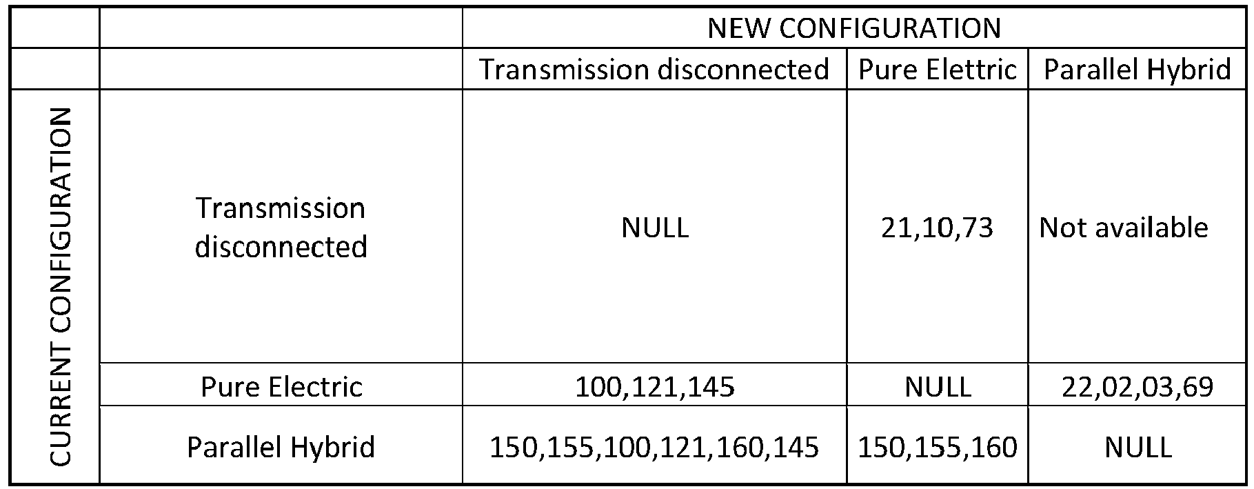
- The first column shows the current configurations:
- Transmission disconnected
- Pure electric
- Parallel hybrid
- The first row shows the "new" configurations:
- Transmission disconnected
- Pure electric
- Parallel hybrid
- It is evident that if the current configuration and the new one coincides, then, there is no change procedure to be performed and therefore the major diagonal is formed by cells set to "NULL".
- The other cells of the table include a sequence of identifiers separated by a separator, for example a comma. Each identifier corresponds to an operation to be performed and the order of the identifiers corresponds to the ordered sequence of operations to be performed.
Table 2 below shows an example of identifier translator: Operation ID Operation to be performed 21 Switching on the propulsion inverter 10 Closing of the clutch of the electric motor 73 Activation of the traction control as a function of the position of the accelerator pedal 22 Turning on the internal combustion engine 2 Synchronization of the revolutions of the internal combustion engine with the rotational speed of the transmission gearbox 3 Closing of the clutch of the internal combustion engine 69 Distributing the torque between the electric motor and the internal combustion engine 100 Cancelling the torque delivered by the electric motor 121 Opening the electric motor clutch 145 Turning off the propulsion inverter 150 Putting the internal combustion engine to idle 155 Opening the internal combustion engine clutch 160 Turning off the internal combustion engine - It is evident that the identifiers can vary according to the hardware configuration of the transmission and the multiple configuration possibilities.
- In a cell of table 1 it is indicated: "not feasible".
- This indication means that there are no identifiers, as the transition from the current configuration to the new configuration is not possible or is not available.
- For example, if the engagement of the internal combustion engine does not involve slip, then it is not possible to pass from the NULL configuration or from a low speed condition to the condition of connecting the internal combustion engine to the transmission, as this would lead to turn off the heat engine.
- The present invention can advantageously be implemented through a computer program comprising coding means for carrying out one or more steps of the method, when this program is executed on a computer. Therefore it is understood that the scope of protection extends to said computer program and also to computer-readable means comprising a recorded message, said computer-readable means comprising program coding means for carrying out one or more steps of the method, when said program is run on a computer.
- Variants of the non-limiting example described are possible, without however departing from the scope of protection of the present invention, including all equivalent embodiments for a person skilled in the art, to the contents of the claims.
- From the description given above, the person skilled in the art is capable of realizing the object of the invention without introducing further constructive details.
Claims (11)
- A method for configuring a control processing unit of a hybrid transmission of a vehicle comprising an internal combustion engine, at least one electric propulsion motor and means for managing the selective connection of the internal combustion engine and/or the electric motor to the hybrid transmission, wherein the processing unit is configured to simulate a microprocessor (CPU) comprising a static Lookup Table Memory wherein a table (Tab 1) of the transitions is stored, wherein a sequence of identifiers is indicated in each cell relating to a transition between two operating modes of the hybrid transmission, wherein each identifier indicates an operation (Task) to be performed.
- Method according to claim 1, wherein said microprocessor is configured so as to comprise a first software module (SCAN LOGIC) configured, for each task (Task) of the sequence, for- Commanding the start of the task,- awaiting for the execution of the task and after verifying the correct execution of the task,- Indicating the task as executed,and wherein said first software module is configured to return the complete execution of each sequence.
- Method according to claim 1 or 2, wherein said microprocessor is configured so as to comprise a third software module (REGISTER LOGIC) configured to receive as input a request for a new transmission operating mode and to provide the memory with the current operating mode of the transmission.
- Method according to any one of claims 1 - 3, wherein said microprocessor is configured so as to comprise a fourth software module (Interrupt handler) arranged to monitor the execution of each operation (Task) of the sequence and to override the commands for changing the transmission operating mode, when a condition of shutdown that prevents execution or completion of execution of a transition between two different operating modes.
- Computer program comprising program coding means configured for carrying out a simulation of a microprocessor according to any one of claims 1 to 4, when said program is run on a control processing unit of a vehicular transmission.
- Computer readable means comprising a recorded program, said computer readable means comprising program coding means configured to simulate a microprocessor according to any one of claims 1 to 4, when said program is run on a unit control processing of a vehicular transmission.
- Hybrid transmission of a vehicle comprising an internal combustion engine, at least one electric propulsion motor and means for managing the selective connection of the internal combustion engine and/or the electric motor to the transmission, at least one electric motor and means for managing the selective connection of the internal combustion engine and/or electric motor to the hybrid transmission, wherein the hybrid transmission further comprises a processing unit to manage transitions between operating modes of the hybrid transmission, wherein the processing unit is configured to simulate a microprocessor (CPU) comprising a memory (Lookup Table Memory) where a table (Tab 1) of the transitions between said operating modes is stored, wherein each cell indicates a sequence of identifiers relating to a transition between two operating modes, each identifier indicating an operation (Task) to be performed.
- Transmission according to claim 7, wherein said microprocessor is configured so as to comprise a first software module (SCAN LOGIC) configured, for each task (Task) of the sequence, to- Command the start of the execution of the task,- wait for the execution of the task and after verifying the correct execution of the task,- Indicate the task as executed,and wherein said first software module is configured to return the complete execution of each sequence.
- Transmission according to claim 7 or 8, wherein said microprocessor is configured so as to comprise a third software module (REGISTER LOGIC) configured to receive as input a request for a new transmission configuration and to provide the memory with the current configuration of the transmission.
- Method according to any one of claims 7 - 9, wherein said microprocessor is configured so as to comprise a fourth software module (Interrupt handler) arranged to monitor the execution of each operation (Task) of the sequence and to overcome the transmission configuration variation, when a stop condition occurs that prevents execution or completion of execution of a transition between two operating conditions.
- A vehicle comprising a hybrid transmission according to any one of claims 7 to 10.
Applications Claiming Priority (1)
| Application Number | Priority Date | Filing Date | Title |
|---|---|---|---|
| IT202200005537 | 2022-03-21 |
Publications (1)
| Publication Number | Publication Date |
|---|---|
| EP4249302A1 true EP4249302A1 (en) | 2023-09-27 |
Family
ID=81928002
Family Applications (1)
| Application Number | Title | Priority Date | Filing Date |
|---|---|---|---|
| EP23161313.4A Pending EP4249302A1 (en) | 2022-03-21 | 2023-03-10 | System and method of configuration of a control processing unit of a hybrid transmission |
Country Status (1)
| Country | Link |
|---|---|
| EP (1) | EP4249302A1 (en) |
Citations (4)
| Publication number | Priority date | Publication date | Assignee | Title |
|---|---|---|---|---|
| US20060112257A1 (en) * | 2004-11-12 | 2006-05-25 | Undy Stephen R | Microprocessor architected state signature analysis |
| US20120277946A1 (en) * | 2010-06-25 | 2012-11-01 | Toyota Jidosha Kabushiki Kaisha | Hybrid vehicle and control method therefor |
| US20150307080A1 (en) * | 2014-04-23 | 2015-10-29 | Toyota Jidosha Kabushiki Kaisha | Control system of hybrid vehicle |
| EP3034370A1 (en) * | 2014-12-19 | 2016-06-22 | Toyota Jidosha Kabushiki Kaisha | Hybrid vehicle |
-
2023
- 2023-03-10 EP EP23161313.4A patent/EP4249302A1/en active Pending
Patent Citations (4)
| Publication number | Priority date | Publication date | Assignee | Title |
|---|---|---|---|---|
| US20060112257A1 (en) * | 2004-11-12 | 2006-05-25 | Undy Stephen R | Microprocessor architected state signature analysis |
| US20120277946A1 (en) * | 2010-06-25 | 2012-11-01 | Toyota Jidosha Kabushiki Kaisha | Hybrid vehicle and control method therefor |
| US20150307080A1 (en) * | 2014-04-23 | 2015-10-29 | Toyota Jidosha Kabushiki Kaisha | Control system of hybrid vehicle |
| EP3034370A1 (en) * | 2014-12-19 | 2016-06-22 | Toyota Jidosha Kabushiki Kaisha | Hybrid vehicle |
Similar Documents
| Publication | Publication Date | Title |
|---|---|---|
| US6735502B2 (en) | Control system and method for a parallel hybrid electric vehicle | |
| CN103625461B (en) | Diagnostic system and method for the lambda sensor of hybrid electric vehicle | |
| US9669822B2 (en) | Method and apparatus for controlling operation of an internal combustion engine for a multi-mode powertrain system | |
| US8989930B2 (en) | Method and apparatus for controlling an engine disconnect clutch in a powertrain system | |
| CN103133157A (en) | System and method for determining when engine has abnormally stopped in a hybrid electric vehicle | |
| CN103010206A (en) | Control apparatus of hybrid vehicle | |
| US20180066622A1 (en) | Method for guaranteeing driving performance of engine and hybrid electric vehicle thereof | |
| KR101490922B1 (en) | Method and system for changing drive mode when battery power of hybrid vehicle is limited | |
| Zhu et al. | NCSU year three final technical report | |
| US9002533B2 (en) | Message transmission control systems and methods | |
| US9122662B2 (en) | Processor safety test control systems and methods | |
| US20210179070A1 (en) | Powertrain controls for an electric motor and an automated manual transmission | |
| CN110341683B (en) | Mode switching torque coordination control method and system for hybrid vehicle | |
| EP4249302A1 (en) | System and method of configuration of a control processing unit of a hybrid transmission | |
| CN109849889A (en) | Power dividing type hybrid vehicle hybrid power drive mode method for handover control | |
| CN112160857B (en) | Dual-motor vehicle engine control method and device, vehicle and storage medium | |
| CN112026748B (en) | Motor failure control method and device, electronic equipment and storage medium | |
| US20160208718A1 (en) | Method and apparatus to stabilize engine state selection using an energy based stabilization strategy for hybrid powertrain systems | |
| US7197382B2 (en) | Method and system for determining engine state of a hybrid electric vehicle | |
| JP2017007642A (en) | Control system | |
| CN115571111A (en) | Mode switching control method for ISG hybrid vehicle power system, vehicle and storage medium | |
| CN113561958B (en) | Dynamic response diagnosis method and system for rear oxygen sensor of hybrid electric vehicle | |
| US20130296135A1 (en) | Method and apparatus for executing a shift path to a target powerstrain state | |
| CN114919565A (en) | Vehicle and torque control method and system thereof | |
| CN111379852B (en) | Gear determining method and system and vehicle |
Legal Events
| Date | Code | Title | Description |
|---|---|---|---|
| PUAI | Public reference made under article 153(3) epc to a published international application that has entered the european phase |
Free format text: ORIGINAL CODE: 0009012 |
|
| STAA | Information on the status of an ep patent application or granted ep patent |
Free format text: STATUS: THE APPLICATION HAS BEEN PUBLISHED |
|
| AK | Designated contracting states |
Kind code of ref document: A1 Designated state(s): AL AT BE BG CH CY CZ DE DK EE ES FI FR GB GR HR HU IE IS IT LI LT LU LV MC ME MK MT NL NO PL PT RO RS SE SI SK SM TR |
|
| STAA | Information on the status of an ep patent application or granted ep patent |
Free format text: STATUS: REQUEST FOR EXAMINATION WAS MADE |