US10831038B2 - Stereo viewer and/or stereo view finder - Google Patents
Stereo viewer and/or stereo view finder Download PDFInfo
- Publication number
- US10831038B2 US10831038B2 US15/554,836 US201515554836A US10831038B2 US 10831038 B2 US10831038 B2 US 10831038B2 US 201515554836 A US201515554836 A US 201515554836A US 10831038 B2 US10831038 B2 US 10831038B2
- Authority
- US
- United States
- Prior art keywords
- stereo
- light shielding
- shielding hood
- view finder
- lens
- Prior art date
- Legal status (The legal status is an assumption and is not a legal conclusion. Google has not performed a legal analysis and makes no representation as to the accuracy of the status listed.)
- Active
Links
Images


Classifications
-
- G—PHYSICS
- G02—OPTICS
- G02B—OPTICAL ELEMENTS, SYSTEMS OR APPARATUS
- G02B30/00—Optical systems or apparatus for producing three-dimensional [3D] effects, e.g. stereoscopic images
-
- G—PHYSICS
- G02—OPTICS
- G02B—OPTICAL ELEMENTS, SYSTEMS OR APPARATUS
- G02B30/00—Optical systems or apparatus for producing three-dimensional [3D] effects, e.g. stereoscopic images
- G02B30/20—Optical systems or apparatus for producing three-dimensional [3D] effects, e.g. stereoscopic images by providing first and second parallax images to an observer's left and right eyes
- G02B30/34—Stereoscopes providing a stereoscopic pair of separated images corresponding to parallactically displaced views of the same object, e.g. 3D slide viewers
- G02B30/37—Collapsible stereoscopes
-
- G—PHYSICS
- G03—PHOTOGRAPHY; CINEMATOGRAPHY; ANALOGOUS TECHNIQUES USING WAVES OTHER THAN OPTICAL WAVES; ELECTROGRAPHY; HOLOGRAPHY
- G03B—APPARATUS OR ARRANGEMENTS FOR TAKING PHOTOGRAPHS OR FOR PROJECTING OR VIEWING THEM; APPARATUS OR ARRANGEMENTS EMPLOYING ANALOGOUS TECHNIQUES USING WAVES OTHER THAN OPTICAL WAVES; ACCESSORIES THEREFOR
- G03B17/00—Details of cameras or camera bodies; Accessories therefor
- G03B17/02—Bodies
-
- G—PHYSICS
- G03—PHOTOGRAPHY; CINEMATOGRAPHY; ANALOGOUS TECHNIQUES USING WAVES OTHER THAN OPTICAL WAVES; ELECTROGRAPHY; HOLOGRAPHY
- G03B—APPARATUS OR ARRANGEMENTS FOR TAKING PHOTOGRAPHS OR FOR PROJECTING OR VIEWING THEM; APPARATUS OR ARRANGEMENTS EMPLOYING ANALOGOUS TECHNIQUES USING WAVES OTHER THAN OPTICAL WAVES; ACCESSORIES THEREFOR
- G03B17/00—Details of cameras or camera bodies; Accessories therefor
- G03B17/56—Accessories
- G03B17/561—Support related camera accessories
-
- G—PHYSICS
- G03—PHOTOGRAPHY; CINEMATOGRAPHY; ANALOGOUS TECHNIQUES USING WAVES OTHER THAN OPTICAL WAVES; ELECTROGRAPHY; HOLOGRAPHY
- G03B—APPARATUS OR ARRANGEMENTS FOR TAKING PHOTOGRAPHS OR FOR PROJECTING OR VIEWING THEM; APPARATUS OR ARRANGEMENTS EMPLOYING ANALOGOUS TECHNIQUES USING WAVES OTHER THAN OPTICAL WAVES; ACCESSORIES THEREFOR
- G03B19/00—Cameras
- G03B19/02—Still-picture cameras
- G03B19/16—Pin-hole cameras
-
- G—PHYSICS
- G03—PHOTOGRAPHY; CINEMATOGRAPHY; ANALOGOUS TECHNIQUES USING WAVES OTHER THAN OPTICAL WAVES; ELECTROGRAPHY; HOLOGRAPHY
- G03B—APPARATUS OR ARRANGEMENTS FOR TAKING PHOTOGRAPHS OR FOR PROJECTING OR VIEWING THEM; APPARATUS OR ARRANGEMENTS EMPLOYING ANALOGOUS TECHNIQUES USING WAVES OTHER THAN OPTICAL WAVES; ACCESSORIES THEREFOR
- G03B35/00—Stereoscopic photography
- G03B35/18—Stereoscopic photography by simultaneous viewing
-
- G—PHYSICS
- G02—OPTICS
- G02B—OPTICAL ELEMENTS, SYSTEMS OR APPARATUS
- G02B27/00—Optical systems or apparatus not provided for by any of the groups G02B1/00 - G02B26/00, G02B30/00
- G02B27/01—Head-up displays
- G02B27/0101—Head-up displays characterised by optical features
- G02B2027/0132—Head-up displays characterised by optical features comprising binocular systems
- G02B2027/0136—Head-up displays characterised by optical features comprising binocular systems with a single image source for both eyes
-
- G—PHYSICS
- G02—OPTICS
- G02B—OPTICAL ELEMENTS, SYSTEMS OR APPARATUS
- G02B7/00—Mountings, adjusting means, or light-tight connections, for optical elements
- G02B7/02—Mountings, adjusting means, or light-tight connections, for optical elements for lenses
- G02B7/04—Mountings, adjusting means, or light-tight connections, for optical elements for lenses with mechanism for focusing or varying magnification
- G02B7/06—Focusing binocular pairs
-
- G—PHYSICS
- G02—OPTICS
- G02B—OPTICAL ELEMENTS, SYSTEMS OR APPARATUS
- G02B7/00—Mountings, adjusting means, or light-tight connections, for optical elements
- G02B7/02—Mountings, adjusting means, or light-tight connections, for optical elements for lenses
- G02B7/12—Adjusting pupillary distance of binocular pairs
-
- G—PHYSICS
- G03—PHOTOGRAPHY; CINEMATOGRAPHY; ANALOGOUS TECHNIQUES USING WAVES OTHER THAN OPTICAL WAVES; ELECTROGRAPHY; HOLOGRAPHY
- G03B—APPARATUS OR ARRANGEMENTS FOR TAKING PHOTOGRAPHS OR FOR PROJECTING OR VIEWING THEM; APPARATUS OR ARRANGEMENTS EMPLOYING ANALOGOUS TECHNIQUES USING WAVES OTHER THAN OPTICAL WAVES; ACCESSORIES THEREFOR
- G03B17/00—Details of cameras or camera bodies; Accessories therefor
- G03B17/56—Accessories
- G03B17/566—Accessory clips, holders, shoes to attach accessories to camera
Definitions
- the present invention relates to stereo viewers and/or stereo view finders, and in particular to a stereo viewer used when viewing a stereo image and/or a stereo view finder used when photographing a stereo image.
- a stereo viewer that stereoscopically views a pair of stereo images of different viewpoints photographed at two points spaced apart from each other through a lens with both eyes of an observer, and a stereo view finder used when photographing the stereo images are conventionally known.
- a stereo viewer in which two screens and an optical viewer including a pair of lenses and being provided in a freely pivoting manner on a lower shell body by way of a crease hinge are arranged in a plastic case configured by coupling an upper shell body and the lower shell body by way of the crease hinge is known (see e.g., patent document 1).
- stereo view finder for example, a stereo view finder attached to a lower side of an imaging unit serving as an electronic device such as a digital stereo camera, and the like to separately observe a pair of left and right TFT color liquid crystal displays arranged in a body with a pair of left and right eye lenses is known (see e.g., patent document 2).
- the optical lens becomes large, and when viewing an electronic display such as the digital stereo camera and the like, a focal length of the optical lens becomes long and hence the lens needs to be spaced apart from the electronic display, which enlarges an outer shape. Furthermore, when viewing the stereo image outside, a luminance of the electronic display relatively lowers due to the influence of outside light and the stereo image becomes difficult to visualize.
- the body tends to become large, and hence the portability of when photographing the stereo image outside is poor.
- the present invention is proposed to achieve the object described above, where the invention described in an embodiment provides a stereo viewer and/or a stereo view finder used in an electronic device equipped with an electronic display for displaying a pair of stereo images, the stereo viewer and/or the stereo view finder including a foldable light shielding hood attached on the electronic display; and a magnifying lens including a pair of lenses for viewing the stereo image, the magnifying lens being attached to an inner wall surface of the light shielding hood by way of a hinge and being developable to be parallel to the electronic display.
- the light shielding hood prevents the outside light from entering the electronic display, and thus the stereo image displayed on the electronic display can be easily visualized, and furthermore, since the light shielding hood can be compactly folded and stored, it can be easily and conveniently carried outside.
- the invention described in another embodiment provides, in addition to the configuration of the shared structure of the stereo viewer and/or the stereo view finder according to a first embodiment, the stereo viewer and/or the stereo view finder that further includes a magnifying lens raising/lowering mechanism capable of raising/lowering the magnifying lens in a perpendicular direction perpendicular to the electronic display.
- the magnifying lens can be moved farther away from or closer to the electronic display, the diopter of the magnifying lens can be adjusted according to the visibility degree of the observer.
- the invention described in another embodiment provides, in addition to the configuration of the shared structure of the stereo viewer and/or the stereo view finder according to a prior embodiment, the stereo viewer and/or the stereo view finder in which the magnifying lens raising/lowering mechanism can raise/lower the magnifying lens to an upper side in the perpendicular direction than the light shielding hood.
- the distance between the magnifying lens and the electronic display is ensured to be longer than the height of the light shielding hood, and hence the diopter of the magnifying lens can be adjusted according to the visibility degree of the observer regardless of the height of the light shielding hood.
- the invention described in another embodiment provides, in addition to the configuration of the shared structure of the stereo viewer and/or the stereo view finder according to prior embodiments, the stereo viewer and/or the stereo view finder in which the magnifying lens raising/lowering mechanism includes a column coupled to the magnifying lens by way of a hinge, and attached to the inner wall surface of the light shielding hood so as to be raised/lowered in the perpendicular direction; a worm screw attached to a side of the column, the worm screw being turnable about a rotation axis extending in the perpendicular direction; and an input gear arranged to gear with the worm screw, the input gear turning the worm screw to raise/lower the column.
- the magnifying lens raising/lowering mechanism includes a column coupled to the magnifying lens by way of a hinge, and attached to the inner wall surface of the light shielding hood so as to be raised/lowered in the perpendicular direction; a worm screw attached to a side of the column, the worm screw being turnable about a rotation axis
- the column is raised/lowered in the perpendicular direction through the worm screw, and the magnifying lens is moved farther away from or closer to the electronic display by simply turning the input gear, and hence the diopter can be easily adjusted according to the visibility degree of the photographer.
- the invention described in anther embodiment provides, in addition to the configuration of the shared structure of the stereo viewer and/or the stereo view finder according to a prior embodiment, the stereo viewer and/or the stereo view finder in which a raising/lowering stopper that inhibits the gearing of the worm screw and the input gear is arranged in a tooth groove of the input gear.
- the stopper is interposed between the worm screw and the input gear, the turning of the worm screw is restrained, and the column and the magnifying lens are positioned, and hence the diopter can be adjusted according to the visibility degree of the observer and the position of the magnifying lens with respect to the electronic display can be fixed.
- the invention described in another embodiment provides, in addition to the configuration of the shared structure of the stereo viewer and/or the stereo view finder according to a prior embodiment, the stereo viewer and/or the stereo view finder that further includes a partition plate bridged between the inner wall surface of the light shielding hood and an opposing wall surface opposing the inner wall surface, the partition plate partitioning a view field of the pair of lenses.
- the angular view field of the pair of lenses is partitioned by the partition plate, and thus the observer can easily stereoscopically view the pair of stereo images.
- the invention described in an embodiment provides, in addition to the configuration of the shared structure of the stereo viewer and/or the stereo view finder according to a prior embodiment, the stereo viewer and/or the stereo view finder in which the partition plate has one end attached to a back inner wall surface of the light shielding hood by way of a hinge to turn about a rotation axis perpendicular to the electronic display.
- the partition plate can be opened/closed according to the development and the storage of the light shielding hood.
- the invention described in another embodiment provides, in addition to the configuration of the shared structure of the stereo viewer and/or the stereo view finder according to a prior embodiment, the stereo viewer and/or the stereo view finder that further includes a turning stopper that integrally fixes the partition plate to the light shielding hood and regulates the turning of the partition plate when the light shielding hood is folded, and that separates the partition plate and the light shielding hood when the light shielding hood is developed.
- the partition plate can be suppressed from accidentally developing when storing the light shielding hood, and the partition plate can be easily developed when developing the light shielding hood.
- the invention described in another embodiment provides, in addition to the configuration of the shared structure of the stereo viewer and/or the stereo view finder according to a prior embodiment, the stereo viewer and/or the stereo view finder in which the turning stopper includes a hook portion, arranged to be slidable in an insertion hole formed in the opposing wall surface of the light shielding hood, to hook the other end of the partition plate.
- the partition plate can be separated from the opposing wall surface by simply sliding the stopper.
- the invention described in another embodiment provides, in addition to the configuration of the shared structure of the stereo viewer and/or the stereo view finder according to a prior embodiment, the stereo viewer and/or the stereo view finder that further includes an inter-lens distance adjustment mechanism that adjusts an inter-lens distance between the pair of lenses.
- the inter-lens distance between the pair of lenses can be adjusted according to the eye interval of the observer.
- the invention described in another embodiment provides, in addition to the configuration of the shared structure of the stereo viewer and/or the stereo view finder according to a prior embodiment, the stereo viewer and/or the stereo view finder in which the inter-lens distance adjustment mechanism includes a pair of lens holders that turnably accommodate the lenses, respectively, about the rotation axis perpendicular to the electronic display.
- the inter-lens distance between the pair of lenses can be adjusted according to the eye width of the observer by turning the lens holder about the rotation axis.
- the invention described in another embodiment provides, in addition to the configuration of the shared structure of the stereo viewer and/or the stereo view finder according to a prior embodiment, the stereo viewer and/or the stereo view finder in which the inter-lens distance adjustment mechanism includes a segment gear formed on respective opposing surfaces of the pair of lens holders to gear with each other.
- the invention described in another embodiment provides, in addition to the configuration of the shared structure of the stereo viewer and/or the stereo view finder according to a prior embodiment, the stereo viewer and/or the stereo view finder in which the inter-lens distance adjustment mechanism includes an excessive turning stopper that regulates an excessive turning of the lens holder.
- the stopper suppresses the excessive rotation of the lens holder interval, whereby the lens interval can be adjusted to within a desired range.
- the invention described in another embodiment provides, in addition to the configuration of the shared structure of the stereo viewer and/or the stereo view finder according to a prior embodiment, the stereo viewer and/or the stereo view finder in which the inter-lens distance adjustment mechanism includes a base plate with holes, each being larger than the left and right lenses, the pair of left and right lens holders are installed on the base plate, and the base holder and the pair of lens holders are turnably coupled with a pin at a respective lower end as a center.
- a hole for arranging a camshaft in a rotatably standing manner is formed at a center of the base plate, the cam shaft having two left and right cams fixed is arranged in a standing manner in the hole, and a side end of each of the left and right lens holders is brought into contact with the left and right cams by a spring.
- a mechanism for adjusting an interval of the lens holders to a suitable state of an observer by the left and right cams by turning the upper end of the camshaft with a finger is provided.
- the interval of the left and right lenses can be adjusted by simply turning the camshaft, and the entire mechanism can be miniaturized.
- the invention described in another embodiment is a stereo viewer and/or a stereo view finder of an electronic display method that is used in association with a digital stereo camera and that displays a pair of stereo images, the stereo viewer and/or the stereo view finder being a stereo viewer and/or a stereo view finder according to a prior embodiment, where a collimation pattern same on the left and right is displayed on the left and right display screens by software.
- the left and right patterns merge to appear as one stereoscopic model, and a normal stereoscopic vision can be photographed by carrying out the photographing such that the stereoscopic vision to photograph appears on the other side of the stereoscopic model pattern.
- the invention described in another embodiment is a stereo viewer and/or a stereo view finder, the stereo viewer and/or the stereo view finder being a stereo viewer and/or a stereo view finder according to a prior embodiment, where a stereo slide is inserted to a slot provided at an upper part of the electronic display to enable the stereo slide formed on a film to be viewed by white displaying the left and right electronic displays and using the displays as a backlight.
- the electronic display can be used as a backlight, and the film type stereo slide can be viewed even with the electronic display.
- the display, and the like do not drop by its own weight, and when lowering the display to a lower position, an operation of further turning toward a lower side than the lower position due to the effect of deriving the face coupling acts, and furthermore, when raising the display to an upper side, an operation of further turning toward an upper side than the upper position acts, so that the display is not carelessly moved in the normal state by being restrained at the position of 90° in the upper and lower range right before with the stopper.
- the present invention enables the stereo image displayed on the electronic display to be easily visualized, and enables easy and convenient carrying as it can be freely folded even when used as the stereo viewer when photographing the stereo image outside. Furthermore, as the electronic display can also be used as a backlight, it can also be used as a film type stereo viewer.
- FIG. 1 is a perspective view showing a stereo viewer/stereo view finder according to a first example of the present invention
- FIG. 2 is a schematic view showing a display interval of a pair of stereo images
- FIG. 3 is an example of displaying a pattern, same on left and right, on an electronic display with software, and is a schematic view showing the stereo image, where FIG. 3( a ) is a view showing an aspect ratio of 3:4, FIG. 3( b ) is a view showing an aspect ratio of 1:1.41, FIG. 3( c ) is a view showing an aspect ratio of 1:1.5, and FIG. 3( d ) is a view showing an aspect ratio of 9:16;
- FIG. 4 is a schematic view showing a state in which photographing information is displayed on the electronic display
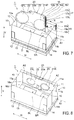
- FIG. 5 is a perspective view showing a state in which a light shielding hood is being folded
- FIG. 6 is a perspective view showing a state in which the light shielding hood is folded
- FIG. 7 is a partially cutout perspective view showing a stereo viewer/stereo view finder according to a second example of the present invention.
- FIG. 8 is a perspective view showing a first variant of the stereo viewer/stereo view finder shown in FIG. 7 ;
- FIG. 9 is a perspective view showing a second variant of the stereo viewer/stereo view finder shown in FIG. 7 ;
- FIG. 10 is a perspective view showing a stereo viewer/stereo view finder according to a third example of the present invention.
- FIG. 11 is an enlarged cross-sectional view of a main part of a partition plate and a stopper shown in FIG. 10 ;
- FIG. 12 is a perspective view showing a stereo viewer/stereo view finder according to a fourth example of the present invention.
- FIG. 13 is a plan view showing a magnifying lens and a lens interval distance adjustment mechanism shown in FIG. 12 ;
- FIG. 14 a is an explanatory view showing another embodiment of the stereo viewer/stereo view finder
- FIG. 14 b is an explanatory view showing another embodiment of the stereo viewer/stereo view finder
- FIG. 14 c is an explanatory view showing another embodiment of the stereo viewer/stereo view finder
- FIG. 15 is a perspective view of a light shielding hood of another mode
- FIG. 16 is a perspective view showing a state in which the stereo view finder is attached to the stereo camera
- FIG. 17 a is a perspective view showing a state in which the stereo view finder is attached to the stereo camera.
- FIG. 17 b is a cross-sectional view showing the state in which the stereo view finder is attached to the stereo camera.
- the present invention provides a stereo viewer and/or a stereo view finder used in an electronic device equipped with an electronic display for displaying a pair of stereo images, the stereo viewer and/or the stereo view finder including a foldable light shielding hood attached on the electronic display; and a magnifying lens including a pair of lenses for viewing the stereo image, the magnifying lens being attached to an inner wall portion of the light shielding hood by way of a hinge and being developable to be parallel to the electronic display.
- a stereo viewer/stereo view finder according to a first example of the present invention will be described below based on FIGS. 1 to 6 .
- a stereo viewer/stereo view finder 1 is applied to a digital stereo camera (not illustrated) including a liquid crystal display D serving as an electronic display, and used as a viewer and a view finder.
- the liquid crystal display D may be an organic EL.
- the digital stereo camera may include two of each of a lens and an imaging element, or may include three of each of a lens and an imaging element so that an inter-optical axis distance of the photographing lenses can be changed according to a distance with a subject.
- a pair of stereo images SR, SL are displayed so as to be projected onto a reference dimension display screen S.
- the “reference dimension display screen S” is a position where visual fields of an observer viewing the stereo images SR, SL coincide.
- the pair of stereo images SL, SR are to be displayed on the liquid crystal display D while being spaced apart by the display interval W 1 from each other, where a pair of display windows WR, WL spaced apart by the display interval W 1 from each other may be provided on the liquid crystal display D, and the stereo images SR, SL may be displayed on the display windows WR, WL, respectively, as shown in FIG. 3 .
- the distance L 0 from the eye to the reference dimension display screen S is 2500 mm
- the reference dimension display screen width W 0 is 1800 mm
- the width W 2 of the display windows WR, WL is 55 mm
- a focal length of the lens (pair of left and right magnifying lenses) 20 of the viewer to be described later is theoretically 76.39 mm, but a focal length of 70 mm to 80 mm may be used without arising any problem. This is because the visibility degree of the user is adjusted, and further correction is sometimes required depending on the visibility degree of the user (it may be preferable for a person whose visibility degree is extremely deviated from a standard value to further use a magnifying lens of a focal length outside the above range).
- a collimation pattern P may be arbitrarily displayed in a manner superimposed on the stereo images SR, SL in the display windows WR, WL.
- a composition of a subject thus can be easily checked during photographing and after photographing.
- a distance at which a stereoscopic model of the collimation pattern P can be viewed is the position where the left and right visual fields coincide, and hence the stereoview can be seen at the distance of 2500 mm.
- 2500 mm is a set value, and this is not the only case.
- the photographing should be carried out such that the stereoscopic model of the subject can be seen on the other side of the collimation pattern. If the stereoscopic model of the subject is seen on the near side than the stereoscopic model of the collimation pattern, the collimation pattern may be seen in a doubly shifted manner. Even if the stereoscopic model of the subject is seen on the near side than the collimation pattern, photographing can be carried out if the collimation pattern appearing at the back does not appear shifted.
- an aspect ratio of the display windows WR, WL may be arbitrarily changed.
- the display interval W 1 between the pair of stereo images SR, SL can be maintained constant before and after the change of the aspect ratio by changing a height H while maintaining the width W 2 of the display windows SR, SL constant.
- a data display window WD for displaying photograph data such as a resolution and edit data of the stereo images SR, SL displayed during photographing and after photographing is preferably displayed in a region excluding the display windows WR, WL in the liquid crystal display DS.
- the photograph data or the edit data is thus avoided from being displayed in a manner superimposed on the stereo images SR, SL, and the stereo images SR, SL can be more easily viewed.
- the collimation pattern displayed on the left and right screens is necessary by any means, but as this may feel bothersome (depends on preference of photographer), it may be displayed only when attached to the camera and photographed as the stereo view finder, may be ON/OFF switch displayed with a push button, and the like, or may be displayed with a timer for a few seconds only when the shutter button is half pushed. Furthermore, the collimation pattern may be displayed for examination when used as the stereo viewer. Generally, however, it is preferred that the collimation pattern is displayed at the time of photographing, and not displayed when being used as the stereo viewer.
- the stereo viewer/stereo view finder 1 includes a light shielding hood 10 attached on the liquid crystal display D, and a pair of magnifying lenses 20 that can be developed to be parallel to the liquid crystal display D.
- the light shielding hood 10 is configured by a front wall portion 11 , a back wall portion 12 , a left wall portion 13 , and a right wall portion 14 , each arranged to stand along a peripheral edge of the rectangular liquid crystal display D, and the light shielding hood 10 is foldable, as will be described later.
- a lower part of the front wall portion 11 is fixed to be turnable about a rotation axis A 1 with respect to a hood frame 15 .
- the left wall portion 13 is configured to be bendable toward an inner side at a central hinge 13 a .
- the right wall portion 14 is configured to be bendable toward an inner side at a central hinge 14 a.
- the light shielding hood 10 may be freely detachable/attachable with respect to the liquid crystal display D, or may be integrally attached to the liquid crystal display D.
- the magnifying lens 20 includes a pair of lenses 21 R, 21 L, and a lens holder 22 for accommodating the pair of lenses 21 R, 21 L, respectively.
- the pair of lenses 21 R, 21 L are arranged in the lens holder 22 such that an inter-optical axis distance of the lenses 21 R, 21 L becomes equal to the eye interval B (e.g., 65 mm) of a general observer.
- the lens holder 22 is attached to a front inner wall surface 11 a of the light shielding hood 10 by way of a hinge 23 , and is able to turn 90° about a rotation axis A 2 of the hinge 23 .
- the magnifying lens 20 can be developed to be substantially parallel to the liquid crystal display D by lifting up the lens holder 22 approximately 90° from the front inner wall surface 11 a .
- a reference symbol 23 a in FIG. 1 indicates a grip for turning the lens holder 22 .
- FIGS. 5 and 6 a procedure for folding the light shielding hood 10 will be described based on FIGS. 5 and 6 .
- the magnifying lens 20 is omitted.
- the light shielding hood 10 can be compactly folded by folding the left wall portion 13 and the right wall portion 14 in substantially half, respectively, and folding the front wall portion 11 toward the inner side while sliding the back wall portion 12 toward the front wall portion 11 on the hood frame 15 .
- the left wall portion 13 and the right wall portion 14 can be opened by a biasing force of a torsion coil spring (not illustrated) installed at the central hinges 14 a , 15 a by simply lifting up the front wall portion 11 , so that the light shielding hood 10 can be easily and conveniently developed.
- a torsion coil spring not illustrated
- the light shielding hood 10 prevents the outside light from entering the liquid crystal display D when photographing or viewing the stereo image outside, so that the stereo images SR, SL displayed on the liquid crystal display D can be easily visualized. Furthermore, when the hood is stored, the light shielding hood 10 is compactly small, and can be easily and conveniently carried around.
- FIG. 7 A redundant description on a configuration common between the stereo viewer/stereo view finder according to the present example and the stereo viewer/stereo view finder according to the first example described above will be omitted.
- the stereo viewer/stereo view finder 1 includes a magnifying lens raising/lowering mechanism X that can raise/lower the magnifying lens 20 in a perpendicular direction V perpendicular with respect to the liquid crystal display D.
- the magnifying lens raising/lowering mechanism X includes a column 16 fitted into a slit 11 b having a horseshoe shaped cross-section formed along the perpendicular direction V at the center of the front inner wall surface 11 a , a worm screw 17 extended along the perpendicular direction V at a side end 16 a of the column 16 , and an input gear 18 that gears with the worm screw 17 .
- the column 16 is connected to the magnifying lens 20 by way of the hinge 23 .
- an upper end 22 a of the lens holder 22 is coupled to an upper end 16 b of the column 16 by way of the hinge 23 .
- the column 16 is arranged independent from the front wall portion 11 , and can be freely raised/lowered in the perpendicular direction V in the slit 11 b and can be raised to the upper side in the perpendicular direction V than the front wall portion 11 .
- the liquid crystal display D and the magnifying lens 20 can be spaced apart by a length (e.g., 15 mm) of a column 15 projected out to the upper side from the upper end of the front wall portion 11 , in addition to a height (e.g., 50 mm) of the upper end of the front wall portion 11 .
- the magnifying lens 20 thus can be raised at an installation distance (e.g., 65 mm) longer than the height of the light shielding hood 10 .
- a supporting arm 16 c is arranged to project out toward a horizontal direction H perpendicular to the perpendicular direction V from the upper part and the lower part of the side end 16 a of the column 16 .
- the worm screw 17 includes a worm shaft 17 a turnably supported by the supporting arm 16 c , and a worm 17 b formed on a peripheral surface of the worm shaft 17 a .
- the worm screw 17 is turned about the worm shaft 17 a in cooperation with the turning of the input gear 18 . It is raised/lowered in cooperation with the turning of the worm screw 17 .
- a fine adjustment knob 17 c integrally attached with the worm shaft 17 a , and provided to cause the worm screw 17 to turn about the worm shaft 17 a is arranged at an upper end of the worm shaft 17 a.
- the input gear 18 is axially supported by a rotation shaft 18 a arranged in a projecting manner on the front inner wall 11 a .
- a worm wheel, a helical gear, and the like, for example, may be used for the input gear 18 .
- the input gear 18 includes a projecting portion 18 b that projects out outward from the front wall portion 11 .
- the observer can turn the input gear 18 about the rotation shaft 18 by way of the projecting portion 18 b.
- a raising/lowering stopper (not illustrated) that inhibits the gearing of the worm 17 b and the input gear 18 is arranged in a tooth groove of the input gear 18 .
- a reference symbol 18 c refers to a marker indicating a position where the raising/lowering stopper is arranged, that is, a rotation limit position of the input gear 18 .
- the raising/lowering stopper merely needs to inhibit the gearing of the worm 17 b and the input gear 18 , and for example, may be formed by attaching a metal piece to the tooth groove and filling the tooth groove, may be formed by welding a metal piece in the tooth groove and filling the tooth groove, or may be formed by leaving one tooth groove without performing gear cutting when carrying out the gear cutting.
- the observer When raising the magnifying lens 20 , the observer turns the projecting portion 18 b of the input gear 18 in a clockwise direction about the rotation shaft 18 a . When lowering the magnifying lens 20 , the observer turns the projecting portion 18 b of the input gear 18 in a counterclockwise direction about the rotation shaft 18 a .
- the raising/lowering of the magnifying lens 20 can be switched by changing the turning direction of the input gear 18 described above, and hence a case of raising the magnifying lens 20 will be described below.
- the worm 17 b and the input gear 18 are geared, and the worm screw 17 is raised upward in the perpendicular direction V in cooperation with the turning of the input gear 18 .
- the raising/lowering stopper is interposed between the worm 17 b and the input gear 18 , so that the turning of the worm screw 17 is stopped, and the column 16 and the magnifying lens 20 are positioned
- the raising/lowering stopper can be arranged according to the focal length of the magnifying lens 20 and the visibility degree of the observer, so that the diopter adjustment can be easily carried out and the magnifying lens 20 can be fixed.
- the position of the magnifying lens 20 with respect to the liquid crystal display D can be fine adjusted.
- the stereo viewer/stereo view finder 1 can adjust the diopter of the magnifying lens 20 , in addition to the effect of the stereo viewer/stereo view finder of the first example.
- the magnifying lens raising/lowering mechanism X may be configured with the column 16 , a stopper hole 16 d provided at the lower part of the column 16 , and a stopper pin 16 e inserted into the stopper hole 16 d to position the column 16 at a desired position.
- the column 16 can be positioned by simply inserting the stopper pin 16 e into the stopper hole 16 d after raising the column 16 to the desired position, whereby the magnifying lens raising/lowering mechanism X can be provided at low cost.
- the light shielding hood 10 may have a slide holder 19 arranged on the lower side of the hood frame 15 , where the hood frame 15 and the slide holder 19 may form a slot 19 a for inserting a silver salt stereo slide SS, and the liquid crystal display D may display white as a backlight of the silver salt slide SS.
- the distance between the eye of the observer and the silver salt stereo slide SS is shorter than the distance between the eye of the observer and the liquid crystal display D, and thus the observer can arbitrarily select the silver stereo slide SS and the liquid crystal display D by raising/lowering the magnifying lens 20 in the perpendicular direction V to adjust the diopter.
- the diopter adjustment differs among individual users, and thus needs to be adjustable to different values depending on the individual users, and at the same time, for example, needs to be immediately adjusted to a constant position any time when used by the same user, where the structure shown in FIG. 7 has such elements.
- the focus adjustment needs to be changed for when looking at the liquid crystal display and for when looking at the silver salt stereo picture, but such adjustment can be responded by simply turning the fine adjustment knob 17 c of FIG. 7 .
- adjustment position is adjusted to a constant position at the time of use.
- the adjustment position is always reproduced to the constant position by pressing the stopper against the groove and the like on the outer side of the fine adjustment knob 17 c with a spring, and the like to provide a so-called click stop mechanism, or by applying resistance with respect to rotation so as not to easily rotate.
- a discharge lever 19 b for mounting the silver salt stereo slide SS may be provided.
- the silver salt stereo slide SS can be easily inserted and retracted.
- a black line between the liquid crystal pixels may stand out. If the black line stands out when looking at the silver salt stereo slide, the image quality may significantly lower.
- the diffuser may simply be a white film-like sheet, and two of such sheets may be inserted simultaneously with the stereo slide but should be fixed through some method when viewing the stereo slide (not illustrated).
- the diffuser and the stereo slide are preferably spaced apart as much as possible.
- FIGS. 10 and 11 A redundant description on a configuration common between the stereo viewer/stereo view finder according to the present example and the stereo viewer/stereo view finder according to the first example described above will be omitted.
- the stereo viewer/stereo view finder 1 includes a partition plate 30 that partitions the visual fields of the pair of lenses 21 R, 21 L.
- a supporting side end 30 a of the partition plate 30 is attached to a back inner wall surface 12 a facing the front inner wall surface 11 a by way of a hinge (not illustrated), and the partition plate 30 can be turned about a rotation axis A 3 perpendicular to the liquid crystal display D. Furthermore, a biasing force in a direction of developing the partition plate 30 , that is, in a clockwise direction in the plane of drawing about the rotation axis A 3 in FIG. 10 acts on the partition side end 30 a of the partition plate 30 by a torsion coil spring (not illustrated) of the hinge.
- a turning side end 30 b of the partition plate 30 is hooked to a turning stopper 40 located in a state parallel to the perpendicular direction V and provided to be slidable in the horizontal direction H, and integrally fixed to the back wall portion 12 of the light shielding hood 10 .
- the turning stopper 40 includes an L-shaped hook portion 41 that is inserted into an insertion hole 12 b formed in the back wall portion 12 of the light shielding hood 10 to hook to the turning side end 30 b of the partition plate 30 at the distal end, a U-shaped spring 42 that biases the hook portion 41 from the outer side toward the inner side in the horizontal direction H, and a guide portion 43 formed to a tapered shape from the outer side toward the inner side in the horizontal direction H at the distal end of the hook portion 41 .
- the biasing force of the torsion coil spring causes the partition plate 30 to turn until the rotation side end 30 b of the partition plate 30 makes contact with a stopper pin 11 c provided on the lower side of the magnifying lens 20 , so that the partition plate 30 is bridged between the front inner wall surface 11 a and the back inner wall surface 12 a.
- the partition plate 30 slides the hook portion 41 from the inner side to the outer side in the horizontal direction H against the force of biasing the hook portion 41 from the outer side to the inner side in the horizontal direction H of the U-shaped spring 42 .
- the hook portion 41 is sled from the outer side to the inner side in the horizontal direction H to hook with the turning side end 30 b of the partition plate 30 by the biasing force of the U-shaped spring 42 , and the partition plate 30 is fixed to the back inner wall surface 12 a.
- the stereo viewer/stereo view finder 1 can enable the pair of stereo images SR, SL to be easily stereoscopically viewed by partitioning the visual fields of the pair of stereo images SR, SL with the partition plate 30 , in addition to the effect of the stereo viewer/stereo view finder 1 of the first example. Furthermore, the partition plate 30 can be opened/closed according to the time of development and time of storage of the light shielding hood 10 .
- FIGS. 12 and 13 A redundant description on a configuration common between the stereo viewer/stereo view finder according to the present example and the stereo viewer/stereo view finder according to the first example described above will be omitted.
- the magnifying lens 20 is configured by a pair of lenses 21 R, 21 L, a pair of lens holders 22 R, 22 L for accommodating the lenses 21 R, 21 L, respectively, and a supporting board 24 mounted with the pair of lens holders 22 R, 22 L and coupled to the front wall portion 11 by way of the hinge 23 .
- the pair of lens holders 22 R, 22 L are axially supported by pins 25 R, 25 L, respectively, arranged in a projecting manner on the supporting board 24 .
- a distance between the pins 25 R, 25 L is set to 65 mm, and the inter-optical axis distance (hereinafter referred to as “inter-lens distance) of the pair of lenses 22 R, 22 L is usually set to 65 mm, which is equal to the distance between the pins 25 R, 25 L.
- the pins 25 R, 25 L are respectively arranged on the upper side of the pair of lenses 22 R, 22 L.
- the specific arrangement positions of the pins 25 R, 25 L merely need to be such that the inter-lens distance can be adjusted, and may be any place, except for a line connecting the centers of the pair of lenses 22 R, 22 L, as long as a line connecting the pins 25 R, 25 L is parallel to the line connecting the centers of the lenses 22 R, 22 L.
- An inter-lens distance adjustment mechanism Y that can adjust the inter-lens distance between the pair of lenses 21 R, 21 L includes the pair of lens holders 22 R, 22 L described above, and segment gears 26 R, 26 L formed at an opposing surface 22 b of the pair of lens holders 22 R, 22 L to be able to gear with each other.
- the inter-lens distance becomes narrower when the lens holders 22 R, 22 L are turned to bring the pair of lenses 21 R, 21 L closer to each other, and the inter-lens distance becomes wider when the lens holders 22 R, 22 L are turned to separate the pair of lenses 21 R, 21 L away from each other, and hence the inter-lens distance between the pair of lenses 21 R, 21 L can be adjusted according to an eye width of the observer.
- segment gears 26 R, 26 L gear with each other and hence the lens holders 22 R, 22 L are turned in cooperation when the lens holders 22 R, 22 L are turned, the work load involved in the adjustment of the inter-lens distance can be alleviated.
- the inter-lens distance adjustment mechanism Y includes an excessive turning stopper 27 that regulates the excessive turning of the lens holders 22 R, 22 L.
- the excessive turning stopper 27 includes an excessive approaching stopper 27 a that prevents the pair of lens holders 22 R, 22 L from approaching in excess, and an excessive separating stopper 27 b that prevents the pair of lens holders 22 R, 22 L from separating in excess.
- the excessive approaching stopper 27 a is a projection piece arranged in a projecting manner from the opposing surface 22 b at the back part of the lens holder 22 R, 22 L, and is integrally formed with the lens holder 22 R, 22 L.
- the excessive approaching stopper 27 a is arranged such that the excessive approaching stoppers 27 a make contact with each other when the inter-lens distance reaches a predetermined lower limit value (e.g., 58 mm). Specific arrangement position and length of the excessive approaching stopper 27 a are arbitrarily set according to the lower limit value of the inter-lens distance.
- the excessive separating stopper 27 b is a pin arranged in a cutout portion 22 c , in which one part of the opposing surface 22 b of the lens holder 22 R, 22 L is cut out to a rectangular shape, and arranged in a standing manner on the supporting board.
- the excessive separating stopper 27 b is arranged such that the excessive separating stopper 27 b makes contact with an inner peripheral surface 22 d of the cutout portion 22 c when a lens interval reaches a predetermined upper limit value (e.g., 72 mm).
- the arrangement position and the size of the excessive separating stopper 27 b are arbitrarily set according to the upper limit value of the inter-lens distance.
- the excessive rotation stopper 27 suppresses the excessive turning of the lens holders 22 R, 22 L, whereby the inter-lens distance between the pair of lenses 21 R, 21 L can be smoothly adjusted within a desired range.
- the stereo viewer/stereo view finder 1 according to the present example can adjust the inter-lens distance according to the eye interval of the observer, in addition to the effect of the stereo viewer/stereo view finder of the first example.
- a pair of left and right lens units 50 shown in FIGS. 14 a , 14 b , and 14 c is a different embodiment from that of the stereo viewer/stereo view finder 1 shown in FIG. 12 , where the display D, the light shielding hood 10 , the column 16 , and the like other than the lens unit are portions common with FIG. 12 .
- the lens unit 50 shown in FIG. 14 a has a base plate 240 attached in a state turnable by 90° with respect to the display D at the lower part.
- a base plate 240 attached in a state turnable by 90° with respect to the display D at the lower part.
- a portion of overlapping the lens 51 R, 51 L is formed with a hole 53 R, 52 L greater than the lens so as not to interfere even when the lens holder 52 R, 52 L is swiveled.
- the left and right lens holders 52 R, 52 L are attached in a freely turning manner with the respective pins 54 R, 54 L as the center by the left and right pins 54 R, 54 L.
- the left and right lens holders 52 R, 52 L are applied with force in a direction of approaching each other by a spring 57 .
- a camshaft 56 is inserted with respect to a hole (no reference symbol) formed in the base plate at an intermediate part in the left and right direction of the left and right lens holders 52 R, 52 L, where a cam 55 R and a cam 55 L are attached to the camshaft 56 , and the interval of the left and right lenses 51 R, 51 L is eventually adjusted by turning the head of the camshaft 56 with the finger.
- FIG. 14 b is a partial cross-sectional view having the camshaft 56 as the center, and shows a state in which the cam 55 R pushes an end face of the lens holder 52 R and shows a state in which the cam 55 L pushes the lens holder 52 L.
- the cams 55 R, 55 L are actually extremely thin of about 1 mm, and preferably attached with a washer 58 of FIG. 14 b to prevent uplifting.
- the washer 58 may be press fitted to the shaft and rotated together.
- FIG. 14 c is an example showing an assembled state of the camshaft 56 , and the cams 55 R, 55 L, where a key groove for maintaining the position in the rotating direction of the cam 55 R and the cam 55 L with respect to the camshaft 56 is formed in the camshaft 56 .
- Two key grooves may be provided, but it is advantageous to provide one groove since accurate derivation is required to provide the two grooves, and furthermore, since the groove needs to be formed through machining even with respect to a small shaft and hence requires a great work.
- the movement amount of the left and right lenses may not be completely the same in the interval adjustment of the left and right lenses.
- the same cam can be used for the left and the right cams.
- the left and right cams produce a step difference between the left and the right in the thickness direction.
- a step difference also needs to be formed in the lens holders 52 R and 52 L that make contact with the cams 55 R, 55 L, but the end face of either the left or the right lens holder 55 merely needs to be folded to the position of the cam to be on the upper side as the thickness of the lens holder 55 is about 1 mm and the thickness of the cam is also about 1 mm.
- a light shielding hood 60 illustrated in FIG. 15 , used in a normal camera is also used.
- left and right side walls 63 , 64 are folded in any left and right order, and thereafter, a back side wall 67 is folded, and lastly, a front side wall 61 is folded.
- the light shielding hood 60 is slightly difficult to use, the cost is inexpensive and thus is economically advantageous.
- a light shielding hood shown in FIG. 15 is another example, and cannot be opened/closed through a one-touch operation, as opposed to the light shielding hood shown in FIGS. 5 and 6 .
- a front lid 61 is first opened, and then a back lid 62 is opened, and thereafter, lateral lid 63 or 64 is opened in any order.
- the lateral lid 63 or 64 is sequentially closed, and thereafter, the back lid 62 is closed, and the front lid 61 is closed, in the order opposite to the order for opening.
- the opening/closing is more troublesome than the light shielding hood shown in FIG. 5 , but the design is easier and the manufacturing cost is lower.
- FIG. 16 is a view of when the stereo view finder 1 is used by being attached to the stereo camera 2 , where the display has a structure of being turnable by 90° toward the upper side, and the illustration shows a case in which the display is turned 90° in the direction of the arrow.
- FIG. 17 is an example of a structure for attaching the stereo view finder 1 to the stereo camera 2 , where holes 72 and 73 provided in the display are assumed as attachment holes.
- the hole 73 provided in the display is simply provided at the side of the display, but the hole 72 is provided at the center of a face coupling 78 (may be hole of face coupling).
- the attachment can be made by simply sandwiching the holes 72 and 73 with the pins 74 and 75 provided on the camera side.
- a screw 80 needs to have the length adjusted so as to provide a slightly more gap than a maximum length of when the distal end of the screw is rotated by the face couplings 77 and 78 when fastened. Only the screw 80 may be required for attachment, but pressurization with the coil spring 79 is required to exhibit a click action effect. Furthermore, as the pin 75 jumps out from a pin moving hole 83 due to the coil spring 79 , such jump out is prevented with a pin moving component 76 , but such pin moving component 76 does not, at the same time, have a clue as to moving the pin 75 backward when the pin 75 is moved forward by the coil spring 79 when actually detaching the stereo view finder 1 from the stereo camera 2 .
- the pin moving component 76 is also required.
- the screw 80 is not necessary only for the action. However, if the pin moving component 76 is moved by an accident, the stereo view finder 1 instantly drops off from the stereo camera 2 . The screw 80 is essentially necessary to prevent such drop off.
- the coupling 77 is press fitted to the pin 74 provided on the camera side (in FIG. 17 b , “step” is given to the cross-sectional shape, but this is for illustration representation, and such step may be omitted).
- the position in the rotating direction is positioned by a coupling positioning pin.
- the coupling 78 on the display side is integrally molded, and positioned in advance.
- the distal end of the pin 74 provided on the camera side and the hole of the coupling 78 are in a loose fitted state, and thus can be easily attached even in a slightly tilted state.
- the distal end of the pin 75 can be moved backward than the left end face of the pin moving hole 83 and hence the display D can be attached by loosening the screw 80 and moving the pin moving screw 76 in the rightward direction.
- the face couplings 77 and 78 are arranged so that the display D and the light shielding hood 1 do not drop by gravity, and the like.
- the coil spring 79 always acts on the face coupling mechanism by way of the pin 75 .
- camera main body 2 and the display D serve as a stopper in the lower limit direction of turning, where the limit value in the upward direction is the position opened by 90° (not limited to 90°), and the stopper 82 acts on such limit position.
- the face couplings 77 , 78 act and attempt to turn by greater than or equal to 90°, the turning is limited by the stopper in the up and down direction, and the display can be prevented from being carelessly turned (swiveled) at the time of storage, and the like.
- a removable memory may be arranged on the display side or is to be formed to a connectable structure in view of being detached from the camera and being used as a stereo viewer. Furthermore, it may be configured such that a battery or an external power supply can be used, and a display driving mechanism is to be arranged on the stereo viewer side (display side).
- An electronic device applied with a structure used for both the stereo viewer and the stereo view finder according to the present invention may be any device as long as it is equipped with an electronic display capable of displaying the stereo image, and may be, for example, a portable telephone, a digital camera, or an image generating device.
Abstract
Description
- Patent document 1: Japanese Patent Publication No. 10-500493
- Patent document 2: Japanese Unexamined Patent Publication No. 2006-303832
- 1 stereo viewer/stereo view finder
- 2 stereo camera
- 10 light shielding hood
- 11 front wall portion
- 11 a front inner wall portion
- 11 b slit
- 11 c stopper pin
- 12 back wall portion
- 12 a back inner wall portion
- 12 b insertion hole
- 13 left wall portion
- 14 right wall portion
- 15 hood frame
- 16 column
- 16 a side end
- 16 b upper end
- 16 c supporting arm
- 16 d stopper hole
- 16 e stopper pin
- 17 worm screw
- 17 a worm shaft
- 17 b worm
- 17 c fine adjustment knob
- 18 input gear
- 18 a input shaft
- 18 b projecting portion
- 18 c marker (indicating position of raising/lowering stopper)
- 19 slide holder
- 19 a slot
- 19 b discharge lever
- 20 magnifying lens
- 21L, 21R pair of lenses
- 22 lens holder
- 22 a upper end
- 22 b opposing surface
- 22 c cutout portion
- 22 d inner peripheral surface
- 23 hinge
- 24 supporting board
- 25 pin
- 26 segment gear
- 27 excessive turning stopper
- 27 a excessive approaching stopper
- 27 b excessive separating stopper
- 30 partition plate
- 30 a supporting side end (one end)
- 30 b turning side end (other end)
- 40 turning stopper
- 41 hook portion
- 42 U-shaped spring
- 43 guide portion
- 50 lens unit
- 51L, 51R pair of lenses
- 52L, 52R pair of lens holders
- 53L, 53R pair of holes in base plate
- 54L, 54R pin
- 55R, 55L pair of cams
- 56 camshaft
- 57 spring
- 58 washer
- 59 stop screw
- 60 light shielding hood
- 61 front side wall
- 62 back side wall
- 63 side wall
- 64 side wall
- 65 hood frame
- 71 grip for raising lens unit
- 72 hole formed in display
- 73 hole formed in display
- 74 pin provided on camera side
- 75 pin provided on camera side
- 76 pin moving component
- 77 face coupling
- 78 face coupling
- 79 coil spring
- 80 screw
- 81 coupling positioning pin
- 82 stopper
- 83 pin moving hole
- 710 grip for raising lens unit
- P collimation pattern
- D liquid crystal display
- SR, SL pair of stereo images
- 240 base plate
- SS stereo slide
Claims (18)
Applications Claiming Priority (1)
| Application Number | Priority Date | Filing Date | Title |
|---|---|---|---|
| PCT/JP2015/057045 WO2016143076A1 (en) | 2015-03-10 | 2015-03-10 | Stereo viewer and/or stereo view finder |
Publications (2)
| Publication Number | Publication Date |
|---|---|
| US20180052331A1 US20180052331A1 (en) | 2018-02-22 |
| US10831038B2 true US10831038B2 (en) | 2020-11-10 |
Family
ID=56878619
Family Applications (1)
| Application Number | Title | Priority Date | Filing Date |
|---|---|---|---|
| US15/554,836 Active US10831038B2 (en) | 2015-03-10 | 2015-03-10 | Stereo viewer and/or stereo view finder |
Country Status (9)
| Country | Link |
|---|---|
| US (1) | US10831038B2 (en) |
| EP (1) | EP3270210A4 (en) |
| KR (2) | KR20190132581A (en) |
| CN (1) | CN107407815B (en) |
| BR (1) | BR112017019247A2 (en) |
| CA (1) | CA2978850C (en) |
| MX (1) | MX2017011519A (en) |
| RU (1) | RU2677932C1 (en) |
| WO (1) | WO2016143076A1 (en) |
Families Citing this family (5)
| Publication number | Priority date | Publication date | Assignee | Title |
|---|---|---|---|---|
| JP6454055B2 (en) * | 2016-05-26 | 2019-01-16 | 富士フイルム株式会社 | Imaging device |
| IL302405B1 (en) * | 2016-10-21 | 2024-04-01 | Magic Leap Inc | System and method for presenting image content on multiple depth planes by providing multiple intra-pupil parallax views |
| CN108181778A (en) * | 2017-12-30 | 2018-06-19 | 丁小平 | A kind of folding LCD amplifications and shading device |
| WO2020176783A1 (en) | 2019-02-28 | 2020-09-03 | Magic Leap, Inc. | Display system and method for providing variable accommodation cues using multiple intra-pupil parallax views formed by light emitter arrays |
| CN116974091B (en) * | 2023-09-25 | 2023-11-28 | 成都工业学院 | Three-dimensional display tube |
Citations (13)
| Publication number | Priority date | Publication date | Assignee | Title |
|---|---|---|---|---|
| US3884551A (en) * | 1973-11-28 | 1975-05-20 | Trw Inc | Stereo viewer for a pair of arcuate stereo image strips |
| US5486841A (en) * | 1992-06-17 | 1996-01-23 | Sony Corporation | Glasses type display apparatus |
| US5499136A (en) | 1992-07-01 | 1996-03-12 | Jones; Charles W. | Stereographic book |
| US5879064A (en) * | 1997-10-31 | 1999-03-09 | Inaba; Minoru | Masking-amount guide device for stereo slide |
| US5978015A (en) * | 1994-10-13 | 1999-11-02 | Minolta Co., Ltd. | Stereoscopic system with convergence and dioptric power adjustments according to object distance |
| JP2000111833A (en) | 1998-10-01 | 2000-04-21 | Hobunsha Inc | Stereoscopic device |
| JP2004177431A (en) | 2002-11-22 | 2004-06-24 | Ricoh Co Ltd | Stereoscopic viewer for monitor |
| JP2006303832A (en) | 2005-04-19 | 2006-11-02 | Minoru Inaba | Digital stereo camera or digital stereo video camera |
| US7493037B2 (en) | 2005-03-10 | 2009-02-17 | Minoru Inaba | Digital stereo camera/digital stereo video camera, 3-dimensional display, 3-dimensional projector, and printer and stereo viewer |
| WO2011008133A2 (en) | 2009-07-13 | 2011-01-20 | Nikolay Fyodorovich Glukharev | Method for grinding non-conductive material |
| US20110298900A1 (en) * | 2009-01-19 | 2011-12-08 | Minoru Inaba | Three-dimensional video image pick-up and display system |
| US20140009828A1 (en) * | 2012-07-03 | 2014-01-09 | Jeffrey David Plotkin | Collapsible Stereoscopic Viewer |
| US9405126B1 (en) * | 2010-06-11 | 2016-08-02 | George Margolin | Eye level viewfinder and three dimensional virtual reality viewing device and method |
Family Cites Families (15)
| Publication number | Priority date | Publication date | Assignee | Title |
|---|---|---|---|---|
| GB309937A (en) * | 1928-01-18 | 1929-04-18 | Arthur William Judge | Improvements relating to stereoscopes |
| US3825362A (en) | 1973-02-26 | 1974-07-23 | Hougen Everett | Arbor for an annular hole cutter |
| JPH038662U (en) * | 1989-06-14 | 1991-01-28 | ||
| US5400177A (en) * | 1993-11-23 | 1995-03-21 | Petitto; Tony | Technique for depth of field viewing of images with improved clarity and contrast |
| EP1469336B1 (en) * | 1996-10-04 | 2009-02-11 | Charles W. Jones | A stereographic viewer |
| JP3989023B2 (en) * | 1996-10-04 | 2007-10-10 | ジョーンズ.チャールズ.ダブリュ | Stereo graphic book |
| JPH11234704A (en) * | 1998-02-10 | 1999-08-27 | Idemitsu Kosan Co Ltd | Stereoscopic display device |
| JPH11174374A (en) * | 1997-12-11 | 1999-07-02 | Haru:Kk | Built-up type stereoscopic viewer |
| JP4352804B2 (en) * | 2003-07-31 | 2009-10-28 | 凸版印刷株式会社 | Viewer and booklet attached to it |
| RU2413388C1 (en) * | 2009-11-13 | 2011-02-27 | Борис Иванович Волков | Device of volume video information display |
| WO2012008133A1 (en) * | 2010-07-12 | 2012-01-19 | パナソニック株式会社 | Stereo viewer and display device |
| JP2012141442A (en) * | 2010-12-28 | 2012-07-26 | Sony Corp | Lens protection device, lens unit, and image pickup apparatus |
| JP5296270B1 (en) * | 2013-02-19 | 2013-09-25 | 稔 稲葉 | Digital camera |
| TWM491843U (en) * | 2014-07-24 | 2014-12-11 | Shou-Lan Zhang | Portable virtual reality glasses |
| DE102015000354A1 (en) * | 2015-01-20 | 2016-07-21 | Can Ansay | Smartphone Stereoscope Mounted on a Baseball Cap |
-
2015
- 2015-03-10 CN CN201580077489.5A patent/CN107407815B/en not_active Expired - Fee Related
- 2015-03-10 MX MX2017011519A patent/MX2017011519A/en unknown
- 2015-03-10 BR BR112017019247-0A patent/BR112017019247A2/en not_active IP Right Cessation
- 2015-03-10 EP EP15884568.5A patent/EP3270210A4/en not_active Withdrawn
- 2015-03-10 CA CA2978850A patent/CA2978850C/en not_active Expired - Fee Related
- 2015-03-10 US US15/554,836 patent/US10831038B2/en active Active
- 2015-03-10 KR KR1020197034426A patent/KR20190132581A/en not_active Application Discontinuation
- 2015-03-10 KR KR1020177028165A patent/KR20170125940A/en active Application Filing
- 2015-03-10 WO PCT/JP2015/057045 patent/WO2016143076A1/en active Application Filing
- 2015-03-10 RU RU2017131558A patent/RU2677932C1/en not_active IP Right Cessation
Patent Citations (14)
| Publication number | Priority date | Publication date | Assignee | Title |
|---|---|---|---|---|
| US3884551A (en) * | 1973-11-28 | 1975-05-20 | Trw Inc | Stereo viewer for a pair of arcuate stereo image strips |
| US5486841A (en) * | 1992-06-17 | 1996-01-23 | Sony Corporation | Glasses type display apparatus |
| US5499136A (en) | 1992-07-01 | 1996-03-12 | Jones; Charles W. | Stereographic book |
| JPH10500493A (en) | 1994-05-03 | 1998-01-13 | ダブリュ ジョーンズ,チャールズ | Stereo graphic book |
| US5978015A (en) * | 1994-10-13 | 1999-11-02 | Minolta Co., Ltd. | Stereoscopic system with convergence and dioptric power adjustments according to object distance |
| US5879064A (en) * | 1997-10-31 | 1999-03-09 | Inaba; Minoru | Masking-amount guide device for stereo slide |
| JP2000111833A (en) | 1998-10-01 | 2000-04-21 | Hobunsha Inc | Stereoscopic device |
| JP2004177431A (en) | 2002-11-22 | 2004-06-24 | Ricoh Co Ltd | Stereoscopic viewer for monitor |
| US7493037B2 (en) | 2005-03-10 | 2009-02-17 | Minoru Inaba | Digital stereo camera/digital stereo video camera, 3-dimensional display, 3-dimensional projector, and printer and stereo viewer |
| JP2006303832A (en) | 2005-04-19 | 2006-11-02 | Minoru Inaba | Digital stereo camera or digital stereo video camera |
| US20110298900A1 (en) * | 2009-01-19 | 2011-12-08 | Minoru Inaba | Three-dimensional video image pick-up and display system |
| WO2011008133A2 (en) | 2009-07-13 | 2011-01-20 | Nikolay Fyodorovich Glukharev | Method for grinding non-conductive material |
| US9405126B1 (en) * | 2010-06-11 | 2016-08-02 | George Margolin | Eye level viewfinder and three dimensional virtual reality viewing device and method |
| US20140009828A1 (en) * | 2012-07-03 | 2014-01-09 | Jeffrey David Plotkin | Collapsible Stereoscopic Viewer |
Non-Patent Citations (4)
| Title |
|---|
| Examiner provided machine translation of Togo (2012/008133 A1) (Year: 2012). * |
| International Search report dated Apr. 7, 2015 in PCT/JP2015/057045; 4 pages, with English translation. |
| Machine translation of Ansay, DE 102015000354 A1, Jul. 21, 2016 (Year: 2016). * |
| Machine translation of Tanaka, JP 2000111833 A, Apr. 21, 2000 (Year: 2000). * |
Also Published As
| Publication number | Publication date |
|---|---|
| CN107407815A (en) | 2017-11-28 |
| RU2677932C1 (en) | 2019-01-22 |
| CA2978850C (en) | 2020-02-18 |
| MX2017011519A (en) | 2018-04-24 |
| WO2016143076A1 (en) | 2016-09-15 |
| EP3270210A4 (en) | 2018-12-12 |
| CN107407815B (en) | 2020-09-11 |
| KR20190132581A (en) | 2019-11-27 |
| KR20170125940A (en) | 2017-11-15 |
| EP3270210A1 (en) | 2018-01-17 |
| CA2978850A1 (en) | 2016-09-15 |
| BR112017019247A2 (en) | 2018-04-24 |
| US20180052331A1 (en) | 2018-02-22 |
Similar Documents
| Publication | Publication Date | Title |
|---|---|---|
| US10831038B2 (en) | Stereo viewer and/or stereo view finder | |
| US5740480A (en) | Camera with movable first lens cover which supports movable second lens cover which opens during movement of first lens cover | |
| FI125261B (en) | Stereo digital camera / stereo digital camera, 3-D display, 3-D projector and printer, and stereo viewer | |
| JP2000330074A (en) | Half mirror varying device | |
| JP5749842B2 (en) | Stereo viewer and / or stereo viewfinder | |
| KR100235139B1 (en) | Stereo slide mount | |
| CN107852451B (en) | Digital camera | |
| TWI596381B (en) | Stereo viewfinder and / or stereo viewfinder | |
| JP3067774B1 (en) | Stereo slide mount and stereo camera | |
| KR102071934B1 (en) | Wearable display device | |
| KR100210873B1 (en) | Stereo slide mounde and guide device of mask size | |
| TW378279B (en) | Relief slide mount | |
| JP3179450B2 (en) | Stereo slide mount, stereo slide viewer and collimation pattern mask | |
| JP2615363B2 (en) | 3D image device | |
| JP6392538B2 (en) | Virtual image observation device | |
| TW393588B (en) | Stereoscopic projection film frame and masking rate guiding device | |
| JP2019114970A (en) | Electronic apparatus | |
| JP2017098728A (en) | Digital camera | |
| JP2005227725A (en) | Spectacles type display device | |
| JPH11109531A (en) | Masking quantity guiding device for stereo slide | |
| JP2001159773A (en) | Camera | |
| JPH05158111A (en) | Finder variable visual field range and camera provided with the finder | |
| JPH0583742U (en) | 2 panoramic camera |
Legal Events
| Date | Code | Title | Description |
|---|---|---|---|
| FEPP | Fee payment procedure |
Free format text: ENTITY STATUS SET TO UNDISCOUNTED (ORIGINAL EVENT CODE: BIG.); ENTITY STATUS OF PATENT OWNER: SMALL ENTITY |
|
| FEPP | Fee payment procedure |
Free format text: ENTITY STATUS SET TO SMALL (ORIGINAL EVENT CODE: SMAL); ENTITY STATUS OF PATENT OWNER: SMALL ENTITY |
|
| STPP | Information on status: patent application and granting procedure in general |
Free format text: RESPONSE TO NON-FINAL OFFICE ACTION ENTERED AND FORWARDED TO EXAMINER |
|
| STPP | Information on status: patent application and granting procedure in general |
Free format text: FINAL REJECTION MAILED |
|
| STPP | Information on status: patent application and granting procedure in general |
Free format text: DOCKETED NEW CASE - READY FOR EXAMINATION |
|
| STPP | Information on status: patent application and granting procedure in general |
Free format text: NON FINAL ACTION MAILED |
|
| STPP | Information on status: patent application and granting procedure in general |
Free format text: RESPONSE TO NON-FINAL OFFICE ACTION ENTERED AND FORWARDED TO EXAMINER |
|
| STPP | Information on status: patent application and granting procedure in general |
Free format text: FINAL REJECTION MAILED |
|
| STPP | Information on status: patent application and granting procedure in general |
Free format text: DOCKETED NEW CASE - READY FOR EXAMINATION |
|
| STPP | Information on status: patent application and granting procedure in general |
Free format text: NOTICE OF ALLOWANCE MAILED -- APPLICATION RECEIVED IN OFFICE OF PUBLICATIONS |
|
| STPP | Information on status: patent application and granting procedure in general |
Free format text: PUBLICATIONS -- ISSUE FEE PAYMENT VERIFIED |
|
| STCF | Information on status: patent grant |
Free format text: PATENTED CASE |