US10823705B2 - Diagnostic device, diagnostic system, diagnostic method, and computer-readable recording medium - Google Patents
Diagnostic device, diagnostic system, diagnostic method, and computer-readable recording medium Download PDFInfo
- Publication number
- US10823705B2 US10823705B2 US15/329,124 US201515329124A US10823705B2 US 10823705 B2 US10823705 B2 US 10823705B2 US 201515329124 A US201515329124 A US 201515329124A US 10823705 B2 US10823705 B2 US 10823705B2
- Authority
- US
- United States
- Prior art keywords
- sound
- speed
- pipe
- diagnostic device
- time
- Prior art date
- Legal status (The legal status is an assumption and is not a legal conclusion. Google has not performed a legal analysis and makes no representation as to the accuracy of the status listed.)
- Active
Links
Images


Classifications
-
- G—PHYSICS
- G01—MEASURING; TESTING
- G01N—INVESTIGATING OR ANALYSING MATERIALS BY DETERMINING THEIR CHEMICAL OR PHYSICAL PROPERTIES
- G01N29/00—Investigating or analysing materials by the use of ultrasonic, sonic or infrasonic waves; Visualisation of the interior of objects by transmitting ultrasonic or sonic waves through the object
- G01N29/04—Analysing solids
- G01N29/07—Analysing solids by measuring propagation velocity or propagation time of acoustic waves
-
- G—PHYSICS
- G01—MEASURING; TESTING
- G01H—MEASUREMENT OF MECHANICAL VIBRATIONS OR ULTRASONIC, SONIC OR INFRASONIC WAVES
- G01H5/00—Measuring propagation velocity of ultrasonic, sonic or infrasonic waves, e.g. of pressure waves
-
- G—PHYSICS
- G01—MEASURING; TESTING
- G01N—INVESTIGATING OR ANALYSING MATERIALS BY DETERMINING THEIR CHEMICAL OR PHYSICAL PROPERTIES
- G01N29/00—Investigating or analysing materials by the use of ultrasonic, sonic or infrasonic waves; Visualisation of the interior of objects by transmitting ultrasonic or sonic waves through the object
- G01N29/34—Generating the ultrasonic, sonic or infrasonic waves, e.g. electronic circuits specially adapted therefor
- G01N29/348—Generating the ultrasonic, sonic or infrasonic waves, e.g. electronic circuits specially adapted therefor with frequency characteristics, e.g. single frequency signals, chirp signals
-
- G—PHYSICS
- G01—MEASURING; TESTING
- G01N—INVESTIGATING OR ANALYSING MATERIALS BY DETERMINING THEIR CHEMICAL OR PHYSICAL PROPERTIES
- G01N29/00—Investigating or analysing materials by the use of ultrasonic, sonic or infrasonic waves; Visualisation of the interior of objects by transmitting ultrasonic or sonic waves through the object
- G01N29/44—Processing the detected response signal, e.g. electronic circuits specially adapted therefor
- G01N29/4409—Processing the detected response signal, e.g. electronic circuits specially adapted therefor by comparison
- G01N29/4436—Processing the detected response signal, e.g. electronic circuits specially adapted therefor by comparison with a reference signal
-
- G—PHYSICS
- G01—MEASURING; TESTING
- G01N—INVESTIGATING OR ANALYSING MATERIALS BY DETERMINING THEIR CHEMICAL OR PHYSICAL PROPERTIES
- G01N2291/00—Indexing codes associated with group G01N29/00
- G01N2291/01—Indexing codes associated with the measuring variable
- G01N2291/011—Velocity or travel time
-
- G—PHYSICS
- G01—MEASURING; TESTING
- G01N—INVESTIGATING OR ANALYSING MATERIALS BY DETERMINING THEIR CHEMICAL OR PHYSICAL PROPERTIES
- G01N2291/00—Indexing codes associated with group G01N29/00
- G01N2291/02—Indexing codes associated with the analysed material
- G01N2291/025—Change of phase or condition
- G01N2291/0258—Structural degradation, e.g. fatigue of composites, ageing of oils
-
- G—PHYSICS
- G01—MEASURING; TESTING
- G01N—INVESTIGATING OR ANALYSING MATERIALS BY DETERMINING THEIR CHEMICAL OR PHYSICAL PROPERTIES
- G01N2291/00—Indexing codes associated with group G01N29/00
- G01N2291/02—Indexing codes associated with the analysed material
- G01N2291/028—Material parameters
- G01N2291/0289—Internal structure, e.g. defects, grain size, texture
-
- G—PHYSICS
- G01—MEASURING; TESTING
- G01N—INVESTIGATING OR ANALYSING MATERIALS BY DETERMINING THEIR CHEMICAL OR PHYSICAL PROPERTIES
- G01N2291/00—Indexing codes associated with group G01N29/00
- G01N2291/26—Scanned objects
- G01N2291/263—Surfaces
- G01N2291/2634—Surfaces cylindrical from outside
Definitions
- the present invention relates to a diagnostic device, a diagnostic system, a diagnostic method, and a computer-readable recording medium.
- pipes may crack due to deterioration, resulting in leakage of fluids flowing through them.
- the state of deterioration is desirably detected before problems arise resulting from deterioration.
- Structures such as pipes often have a large scale. It is not always easy to detect the state of deterioration for these structures because, for example, pipes are buried underground. Therefore, to efficiently diagnose deterioration of structures such as pipes, detection devices such as various sensors that detect the condition of the structures such as pipes may desirably detect the condition of wide areas of the structures easily.
- PTL 1 discloses a pipe inspection method for measuring the thickness of a pipe on the basis of the time to propagate ultrasonic wave to inspect two pipes for abnormalities in their bonding.
- PTL 2 discloses a pipe inspection method for obtaining the thickness of a pipe on the basis of the difference in appearance time between a dispersive signal element and a non-dispersive signal element that propagate through two spots.
- PTL 3 discloses a pipe inspection method for using a plurality of ultrasonic wave probes arranged in the circumferential direction of a pipe to obtain the waveform of a guide wave in the circumferential mode of the pipe and, in turn, obtain the depth of a thin portion in the pipe on the basis of the amplitude of this waveform.
- PTL 4 discloses a gas meter that calculates the speed of sound in a gas on the basis of the time to propagate ultrasound exchanged between an ultrasound transmitter/receiver located with spacings between them in the gas route of a conduction path, and issues an alarm upon detection of an abnormality in the speed of sound in the gas.
- PTL 5 discloses a pipe damage probing device that probes a pipe such as a gas pipe or a water pipe as a target using a sound wave for the position of damage inflicted on it.
- the pipe inspection method disclosed in PTL 1 may be used to inspect only the thickness of the pipe around the sensor mount portion. Therefore, the pipe inspection method disclosed in PTL 1 may not be used to inspect the thickness of the pipe in the pipe axial direction.
- the pipe inspection method disclosed in PTL 2 requires directly locating the element in the pipe. It is, therefore, sometimes difficult to use the pipe inspection method disclosed in PTL 2 in inspecting a pipe buried underground.
- the pipe inspection method disclosed in PTL 2 further requires exciting a non-dispersive elastic wave and a dispersive elastic wave and thus uses a complicated configuration.
- the pipe inspection method disclosed in PTL 3 requires a plurality of sensor groups and thus uses a complicated device configuration.
- the method disclosed in PTL 3 may be used to identify the position of a thin portion having a relatively small thickness, but is irrelevant to how the depth of the thin portion is obtained.
- the gas meter disclosed in PTL 4 requires calculating the speed of sound in a gas flowing through the gas conduction path.
- the technique disclosed in PTL 4 in turn, requires locating an ultrasound transmitter/receiver inside the gas conduction portion.
- the techniques disclosed in PTLs 1 to 5 may be used to diagnose only deterioration within a limited range of the structure such as a pipe, or use a complicated structure.
- the present invention has been made in order to solve the above-described problem, and has as its main object to provide a diagnostic device that may, with a simple design, diagnose the condition of a wide area of a structure such as a pipe, and the like.
- a diagnostic device in an aspect of the present invention includes a determining means for determining a condition of a pipe based on a sound speed of vibration propagating through a structure.
- a diagnostic system in an aspect of the present invention includes the above-mentioned diagnostic device, and at least one vibration detection unit that detects vibration of a structure.
- a diagnostic method in an aspect of the present invention includes determining a condition of a structure based on a speed of sound in the structure.
- a computer-readable recording medium in an aspect of the present invention non-transitorily stores a program for causing a computer to perform a process of determining a condition of a structure based on a speed of sound in the structure.
- the present invention may provide a diagnostic device that may, with a simple design, diagnose the condition of a wide area of a structure such as a pipe, and the like.
- FIG. 1 is a diagram illustrating a diagnostic device according to a first example embodiment of the present invention.
- FIG. 2 is a flowchart illustrating an operation of the diagnostic device according to the first example embodiment of the present invention.
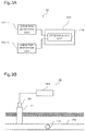
- FIG. 3A illustrates an exemplary diagnostic system including the diagnostic device according to the first example embodiment of the present invention.
- FIG. 3B illustrates the exemplary diagnostic system including the diagnostic device according to the first example embodiment of the present invention.
- FIG. 4 is a block diagram illustrating a configuration of a diagnostic device according to a second example embodiment of the present invention.
- FIG. 5 is a flowchart illustrating an operation of the diagnostic device according to the second example embodiment of the present invention.
- FIG. 6 is a diagram illustrating an exemplary method for deriving a speed of sound by the diagnostic device according to the second example embodiment of the present invention.
- FIG. 7A is a graph representing the relation between the speed of sound in a pipe and the frequency.
- FIG. 7B is a graph representing the relation between the vibration acceleration in the pipe and the frequency.
- FIG. 7C is a graph representing the relation between the vibration acceleration in the pipe and the frequency.
- FIG. 8 is a diagram illustrating another exemplary method for deriving a speed of sound by the diagnostic device according to the second example embodiment of the present invention.
- FIG. 9 is a diagram illustrating a configuration of a diagnostic device according to a third example embodiment of the present invention.
- FIG. 10 is a flowchart illustrating an operation of the diagnostic device according to the third example embodiment of the present invention.
- FIG. 11 is a diagram illustrating a configuration of a diagnostic device according to a fourth example embodiment of the present invention.
- FIG. 12A is a diagram illustrating an exemplary diagnostic method using the diagnostic device according to the fourth example embodiment of the present invention.
- FIG. 12B is a diagram illustrating an exemplary diagnostic method using the diagnostic device according to the fourth example embodiment of the present invention.
- FIG. 12C is a diagram illustrating an exemplary diagnostic method using the diagnostic device according to the fourth example embodiment of the present invention.
- FIG. 13 is a flowchart illustrating an operation of the diagnostic device according to the fourth example embodiment of the present invention.
- FIG. 14 is a diagram illustrating a configuration of a diagnostic device according to a fifth example embodiment of the present invention.
- FIG. 15 illustrates an exemplary diagnostic system including the diagnostic device according to the fifth example embodiment of the present invention.
- FIG. 16 is a flowchart illustrating an operation of the diagnostic device according to the fifth example embodiment of the present invention.
- FIG. 17A is a diagram illustrating an exemplary diagnostic method using the diagnostic device according to the fifth example embodiment of the present invention.
- FIG. 17B is a diagram illustrating an exemplary diagnostic method using the diagnostic device according to the fifth example embodiment of the present invention.
- FIG. 18 is a diagram illustrating an exemplary information processing device for implementing the diagnostic device in each example embodiment of the present invention and the like.
- components constituting each device represent functional unit blocks. Components constituting each device may be implemented by any combination of software and an information processing device 500 as illustrated in, for example, FIG. 18 .
- the information processing device 500 includes, as an example, the following configuration.
- the structure to be determined by a diagnostic device and the like is a pipe through which a fluid flows, such as water supply pipes or gas pipes.
- FIG. 1 is a diagram illustrating a configuration of a diagnostic device according to the first example embodiment of the present invention.
- FIG. 2 is a flowchart illustrating an operation of the diagnostic device according to the first example embodiment of the present invention.
- FIGS. 3A and 3B illustrate an exemplary diagnostic system including the diagnostic device according to the first example embodiment of the present invention.
- a diagnostic device 100 includes a determination unit 110 that determines the condition of a structure such as a pipe based on the speed of sound in the structure.
- the diagnostic device 100 may be implemented as a computer including a CPU and a memory.
- the diagnostic device 100 may also be implemented as a program executed on a server, a PC (Personal Computer), a microcomputer or the like connected to a network.
- the diagnostic device 100 may even be implemented as a logic circuit of hardware.
- the determination unit 110 determines the condition of the structure such as a pipe based on the speed of sound (the speed of propagation of an elastic wave) in the structure. As an example, the determination unit 110 may determine that an abnormality has occurred in the structure such as a pipe when the speed of sound in the pipe or the like is lower than a reference threshold. The determination unit 110 may even determine that an abnormality has occurred in the pipe or the like when the speed of sound in the pipe is higher than a reference threshold. In other words, the threshold used by the determination unit 110 represents the upper limit or lower limit of the speed of sound in the structure or the like when no abnormality has occurred in the pipe or the like (that is, the pipe is normal).
- the determination unit 110 determines that an abnormality has occurred in the structure such as the pipe when the speed of sound in the pipe or the like exceeds the threshold (the speed of sound in the structure such as the pipe is higher or lower than the threshold).
- the determination unit 110 may determine the condition of the structure using either the threshold representing the upper limit or the threshold representing the lower limit described above, or determine the condition of the structure using both the threshold representing the upper limit and the threshold representing the lower limit described above.
- the threshold is determined on the basis of the material and thickness of a pipe to be determined, surrounding conditions of the pipe (the soil surrounding the pipe when it is buried underground) and the like.
- the threshold may be determined in a single step or multiple steps for the upper limit or the lower limit as described above.
- the determination unit 110 may determine the degree of abnormality in the structure such as a pipe, in accordance with any of the multiple-step thresholds when the speed of sound in the pipe or the like is higher or lower than this threshold.
- the determination unit 110 first determines a speed of sound in the structure such as a pipe (step S 101 ).
- the determination unit 110 may obtain an externally calculated speed of sound in the structure such as a pipe, or may obtain externally obtained information regarding the speed of sound in the structure such as a pipe and calculate a speed of sound in the structure such as a pipe on the basis of the information obtained.
- the determination unit 110 determines, for example, whether the speed of sound in the structure such as a pipe that is determined exceeds a reference threshold speed of sound (that is, the speed of sound in the structure such as a pipe is higher or lower than the threshold) (step S 102 ). When the speed of sound in the structure such as a pipe exceeds the threshold (Yes in step S 102 ), the determination unit 110 determines that an abnormality has occurred in the pipe to be determined. In this case, the diagnostic device 100 may notify the external that an abnormality has occurred, for example. The diagnostic device 100 may identify the position at which an abnormality has occurred, using a known method or the like.
- step S 102 When the derived speed of sound in the structure such as a pipe does not exceed the predetermined threshold in step S 102 (No in step S 102 ), the determination unit 110 determines that no abnormality has occurred in the pipe to be determined. In this case, the diagnostic device 100 returns to step S 101 , and obtains a speed of sound.
- the speed of sound propagating through the pipe is determined in a manner that depends on the mechanical propagation property of the structure such as a pipe determined by the factors associated with the pipe or the like including the material and shape of the pipe, and the surrounding environments such as the soil surrounding the pipe.
- the pipe may corrode with time, or deteriorate due to rust, change in thickness, or become cracked or scratched as a fluid flows through the pipe, for example. In this manner, when the pipe changes in thickness and the like, its mechanical propagation property changes. Changes in mechanical propagation property of the pipe results in change of the speed of sound in the pipe.
- the speed of sound may decrease or increase due to changes in the mechanical propagation property of the pipe with time and the like, as described above. Therefore, when the speed of sound in the pipe decreases or increases in excess of a certain threshold, for example, it may be determined that the deterioration of the pipe has worsened.
- the diagnostic device 100 may thus determine the condition of the pipe and the occurrence of an abnormality on the basis of the speed of sound in the pipe.
- the diagnostic device 100 may also determine temporal changes in condition of the pipe on the basis of temporal changes in speed of sound in the pipe.
- the diagnostic system 10 includes the diagnostic device 100 in the present example embodiment and at least one vibration detection unit 101 that detects vibration of a pipe 170 serving as a structure.
- the pipe 170 is buried underground.
- the vibration detection unit 101 is attached to an ancillary equipment 171 such as a fire hydrant or a water stop valve mounted on the pipe 170 .
- the ancillary equipment 171 is not limited to a fire hydrant, a water stop valve or the like as long as vibration propagates to it from the pipe 170 .
- the vibration detection unit 101 detects vibration propagating through the pipe.
- the vibration detection unit 101 may use, for example, a piezoelectric vibration sensor, but not limited to this.
- Information regarding the detected vibration propagating through the pipe is sent to the diagnostic device 100 by a communication means (not illustrated), for example.
- the vibration detection unit 101 When vibration propagating through the pipe 170 is detected by the vibration detection unit 101 , the speed of sound in the pipe may be obtained from the relation between the position of the source of the vibration and the position at which vibration of the pipe 170 is detected by the vibration detection unit 101 , and the time taken for the vibration to propagate.
- the determination unit 110 may determine the condition of the pipe based on the speed of sound obtained from the vibration detected by the vibration detection unit 101 .
- the speed of sound obtained using the vibration detected by the vibration detection unit 101 is the speed of sound of the pipe 170 between the position of the source of the vibration and the position at which vibration is detected by the vibration detection unit 101 .
- the determination unit 110 may determine the condition of the pipe 170 not only at the position where vibration is detected by the vibration detection unit 101 but also at a position away from the position where the vibration is detected by the vibration detection unit 101 , based on the speed of sound which is obtained.
- the vibration detection unit 101 need only to be capable of detecting vibration of the pipe, and may be set at any location that allows detection of vibration of the pipe.
- the vibration detection unit 101 is attached to an ancillary equipment 171 such as a fire hydrant or a water stop valve mounted on the pipe, as illustrated in FIG. 3B .
- the vibration detection unit 101 may be attached to a portion other than the ancillary equipment 171 as long as it may detect vibration of the pipe, and it may be directly attached to the pipe 170 , for example.
- the vibration detection unit 101 may even detect vibration of the pipe at a position away from the pipe 170 or the ancillary equipment 171 , as long as it may detect vibration of the pipe.
- the diagnostic system 10 at least one vibration detection unit 101 is provided, as illustrated in FIG. 3B . Note that, however, two or more vibration detection units 101 may be provided in accordance with the method for determining the speed of sound and the like.
- the diagnostic system 10 may even include a plurality of vibration detection units 101 . In this case, the diagnostic system 10 may be configured to select a vibration detection unit 101 proximate to the position at which the condition of the pipe is desired to be detected among the plurality of vibration detection units 101 , and determine the condition of the pipe using vibration detected by the vibration detection unit 101 which is selected as above.
- the diagnostic device 100 determines the condition of the structure such as a pipe on the basis of the speed of sound.
- the diagnostic device 100 may determine the condition of the pipe or the like, its changes, and the occurrence of an abnormality in the pipe or the like.
- the speed of sound is derived based on vibration detected by the vibration detection unit 101 in the diagnostic system 10 , for example.
- the vibration detection unit 101 need not always be directly attached to the pipe as long as it may detect vibration of the pipe.
- the speed of sound in the structure such as a pipe is easily determined using information regarding the vibration detected by the vibration detection unit 101 .
- the speed of sound obtained from the vibration detected by the vibration detection unit 101 is the speed of sound between the position of the source of the vibration and the position where the vibration of the pipe is detected by the vibration detection unit 101 . Therefore, the diagnostic device 100 according to the present example embodiment may determine the condition of a wide area of the pipe by determining the condition of the pipe based on the speed of sound in the structure such as a pipe.
- the diagnostic device 100 may determine the condition of a wide area of the structure such as a pipe with a simple configuration.
- FIG. 4 is a block diagram illustrating configurations of a diagnostic device and a diagnostic system according to the second example embodiment of the present invention.
- FIG. 5 is a flowchart illustrating an operation of the diagnostic device according to the second example embodiment of the present invention.
- FIG. 6 is a diagram illustrating an exemplary method for determining a speed of sound by the diagnostic device according to the second example embodiment of the present invention.
- FIGS. 7A, 7B, and 7C are graphs each representing the relation between the speed of sound in a pipe and the frequency.
- FIG. 8 is a diagram illustrating another exemplary method for determining a speed of sound by the diagnostic device in the second example embodiment of the present invention.
- a diagnostic device 200 includes a sound speed derivation unit 120 and a determination unit 110 , as illustrated in FIG. 4 .
- the sound speed derivation unit 120 determines a speed of sound in a structure such as a pipe on the basis of vibration of the structure such as a pipe.
- the determination unit 110 determines the condition of the structure such as a pipe based on the speed of sound in the pipe or the like determined by the sound speed derivation unit 120 .
- the diagnostic device 200 according to the present example embodiment is different from the diagnostic device 100 according to the first example embodiment of the present invention in that the former includes the sound speed derivation unit 120 .
- the configuration of the diagnostic device 200 is the similar to that of the diagnostic device 100 according to the first example embodiment of the present invention.
- a diagnostic system 20 that uses the diagnostic device 200 according to the second example embodiment of the present invention may be implemented similarly to the diagnostic system 10 that uses the diagnostic device 100 in the first example embodiment of the present invention.
- the diagnostic system 20 that uses the diagnostic device 200 in the second example embodiment of the present invention includes the diagnostic device 200 and at least one vibration detection unit including vibration detection units 101 - 1 to 101 - n.
- the sound speed derivation unit 120 determines a speed of sound in the structure such as a pipe based on the vibration of the pipe or the like.
- the sound speed derivation unit 120 derives a speed of sound in the structure such as a pipe based on the vibration of the pipe detected by at least one of the vibration detection units 101 that detect vibration of the pipe, for example. A specific procedure for determining the speed of sound by the sound speed derivation unit 120 will be described later.
- the sound speed derivation unit 120 first obtains information regarding vibration of the pipe or the like (step S 201 ).
- the sound speed derivation unit 120 may directly obtain information regarding vibration detected by the vibration detection unit 101 , for example.
- the sound speed derivation unit 120 may obtain information having undergone predetermined processing, such as removal of vibration in frequency bands unnecessary to determine the speed of sound on the vibration detected by the vibration detection unit 101 .
- the sound speed derivation unit 120 determines the speed of sound in the structure such as a pipe based on the information regarding vibration obtained in step S 201 (step S 202 ).
- the determination unit 110 determines whether the speed of sound in the structure such as a pipe which is determined exceeds a threshold that is a reference speed of sound (step S 203 ), for example. When the speed of sound in the structure such as a pipe exceeds the threshold (Yes in step S 203 ), the determination unit 110 determines that an abnormality has occurred in the pipe to be determined.
- the determination unit 110 determines that no abnormality has occurred in the pipe or the like to be determined. In this case, the diagnostic device 200 returns to step S 201 , and obtains the information regarding vibration.
- the sound speed derivation unit 120 derives the speed of sound in the pipe on the basis of vibration detected by one vibration detection unit 101 , as illustrated in FIG. 6 .
- a speed of sound in the pipe is derived based on a distance D between a vibration source position 172 and the vibration detection unit 101 , and the time taken for vibration to reach the vibration detection unit 101 from the vibration source position 172 . More specifically, a speed of sound in the pipe is obtained by dividing the distance D from the vibration source position 172 to the position where the ancillary equipment 171 equipped with the vibration detection unit 101 is mounted on a pipe 170 by the time taken for vibration to reach the vibration detection unit 101 from the vibration source position 172 .
- the distance D may include the height of the ancillary equipment 171 (that is, the distance from the position where the accessory is in contact with the pipe 170 to the position the vibration detection unit 101 is mounted).
- the distance D may be a distance along the propagation path of vibration of the pipe 170 or the like from the vibration source position 172 to the position where the vibration detection unit 101 is disposed.
- Vibration of the pipe 170 used to determine the speed of sound in the pipe by the sound speed derivation unit 120 may be generated by, for example, externally applying an impact to the location of the vibration source position 172 in the pipe 170 or its vicinity. For example, directly vibrating the pipe 170 may apply an impact to the pipe 170 . When the pipe 170 is buried underground, an impact may be applied to the pipe 170 by vibrating the ground surface close to the position where the pipe 170 is buried.
- the sound speed derivation unit 120 may derive the speed of sound in the pipe using vibration generated in the pipe 170 when an impact is applied to the pipe 170 due to any factor, such as when an automobile passes through the ground surface near the position where the pipe 170 is buried.
- the sound speed derivation unit 120 preferably accurately identifies the time at which vibration has occurred to obtain the difference in vibration reaching time.
- the sound speed derivation unit 120 derives the speed of sound in the pipe based on vibration detected by one vibration detection unit 101 , as illustrated in FIG. 6 .
- the sound speed derivation unit 120 derives the speed of sound based on the difference in speed of sound in the pipe for each frequency, as illustrated in FIG. 7A .
- the speed of sound in the pipe varies for each frequency, and generally, the higher the frequency, the higher the speed of sound in the pipe.
- the sound speed derivation unit 120 focuses attention on predetermined frequencies f 1 and f 2 , for example.
- the sound speed derivation unit 120 determines times t 1 and t 2 at which f 1 and f 2 of interest respectively satisfy a predetermined condition (for example, the vibration acceleration reaches a peak). For example, the vibration acceleration for the frequency f 1 reaches a peak at the time t 1 , as illustrated in FIG. 7B .
- the vibration acceleration for the frequency f 2 lower than the frequency f 1 reaches a peak at the time t 2 after the time t 1 , as illustrated in FIG. 7C .
- the sound speed derivation unit 120 derives a speed of sound based on ⁇ t obtained by equation (1) and the above-mentioned distance D. In this way, the sound speed derivation unit 120 may accurately derive a speed of sound even when the time at which vibration has occurred may not be identified.
- the vibration source position 172 When the vibration source position 172 is the same, the speed of sound changes in accordance with changes in ⁇ t.
- the determination unit 110 may determine the condition of the pipe on the basis of ⁇ t.
- Vibration of the pipe 170 used by the sound speed derivation unit 120 to derive the speed of sound in the pipe may be generated as in the foregoing example.
- the sound speed derivation unit 120 derives the speed of sound in the pipe based on vibrations detected by the two vibration detection units 101 - 1 and 101 - 2 , as illustrated in FIG. 8 .
- the sound speed derivation unit 120 derives a speed of sound in the pipe based on the difference between the times at which vibrations have reached the vibration detection units 101 - 1 and 101 - 2 , and the difference between the distances D 1 and D 2 between the vibration source position 172 and the respective positions at which ancillary equipments 171 - 1 and 171 - 2 equipped with the vibration detection units 101 - 1 and 101 - 2 , respectively, are mounted on the pipe 170 .
- the speed of sound is obtained by, for example, dividing the difference between the distances D 1 and D 2 by the difference between the times taken for vibrations to reach the vibration detection units 101 - 1 and 101 - 2 from the vibration source position 172 .
- the distances D 1 and D 2 may include the height of the ancillary equipments 171 - 1 or 171 - 2 , like the above-mentioned distance D.
- the sound speed calculation unit 120 may derive the speed of sound even when no definite vibration source position 172 may be identified.
- the area outside the interval between the vibration detection units 101 - 1 and 101 - 2 is represented in FIG. 8 as a position on the left of the vibration detection unit 101 - 1 of the pipe 170 or that on the right of the vibration detection unit 101 - 2 of the pipe 170 .
- the sound speed calculation unit 120 may derive a speed of sound based the difference between the times taken for vibrations to reach the vibration detection units 101 - 1 and 101 - 2 from the vibration source position 172 , and the distance between the vibration detection units 101 - 1 and 101 - 2 .
- vibration of the pipe 170 used to derive a speed of sound in the pipe by the sound speed derivation unit 120 may be generated as in the foregoing example.
- the sound speed measurement unit 120 may derive the speed of sound using a procedure different from the above-mentioned procedures.
- the sound speed measurement unit 120 may derive the speed of sound in the pipe using an appropriate procedure for the pipe or the like targeted for condition determination, the required accuracy, and the like.
- the diagnostic device 200 in the present example embodiment includes the sound speed derivation unit 120 .
- the sound speed derivation unit 120 derives the speed of sound in the structure such as a pipe based on vibration of the structure such as a pipe.
- a speed of sound in the structure such as a pipe may be easily accurately derived on the basis of vibration of the pipe or the like. Therefore, the diagnostic device 200 in the present example embodiment may determine the condition of the structure easily and accurately.
- the diagnostic system 20 including the diagnostic device 200 in the present example embodiment has the similar advantageous effect as that of the diagnostic device 200 .
- FIG. 9 is a diagram illustrating configurations of a diagnostic device 300 and a diagnostic system 30 according to the third example embodiment of the present invention.
- FIG. 10 is a flowchart illustrating an operation of the diagnostic device 300 in the third example embodiment of the present invention.
- the diagnostic device 300 includes a sound speed derivation unit 120 , a sound speed prediction unit 130 , and a determination unit 110 , as illustrated in FIG. 9 .
- the sound speed derivation unit 120 derives a speed of sound in a structure such as a pipe based on vibration and the like of the structure such as a pipe detected by at least one of vibration detection units 101 - 1 to 101 - n , like the sound speed derivation unit 120 in the second example embodiment of the present invention, for example.
- the sound speed prediction unit 130 predicts a speed of sound in the structure such as a pipe based on at least the speed of sound in the structure such as a pipe derived by the sound speed derivation unit 120 .
- the determination unit 110 determines the condition of the structure such as a pipe based on a predicted value of the speed of sound obtained by the sound speed prediction unit 130 , and the speed of sound in the structure derived by the sound speed derivation unit 120 .
- the diagnostic device 300 in the present example embodiment is different from the diagnostic device 200 in the second example embodiment of the present invention in that the former includes the sound speed prediction unit 130 .
- the configuration is the same as that of the diagnostic device 200 in the second example embodiment of the present invention and the like.
- a diagnostic system 30 that uses the diagnostic device 300 in the third example embodiment of the present invention may be implemented as in the first or second example embodiment of the present invention.
- the diagnostic system 30 that uses the diagnostic device 300 in the third example embodiment of the present invention includes the diagnostic device 300 and vibration detection units 101 - 1 to 101 - n as at least one vibration detection unit.
- the speed of sound in the structure such as a pipe changes, for example, due to aging, or as a fluid flows through the pipe.
- this change in the speed of sound may be considered to result from normal aging and the like.
- the speed of sound in the structure such as a pipe gradually decreases or increases due to aging and the like.
- any abnormality such as cracks or bores, may be considered to have occurred in the pipe or the like.
- the threshold changes in a manner that depends on the mechanical propagation property of the pipe or the like, and the surrounding environments such as the soil surrounding the pipe or the like.
- the predicted value is obtained for the speed of sound on the basis of at least the speed of sound in the structure such as a pipe. The predicted value is thus obtained in consideration of the influence of the above-mentioned factors associating with the speed of sound.
- the diagnostic device 300 in the present example embodiment may accurately determine the condition of the pipe in accordance with its property or environments by predicting the speed of sound in the structure such as a pipe and comparing the predicted value obtained by prediction with the speed of sound derived by, for example, detecting vibration of the pipe to.
- the sound speed prediction unit 130 first predicts the speed of sound in the structure such as a pipe.
- the sound speed prediction unit 130 obtains a predicted value by predicting the speed of sound in the structure such as a pipe at any point in time after a predetermined point in time, based on at least the speed of sound in the structure such as a pipe at the predetermined point in time.
- the predetermined point in time as mentioned above is not limited to one specific point in time, and the sound speed prediction unit 130 may predict based on the speeds of sound in the structure such as a pipe at a plurality of points in time.
- the sound speed prediction unit 130 may take other factors that influence the speed of sound into consideration in obtaining the predicted value.
- the determination unit 110 determines the condition of the structure such as a pipe, on the basis of the value of the speed of sound predicted by the sound speed prediction unit 130 and the speed of sound in the structure derived by the sound speed derivation unit 120 .
- the determination unit 110 may determine the condition of the pipe by, for example, comparing the value of the speed of sound predicted by the sound speed prediction unit 130 with the speed of sound derived by the sound speed derivation unit 120 . In this case, the determination unit 110 may determine that an abnormality has occurred in the pipe when the speed of sound derived by the sound speed derivation unit 120 is different (for example, the speed of sound is lower) than the value of the speed of sound predicted by the sound speed prediction unit 130 beyond a predetermined range.
- the determination unit 110 determines the condition of the pipe preferably on the basis of the speed of sound at a point in time different from that for the speed of sound used to obtain the predicted value of the speed of sound as mentioned above and the predicted value of the speed of sound. Further, the speed of sound in the pipe and its predicted value used in determination by the determination unit 110 are preferably speeds of sound in the same range of the extending pipe. For example, when the speed of sound is derived on the basis of vibration detected by the vibration detection unit 101 , the speed of sound in the pipe used in determination and its predicted value in the determination unit 110 are preferably based on vibration detected by the same vibration detection unit 101 . In this case, the number of vibration detection units 101 is not limited to one.
- the determination unit 110 determines that an abnormality has occurred in the pipe when the speed of sound derived by the sound speed derivation unit 120 is lower than the value of the speed of sound predicted by the sound speed prediction unit 130 beyond a predetermined range.
- the sound speed derivation unit 120 derives a speed of sound in the structure such as a pipe (step S 301 ).
- the sound speed derivation unit 120 derives a speed of sound in the structure such as a pipe on the basis of the vibration detected by the vibration detection unit 101 , for example.
- the sound speed prediction unit 130 predicts a speed of sound in the structure such as a pipe on the basis of at least the speed of sound in the structure such as a pipe derived in step S 301 (step S 302 ).
- the sound speed derivation unit 120 derives a speed of sound in the structure such as a pipe again (step S 303 ).
- the speed of sound derived in this case is the speed of sound in the structure such as a pipe at a point in time after that for the speed of sound derived in step S 301 .
- the determination unit 110 determines whether the speed of sound in the structure such as a pipe derived in step S 303 and the like is lower than the predicted value of the speed of sound obtained in step S 302 (step S 304 ). When the speed of sound in the structure such as a pipe is lower than the predicted value (Yes in step S 304 ), the determination unit 110 determines that an abnormality has occurred in the pipe or the like to be determined.
- the determination unit 110 determines that no abnormality has occurred in the pipe or the like to be determined. In this case, the diagnostic device 300 returns to step S 302 , and predicts the speed of sound in the structure such as a pipe on the basis of the speed of sound derived in step S 303 .
- the diagnostic device 300 includes the sound speed prediction unit 130 .
- the sound speed prediction unit 130 predicts the speed of sound in the structure such as a pipe based on at least the speed of sound in the structure such as a pipe.
- the determination unit 110 determines the condition of the structure such as a pipe based on the predicted value of the speed of sound obtained by the sound speed prediction unit 130 and the speed of sound in the structure. In other words, the determination unit 110 may determine the condition of the structure such as a pipe in consideration of aging.
- the determination unit 110 may more appropriately determine the condition of the pipe or the like in consideration of the environments under which the pipe or the like to be determined is located, variations in performance for each individual vibration detection unit 101 used to derive a speed of sound and the like, than in the case where such determination is done using a threshold. Therefore, the diagnostic device 300 in the present example embodiment may accurately determine the condition of the structure according to the individual conditions of the pipe or the like to be determined.
- the diagnostic system 30 including the diagnostic device 300 in the present example embodiment has similar advantageous effect as that of the diagnostic device 300 .
- FIG. 11 is a diagram illustrating configurations of a diagnostic device and a diagnostic system in the fourth example embodiment of the present invention.
- FIGS. 12A, 12B, and 12C are diagrams illustrating an exemplary diagnostic method using the diagnostic device in the fourth example embodiment of the present invention.
- FIG. 13 is a flowchart illustrating an operation of the diagnostic device in the fourth example embodiment of the present invention.
- a diagnostic device 400 in the fourth example embodiment of the present invention includes a sound speed derivation unit 120 , a sound speed prediction unit 130 , a sound speed storage unit 121 , and a determination unit 110 , as illustrated in FIG. 11 .
- the sound speed derivation unit 120 derives a speed of sound in a structure such as a pipe on the basis of vibration and the like of the structure such as a pipe detected by at least one of vibration detection units 101 - 1 to 101 - n , like the sound speed derivation unit 120 in, for example, the second or third example embodiment of the present invention.
- the sound speed storage unit 121 stores the speed of sound derived by the sound speed derivation unit 120 .
- the sound speed prediction unit 130 predicts the speed of sound in the structure such as a pipe on the basis of the speeds of sound in the structure such as a pipe at a plurality of points in time.
- the sound speed prediction unit 130 may use the speed of sound in the structure such as a pipe stored in the sound speed storage unit 121 as the speed of sound in the structure such as a pipe at each of a plurality of points in time.
- the determination unit 110 determines the condition of the structure such as a pipe on the basis of the predicted value of the speed of sound obtained by the sound speed prediction unit 130 , and the speed of sound in the structure.
- the diagnostic device 400 in the present example embodiment is different from the diagnostic device 300 in the third example embodiment of the present invention in that the sound speed prediction unit 130 included in the former predicts the speed of sound in the structure such as a pipe on the basis of the speeds of sound in the structure such as a pipe at a plurality of points in time. Further, the diagnostic device 400 in the present example embodiment includes a sound speed storage unit 121 that stores the speeds of sound in the structure such as a pipe at a plurality of points in time described earlier. Other than that, the configuration is the same as that of the diagnostic device 300 in the third example embodiment of the present invention, and the like.
- a diagnostic system 40 that uses the diagnostic device 400 in the fourth example embodiment of the present invention may be implemented as in the first to third example embodiments.
- the diagnostic system 40 that uses the diagnostic device 400 in the fourth example embodiment of the present invention includes the diagnostic device 400 and at least one vibration detection unit including vibration detection units 101 - 1 to 101 - n.
- the sound speed prediction unit 130 predicts a speed of sound in the structure such as a pipe on the basis of the speeds of sound at a plurality of points in time. In this way, the sound speed prediction unit 130 may improve the accuracy of the predicted value. This, as a result, may improve the determination accuracy of the condition of the pipe or the like in the determination unit 110 .
- the sound speed prediction unit 130 may use a plurality of speeds of sound during any period for prediction. The sound speed prediction unit 130 may use the plurality of speeds of sound at any interval for prediction.
- the sound speed prediction unit 130 may predict a speed of sound in the structure such as a pipe by obtaining a prediction expression representing a change in the speed of sound in the structure such as a pipe based on the speeds of sound at a plurality of points in time, as illustrated in each of FIGS. 12A, 12B, and 12C .
- the sound speed prediction unit 130 obtains the prediction expression as indicated by a dotted line in FIG. 12A , on the basis of the speeds of sound in the pipe derived at respective times t 1 to t 3 (solid circles at respective times in FIG. 12A ).
- the sound speed prediction unit 130 obtains a prediction expression by approximating the speeds of sound in the pipe at a plurality of points in time using any type of expression such as a polynomial, for example.
- the determination unit 110 uses, as a predicted value, the speed of sound in the pipe obtained from the prediction expression at a time after time t 3 .
- the determination unit 110 determines that no abnormality has occurred in the pipe when the speed of sound in the pipe derived at time t 4 falls within a predetermined range from the value obtained from the prediction expression at the time t 4 . This applies when the speed of sound in the pipe derived at time t 4 is indicated by a dotted circle in FIG. 12A , for example. On the contrary, the determination unit 110 determines that an abnormality has occurred in the pipe when the difference between the speed of sound derived at the time t 4 and the value obtained from the prediction expression at the time t 4 falls outside the predetermined range (for example, the speed of sound at the time t 4 is indicated by a solid circle).
- the sound speed derivation unit 120 included in the diagnostic device 400 derives the speed of sound in the structure such as a pipe (step S 401 ).
- the sound speed derivation unit 120 derives the speed of sound in the structure such as a pipe on the basis of vibration detected by the vibration detection unit 101 , for example.
- the speed of sound in the structure such as a pipe which is derived is stored in the sound speed storage unit 121 .
- the sound speed derivation unit 120 determines whether speeds of sound sufficient in number to predict the speed of sound in the structure such as a pipe have been derived (step S 402 ).
- the sound speed derivation unit 120 determines whether, speeds of sound necessary in number to obtain a prediction expression have been derived for example.
- step S 402 when the sound speed derivation unit 120 determines that insufficient numbers of speeds of sound have been derived to predict the speed of sound in the structure such as a pipe, the sound speed derivation unit 120 returns to step S 401 , in which it repeats derivation of a speed of sound.
- step S 402 when the sound speed derivation unit 120 determines that speeds of sound sufficient in number to predict the speed of sound in the structure such as a pipe have been derived, the diagnostic device 400 advances to the operation in step S 403 .
- step S 403 the sound speed prediction unit 130 predicts the speed of sound in the structure such as a pipe on the basis of the speeds of sound in the structure such as a pipe at a plurality of points in time derived in step S 401 .
- the sound speed prediction unit 130 may predict the speed of sound in the structure such as a pipe by, for example, generating the prediction expression representing a change in speed of sound in the structure such as a pipe.
- the determination unit 110 analyzes the condition of the pipe by determining whether the speed of sound derived at a point in time after that used for prediction in step S 403 , for example, is lower than the predicted value (step S 404 ). When the speed of sound in the structure such as a pipe is lower than the predicted value (Yes in step S 404 ), the determination unit 110 determines that an abnormality has occurred in the pipe to be determined.
- step S 406 determines that no abnormality has occurred in the pipe to be determined. In this case, the diagnostic device 400 returns to step S 401 , and derives the speed of sound.
- the diagnostic device 400 uses the sound speed prediction unit 130 to predict a speed of sound in the structure such as a pipe on the basis of the speeds of sound in the structure such as a pipe at a plurality of points in time. More specifically, the sound speed prediction unit 130 predicts the speed of sound in the structure such as a pipe by obtaining a prediction expression regarding the speed of sound on the basis of the speeds of sound in the structure such as a pipe at a plurality of points in time. The determination unit 110 determines the condition of the structure such as a pipe on the basis of the predicted value of the speed of sound obtained by the sound speed prediction unit 130 , and the speed of sound in the structure.
- the determination unit 110 may determine the condition of the structure such as a pipe in consideration of aging of the structure to be determined. Therefore, the diagnostic device 400 in the present example embodiment may accurately determine the condition of the structure according to the individual conditions of the pipe or the like to be determined, like the diagnostic device 300 in the third example embodiment of the present invention. The diagnostic device 400 in the present example embodiment may more accurately determine the condition of the structure such as a pipe than the diagnostic device 300 in the third example embodiment of the present invention, using a prediction expression regarding the speed of sound in predicting a speed of sound in the structure and determining the state.
- the diagnostic system 40 including the diagnostic device 200 in the present example embodiment has similar advantageous as that of the diagnostic device 400 .
- the determination unit 110 may predict a period during which an abnormality is determined to have occurred in the pipe by obtaining a period during which the speed of sound in the structure such as a pipe predicted from the prediction expression satisfies a predetermined condition to.
- the sound speed prediction unit 130 obtains a prediction expression indicated by a dotted line in FIG. 12B , on the basis of the speeds of sound derived at times t 1 to t 3 .
- the determination unit 110 determines that an abnormality has occurred in the pipe as the speed of sound in the pipe reaches the value indicated by an alternate long and short dashed line illustrated in FIG. 12B , for example, the determination unit 110 predicts that an abnormality will occur in the pipe at time t 5 , at which the speed of sound predicted using a prediction expression falls below the alternate long and short dashed line.
- the determination unit 110 may thus determine the condition of the pipe in more detail.
- a user who uses the diagnostic device in the present modification may maintain the pipe or the like, for example, in consideration of the period during which an abnormality occurs in the pipe or the like.
- the determination unit 110 may determine that an abnormality will occur in the pipe or the like on the basis of the prediction expression itself obtained by the sound speed prediction unit 130 .
- the sound speed prediction unit 130 obtains a prediction expression indicated by a dotted line in FIG. 12C , on the basis of the speeds of sound derived at times t 1 to t 3 .
- the change in the speed of sound is greater after the time t 3 than before the time t 3 .
- the determination unit 110 may determine that an abnormality will occur in the structure such as a pipe, regardless of the determination result of the condition of the pipe or the like based on the predicted value of the speed of sound obtained from the prediction expression and the speed of sound in the pipe or the like. The determination unit 110 may thus determine changes in condition of the pipe in more detail.
- the diagnostic device 400 may change the frequency of derivation of the speeds of sound in the structure such as a pipe used to obtain the predicted value for the speed of sound in the structure such as a pipe by the sound speed prediction unit 130 , or the frequency of determination by the determination unit 110 , on the basis of the determination result obtained by the determination unit 110 .
- the diagnostic device 400 may operate to enhance the frequency of derivation of speeds of sound in steps S 401 and S 402 of FIG. 13 .
- the diagnostic device 400 may further enhance the frequency of determination by the determination unit 110 in step S 404 .
- the predetermined condition mentioned above may be used as, for example, a reference laxer to a certain extent than that for determining by the determination unit 110 that an abnormality has occurred in the pipe or the like.
- the diagnostic device 400 may determine that an abnormality has occurred in the pipe by enhancing the frequency of derivation of speeds of sound and the like at early stage.
- FIG. 14 is a diagram illustrating configurations of a diagnostic device and a diagnostic system in the fifth example embodiment of the present invention.
- FIG. 15 illustrates an exemplary diagnostic system including the diagnostic device in the fifth example embodiment of the present invention.
- FIG. 16 is a flowchart illustrating an operation of the diagnostic device in the fifth example embodiment of the present invention.
- FIGS. 17A and 17B are diagrams illustrating an exemplary diagnostic method using the diagnostic device in the fifth example embodiment of the present invention.
- a diagnostic device 500 includes a sound speed derivation unit 120 , a sound speed prediction unit 130 , and a determination unit 110 , as illustrated in FIG. 14 .
- the sound speed derivation unit 120 derives a speed of sound in a structure such as a pipe on the basis of vibrations and the like of the structure such as a pipe detected by vibration detection units 101 - 1 to 101 - n , like the sound speed derivation unit 120 in the second to fourth example embodiments of the present invention, for example.
- the sound speed prediction unit 130 predicts a speed of sound in the structure such as a pipe based on the speed of sound in the structure such as a pipe and, for example, a physical quantity associated with the pipe or the like measured by a physical quantity measuring unit 102 or a factor that may influence the speed of sound in the pipe or the like.
- examples of the physical quantity used in this case include the pressure, flow rate, and temperature of a fluid flowing through the pipe.
- the factor that may influence the speed of sound in the pipe or the like include the type of fluid flowing through the pipe.
- the determination unit 110 determines the condition of the structure such as a pipe on the basis of the predicted value of the speed of sound obtained by the sound speed prediction unit 130 , and the speed of sound in the structure.
- the diagnostic device 500 in the present example embodiment is different from the diagnostic device 300 in the third example embodiment of the present invention in that, the sound speed prediction unit 130 included in the former predicts the speed of sound in the structure such as a pipe further on the basis of a physical quantity associated with the pipe or the like.
- the configuration is the same as that of the diagnostic device 300 in the third example embodiment of the present invention, and the like.
- a diagnostic system 50 that uses the diagnostic device 500 in the fifth example embodiment may be implemented as illustrated in FIG. 15 .
- the diagnostic system 50 includes the diagnostic device 500 , at least one vibration detection unit including vibration detection units 101 - 1 to 101 - n that detect vibration of a pipe 170 as a structure, and a physical quantity measuring unit 102 that measures a physical quantity associated with the pipe 170 .
- the physical quantity measuring unit 102 more specifically, uses a measuring instrument according to the physical quantity used in predicting the speed of sound. For example, a thermometer, a pressure gauge that measures the pressure in the pipe, or a flowmeter that measures the flow rate of a fluid flowing through the pipe is used.
- the physical quantity measuring unit 102 is attached to the pipe, or an ancillary equipment 171 such as a fire hydrant or a water stop valve mounted on the pipe, like the vibration detection unit 101 .
- the physical quantity measuring unit 102 may be attached to an area other than the above-mentioned examples.
- the sound speed prediction unit 130 predicts the speed of sound in the structure such as a pipe based on the speed of sound in the structure such as a pipe, and the physical quantity associated with the pipe or the like.
- the structure such as a pipe may vary in degree of worsening of deterioration according to the surrounding conditions.
- the pressure, flow rate, temperature, and the like of a fluid flowing through it act as factors that influence deterioration of the pipe in this manner.
- the speed of sound in the structure such as a pipe is influenced by its material, shape, and installation environment, and factors other than its deterioration condition.
- the speed of sound in the pipe is further influenced by factors such as the pressure, flow rate, temperature, and the like of a fluid flowing through the pipe.
- the prediction accuracy of the speed of sound in the pipe or the like may be improved by taking these factors that influence the speed of sound into consideration.
- the sound speed prediction unit 130 predicts a speed of sound in the structure such as a pipe from the speed of sound at a particular point in time, and the physical quantity associated with the pipe or the like at that point in time.
- the sound speed prediction unit 130 predicts the speed of sound in the pipe at time t 2 from the speed of sound in the pipe at time t 1 , and the physical quantity associated with the pipe or the like at the time t 1 .
- the speed of sound to be predicted may be predicted as the range of speed of sound, as indicated by a vertical bar at the time t 2 in FIG. 17A . Referring to FIG.
- the sound speed prediction unit 130 similarly predicts a speed of sound in the pipe at time t 3 from the speed of sound in the pipe at the time t 2 , and the physical quantity associated with the pipe or the like at the time t 2 .
- the sound speed prediction unit 130 further predicts the speed of sound in the pipe at time t 4 from the speed of sound in the pipe at the time t 3 , and the physical quantity associated with the pipe or the like at the time t 4 .
- the determination unit 110 may determine that no abnormality has occurred in the pipe or the like when the speed of sound in the structure such as a pipe falls within the range of speed of sound predicted by the sound speed prediction unit 130 .
- the determination unit 110 may determine that an abnormality has occurred in the pipe or the like when the speed of sound in the structure such as a pipe falls outside the range of speed of sound predicted by the sound speed prediction unit 130 .
- the sound speed derivation unit 120 derives a speed of sound in the structure such as a pipe (step S 501 ).
- the sound speed derivation unit 120 derives a speed of sound in the structure such as a pipe on the basis of, for example, vibration detected by the vibration detection unit 101 .
- the sound speed prediction unit 130 measures a predetermined physical quantity associated with the pipe (step S 502 ).
- the sound speed prediction unit 130 measures a physical quantity using the physical quantity measuring unit 102 .
- the sound speed prediction unit 130 predicts the speed of sound in the structure such as a pipe on the basis of the speed of sound in the structure such as a pipe derived in step S 501 , and the physical quantity associated with the pipe measured in step S 502 (step S 503 ).
- the sound speed derivation unit 120 derives the speed of sound in the structure such as a pipe again (step S 504 ).
- the speed of sound derived in this case is the speed of sound in the structure such as a pipe at the point in time at which a predicted value has been calculated in step S 503 .
- the determination unit 110 determines whether the speed of sound in the structure such as a pipe or the like derived in step S 504 falls outside the range of predicted value of the speed of sound obtained in step S 503 (step S 505 ). When the speed of sound in the structure such as a pipe falls outside the range of predicted value (Yes in step S 505 ), the determination unit 110 determines that an abnormality has occurred in the pipe or the like to be determined.
- step S 505 When the derived speed of sound in the structure such as a pipe falls within the range of predicted value in step S 505 (No in step S 505 ), the determination unit 110 determines that no abnormality has occurred in the pipe to be determined. In this case, the diagnostic device 300 returns to step S 502 , and measures the physical quantity associated with the pipe again. In step S 503 , the sound speed prediction unit 130 predicts a speed of sound in the structure such as a pipe based on the previous speed of sound derived in step S 504 , and the physical quantity associated with the pipe measured again in step S 502 .
- the diagnostic device 500 uses the sound speed prediction unit 130 to predict the speed of sound in the structure such as a pipe based on the speed of sound in the structure such as a pipe, and the physical quantity associated with the structure such as a pipe.
- the speed of sound in the structure such as a pipe may change in a manner that depends on the physical quantity associated with the pipe or the like.
- the sound speed prediction unit 130 may more accurately predict a speed of sound in the structure such as a pipe according to the individual conditions of the pipe or the like.
- the determination unit 110 determines the condition of the structure such as a pipe, based on the predicted value of the speed of sound obtained by the sound speed prediction unit 130 and the speed of sound in the structure.
- the diagnostic device 500 in the present example embodiment may more accurately determine the condition of the structure than the diagnostic device 300 in the third example embodiment of the present invention.
- the configuration of the diagnostic device 500 in the fifth example embodiment may be used in combination of the diagnostic device 400 in the fourth example embodiment of the present invention where necessary.
- the determination unit 110 may determine that an abnormality will occur in the pipe by determining whether the range of the speed of sound in the pipe predicted by the sound speed prediction unit 130 exceeds a predetermined threshold.
- the sound speed prediction unit 130 predicts a predicted value for the speed of sound at the next time point as a range of speed of sound, on the basis of the speeds of sound derived at respective times t 1 to t 3 , and the physical quantity associated with the pipe at each point in time.
- the determination unit 110 may determine that an abnormality will occur in the pipe when the predicted range of speed of sound is lower or higher than the predetermined threshold.
- the determination unit 110 determines that an abnormality has occurred in the pipe in the case where, for example, the speed of sound in the pipe reaches the value indicated by an alternate long and short dashed line illustrated in FIG. 17B , the determination unit 110 predicts that an abnormality will occur in the pipe at time t 4 at which the predicted range of speed of sound intersects the alternate long and short dashed line.
- the determination unit 110 may thus determine the condition of the pipe in more detail.
- a user who uses the diagnostic device in the present modification may maintain the pipe or the like in consideration of, for example, the period during which an abnormality occurs in the pipe or the like.
- the diagnostic device 500 may be configured to control controllable ones of physical quantities used to predict a speed of sound in the structure such as a pipe by the sound speed prediction unit 130 when the determination unit 110 determines that an abnormality has occurred in the pipe or the like. For example, when the pressure in the pipe is used to predict the speed of sound in the structure such as a pipe by the sound speed prediction unit 130 , the diagnostic device 500 may perform control to lower the pressure in the pipe when the determination unit 110 determines that an abnormality has occurred in the pipe or the like.
- the diagnostic device 500 may perform control to reduce the flow rate in the pipe when the determination unit 110 determines that an abnormality has occurred in the pipe or the like.
- the diagnostic device 500 may control the physical quantity not only by directly controlling it but also by controlling it using other devices.
- the diagnostic device 500 may not only simply determine the condition of the pipe or the like but also suppress worsening of an abnormality in the pipe or the like when the abnormality has occurred in the pipe or the like.
- each example embodiment of the present invention has been described above, including a description of the diagnostic device and the like in this example embodiment assuming, as an example, that the structure to be determined is a pipe.
- the structure to be determined by the diagnostic device and the like in each example embodiment of the present invention is not limited to a pipe.
- the diagnostic device and the like in each example embodiment of the present invention may be applicable to, for example, a bridge or a building as a structure to be determined.
Abstract
Description
-
- CPU (Central Processing Unit) 501
- ROM (Read Only Memory) 502
- RAM (Ramdom Access Memory) 503
- a
program 504 loaded into theRAM 503 - a
storage device 505 that stores theprogram 504 - a
drive device 507 that performs read and write on astorage medium 506 - a
communication interface 508 connected to acommunication network 509 - an I/
O interface 510 that inputs and outputs data - a
bus 511 that connects respective components together
Various modifications are available to implement each device. Each device may be implemented as, for example, a dedicated device. Each device may even be implemented in a combination of a plurality of devices.
Δt=t2−t1 (1)
The sound
- 10, 20, 30, 40, 50 diagnostic system
- 100, 200, 300, 400, 500 diagnostic device
- 101 vibration detection unit
- 102 physical quantity measuring unit
- 110 determination unit
- 120 sound speed derivation unit
- 121 sound speed storage unit
- 130 sound speed prediction unit
- 170 pipe
- 171 ancillary equipment
- 172 vibration source position
- 500 information processing device
- 501 CPU
- 502 ROM
- 503 RAM
- 504 program
- 505 storage device
- 506 storage medium
- 507 drive device
- 508 communication interface
- 509 communication network
- 510 I/O interface
- 511 bus
Claims (10)
Applications Claiming Priority (3)
| Application Number | Priority Date | Filing Date | Title |
|---|---|---|---|
| JP2014154522 | 2014-07-30 | ||
| JP2014-154522 | 2014-07-30 | ||
| PCT/JP2015/003818 WO2016017168A1 (en) | 2014-07-30 | 2015-07-29 | Diagnostic device, diagnostic system, diagnostic method, and computer-readable recording medium |
Publications (2)
| Publication Number | Publication Date |
|---|---|
| US20170205376A1 US20170205376A1 (en) | 2017-07-20 |
| US10823705B2 true US10823705B2 (en) | 2020-11-03 |
Family
ID=55217079
Family Applications (1)
| Application Number | Title | Priority Date | Filing Date |
|---|---|---|---|
| US15/329,124 Active US10823705B2 (en) | 2014-07-30 | 2015-07-29 | Diagnostic device, diagnostic system, diagnostic method, and computer-readable recording medium |
Country Status (4)
| Country | Link |
|---|---|
| US (1) | US10823705B2 (en) |
| JP (1) | JPWO2016017168A1 (en) |
| GB (1) | GB2544668B (en) |
| WO (1) | WO2016017168A1 (en) |
Families Citing this family (3)
| Publication number | Priority date | Publication date | Assignee | Title |
|---|---|---|---|---|
| US10823705B2 (en) | 2014-07-30 | 2020-11-03 | Nec Corporation | Diagnostic device, diagnostic system, diagnostic method, and computer-readable recording medium |
| US11614205B2 (en) * | 2016-02-26 | 2023-03-28 | Nec Corporation | Piping diagnostic device, piping diagnostic method, discriminant-problem optimizing device, discriminant-problem optimizing method, criteria distribution generating device, criteria distribution generating method, and storage medium |
| CN108845030A (en) * | 2018-05-03 | 2018-11-20 | 张家港申乾工程技术服务有限公司 | A method of detecting tube circumference medium state in large diameter pipeline |
Citations (13)
| Publication number | Priority date | Publication date | Assignee | Title |
|---|---|---|---|---|
| US5608845A (en) * | 1989-03-17 | 1997-03-04 | Hitachi, Ltd. | Method for diagnosing a remaining lifetime, apparatus for diagnosing a remaining lifetime, method for displaying remaining lifetime data, display apparatus and expert system |
| JPH11108720A (en) | 1997-09-30 | 1999-04-23 | Yazaki Corp | Gas meter |
| JP2002328119A (en) | 2001-05-01 | 2002-11-15 | Hideo Nishino | Method of estimating tube parameter, method of evaluating condition of tube material, method of inspecting tube, and device for estimating tube parameter used therefor |
| JP2003130854A (en) | 2001-10-22 | 2003-05-08 | Chubu Electric Power Co Inc | Pipe arrangement examining method and device |
| JP2004061361A (en) | 2002-07-30 | 2004-02-26 | Toshiba Corp | Piping breakage investigating apparatus |
| US20060266127A1 (en) * | 2005-05-27 | 2006-11-30 | Gysling Daniel L | Apparatus and method for fiscal measuring of an aerated fluid |
| US20060288756A1 (en) * | 2003-02-21 | 2006-12-28 | De Meurechy Guido D K | Method and apparatus for scanning corrosion and surface defects |
| JP2007003537A (en) | 2006-08-23 | 2007-01-11 | Hitachi Ltd | Piping inspection method and device |
| JP2008064540A (en) | 2006-09-06 | 2008-03-21 | Hitachi Ltd | Piping inspection method using guide wave and piping inspection device |
| JP2013044523A (en) | 2011-08-20 | 2013-03-04 | Dia Consultant:Kk | Diagnostic method for concrete pipe |
| US20140025319A1 (en) * | 2012-07-17 | 2014-01-23 | Chevron Usa Inc. | Structure monitoring |
| WO2014050618A1 (en) | 2012-09-28 | 2014-04-03 | 日本電気株式会社 | Defect analysis device, defect analysis method, and program |
| US20170205376A1 (en) | 2014-07-30 | 2017-07-20 | Nec Corporation | Diagnostic device, diagnostic system, diagnostic method, and computer-readable recording medium |
Family Cites Families (1)
| Publication number | Priority date | Publication date | Assignee | Title |
|---|---|---|---|---|
| JP4162967B2 (en) * | 2001-10-12 | 2008-10-08 | 積水化学工業株式会社 | Inspection method for reinforced concrete pipes |
-
2015
- 2015-07-29 US US15/329,124 patent/US10823705B2/en active Active
- 2015-07-29 WO PCT/JP2015/003818 patent/WO2016017168A1/en active Application Filing
- 2015-07-29 JP JP2016537758A patent/JPWO2016017168A1/en active Pending
- 2015-07-29 GB GB1700948.1A patent/GB2544668B/en active Active
Patent Citations (14)
| Publication number | Priority date | Publication date | Assignee | Title |
|---|---|---|---|---|
| US5608845A (en) * | 1989-03-17 | 1997-03-04 | Hitachi, Ltd. | Method for diagnosing a remaining lifetime, apparatus for diagnosing a remaining lifetime, method for displaying remaining lifetime data, display apparatus and expert system |
| JPH11108720A (en) | 1997-09-30 | 1999-04-23 | Yazaki Corp | Gas meter |
| JP2002328119A (en) | 2001-05-01 | 2002-11-15 | Hideo Nishino | Method of estimating tube parameter, method of evaluating condition of tube material, method of inspecting tube, and device for estimating tube parameter used therefor |
| JP2003130854A (en) | 2001-10-22 | 2003-05-08 | Chubu Electric Power Co Inc | Pipe arrangement examining method and device |
| JP2004061361A (en) | 2002-07-30 | 2004-02-26 | Toshiba Corp | Piping breakage investigating apparatus |
| US20060288756A1 (en) * | 2003-02-21 | 2006-12-28 | De Meurechy Guido D K | Method and apparatus for scanning corrosion and surface defects |
| US20060266127A1 (en) * | 2005-05-27 | 2006-11-30 | Gysling Daniel L | Apparatus and method for fiscal measuring of an aerated fluid |
| JP2007003537A (en) | 2006-08-23 | 2007-01-11 | Hitachi Ltd | Piping inspection method and device |
| JP2008064540A (en) | 2006-09-06 | 2008-03-21 | Hitachi Ltd | Piping inspection method using guide wave and piping inspection device |
| JP2013044523A (en) | 2011-08-20 | 2013-03-04 | Dia Consultant:Kk | Diagnostic method for concrete pipe |
| US20140025319A1 (en) * | 2012-07-17 | 2014-01-23 | Chevron Usa Inc. | Structure monitoring |
| WO2014050618A1 (en) | 2012-09-28 | 2014-04-03 | 日本電気株式会社 | Defect analysis device, defect analysis method, and program |
| JPWO2014050618A1 (en) * | 2012-09-28 | 2016-08-22 | 日本電気株式会社 | Defect analysis apparatus, defect analysis method and program |
| US20170205376A1 (en) | 2014-07-30 | 2017-07-20 | Nec Corporation | Diagnostic device, diagnostic system, diagnostic method, and computer-readable recording medium |
Non-Patent Citations (2)
| Title |
|---|
| International Search Report, Corresponding to PCT/JP2015/003818, dated Oct. 20, 2015, 1 page. |
| United Kingdom Examination Report issued in GB Application No. 1700948.1, dated Aug. 26, 2020, 2 pages. |
Also Published As
| Publication number | Publication date |
|---|---|
| GB2544668A (en) | 2017-05-24 |
| GB2544668B (en) | 2021-02-10 |
| GB201700948D0 (en) | 2017-03-08 |
| GB2544668A8 (en) | 2017-06-21 |
| JPWO2016017168A1 (en) | 2017-04-27 |
| WO2016017168A1 (en) | 2016-02-04 |
| US20170205376A1 (en) | 2017-07-20 |
Similar Documents
| Publication | Publication Date | Title |
|---|---|---|
| US9310237B2 (en) | Ultrasonic flow metering using compensated computed temperature | |
| US10823705B2 (en) | Diagnostic device, diagnostic system, diagnostic method, and computer-readable recording medium | |
| US20180292292A1 (en) | Pipe condition detection device, pipe condition detection method, computer-readable recording medium, and pipe condition detection system | |
| US20140198822A1 (en) | Apparatus and method for determining temperature | |
| JP2011185921A (en) | System and method for measuring damage length | |
| EP3594653B1 (en) | Diagnosis cost output device, diagnosis cost output method, and diagnosis cost output | |
| US10697861B2 (en) | Structure abnormality detection device, structure abnormality detection method, storage medium, and structure abnormality detection system | |
| JP6582855B2 (en) | Flow rate measuring device and flow rate measuring method | |
| US20180348080A1 (en) | Device, method, and recording medium | |
| US20170343514A1 (en) | Piping inspection system, piping inspection device, piping inspection method, and recording medium | |
| KR102038689B1 (en) | Apparatus for sensing leakage of pipe using distance-difference frequency analysis and method thereof | |
| JP2019109194A (en) | Flow rate measuring device | |
| JPWO2016152143A1 (en) | Defect analysis apparatus, defect analysis system, defect analysis method, and computer-readable recording medium | |
| JP7078060B2 (en) | Analytical instrument and diagnostic system | |
| US11249009B2 (en) | Diagnostic device, diagnostic system, diagnostic method, and computer-readable recording medium | |
| JP2006300854A (en) | Piping plate thickness measuring device | |
| JP5841027B2 (en) | Inspection apparatus and inspection method | |
| JP7147305B2 (en) | PIPING DIAGNOSTIC METHOD, PIPING DIAGNOSTIC DEVICE, AND PIPING DIAGNOSTIC SYSTEM | |
| JP2013181812A (en) | Clamp-on type ultrasonic flowmeter | |
| US20180136173A1 (en) | Condition assessment device, condition assessment method, program recording medium | |
| JP2016057241A (en) | Analyzer, analysis system, analysis method and program | |
| WO2015146109A1 (en) | Flaw analysis device, flaw analysis method, and storage medium | |
| KR101993058B1 (en) | Detecting apparatus and method for oil leak | |
| JP2016109560A (en) | Flow rate measurement device and flow rate measurement method | |
| JPWO2019021991A1 (en) | Analysis device, analysis method, and storage medium |
Legal Events
| Date | Code | Title | Description |
|---|---|---|---|
| AS | Assignment |
Owner name: NEC CORPORATION, JAPAN Free format text: ASSIGNMENT OF ASSIGNORS INTEREST;ASSIGNORS:TOMINAGA, SHIN;TAKAHASHI, MASATAKE;MATAGA, JUNICHIRO;AND OTHERS;REEL/FRAME:041081/0946 Effective date: 20170106 |
|
| STPP | Information on status: patent application and granting procedure in general |
Free format text: FINAL REJECTION MAILED |
|
| STPP | Information on status: patent application and granting procedure in general |
Free format text: RESPONSE AFTER FINAL ACTION FORWARDED TO EXAMINER |
|
| STPP | Information on status: patent application and granting procedure in general |
Free format text: DOCKETED NEW CASE - READY FOR EXAMINATION |
|
| STPP | Information on status: patent application and granting procedure in general |
Free format text: NON FINAL ACTION MAILED |
|
| STPP | Information on status: patent application and granting procedure in general |
Free format text: RESPONSE TO NON-FINAL OFFICE ACTION ENTERED AND FORWARDED TO EXAMINER |
|
| STPP | Information on status: patent application and granting procedure in general |
Free format text: NOTICE OF ALLOWANCE MAILED -- APPLICATION RECEIVED IN OFFICE OF PUBLICATIONS |
|
| STCF | Information on status: patent grant |
Free format text: PATENTED CASE |